Embed Size (px)
Citation preview
Dwight Bradshaw • General [email protected]: 970.232.9344 Cell: 970.412.8264VoyagerInstruments.com
Pioneer Engineering is a leading engineering services company that
provides their clients with personalized
services that meet their clients’ individual needs,
worldwide. They are experts in the fields of
reliability and mechanical engineering, identifying
opportunities to help improve equipment
efficiency and life cycle.
CASE STUDY:Rotor Bar Fault in AC InductionSUMMARYPioneer was working with a client in the coal-fired power plant industry to identify a malfunction in one of their AC induction motors. This AC induction motor was fitted with journal bearings and was the driver for a Primary Air Fan. The client had proximity probes and case mounted accelerometers installed on the AC induction motor. At first, the proximity probes seemed to indicate a rotor bar fault, while the accelerometers gave the impression of some kind of impact event happening. After analyzing the data and correctly identifying the malfunction as a rotor bar fault, Pioneer wanted to help their client get better data on their assets and capture data on their uncovered equipment to help them run their plant with more efficiency. Pioneer recommended that their client test the Insight Force Detection System (FDS) on the AC induction motor with the known rotor bar fault in conjunction with the proximity probes and accelerometers to see that they could have better data and less installation costs if they had used the Insight FDS. The customer ordered 40 more Insight FDS to install throughout their plant.
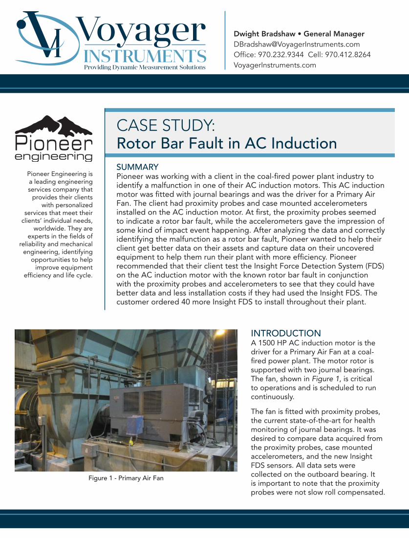
INTRODUCTIONA 1500 HP AC induction motor is the driver for a Primary Air Fan at a coal-fired power plant. The motor rotor is supported with two journal bearings. The fan, shown in Figure 1, is critical to operations and is scheduled to run continuously.
The fan is fitted with proximity probes, the current state-of-the-art for health monitoring of journal bearings. It was desired to compare data acquired from the proximity probes, case mounted accelerometers, and the new Insight FDS sensors. All data sets were collected on the outboard bearing. It is important to note that the proximity probes were not slow roll compensated.
Figure 1 - Primary Air Fan
CASE STUDY:Rotor Bar Fault in AC Induction
VoyagerInsturments.com
COMPARISON DATAThe data captured was from the proximity probes, case mounted accelerometers, and Insight FDS with the same settings and time comparison.
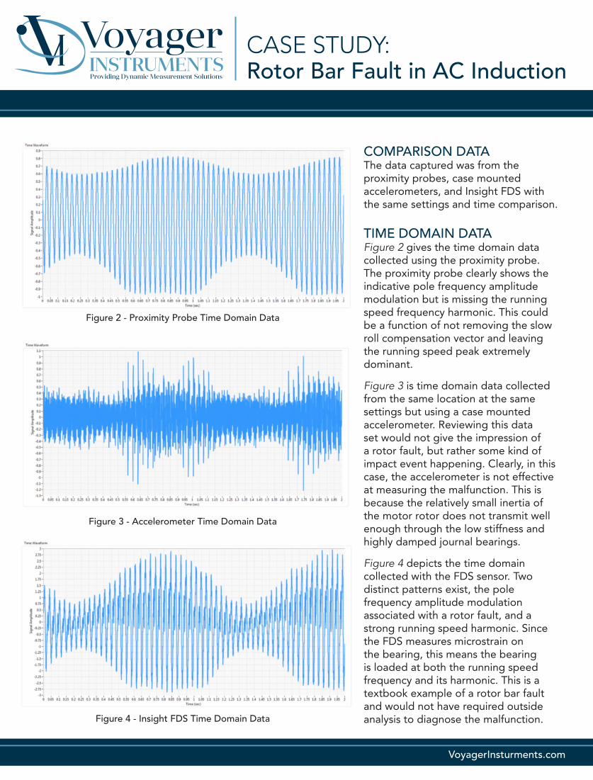
TIME DOMAIN DATAFigure 2 gives the time domain data collected using the proximity probe. The proximity probe clearly shows the indicative pole frequency amplitude modulation but is missing the running speed frequency harmonic. This could be a function of not removing the slow roll compensation vector and leaving the running speed peak extremely dominant.
Figure 3 is time domain data collected from the same location at the same settings but using a case mounted accelerometer. Reviewing this data set would not give the impression of a rotor fault, but rather some kind of impact event happening. Clearly, in this case, the accelerometer is not effective at measuring the malfunction. This is because the relatively small inertia of the motor rotor does not transmit well enough through the low stiffness and highly damped journal bearings.
Figure 4 depicts the time domain collected with the FDS sensor. Two distinct patterns exist, the pole frequency amplitude modulation associated with a rotor fault, and a strong running speed harmonic. Since the FDS measures microstrain on the bearing, this means the bearing is loaded at both the running speed frequency and its harmonic. This is a textbook example of a rotor bar fault and would not have required outside analysis to diagnose the malfunction.
Figure 2 - Proximity Probe Time Domain Data
Figure 3 - Accelerometer Time Domain Data
Figure 4 - Insight FDS Time Domain Data
CASE STUDY:Rotor Bar Fault in AC Induction
VoyagerInsturments.com
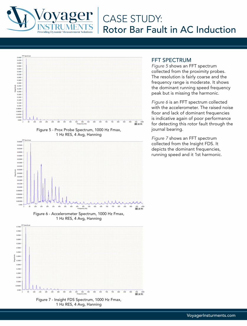
FFT SPECTRUMFigure 5 shows an FFT spectrum collected from the proximity probes. The resolution is fairly coarse and the frequency range is moderate. It shows the dominant running speed frequency peak but is missing the harmonic.
Figure 6 is an FFT spectrum collected with the accelerometer. The raised noise floor and lack of dominant frequencies is indicative again of poor performance for detecting this rotor fault through the journal bearing.
Figure 7 shows an FFT spectrum collected from the Insight FDS. It depicts the dominant frequencies, running speed and it 1st harmonic.
Figure 5 - Prox Probe Spectrum, 1000 Hz Fmax, 1 Hz RES, 4 Avg, Hanning
Figure 6 - Accelerometer Spectrum, 1000 Hz Fmax, 1 Hz RES, 4 Avg, Hanning
Figure 7 - Insight FDS Spectrum, 1000 Hz Fmax, 1 Hz RES, 4 Avg, Hanning
CASE STUDY:Rotor Bar Fault in AC Induction
VoyagerInsturments.com
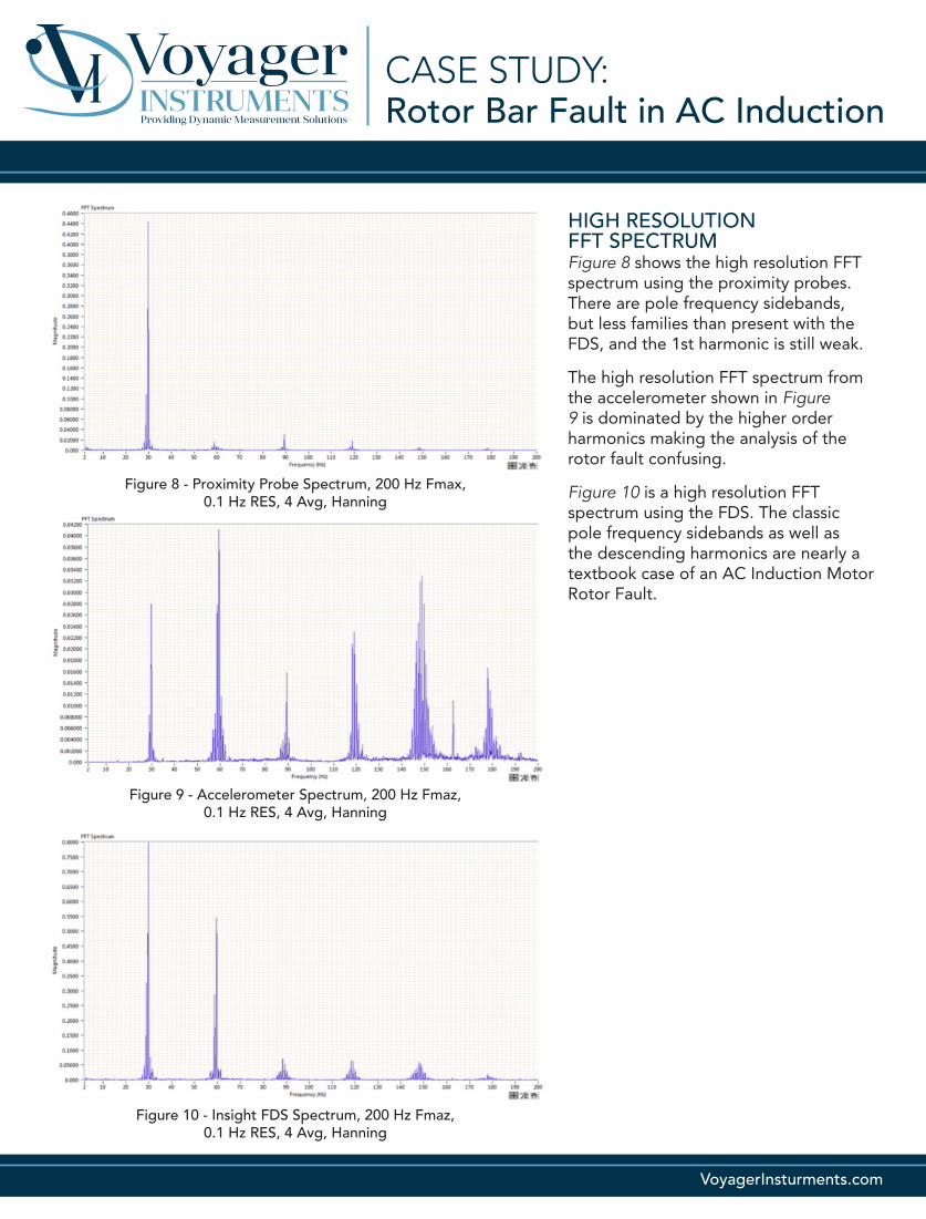
HIGH RESOLUTION FFT SPECTRUMFigure 8 shows the high resolution FFT spectrum using the proximity probes. There are pole frequency sidebands, but less families than present with the FDS, and the 1st harmonic is still weak.
The high resolution FFT spectrum from the accelerometer shown in Figure 9 is dominated by the higher order harmonics making the analysis of the rotor fault confusing.
Figure 10 is a high resolution FFT spectrum using the FDS. The classic pole frequency sidebands as well as the descending harmonics are nearly a textbook case of an AC Induction Motor Rotor Fault.
Figure 8 - Proximity Probe Spectrum, 200 Hz Fmax, 0.1 Hz RES, 4 Avg, Hanning
Figure 9 - Accelerometer Spectrum, 200 Hz Fmaz, 0.1 Hz RES, 4 Avg, Hanning
Figure 10 - Insight FDS Spectrum, 200 Hz Fmaz, 0.1 Hz RES, 4 Avg, Hanning
Dwight Bradshaw • General [email protected]: 970.232.9344 Cell: 970.412.8264VoyagerInstruments.com
Pioneer Engineering is a leading engineering services company that
provides their clients with personalized
services that meet their clients’ individual needs,
worldwide. They are experts in the fields of
reliability and mechanical engineering, identifying
opportunities to help improve equipment
efficiency and life cycle.
CASE STUDY:
CONCLUSIONIn this case, the case mounted accelerometer proved nearly ineffective at presenting the known rotor fault in the motor.
The proximity probe did show evidence of the rotor fault, but not as definitively as the Insight FDS sensor.
The Insight FDS sensor clearly detects the rotor fault using both the time and frequency domains.
Given that the accelerometer data is nearly useless, and the proximity probe data requires an extremely invasive installation, as well as a vector compensation in order to be accurate, the Insight FDS is a first choice since its installation is non-invasive and materials are less expensive than proximity probes.
As a result, the customer replaced the motor at the next shutdown. Additionally, they placed an order for 40 Insight FDS to be installed in the plant on ID fans, FD fans, PA fans and Boiler Feed Pump motors.
Rotor Bar Fault in AC Induction