Embed Size (px)
Citation preview
ROTATING AERODYNAMIC-EXCITERS for in-flight flutter testing
Item Type text; Proceedings
Authors PENNACHIONI, M.
Publisher International Foundation for Telemetering
Journal International Telemetering Conference Proceedings
Rights Copyright © International Foundation for Telemetering
Download date 19/08/2018 08:59:07
Link to Item http://hdl.handle.net/10150/615759
ROTATING AERODYNAMIC- EXCITERSfor in-flight flutter testing
M. PENNACHIONI
IN-FLIGHT TESTS CENTREIstres Aircraft Testing Base
Methods Department
1 - Structural excitation as observed in in-flight flutter testing.
Telemetering, as used in in-flight testing, has several advantages including that ofallowing what is known as real-time utilization; and thereby, in certain specific cases, thecontinuation of the flight programme in terms of the results obtained therein.
This feature is especially attractive during the opening of the aircraft’s flutter envelope.It then becomes a matter of experimentally determining the aircraft’s aeroelastic stabilitythroughout its flight envelope, and specifically at high speeds. In this connection, it’scommon knowledge that in excess of a certain so-called critical speed, two or morevibratory modes of the structure can become coupled via the aerodynamic forces theyrespectively generate; and can lead to diverging oscillation liable to cause vibration failure.It’s easy to see that such a critical speed must be well within the permitted aircraftoperation envelope and that approaching it during in-flight testing should only beconsidered with a certain amount of prudence and subject to strict monitoring of thestructure’s behaviour.
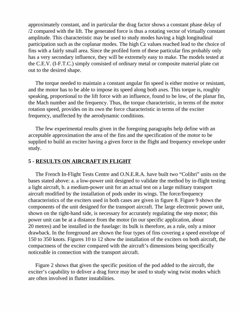
The most widely used monitoring system is to measure the transfer function relating analternating force applied to the aircraft structure in flight to the displacements it causes atdifferent points of that structure (figure 1).
Progress in the flight envelope is made in speed steps, any variations in this transferfunction being monitored between steps, and usually being reflected in terms of vibrationfrequencies and damping.
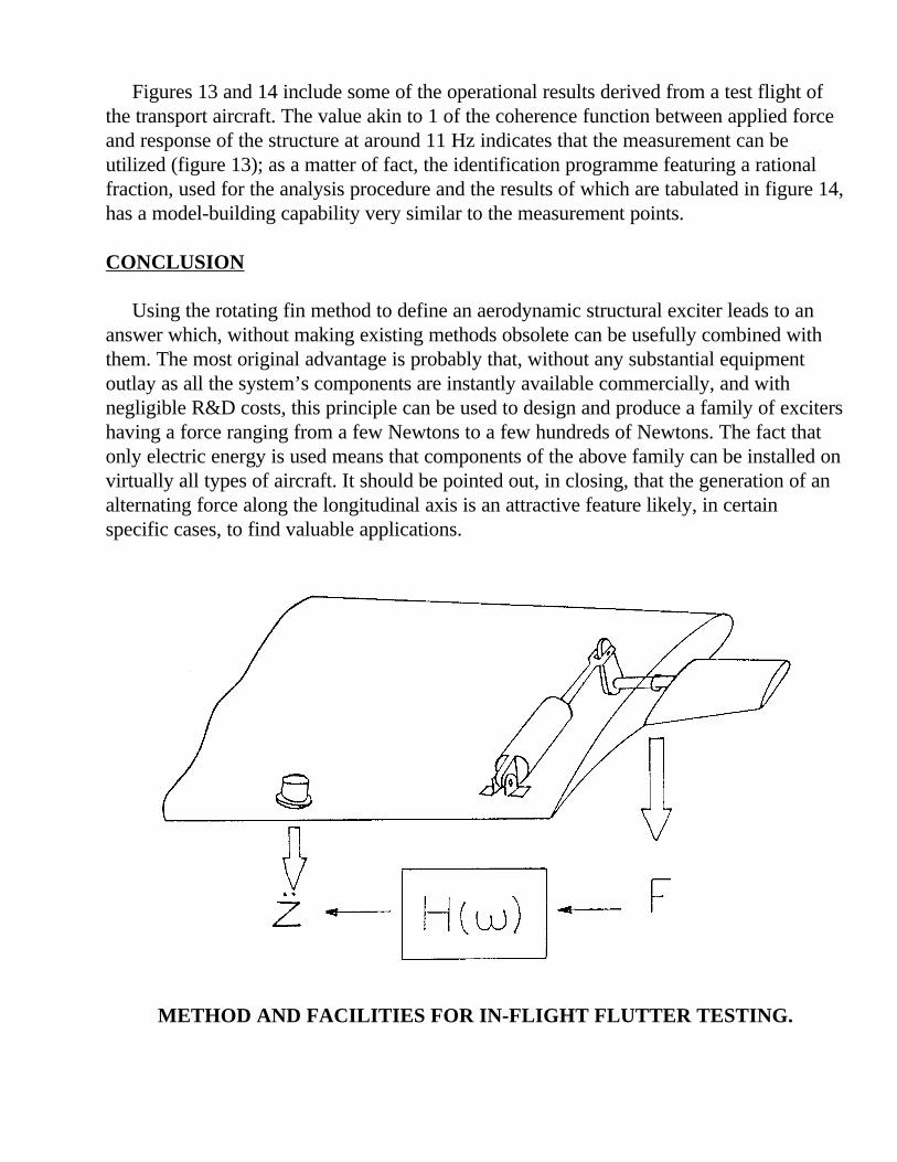
Using telemetering, as in conducting these tests, is beneficial in several respects(figure 2). First it allows instant visual monitoring of the structure’s behaviour at its mostsignificant points (rudders, bearing surface ends) by a team conveniently arranged on theground. Then, further to a preliminary processing operation occurring in real-time, the test
can be validated by merely observing the spectrums and the coherence functions existingbetween the forces applied and the structure’s response; a poor quality test, either due to amismatched excitation or to the unexpected effect of an atmospheric turbulence, can bererun without waiting for the aircraft to land. Finally, if adequate computing facilities areavailable, a comprehensive utilization of the values measured and their identification witha theoretical model lets the structure’s general behaviour be compared with the estimatedfigures, and thereby lets the aircraft resume the same test sequence at a higher speed orMach number. The accuracy of the result and the speed at which it is obtained, so essentialto the safe resumption of the flight, primarily depend on the extent and on the adequacy ofthe available information on the artificially applied forces. The design of “exciters”capable of creating controlled and measurable forces of an adequate level is thus the mostvital constraint of the flutter testing facility.
2 Principles of the “Colibri” exciters
Many alternatives have been suggested to answer this excitation issue. One of the mosteffective ones consists in using the aerodynamic lift forces appearing on a small auxiliarysurface actuated by a low-amplitude oscillating motion around a medium position havingno aerodynamic lift (Figure 1). In such a motion, and even for an aerodynamically andmechanically balanced fin, the development of inertial torques with the square of thefrequency results in the use of substantial powers. Thus, in the testing facilities available todate hydraulic energy is used in most cases so as to take advantage of the excellentrelationship between the power and the weight of hydraulic motors. Exciters based on thissystem attain a very high degree of efficiency but are not easily compatible with allcircumstances. The need to have hydraulic energy available at the exciter installation point,the quality of the construction of the mechanism and of the fin result in costs andavailability times which are often substantial.
It’s probably for these reasons that the installation of this type of exciters has never, toour knowledge, ever been attempted. Light aircraft in-flight testing is therefore performedwith other facilities the most widespread of which being the pyrotechnic pulser. On firingthe pulser, the structure is displaced from its point of balance, its transfer function beingestimated by the analysis of its return to the balance position. One of this procedure’sdrawbacks is to cancel out part of the benefits provided by the use of telemetering:validating the test in real-time is not very valuable, and even less its complete utilization -since in any case the aircraft has to be landed as the pulser is not rechargeable.
In attempting to apply to all types of aircraft, initially thinking of light aircraft, aprocedure and facilities which had been proven on fighter and wide-body aircraft, theC.E.V.(I-F.T.C.)and O.N.E.R.A. have designed a range of aerodynamic exciters cheaperand easier to use than conventional oscillating-fin exciters.
The straightforward idea was to actuate the moving surface with a permanent rotatingmotion around its middle centreline, in order to cut the power needed to set the system inmotion and thus to enable the use of an electric motor. The aerodynamic efficiency wouldprobably be poor but on the other hand there would be a critical gain in the power to begenerated. What’s more, easy mechanical design resulted in minimal exciter dead weight.This of course is an important point as the fineness characteristic of the exciter as a testinstrument, measured by comparing the force delivered with the total weight, must be ashigh as possible, 1 being a minimum value currently obtainable with electro-inertialsystems.
To find a really reliable and effective answer the following requirements also have to bemet:
- it must be possible to drive several exciters via a single control device in order todeliver synchronized forces.
- the dynamic effort applied to the structure by each exciter must be available and mustform an accurate input value.
- the exciters as a whole must not add to the structure another degree of liberty liable tointroduce a coupling unrelated to the flutter problem.
- finally: the exciter unit’s technology must make use of widely distributed componentsallowing them to be promptly fitted to various sizes of aircraft and for different flightconditions.
3 -GENERAL ARRANGEMENT
The problem set out in the foregoing paragraphs led to the adoption of the followingdesign of an in-flight excitation system christened “Colibri” (Humming Bird).
- The motor used is a step type motor affording from one and the same command signalan angular and synchronous displacement of exciters placed in different parts of theaircraft. This motor has two shaft outputs symmetrically driving directly: two identicalfins in a cantilever assembly (figure 3). This motor/fins unit is linked to the structure bya dynamometric sole-plate consisting of 3 piezoelectric force sensors mountedmechanically and electrically in parallel and thus measuring, projected onto theinstallation axis, the sum of the aerodynamic and inertial forces applied by the exciterto the structure under study.
With rotating fins, unlike oscillating vanes in which the force level can be adjusted byvarying the backlash amplitude, the only way to modify the force amplitude at a givendynamic pressure is to modify the area of the fins. Experience has shown that tomaintain a force of a substantially constant level three or four sets of fins in decreasingsizes were needed.
- The drive mechanism is, in principle, extremely straightforward (figure 4). The rotationspeed of the motors is imposed by an oscillator giving a signal which variescontinuously in frequency between 2 limits, high and low, which are displayed togetherwith the choice of the duration of this sweeping motion. The signal is applied to a fixeddivider for the master motor and to variable dividers for the slave motors. Thesevariable dividers are meant to put the slave motors in phase or in opposition, byaccelerating or decelerating the slave motors at the start sequence; in steady-stateoperation, all the dividers agree with the value representing the master motor, the step-motor principle guaranteeing the holding of the relative initialised phases.
4 - MODEL-BUILDING, PRELIMINARY TESTS
Determining the dimensions of the fins and the capacity of the motor in terms of theforce required and of the aerodynamic flight parameters would require either a theoreticalmodel-building or, at the very least, a few experimental data relating to that aerodynamiccuriosity that is a wing rotating around its middle axis.
Since as yet there have been no practical applications, this subject has virtually nohistorical precedent apart from some work carried out on the autorotation system which isa stable operating rate at high angular speed and is quite out of the scope of the presentarea of application.
Readings taken in wind-tunnels (S 1 L and S 2 at the O.N.E.R.A.) (on a LOCKHEEDT 33 at the French In-Flight Testing Centre - figure 5), helped to a certain extent completethe insufficiencies of the estimation and to formulate simple relationships which wereneeded to define the fins and their motor.
In one complete rotational movement, lift and drag factors Cz and Cx becomeperiodical, almost sinewave functions the peak amplitude of which is almost the value 1and increases as the frequency drops (ratio of the fin’s peripheral speed to the airspeed ininfinity). This amplitude is not very dependent on the elongation of the fin, as shown infigure 6 - at least up to the Mach number - 0.8 - actually explored. Figure 7 shows thechanges in the alternating part of Cx, Cz and of moment factor Cm. It will be noted thatthe harmonics ratio is low on the forces but high on the moment; this does not howeverincrease the signal’s peak factor. The relative phase between the three parameters remains
approximately constant, and in particular the drag factor shows a constant phase delay of/2 compared with the lift. The generated force is thus a rotating vector of virtually constantamplitude. This characteristic may be used to study modes having a high longitudinalparticipation such as the coplanar modes. The high Cz values reached lead to the choice offins with a fairly small area. Since the profiled form of these particular fins probably onlyhas a very secondary influence, they will be extremely easy to make. The models tested atthe C.E.V. (I-F.T.C.) simply consisted of ordinary metal or composite material plate cutout to the desired shape.
The torque needed to maintain a constant angular fin speed is either motive or resistant,and the motor has to be able to impose its speed along both axes. This torque is, roughlyspeaking, proportional to the lift force with an influence, found to be low, of the planar fin,the Mach number and the frequency. Thus, the torque characteristic, in terms of the motorrotation speed, provides on its own the force characteristic in terms of the exciterfrequency, unaffected by the aerodynamic conditions.
The few experimental results given in the foregoing paragraphs help define with anacceptable approximation the area of the fins and the specification of the motor to besupplied to build an exciter having a given force in the flight and frequency envelope understudy.
5 - RESULTS ON AIRCRAFT IN FLIGHT
The French In-Flight Tests Centre and O.N.E.R.A. have built two “Colibri” units on thebases stated above: a. a low-power unit designed to validate the method by in-flight testinga light aircraft, b. a medium-power unit for an actual test on a large military transportaircraft modified by the installation of pods under its wings. The force/frequencycharacteristics of the exciters used in both cases are given in figure 8. Figure 9 shows thecomponents of the unit designed for the transport aircraft. The large electronic power unit,shown on the right-hand side, is necessary for accurately regulating the step motor; thispower unit can be at a distance from the motor (in our specific application, about20 metres) and be installed in the fuselage: its bulk is therefore, as a rule, only a minordrawback. In the foreground are shown the four types of fins covering a speed envelope of150 to 350 knots. Figures 10 to 12 show the installation of the exciters on both aircraft, thecompactness of the exciter compared with the aircraft’s dimensions being specificallynoticeable in connection with the transport aircraft.
Figure 2 shows that given the specific position of the pod added to the aircraft, theexciter’s capability to deliver a drag force may be used to study wing twist modes whichare often involved in flutter instabilities.
Figures 13 and 14 include some of the operational results derived from a test flight ofthe transport aircraft. The value akin to 1 of the coherence function between applied forceand response of the structure at around 11 Hz indicates that the measurement can beutilized (figure 13); as a matter of fact, the identification programme featuring a rationalfraction, used for the analysis procedure and the results of which are tabulated in figure 14,has a model-building capability very similar to the measurement points.
CONCLUSION
Using the rotating fin method to define an aerodynamic structural exciter leads to ananswer which, without making existing methods obsolete can be usefully combined withthem. The most original advantage is probably that, without any substantial equipmentoutlay as all the system’s components are instantly available commercially, and withnegligible R&D costs, this principle can be used to design and produce a family of excitershaving a force ranging from a few Newtons to a few hundreds of Newtons. The fact thatonly electric energy is used means that components of the above family can be installed onvirtually all types of aircraft. It should be pointed out, in closing, that the generation of analternating force along the longitudinal axis is an attractive feature likely, in certainspecific cases, to find valuable applications.
METHOD AND FACILITIES FOR IN-FLIGHT FLUTTER TESTING.
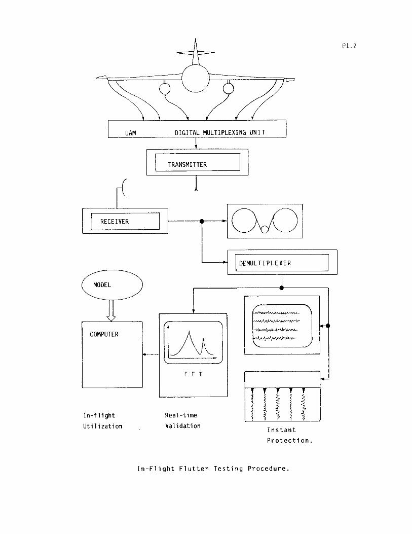
Rotating Aerodynamic Exciter
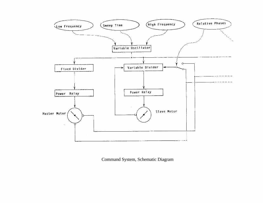
Command System, Schematic Diagram
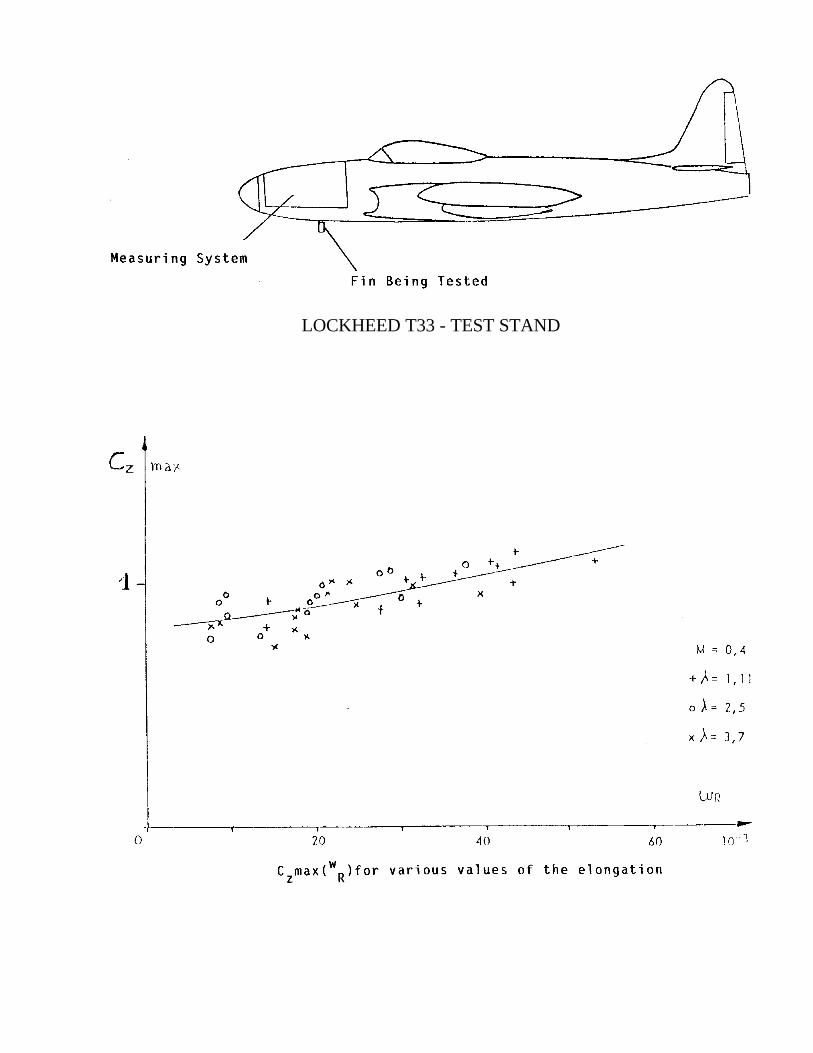
LOCKHEED T33 - TEST STAND
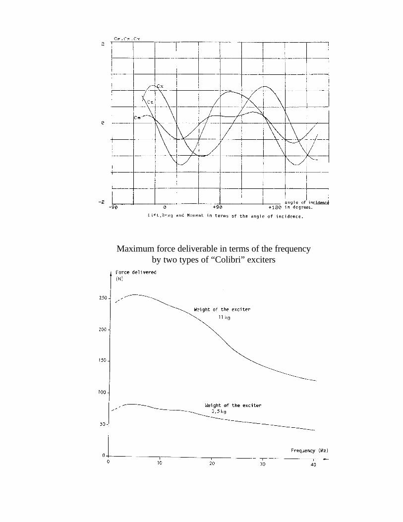
Maximum force deliverable in terms of the frequencyby two types of “Colibri” exciters
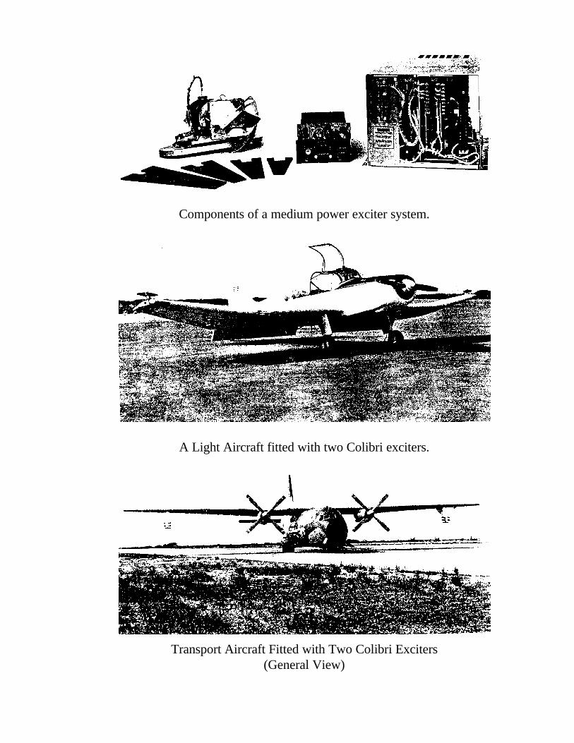
Components of a medium power exciter system.
A Light Aircraft fitted with two Colibri exciters.
Transport Aircraft Fitted with Two Colibri Exciters(General View)
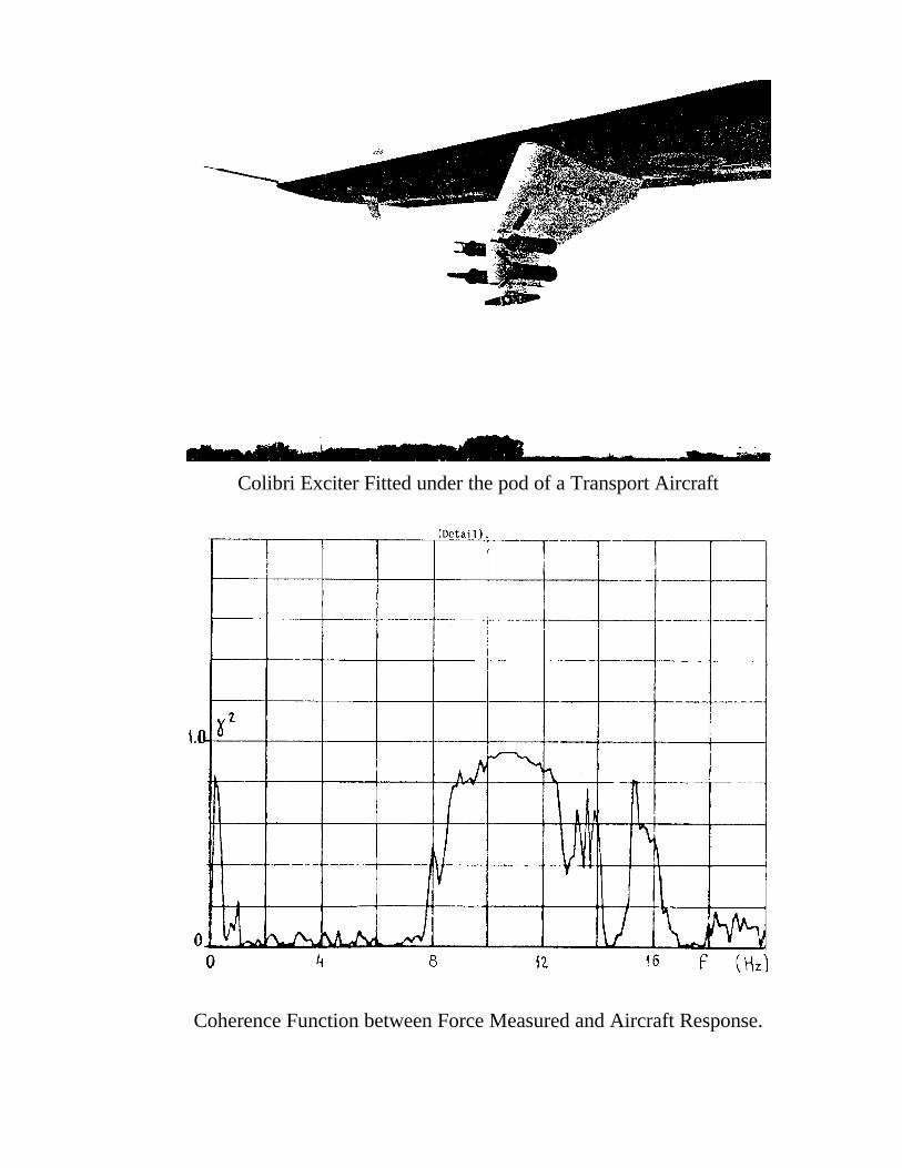
Colibri Exciter Fitted under the pod of a Transport Aircraft
Coherence Function between Force Measured and Aircraft Response.
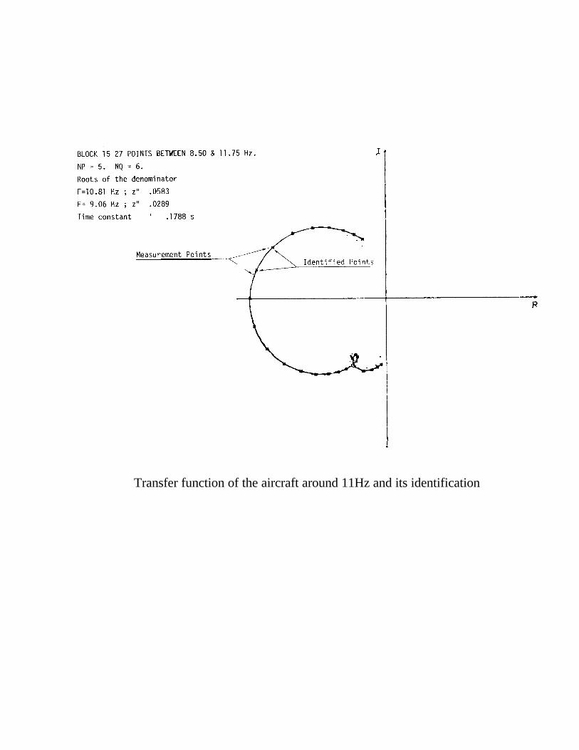
Transfer function of the aircraft around 11Hz and its identification