Embed Size (px)
Citation preview
1
Abstract
Paper contains the results of experimental
data assessment for open rotor COMBY2 model
developed in CIAM (open rotor COMBY1 model
has been developed by CIAM in frame of
European project DREAM). Comparison
between experimental results and aerodynamic
and acoustic calculations executed by means of
software developed in CIAM is presented. Comparison of integral characteristics
(absolute values of thrust and torque, thrust
coefficients, power coefficient and Open Rotors
efficiency) and local parameters of the flow
(radial distributions of flow parameters
downstream and upstream the rotors, pressure
distribution on hub downstream and upstream
the rotors) is carried out for aerodynamic
performances. The analysis of numerical and
experimental results shows good qualitative
coincidence.
At the same time it is possible to consider
quantitative coincidence only satisfying,
especially for integral characteristics (thrust
coefficient, power coefficient and efficiency). The
reason of notable disagreement between
calculation and experiment, probably, is the
difficulties in definition of forces and torques
acting on hub of each rotor. These values should
be taken away from experimental data to get
forces and torques acting only on blades for
which calculation data is obtained.
Calculation of acoustic characteristics of
open rotor models has been performed by means
of CIAM software 3DAS. Pulsation fields in near
field, directivity diagrams and spectrums in far
field have been obtained. Comparison of
calculated and experimental data is also
presented for acoustic characteristics.
Nomenclature
CRF – Counter-Rotating Fan;
CROR – Counter-Rotating Open Rotor;
GTF – Geared Turbofan;
BPF1 – 1st Blade Passing Frequency;
BPF2 – 2nd
Blade Passing Frequency;
V – flight velocity;
n – rotation frequency;
D – outer diameter of the rotor (front row);
nD
VJ – rotor pitch;
42 Dn
FC N
T
– thrust coefficient;
53 Dn
PwC p
– power coefficient;
Pw
VFE N
f
* – efficiency;
Ef=Ef /*ad, – dimensionless quantity of
efficiency;
Ef1,Ef2,Ef1&f2 – dimensionless quantity of
efficiency of first rotor, second rotor and open
rotor as a whole;
*ad – adiabatic efficiency in specification TOC;
TOC – Top of Climb mode;
Mf – inlet Mach number.
ASSESSMENT OF AERODYNAMIC AND ACOUSTIC CHARACTERISTICS OF COUNTER-ROTATING OPEN
ROTORS Igor Brailko*, Victor Mileshin*, Anton Rossikhin*
*Central Institute of Aviation Motors, 2, Aviamotornaya str. 111116, Moscow, Russia
Keywords: aerodynamic performances, noise, counter rotating fan, open rotor
MILESHIN V., BRAILKO I., ROSSIKHIN A.
2
1. Introduction
One of perspective direction in aviation
propulsion engineering is the development of
turbofans with counter-rotating open rotors. Such
engines have high fuel efficiency. Calculations
have shown that economy of liquid fuel during
cargo transportation by aircraft equipped with
such engine can make 20%30% in comparison
with fuel consumption of modern aircraft
powered by turbofan engine. At the same time
CRF engines have some peculiar disadvantages,
in particular, higher noise levels vs turbofan
engines with high and ultrahigh bypass ratio with
similar characteristics.
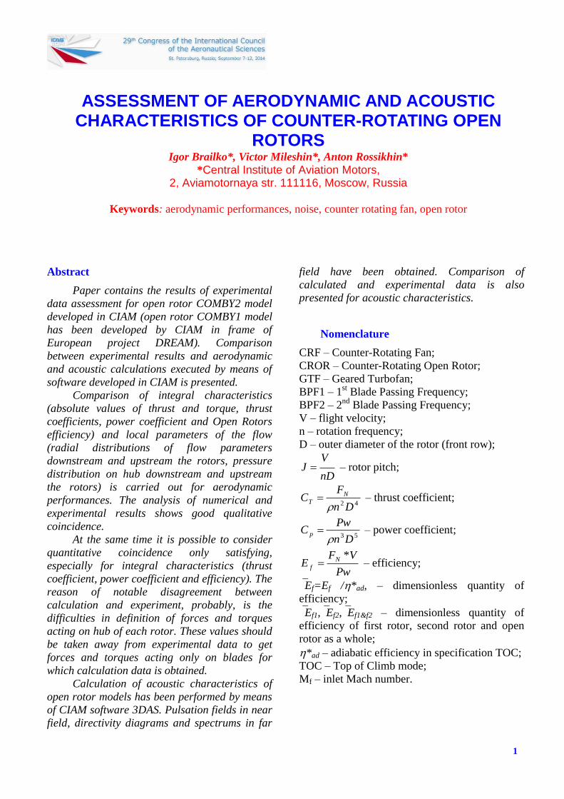
In the given work it is presented the
aerodynamic and acoustic optimization for the
model of COMBY2 open rotor (fig. 1) on base of
CFD and САА software, developed in CIAM.
Version V2.0 of pusher type OR developed in
frames of European project DREAM [1-3] was
taken as initial prototype of OR.
Aerodynamic optimization was performed
both for the purpose of increasing the efficiency,
and for improvement of OR acoustic
characteristics. For this purpose it was done the
smoothing of aerodynamic loading along blade
chord by cutting of its peaks near leading edges.
Besides, it was performed the redistribution of
aerodynamic loading on height of OR blades by
unloading blade tip sections and loading of mid
sections. Such ideology of aerodynamic and
acoustic characteristics improvement has been
developed in [4]. Redesign of OR blades by
obtained modified loading was done on the basis
of 3D inverse problem solution [5].
In order to decrease the intensity of tip
vortexes and their interaction it was used rotor
clipping (reduction of second rotor diameter by
21.3 %).
When design and optimization works have
been finished, model blades of COMBY2 OR
have been manufactured and tested at TsAGI:
aerodynamic and acoustic characteristics of
COMBY2 on takeoff and landing modes have
been investigated in subsonic wind-tunnel Т-104
at Mach numbers for inlet flow М=0.150.25,
and in transonic wind-tunnel Т-107 it has been
studied aerodynamic and acoustic characteristics
for climb and cruise modes.
Fig. 1. Research project of pusher type OR
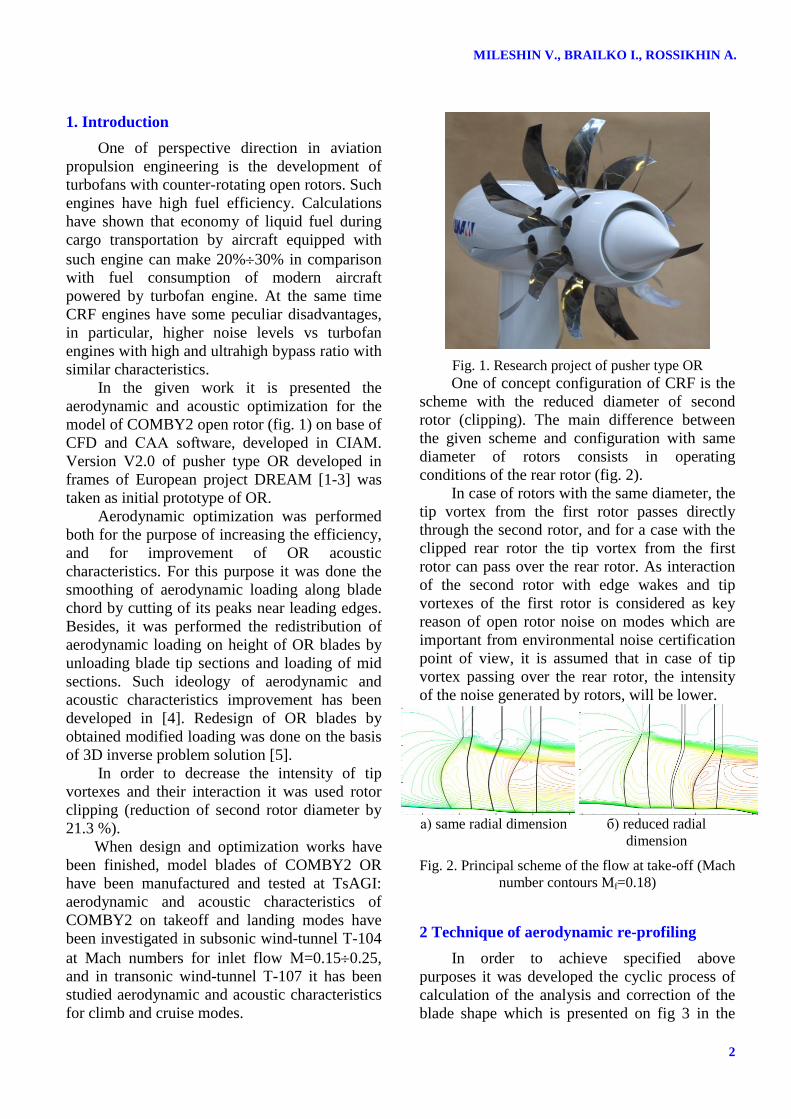
One of concept configuration of CRF is the
scheme with the reduced diameter of second
rotor (clipping). The main difference between
the given scheme and configuration with same
diameter of rotors consists in operating
conditions of the rear rotor (fig. 2).
In case of rotors with the same diameter, the
tip vortex from the first rotor passes directly
through the second rotor, and for a case with the
clipped rear rotor the tip vortex from the first
rotor can pass over the rear rotor. As interaction
of the second rotor with edge wakes and tip
vortexes of the first rotor is considered as key
reason of open rotor noise on modes which are
important from environmental noise certification
point of view, it is assumed that in case of tip
vortex passing over the rear rotor, the intensity
of the noise generated by rotors, will be lower.
а) same radial dimension б) reduced radial
dimension
Fig. 2. Principal scheme of the flow at take-off (Mach
number contours Mf=0.18)
2 Technique of aerodynamic re-profiling
In order to achieve specified above
purposes it was developed the cyclic process of
calculation of the analysis and correction of the
blade shape which is presented on fig 3 in the
3
ASSESSMENT OF AERODYNAMIC AND ACOUSTIC CHARACTERISTICS OF
COUNTER-ROTATING OPEN ROTORS
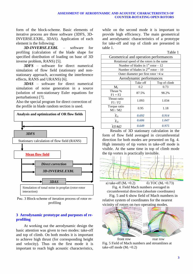
form of the block-scheme. Basic elements of
iterative process are three software (3DFS, 3D-
INVERSE.EXBL, 3DAS). Application of each
element is the following:
3D-INVERSE.EXBL – software for
profiling (calculation of the blade shape for
specified distribution of loading on base of 3D
inverse problem, RANS) [5].
3DFS – software for direct numerical
simulation of flow field (stationary and non-
stationary approach, accounting the interference
effects, RANS and URANS) [6].
3DAS – software for direct numerical
simulation of noise generation in a source
(solution of non-stationary Euler equations for
perturbations) [7].
Also the special program for direct correction of
the profile in blade random section is used.
Рис. 3 Block-scheme of iteration process of rotor re-
profiling
3 Aerodynamic prototype and purposes of re-
profiling
At working out the aerodynamic design the
basic attention was given to two modes: take-off
and top of climb. On both modes it is important
to achieve high thrust (for corresponding height
and velocity). Thus on the first mode it is
important to reach high acoustic characteristics,
while on the second mode it is important to
provide high efficiency. The main geometrical
and aerodynamic characteristics of a prototype
for take-off and top of climb are presented in
table 1.
Table 1
Geometrical and operation performances Rotational speed of the rotors is the same
Number of blades in 1st rotor – 12
Number of blades in 2nd
rotor – 10
Outer diameter per first rotor >4 м
Aerodynamic performances Take off Top of climb
Mf 0.2 0.73
Thrust %
F1 + F2 87.5% 98.2%
Thrust ratio
F1 / F2 1.093 1.034
Torque ratio
M1 / M2 0.95 1.18
Ef1 0.692 0.914
Ef2 0.606 1.047
Ef1&f2 0.649 0.975
Results of 3D stationary calculation in the
form of flow field averaged in circumferential
direction for both modes are presented on fig. 4.
High intensity of tip vortex in take-off mode is
visible. At the same time in top of climb mode
the tip vortex is practically invisible.
а) take-off (Mf =0.2) б) TOC (Mf =0.73)
Fig. 4. Field Mach numbers averaged in
circumferential direction (absolute coordinates)
Fig. 5 and 6 show field of Mach numbers in
relative system of coordinates for the nearest
vicinity of rotors on two operating modes.
front row rear row
Fig. 5 Field of Mach numbers and streamlines at
take-off mode (Mf =0.2)
Stationary calculation of flow field (RANS)
Analysis and optimization of OR flow fields
3DFS
3DAS
Mean flow field
Direct correction
3D-INVERSE.EXBL
Simulation of tonal noise in propfan (rotor-rotor
interaction)
MILESHIN V., BRAILKO I., ROSSIKHIN A.
4
front row rear row
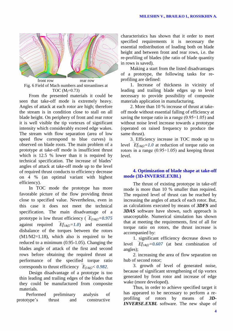
Fig. 6 Field of Mach numbers and streamlines at
TOC (Mf=0.73)
From the presented materials it could be
seen that take-off mode is extremely heavy.
Angles of attack at each rotor are high; therefore
the stream is in condition close to stall on all
blade height. On periphery of front and rear rotor
it is well visible the tip vortexes of significant
intensity which considerably exceed edge wakes.
The stream with flow separation (area of low
speed flow correspond to blue curves) is
observed on blade roots. The main problem of a
prototype at take-off mode is insufficient thrust
which is 12.5 % lower than it is required by
technical specification. The increase of blades’
angles of attack at take-off mode up to the level
of required thrust conducts to efficiency decrease
on 4 % (an optimal variant with highest
efficiency).
In TOC mode the prototype has more
favorable picture of the flow providing thrust
close to specified value. Nevertheless, even in
this case it does not meet the technical
specification. The main disadvantage of a
prototype is low thrust efficiency (Ef1&f2=0.975
against required Ef1&f2=1.0) and essential
disbalance of the torques between the rotors
(М1/М2=1.18), which also is required to be
reduced to a minimum (0.95-1.05). Changing the
blades angle of attack of the first and second
rows before obtaining the required thrust at
performance of the specified torque ratio
corresponds to thrust efficiency Ef1&f2< 0.982.
Design disadvantage of a prototype is too
thin leading and trailing edges of the blades that
they could be manufactured from composite
materials.
Performed preliminary analysis of
prototype’s thrust and constructive
characteristics has shown that it order to meet
specified requirements it is necessary the
essential redistribution of loading both on blade
height and between front and rear rows, i.e. the
re-profiling of blades (the ratio of blade quantity
in rows is saved).
Making a start from the listed disadvantages
of a prototype, the following tasks for re-
profiling are defined:
1. Increase of thickness in vicinity of
leading and trailing blade edges up to level
necessary to provide possibility of composite
materials application in manufacturing.
2. More than 10 % increase of thrust at take-
off mode without essential falling of efficiency at
saving the torque ratio in a range (0.95÷1.05) and
without noise level increase towards a prototype
(operated on raised frequency to produce the
same thrust).
3. Efficiency increase in TOC mode up to
level Ef1&f2=1.0 at reduction of torque ratio on
rotors in a range (0.95÷1.05) and keeping thrust
level.
4. Optimization of blade shape at take-off
mode (3D-INVERSE.EXBL)
The thrust of existing prototype in take-off
mode is more than 10 % smaller than required.
The required level of thrust can be reached by
increasing the angles of attack of each rotor. But,
as calculations executed by means of 3DFS and
3DAS software have shown, such approach is
unacceptable. Numerical simulation has shown
that at meeting the requirements, first of all for
torque ratio on rotors, the thrust increase is
accompanied by:
1. significant efficiency decrease down to
level Ef1&f2=0.607 (at best combination of
angles);
2. increasing the area of flow separation on
hub of second rotor;
3. growth of level of generated noise,
because of significant strengthening of tip vortex
generated by front rotor and increase of edge
wake (more developed).
Thus, in order to achieve specified target it
has appeared to be necessary to perform a re-
profiling of rotors by means of 3D-
INVERSE.EXBL software. The new shape of
5
ASSESSMENT OF AERODYNAMIC AND ACOUSTIC CHARACTERISTICS OF
COUNTER-ROTATING OPEN ROTORS
blades is found as result of 3D inverse problem
solution, providing calculation of blade shape for
specified distribution of loading in radial and
longitudinal direction (additionally it has been
redistributed the loading between rotors). Thus,
not only loading on blades has been increased,
but also its redistribution along profile chords
has been made. In particular, for improvement of
acoustic and aerodynamic properties, the loading
maximum has been moved from blade leading
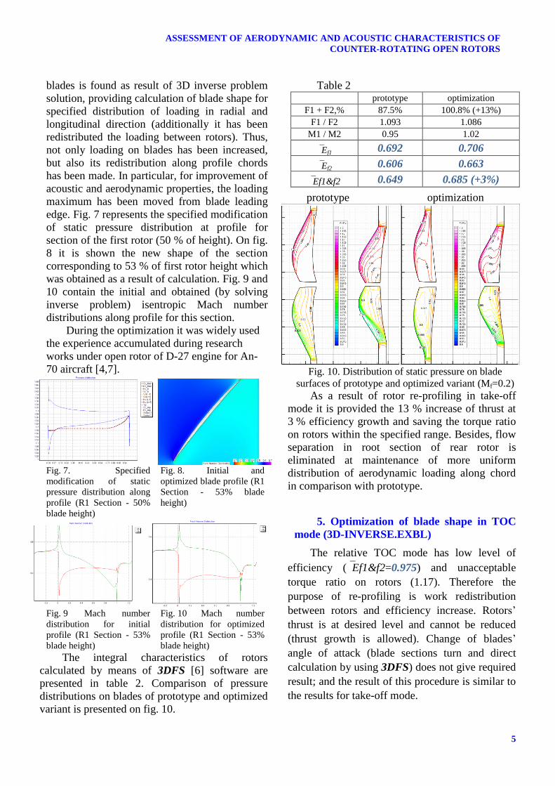
edge. Fig. 7 represents the specified modification
of static pressure distribution at profile for
section of the first rotor (50 % of height). On fig.
8 it is shown the new shape of the section
corresponding to 53 % of first rotor height which
was obtained as a result of calculation. Fig. 9 and
10 contain the initial and obtained (by solving
inverse problem) isentropic Mach number
distributions along profile for this section.
During the optimization it was widely used
the experience accumulated during research
works under open rotor of D-27 engine for An-
70 aircraft [4,7].
Fig. 7. Specified
modification of static
pressure distribution along
profile (R1 Section - 50%
blade height)
Fig. 8. Initial and
optimized blade profile (R1
Section - 53% blade
height)
Fig. 9 Mach number
distribution for initial
profile (R1 Section - 53%
blade height)
Fig. 10 Mach number
distribution for optimized
profile (R1 Section - 53%
blade height)
The integral characteristics of rotors
calculated by means of 3DFS [6] software are
presented in table 2. Comparison of pressure
distributions on blades of prototype and optimized
variant is presented on fig. 10.
Table 2 prototype optimization
F1 + F2,% 87.5% 100.8% (+13%)
F1 / F2 1.093 1.086
M1 / M2 0.95 1.02
Ef1 0.692 0.706
Ef2 0.606 0.663
Ef1&f2 0.649 0.685 (+3%)
prototype optimization
Fig. 10. Distribution of static pressure on blade
surfaces of prototype and optimized variant (Mf=0.2)
As a result of rotor re-profiling in take-off
mode it is provided the 13 % increase of thrust at
3 % efficiency growth and saving the torque ratio
on rotors within the specified range. Besides, flow
separation in root section of rear rotor is
eliminated at maintenance of more uniform
distribution of aerodynamic loading along chord
in comparison with prototype.
5. Optimization of blade shape in TOC
mode (3D-INVERSE.EXBL)
The relative TOC mode has low level of
efficiency (Ef1&f2=0.975) and unacceptable
torque ratio on rotors (1.17). Therefore the
purpose of re-profiling is work redistribution
between rotors and efficiency increase. Rotors’
thrust is at desired level and cannot be reduced
(thrust growth is allowed). Change of blades’
angle of attack (blade sections turn and direct
calculation by using 3DFS) does not give required
result; and the result of this procedure is similar to
the results for take-off mode.
MILESHIN V., BRAILKO I., ROSSIKHIN A.
6
As well as in the previous section, for this
mode new distributions of loading on blades have
been defined and calculations of blade shape by
means of 3D-INVERSE.EXBL software have
been executed. In order to increase the efficiency,
Mach numbers before the shock wave located at
trailing edge have been reduced for both blades by
means of inverse problem. Besides, negative blade
loadings observed near leading edge have been
reduced for first rotor blades.
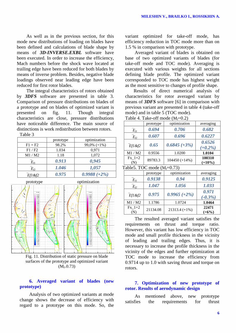
The integral characteristics of rotors obtained
by 3DFS software are presented in table 3.
Comparison of pressure distributions on blades of
a prototype and on blades of optimized variant is
presented on fig. 11. Though integral
characteristics are close, pressure distributions
have noticeable difference. The main source of
distinctions is work redistribution between rotors.
Table 3 prototype optimization
F1 + F2 98.2% 99,0% (+1%)
F1 / F2 1.034 0,971
M1 / M2 1.18 1,072
Ef1 0.913 0,945
Ef2 1.046 1,057
Ef1&f2 0.975 0.9988 (+2%)
prototype optimization
Fig. 11. Distribution of static pressure on blade
surfaces of the prototype and optimized variant
(Mf=0.73)
6. Averaged variant of blades (new
prototype)
Analysis of two optimized variants at mode
change shows the decrease of efficiency with
regard to a prototype on this mode. So, the
variant optimized for take-off mode, has
efficiency reduction in TOC mode more than on
1.5 % in comparison with prototype.
Averaged variant of blades is obtained on
base of two optimized variants of blades (for
take-off mode and TOC mode). Averaging is
executed with various weights for all sections
defining blade profile. The optimized variant
corresponded to TOC mode has highest weight
as the most sensitive to changes of profile shape.
Results of direct numerical analysis of
characteristics for rotor averaged variant by
means of 3DFS software [6] in comparison with
previous variant are presented in table 4 (take-off
mode) and in table 5 (TOC mode).
Table 4. Take-off mode (Mf=0.2) prototype optimization averaging
Ef1 0.694 0.706 0.682
Ef2 0.607 0.696 0.6227
Ef1&f2 0.65 0.6845 (+3%) 0.6526
(+0.2%) M1 / M2 0.9556 1.0200 1.0104
Fx_1+2
(N) 89783.3 104450 (+14%)
100310
(+10%)
Table5. TOC mode (Mf=0.73) prototype optimization averaging
Ef1 0.9138 0.94 0.9125
Ef2 1.047 1.056 1.033
Ef1&f2 0.975 0.9965 (+2%) 0.971
(-0.3%) M1 / M2 1.1786 1.0724 1.0464
Fx_1+2
(N) 21134.08 21313.4 (+1%)
22471
(+6%)
The resulted averaged variant satisfies the
requirements on thrust and torque ratio.
However, this variant has low efficiency in TOC
mode and small profile thickness in the vicinity
of leading and trailing edges. Thus, it is
necessary to increase the profile thickness in the
vicinity of the edges and further optimization at
TOC mode to increase the efficiency from
0.9714 up to 1.0 with saving thrust and torque on
rotors.
7. Optimization of new prototype of
rotor. Results of aerodynamic design
As mentioned above, new prototype
satisfies the requirements for thrust
7
ASSESSMENT OF AERODYNAMIC AND ACOUSTIC CHARACTERISTICS OF
COUNTER-ROTATING OPEN ROTORS
characteristics, but has small thickness of the
profile near edges and low efficiency in TOC
mode. TOC operation mode is extremely
sensitive to changes in the shape and blades
angle of attack. For this reason, further
optimization has been performed for TOC mode.
As a result of numerous iterations (which
will not be detailed discussed) in accordance
with block-scheme shown on Fig. 3, it has been
achieved the required level of aerodynamic
perfection for counter-rotating open rotors of
pusher type. Re-profiled blades have significant
differences from the original prototype,
including the following which should be noted:
1. profile thickness has been significantly
increased in the vicinity of the edges;
2. load in sections of the blades and thus the
shape and characteristic dimensions of control
sections have been redistributed;
3. work between the rotors has been
redistributed to keep the torque ratio at (0.95 ÷
1.05);
4. turning angles of the blades have been
reduced at transition from mode to mode.
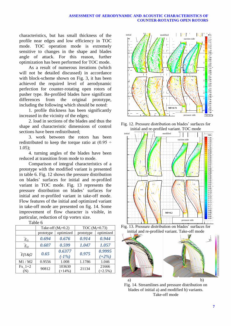
Comparison of integral characteristics of a
prototype with the modified variant is presented
in table 6. Fig. 12 shows the pressure distribution
on blades’ surfaces for initial and re-profiled
variant in TOC mode. Fig. 13 represents the
pressure distribution on blades’ surfaces for
initial and re-profiled variant in take-off mode.
Flow features of the initial and optimized variant
in take-off mode are presented on fig. 14. Some
improvement of flow character is visible, in
particular, reduction of tip vortex size.
Table 6 Take-off (Mf=0.2) TOC (Mf=0.73)
prototype optimized prototype optimized
Ef1 0.694 0.676 0.914 0.944
Ef2 0.607 0.599 1.047 1.057
Ef1&f2 0.65 0.6377
(-1%) 0.975
0.9995
(+2%) M1 / M2 0.9556 1.008 1.1786 1.046
Fx_1+2
(N) 90812
103630
(+14%) 21134
21666
(+2.5%)
сторона давления
сторона разряжения
исходный модифицированный
Мп=0.73
Fig. 12. Pressure distribution on blades’ surfaces for
initial and re-profiled variant. TOC mode
сторона давления
сторона разряжения
исходный модифицированный
Мп=0.2
Fig. 13. Pressure distribution on blades’ surfaces for
initial and re-profiled variant. Take-off mode
a) b)
Fig. 14. Streamlines and pressure distribution on
blades of initial a) and modified b) variants.
Take-off mode
modified initial
suction side
pressure side
Mf=0.73
suction side
pressure side
modified initial
Mf=0.2
MILESHIN V., BRAILKO I., ROSSIKHIN A.
8
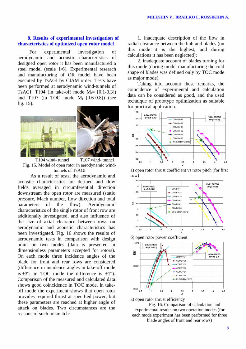
8. Results of experimental investigation of
characteristics of optimized open rotor model
For experimental investigation of
aerodynamic and acoustic characteristics of
designed open rotor it has been manufactured a
steel model (scale 1/6). Experimental research
and manufacturing of OR model have been
executed by TsAGI by CIAM order. Tests have
been performed at aerodynamic wind-tunnels of
TsAGI: Т104 (in take-off mode Mf= [0.1-0.3])
and Т107 (in TOC mode Mf=[0.6-0.8]) (see
fig. 15).
Т104 wind- tunnel Т107 wind- tunnel
Fig. 15. Model of open rotor in aerodynamic wind-
tunnels of TsAGI
As a result of tests, the aerodynamic and
acoustic characteristics are defined and flow
fields averaged in circumferential direction
downstream the open rotor are measured (static
pressure, Mach number, flow direction and total
parameters of the flow). Aerodynamic
characteristics of the single rotor of front row are
additionally investigated, and also influence of
the size of axial clearance between rows on
aerodynamic and acoustic characteristics has
been investigated. Fig. 16 shows the results of
aerodynamic tests in comparison with design
point on two modes (data is presented in
dimensionless parameters accepted for rotors).
On each mode three incidence angles of the
blade for front and rear rows are considered
(difference in incidence angles in take-off mode
is3 in TOC mode the difference is 1).
Comparison of the measured and calculated data
shows good coincidence in TOC mode. In take-
off mode the experiment shows that open rotor
provides required thrust at specified power; but
these parameters are reached at higher angle of
attack on blades. Two circumstances are the
reasons of such mismatch:
1. inadequate description of the flow in
radial clearance between the hub and blades (on
this mode it is the highest, and during
calculations it has been neglected);
2. inadequate account of blades turning for
this mode (during model manufacturing the cold
shape of blades was defined only by TOC mode
as major mode).
Taking into account these remarks, the
coincidence of experimental and calculation
data can be considered as good, and the used
technique of prototype optimization as suitable
for practical application.
0.2
0.4
0.6
0.8
1
1.2
1.4
1.6
0.5 1 1.5 2 2.5 3 3.5 4 4.5
J
CT
COMBY-41
COMBY-38
COMBY-35
COMBY-62
COMBY-61
COMBY-60
CT-COMBY // CFD
HIGH SPEED
M=[0.6-0.8]
LOW SPEED
M=[0.1-0.25]
а) open rotor thrust coefficient vs rotor pitch (for first
row)
0.5
1
1.5
2
2.5
3
3.5
4
4.5
0.5 1 1.5 2 2.5 3 3.5 4 4.5
J
CP
COMBY-41
COMBY-38
COMBY-35
COMBY-62
COMBY-61
COMBY-60
CP-COMBY // CFD
HIGH SPEED
M=[0.6-0.8]LOW SPEED
M=[0.1-0.25]
б) open rotor power coefficient
0.5
0.55
0.6
0.65
0.7
0.75
0.8
0.85
0.9
0.5 1 1.5 2 2.5 3 3.5 4 4.5
J
Ef
COMBY-41
COMBY-38
COMBY-35
COMBY-62
COMBY-61
COMBY-60
Ef-COMBY // CFD
LOW SPEED
M=[0.1-0.25]
HIGH SPEED
M=[0.6-0.8]
в) open rotor thrust efficiency
Fig. 16. Comparison of calculation and
experimental results on two operation modes (for
each mode experiment has been performed for three
blade angles of front and rear rows)
Eff
1.071
0.833
0.59
9
ASSESSMENT OF AERODYNAMIC AND ACOUSTIC CHARACTERISTICS OF
COUNTER-ROTATING OPEN ROTORS
9. The analysis of OR acoustic properties
For investigation of acoustic properties of
an open rotor in this work it has been applied
3DAS software developed in CIAM (3
Dimensional Acoustics Solver) [7-10].
3DAS software was used for investigation
of acoustic characteristics of open rotors in
DREAM project of 7th
European Frame
Program. In frames of the project for several
variants of open rotors it was performed the
comparison between the calculation directive
diagrams obtained by means of 3DAS software
and directive diagrams obtained by experiment.
Comparison between results of calculation and
experiment has shown that results of comparison
are satisfactory for noise on frequencies which
are the combinations of BPF1 and BPF2
harmonics. It is observed the qualitative and
quantitative (in some microphone positions)
coincidence between calculation and experiment.
The difference between noise levels on
harmonics of blade passing frequencies for
separate rotors in calculation and experiment is
significant. It, apparently, can be explained by
interactions of rotors during experiment with
inlet distortion of incident flow created by design
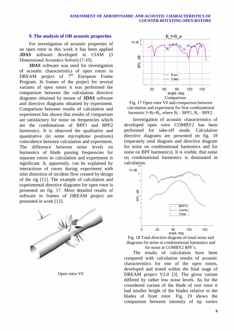
of the rig [11]. The example of calculation and
experimental directive diagrams for open rotor is
presented on fig. 17. More detailed results of
software in frames of DREAM project are
presented in work [12].
Open rotor V0
Comparison
Fig. 17 Open rotor V0 and comparison between
calculation and experiment for first combinational
harmonic f=Bf+Ba, where Bf – BPF1, Ba – BPF2.
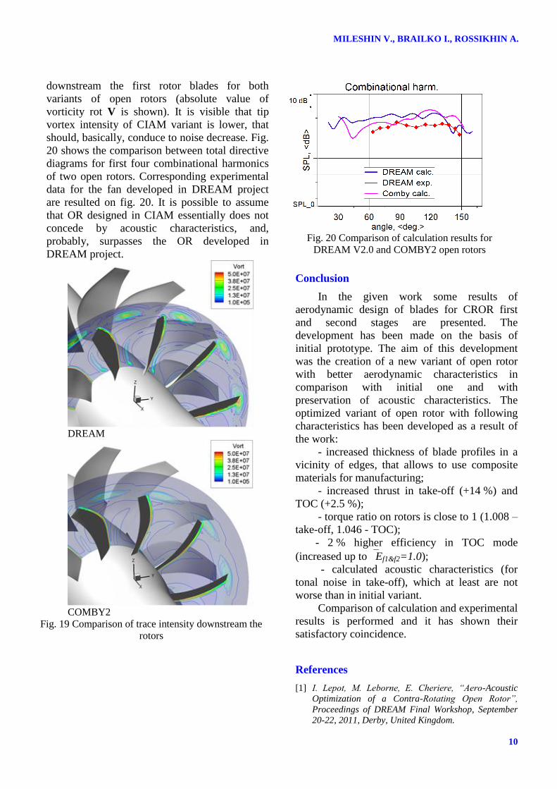
Investigation of acoustic characteristics of
developed open rotor COMBY2 has been
performed for take-off mode. Calculation
directive diagrams are presented on fig. 18
(separately total diagram and directive diagram
for noise on combinational harmonics and for
noise on BPF harmonics). It is visible, that noise
on combinational harmonics is dominated in
calculation.
Fig. 18 Total directive diagram of tonal noise and
diagrams for noise at combinational harmonics and
for noise at COMBY2 BPF’s.
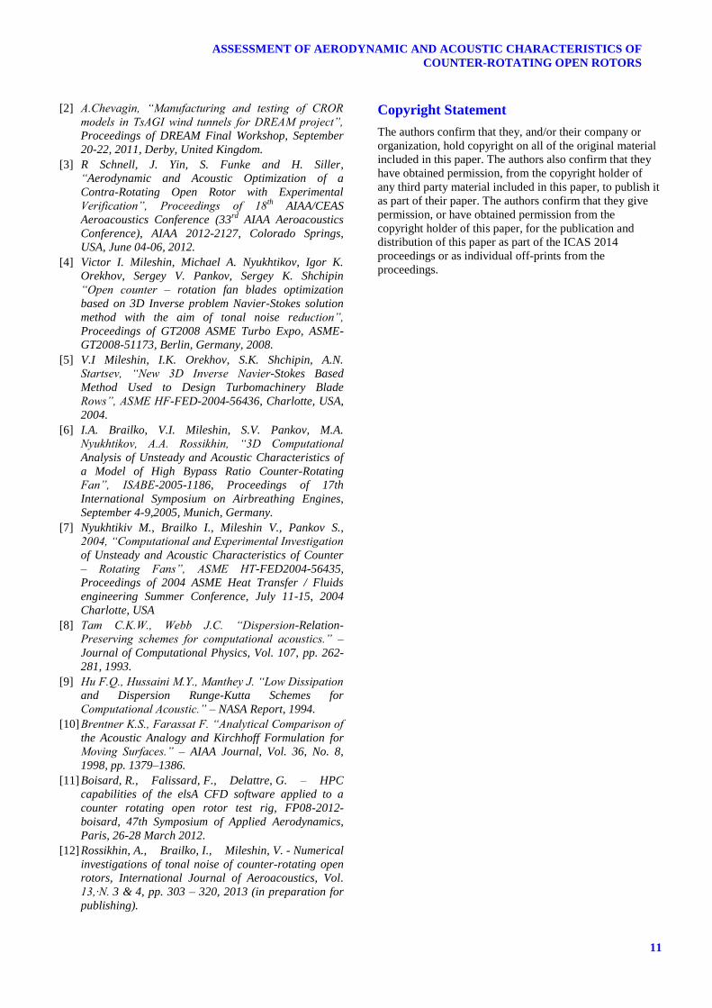
The results of calculation have been
compared with calculation results of acoustic
characteristics for one of the open rotors,
developed and tested within the final stage of
DREAM project V2.0 [3]. The given variant
differed by rather low noise levels. As for the
considered variant of the blade of rear rotor it
had smaller height of the blades relative to the
blades of front rotor. Fig. 19 shows the
comparison between intensity of tip vortex
MILESHIN V., BRAILKO I., ROSSIKHIN A.
10
downstream the first rotor blades for both
variants of open rotors (absolute value of
vorticity rot V is shown). It is visible that tip
vortex intensity of CIAM variant is lower, that
should, basically, conduce to noise decrease. Fig.
20 shows the comparison between total directive
diagrams for first four combinational harmonics
of two open rotors. Corresponding experimental
data for the fan developed in DREAM project
are resulted on fig. 20. It is possible to assume
that OR designed in CIAM essentially does not
concede by acoustic characteristics, and,
probably, surpasses the OR developed in
DREAM project.
DREAM
COMBY2
Fig. 19 Comparison of trace intensity downstream the
rotors
Fig. 20 Comparison of calculation results for
DREAM V2.0 and COMBY2 open rotors
Conclusion
In the given work some results of
aerodynamic design of blades for CROR first
and second stages are presented. The
development has been made on the basis of
initial prototype. The aim of this development
was the creation of a new variant of open rotor
with better aerodynamic characteristics in
comparison with initial one and with
preservation of acoustic characteristics. The
optimized variant of open rotor with following
characteristics has been developed as a result of
the work:
- increased thickness of blade profiles in a
vicinity of edges, that allows to use composite
materials for manufacturing;
- increased thrust in take-off (+14 %) and
TOC (+2.5 %);
- torque ratio on rotors is close to 1 (1.008 –
take-off, 1.046 - TOC);
- 2 % higher efficiency in TOC mode
(increased up to Ef1&f2=1.0);
- calculated acoustic characteristics (for
tonal noise in take-off), which at least are not
worse than in initial variant.
Comparison of calculation and experimental
results is performed and it has shown their
satisfactory coincidence.
References
[1] I. Lepot, M. Leborne, E. Cheriere, “Aero-Acoustic
Optimization of a Contra-Rotating Open Rotor”,
Proceedings of DREAM Final Workshop, September
20-22, 2011, Derby, United Kingdom.
11
ASSESSMENT OF AERODYNAMIC AND ACOUSTIC CHARACTERISTICS OF
COUNTER-ROTATING OPEN ROTORS
[2] A.Chevagin, “Manufacturing and testing of CROR
models in TsAGI wind tunnels for DREAM project”,
Proceedings of DREAM Final Workshop, September
20-22, 2011, Derby, United Kingdom.
[3] R Schnell, J. Yin, S. Funke and H. Siller,
“Aerodynamic and Acoustic Optimization of a
Contra-Rotating Open Rotor with Experimental
Verification”, Proceedings of 18th
AIAA/CEAS
Aeroacoustics Conference (33rd
AIAA Aeroacoustics
Conference), AIAA 2012-2127, Colorado Springs,
USA, June 04-06, 2012.
[4] Victor I. Mileshin, Michael A. Nyukhtikov, Igor K.
Orekhov, Sergey V. Pankov, Sergey K. Shchipin
“Open counter – rotation fan blades optimization
based on 3D Inverse problem Navier-Stokes solution
method with the aim of tonal noise reduction”,
Proceedings of GT2008 ASME Turbo Expo, ASME-
GT2008-51173, Berlin, Germany, 2008.
[5] V.I Mileshin, I.K. Orekhov, S.K. Shchipin, A.N.
Startsev, “New 3D Inverse Navier-Stokes Based
Method Used to Design Turbomachinery Blade
Rows”, ASME HF-FED-2004-56436, Charlotte, USA,
2004.
[6] I.A. Brailko, V.I. Mileshin, S.V. Pankov, M.A.
Nyukhtikov, A.A. Rossikhin, “3D Computational
Analysis of Unsteady and Acoustic Characteristics of
a Model of High Bypass Ratio Counter-Rotating
Fan”, ISABE-2005-1186, Proceedings of 17th
International Symposium on Airbreathing Engines,
September 4-9,2005, Munich, Germany.
[7] Nyukhtikiv M., Brailko I., Mileshin V., Pankov S.,
2004, “Computational and Experimental Investigation
of Unsteady and Acoustic Characteristics of Counter
– Rotating Fans”, ASME HT-FED2004-56435,
Proceedings of 2004 ASME Heat Transfer / Fluids
engineering Summer Conference, July 11-15, 2004
Charlotte, USA
[8] Tam C.K.W., Webb J.C. “Dispersion-Relation-
Preserving schemes for computational acoustics.” –
Journal of Computational Physics, Vol. 107, pp. 262-
281, 1993.
[9] Hu F.Q., Hussaini M.Y., Manthey J. “Low Dissipation
and Dispersion Runge-Kutta Schemes for
Computational Acoustic.” – NASA Report, 1994.
[10] Brentner K.S., Farassat F. “Analytical Comparison of
the Acoustic Analogy and Kirchhoff Formulation for
Moving Surfaces.” – AIAA Journal, Vol. 36, No. 8,
1998, pp. 1379–1386.
[11] Boisard, R., Falissard, F., Delattre, G. – HPC
capabilities of the elsA CFD software applied to a
counter rotating open rotor test rig, FP08-2012-
boisard, 47th Symposium of Applied Aerodynamics,
Paris, 26-28 March 2012.
[12] Rossikhin, A., Brailko, I., Mileshin, V. - Numerical
investigations of tonal noise of counter-rotating open
rotors, International Journal of Aeroacoustics, Vol.
13,·N. 3 & 4, pp. 303 – 320, 2013 (in preparation for
publishing).
Copyright Statement
The authors confirm that they, and/or their company or
organization, hold copyright on all of the original material
included in this paper. The authors also confirm that they
have obtained permission, from the copyright holder of
any third party material included in this paper, to publish it
as part of their paper. The authors confirm that they give
permission, or have obtained permission from the
copyright holder of this paper, for the publication and
distribution of this paper as part of the ICAS 2014
proceedings or as individual off-prints from the
proceedings.