Embed Size (px)
Citation preview
Data sheet DS/FPD500–EN Rev. F
OriMaster FPD500Compact orifice flowmeter
Measurement made easy
Orifice-based flow metering made simple
Integrated DP flow measurement system, pressure tested as an assembly— combines primary element with DP transmitter in a single
flowmeter assembly
Mass flow version with optional, integral temperature element— integral multivariable transmitter and RTD for direct reading
of mass (liquids and steam) and corrected volume (gas) flowrates in a single unit
Plugged impulse line detection— detects partial or complete blockage of DP connections— provides warnings visually and via outputs
Integral impulse connections— no impulse piping installation required— provides repeatable DP connection across installation
locations
Reduced installation costs— only one piece to install— eliminates need to supply and connect separate manifold,
transmitter and impulse piping
Easy to specify and maintain— single ordering code covers complete flowmeter— only two orifice ratios for simple specification process— optional replaceable orifice plates offer easy, economic
maintenance and flexibility for changing process conditions
New 'through-the-glass' (TTG) keypad technology— enables quick and easy local configuration without the need
to open the cover – even in hazardous areas
Factory acceptance report— supplied with report detailing results of critical inspection
checks, plus certification data

OriMaster FPD500Compact orifice flowmeter
2 DS/FPD500–ENsnRev. F | OriMaster FPD500 | Compact orifice flowmeter
OriMaster – the one-piece DP flowmeter
OriMaster is a stand-alone orifice-based flowmeter with a difference – its advanced design greatly simplifies installation and commissioning.
OriMaster incorporates the following features:— A wafer-bodied orifice carrier assembly with integral
square-edged, concentric plate and corner tapping points— Integral 3-valve manifold (optional 5-valve manifold
available)— Integral direct connections between the carrier tappings and
manifold— DP transmitter, factory-mounted onto the manifold and
pre-configured for the application— Fully leak-tested and configured
Benefits
OriMaster avoids many of the difficulties involved in the sizing, selection, procurement, installation and commissioning of conventional orifice plate installations.— With all the major components in one assembly, OriMaster
eliminates the problems of sourcing multiple components. Provides large savings in cost and time due to the simplicity of design and installation.
— Integral transmitter and manifold with compact tapping connections eliminates the need to run and connect impulse piping and offers:— guaranteed accuracy of positioning and installation of the
tapping points— reduced possibility of impulse line blockage
— The assembly is pressure-tested in the factory, giving the user confidence that the connections between the tapping points and the transmitter are completely free of leaks
— Factory configuration of the meter saves the user time during commissioning and ensures that the flowmeter output span truly matches that of the application flowrate
— Choice of two discrete Beta ratio values, together with the free sizing, selection and coding software, simplifies the sizing and selection process
— Optional design with replaceable orifice plates enables low-cost repair or, when process conditions change, re-ranging of the meter
— Element centralizing system ensures every meter is concentric with its pipe, thus avoiding significant additional metering errors
— New 'through-the-glass' (TTG) keypad technology enables meter configuration without terminals and with no need to remove the transmitter covers
OriMaster FPD500 | Compact orifice flowmeter | DS/FPD500–ENsnRev. F 3
Basic principle of operation
DP devices work on a principle based upon the Law of Conservation of Energy, where a restriction in the fluid path causes an acceleration in the fluid velocity with a corresponding increase in kinetic energy. The gain in kinetic energy is at the expense of pressure energy, resulting in a drop in fluid pressure across the narrowest part of the restriction. The drop in pressure and the flow rate are linked by the following (simplified) relationship:
Q = k DP
where Q = fluid flow rate
k = a constant for that DP device
DP = the pressure difference across the restriction
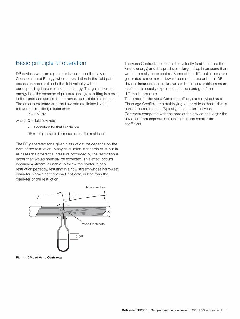
The DP generated for a given class of device depends on the bore of the restriction. Many calculation standards exist but in all cases the differential pressure produced by the restriction is larger than would normally be expected. This effect occurs because a stream is unable to follow the contours of a restriction perfectly, resulting in a flow stream whose narrowest diameter (known as the Vena Contracta) is less than the diameter of the restriction.
The Vena Contracta increases the velocity (and therefore the kinetic energy) and this produces a larger drop in pressure than would normally be expected. Some of the differential pressure generated is recovered downstream of the meter but all DP devices incur some loss, known as the 'irrecoverable pressure loss'; this is usually expressed as a percentage of the differential pressure.To correct for the Vena Contracta effect, each device has a Discharge Coefficient; a multiplying factor of less than 1 that is part of the calculation. Typically, the smaller the Vena Contracta compared with the bore of the device, the larger the deviation from expectations and hence the smaller the coefficient.
Fig. 1: DP and Vena Contracta
PP
DP
Vena Contracta
Pressure loss
OriMaster FPD500Compact orifice flowmeter
4 DS/FPD500–ENsnRev. F | OriMaster FPD500 | Compact orifice flowmeter
Versions
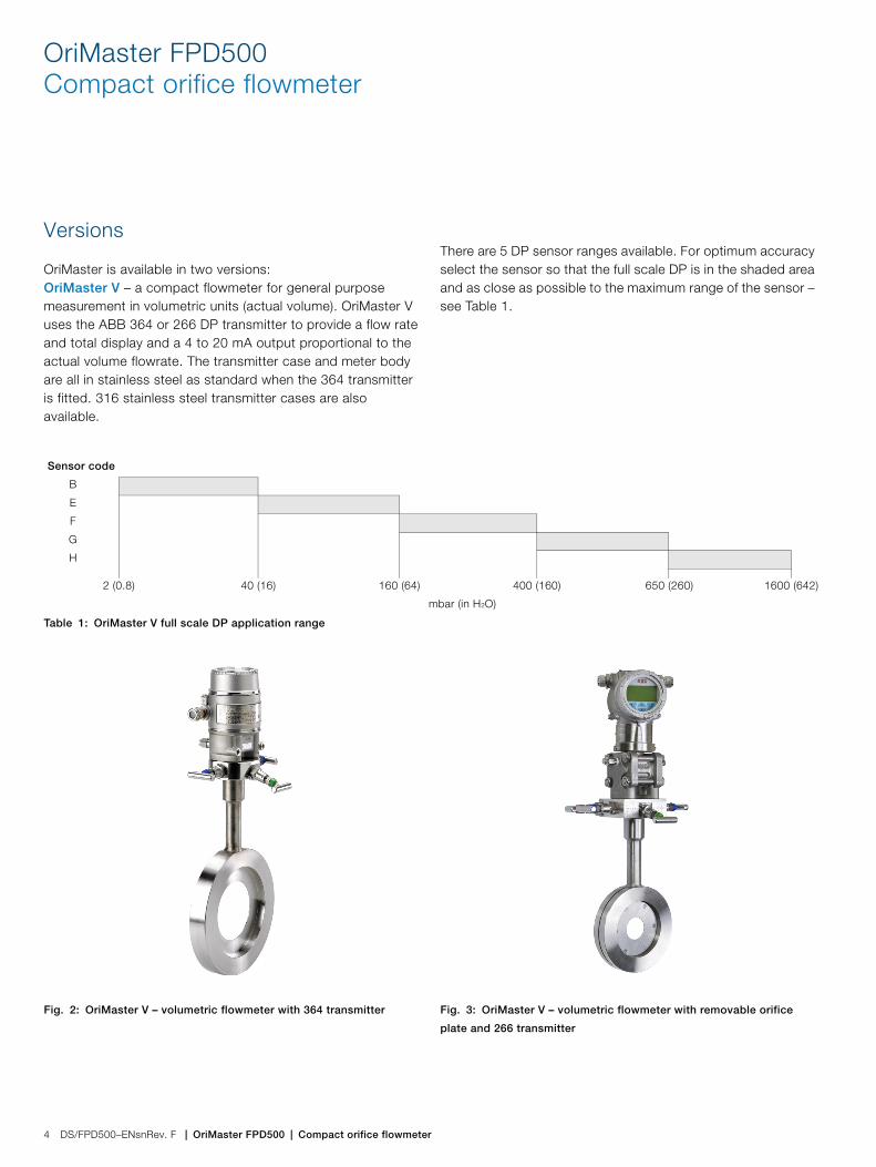
OriMaster is available in two versions:OriMaster V – a compact flowmeter for general purpose measurement in volumetric units (actual volume). OriMaster V uses the ABB 364 or 266 DP transmitter to provide a flow rate and total display and a 4 to 20 mA output proportional to the actual volume flowrate. The transmitter case and meter body are all in stainless steel as standard when the 364 transmitter is fitted. 316 stainless steel transmitter cases are also available.
There are 5 DP sensor ranges available. For optimum accuracy select the sensor so that the full scale DP is in the shaded area and as close as possible to the maximum range of the sensor – see Table 1.
Sensor code
B
E
F
G
H
2 (0.8) 40 (16) 160 (64) 400 (160) 650 (260) 1600 (642)
mbar (in H2O)
Table 1: OriMaster V full scale DP application range
Fig. 2: OriMaster V – volumetric flowmeter with 364 transmitter Fig. 3: OriMaster V – volumetric flowmeter with removable orifice
plate and 266 transmitter
OriMaster FPD500 | Compact orifice flowmeter | DS/FPD500–ENsnRev. F 5
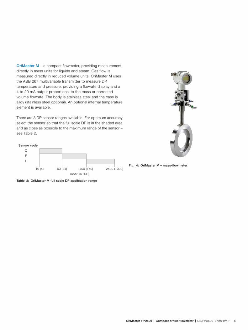
OriMaster M – a compact flowmeter, providing measurement directly in mass units for liquids and steam. Gas flow is measured directly in reduced volume units. OriMaster M uses the ABB 267 multivariable transmitter to measure DP, temperature and pressure, providing a flowrate display and a 4 to 20 mA output proportional to the mass or corrected volume flowrate. The body is stainless steel and the case is alloy (stainless steel optional). An optional internal temperature element is available.
There are 3 DP sensor ranges available. For optimum accuracy select the sensor so that the full scale DP is in the shaded area and as close as possible to the maximum range of the sensor – see Table 2.
Sensor code
C
F
L
10 (4) 60 (24) 400 (160) 2500 (1000)
mbar (in H2O)
Table 2: OriMaster M full scale DP application range
Fig. 4: OriMaster M – mass-flowmeter
OriMaster FPD500Compact orifice flowmeter
6 DS/FPD500–ENsnRev. F | OriMaster FPD500 | Compact orifice flowmeter
Specification – general
FluidsLiquids, gases and saturated steam
Line sizes25, 40, 50, 80, 100, 150, 200, 250 and 300 mm(1, 11/2, 2, 3, 4, 6, 8, 10 and 12 in.)
Output signal— Two-wire, 4 to 20 mA, selected for square-root output— Low flow cut-off facility— HART® communication provides digital process variable
(%, mA or engineering units) superimposed on 4 to 20 mA signal, with protocol based on Bell202 FSK standard
— Optional Profibus PA, Foundation Fieldbus or Modbus communications (OriMaster M only)
Output current limits (to NAMUR standard)Overload conditionLower limit:— 3.8 mA (configurable from 3.7 to 4 mA)
Upper limit:— 20.5 mA (configurable from 20 to 22.5 mA)
Alarm currentMinimum alarm current:— 3.8 mA (configurable from 3.7 to 4 mA)
Maximum alarm current:— 22 mA (configurable from 20 to 22.5 mA)
Standard setting:— maximum alarm current
Power supply— The meter operates from 10.5 to 45 V DC with no load and
is protected against reverse polarity connection (additional load allows operations over 45 V DC)
— For EEx ia and other intrinsically safe approvals, the power supply must not exceed 30 V DC. Minimum operating voltage is 14 V DC with backlit display
Load limitations
—
— A minimum of 250 is required for HART communication
Optional indicatorsOriMaster V integral display— Wide-screen LCD, 128 x 64 pixel, 52.5 x 27.2 mm
(2.06 x 1.07 in.) dot matrix— 4 keys for device configuration and management. — Easy setup for quick commissioning— Totalized and instantaneous flow indication— Display also indicates in/out transfer function, static
pressure, sensor temperature and diagnostic messages and provides configuration facilities
OriMaster M integral display2-line, 6-character, 19-segment alphanumeric display with additional bar-chart display. Back illumination optional. User-specific display, percentage of the output current, output current in mA or process variable. Diagnostic messages, alarms, measuring range infringements and changes in the configuration are also displayed.
R (k) Supply voltage min. operating voltage (V DC) –22.5
-------------------------------------------------------------------------------------------------------------------------=
OriMaster FPD500 | Compact orifice flowmeter | DS/FPD500–ENsnRev. F 7
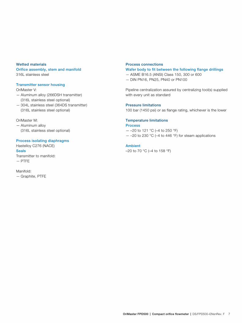
Wetted materialsOrifice assembly, stem and manifold316L stainless steel
Transmitter sensor housingOriMaster V:— Aluminum alloy (266DSH transmitter)
(316L stainless steel optional)— 304L stainless steel (364DS transmitter)
(316L stainless steel optional)
OriMaster M:— Aluminum alloy
(316L stainless steel optional)
Process isolating diaphragmsHastelloy C276 (NACE)SealsTransmitter to manifold:— PTFE
Manifold:— Graphite, PTFE
Process connectionsWafer body to fit between the following flange drillings— ASME B16.5 (ANSI) Class 150, 300 or 600— DIN PN16, PN25, PN40 or PN100
Pipeline centralization assured by centralizing tool(s) supplied with every unit as standard
Pressure limitations100 bar (1450 psi) or as flange rating, whichever is the lower
Temperature limitationsProcess— –20 to 121 °C (–4 to 250 °F)— –20 to 230 °C (–4 to 446 °F) for steam applications
Ambient–20 to 70 °C (–4 to 158 °F)
OriMaster FPD500Compact orifice flowmeter
8 DS/FPD500–ENsnRev. F | OriMaster FPD500 | Compact orifice flowmeter
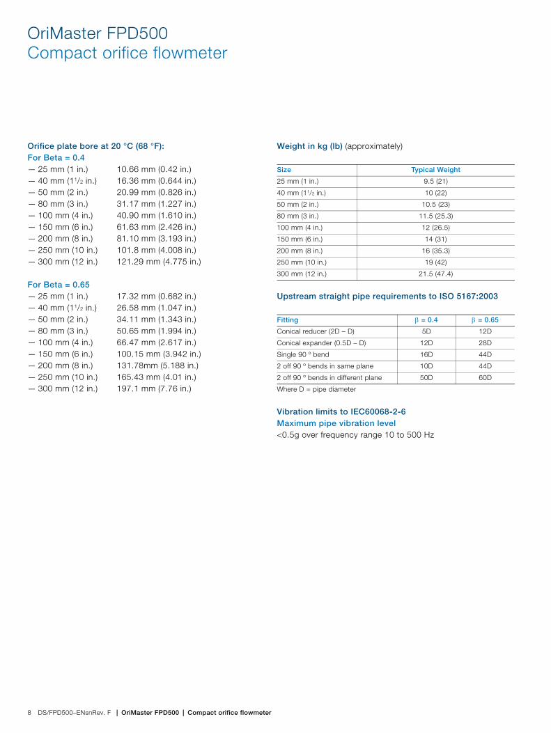
Orifice plate bore at 20 °C (68 °F):For Beta = 0.4— 25 mm (1 in.) 10.66 mm (0.42 in.)— 40 mm (11/2 in.) 16.36 mm (0.644 in.)— 50 mm (2 in.) 20.99 mm (0.826 in.)— 80 mm (3 in.) 31.17 mm (1.227 in.)— 100 mm (4 in.) 40.90 mm (1.610 in.)— 150 mm (6 in.) 61.63 mm (2.426 in.)— 200 mm (8 in.) 81.10 mm (3.193 in.)— 250 mm (10 in.) 101.8 mm (4.008 in.)— 300 mm (12 in.) 121.29 mm (4.775 in.)
For Beta = 0.65— 25 mm (1 in.) 17.32 mm (0.682 in.)— 40 mm (11/2 in.) 26.58 mm (1.047 in.)— 50 mm (2 in.) 34.11 mm (1.343 in.)— 80 mm (3 in.) 50.65 mm (1.994 in.)— 100 mm (4 in.) 66.47 mm (2.617 in.)— 150 mm (6 in.) 100.15 mm (3.942 in.)— 200 mm (8 in.) 131.78mm (5.188 in.)— 250 mm (10 in.) 165.43 mm (4.01 in.)— 300 mm (12 in.) 197.1 mm (7.76 in.)
Weight in kg (lb) (approximately)
Upstream straight pipe requirements to ISO 5167:2003
Vibration limits to IEC60068-2-6Maximum pipe vibration level<0.5g over frequency range 10 to 500 Hz
Size Typical Weight
25 mm (1 in.) 9.5 (21)
40 mm (11/2 in.) 10 (22)
50 mm (2 in.) 10.5 (23)
80 mm (3 in.) 11.5 (25.3)
100 mm (4 in.) 12 (26.5)
150 mm (6 in.) 14 (31)
200 mm (8 in.) 16 (35.3)
250 mm (10 in.) 19 (42)
300 mm (12 in.) 21.5 (47.4)
Fitting = 0.4 = 0.65
Conical reducer (2D – D) 5D 12D
Conical expander (0.5D – D) 12D 28D
Single 90 º bend 16D 44D
2 off 90 º bends in same plane 10D 44D
2 off 90 º bends in different plane 50D 60D
Where D = pipe diameter
OriMaster FPD500 | Compact orifice flowmeter | DS/FPD500–ENsnRev. F 9
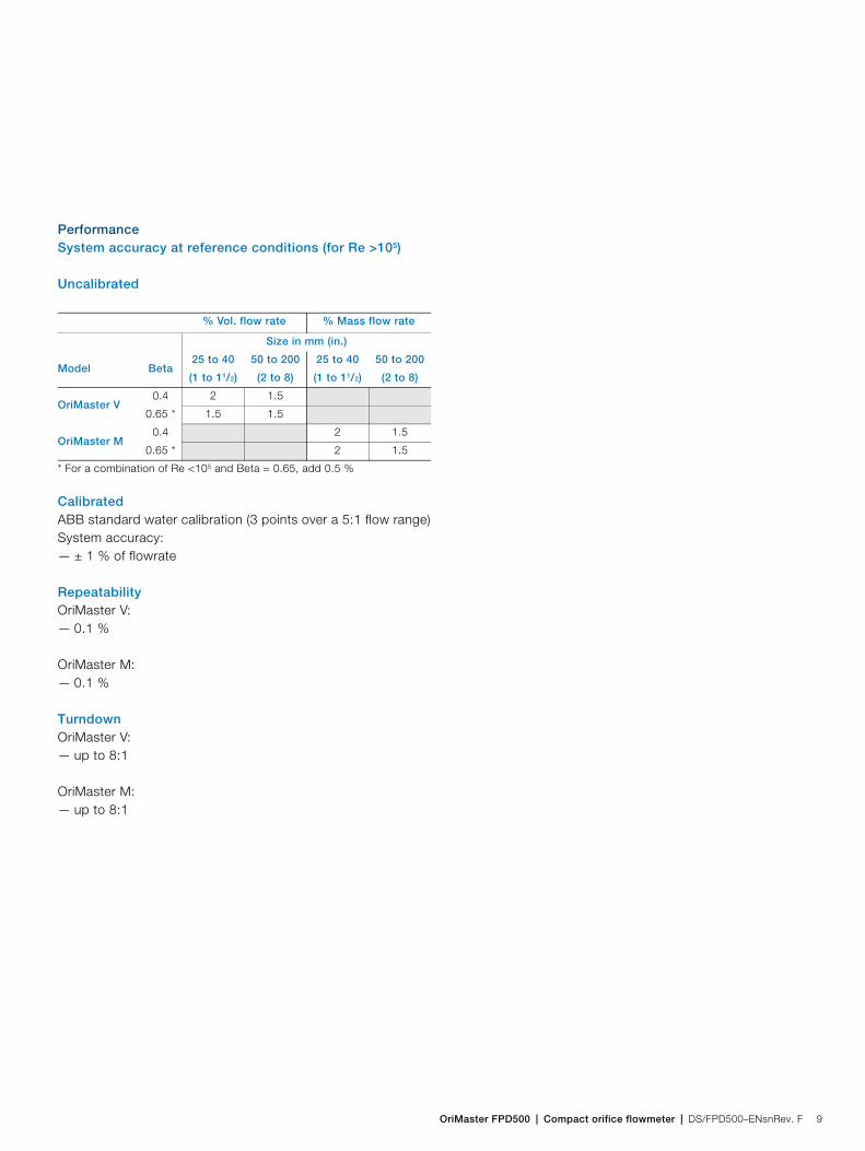
PerformanceSystem accuracy at reference conditions (for Re >105)
Uncalibrated
CalibratedABB standard water calibration (3 points over a 5:1 flow range)System accuracy:— ± 1 % of flowrate
RepeatabilityOriMaster V:— 0.1 %
OriMaster M:— 0.1 %
TurndownOriMaster V:— up to 8:1
OriMaster M:— up to 8:1
% Vol. flow rate % Mass flow rate
Size in mm (in.)
Model Beta25 to 40
(1 to 11/2)
50 to 200
(2 to 8)
25 to 40
(1 to 11/2)
50 to 200
(2 to 8)
OriMaster V0.4 2 1.5
0.65 * 1.5 1.5
OriMaster M0.4 2 1.5
0.65 * 2 1.5
* For a combination of Re <105 and Beta = 0.65, add 0.5 %
OriMaster FPD500Compact orifice flowmeter
10 DS/FPD500–ENsnRev. F | OriMaster FPD500 | Compact orifice flowmeter
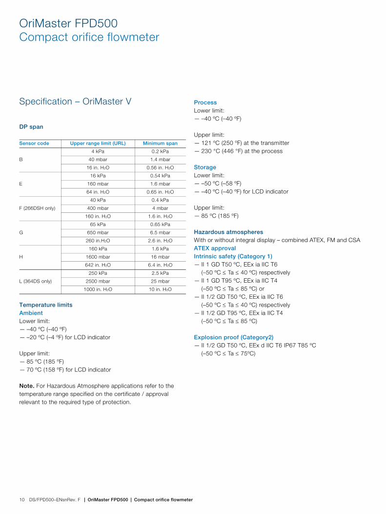
Specification – OriMaster V
DP span
Temperature limitsAmbientLower limit:— –40 ºC (–40 ºF)— –20 ºC (–4 ºF) for LCD indicator
Upper limit:— 85 ºC (185 ºF)— 70 ºC (158 ºF) for LCD indicator
Note. For Hazardous Atmosphere applications refer to the temperature range specified on the certificate / approval relevant to the required type of protection.
ProcessLower limit:— –40 ºC (–40 ºF)
Upper limit:— 121 ºC (250 ºF) at the transmitter— 230 °C (446 °F) at the process
StorageLower limit:— –50 ºC (–58 ºF)— –40 ºC (–40 ºF) for LCD indicator
Upper limit:— 85 ºC (185 ºF)
Hazardous atmospheresWith or without integral display – combined ATEX, FM and CSAATEX approvalIntrinsic safety (Category 1)— II 1 GD T50 ºC, EEx ia IIC T6
(–50 ºC Ta 40 ºC) respectively— II 1 GD T95 ºC, EEx ia IIC T4
(–50 ºC Ta 85 ºC) or— II 1/2 GD T50 ºC, EEx ia IIC T6
(–50 ºC Ta 40 ºC) respectively— II 1/2 GD T95 ºC, EEx ia IIC T4
(–50 ºC Ta 85 ºC)
Explosion proof (Category2)— II 1/2 GD T50 ºC, EEx d IIC T6 IP67 T85 ºC
(–50 ºC Ta 75ºC)
Sensor code Upper range limit (URL) Minimum span
B
4 kPa 0.2 kPa
40 mbar 1.4 mbar
16 in. H2O 0.56 in. H2O
E
16 kPa 0.54 kPa
160 mbar 1.6 mbar
64 in. H2O 0.65 in. H2O
F (266DSH only)
40 kPa 0.4 kPa
400 mbar 4 mbar
160 in. H2O 1.6 in. H2O
G
65 kPa 0.65 kPa
650 mbar 6.5 mbar
260 in.H2O 2.6 in. H2O
H
160 kPa 1.6 kPa
1600 mbar 16 mbar
642 in. H2O 6.4 in. H2O
L (364DS only)
250 kPa 2.5 kPa
2500 mbar 25 mbar
1000 in. H2O 10 in. H2O

OriMaster FPD500 | Compact orifice flowmeter | DS/FPD500–ENsnRev. F 11
Canadian Standards Association (CSA) and Factory Mutual (FM)Explosion proof:— Class I, Div. 1, Groups A, B, C, D
Dust ignition proof:— Class II, Div. 1, Groups E, F, G
Suitable for:— Class II, Div. 2, Groups F, G; Class III, Div. 1, 2
Non-incendive:— Class I, Div. 2, Groups A, B, C, D
Intrinsically safe:— Class I, II, III, Div. 1, Groups A, B, C, D, E, F, G AEx ia IIC
T6/T4, Zone 0 (FM)
OriMaster FPD500Compact orifice flowmeter
12 DS/FPD500–ENsnRev. F | OriMaster FPD500 | Compact orifice flowmeter
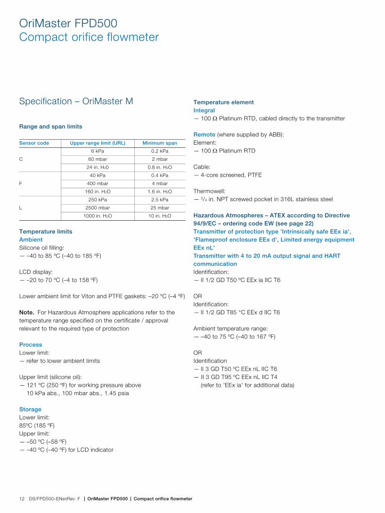
Specification – OriMaster M
Range and span limits
Temperature limitsAmbientSilicone oil filling:— –40 to 85 ºC (–40 to 185 ºF)
LCD display:— –20 to 70 ºC (–4 to 158 ºF)
Lower ambient limit for Viton and PTFE gaskets: –20 ºC (–4 ºF)
Note. For Hazardous Atmosphere applications refer to the temperature range specified on the certificate / approval relevant to the required type of protection
ProcessLower limit:— refer to lower ambient limits
Upper limit (silicone oil):— 121 ºC (250 ºF) for working pressure above
10 kPa abs., 100 mbar abs., 1.45 psia
StorageLower limit:85ºC (185 ºF)Upper limit:— –50 ºC (–58 ºF)— –40 ºC (–40 ºF) for LCD indicator
Temperature elementIntegral— 100 Platinum RTD, cabled directly to the transmitter
Remote (where supplied by ABB):Element:— 100 Platinum RTD
Cable:— 4-core screened, PTFE
Thermowell:— 3/4 in. NPT screwed pocket in 316L stainless steel
Hazardous Atmospheres – ATEX according to Directive 94/9/EC – ordering code EW (see page 22)Transmitter of protection type 'Intrinsically safe EEx ia', 'Flameproof enclosure EEx d', Limited energy equipment EEx nL'Transmitter with 4 to 20 mA output signal and HART communicationIdentification:— II 1/2 GD T50 ºC EEx ia IIC T6
ORIdentification:— II 1/2 GD T85 °C EEx d IIC T6
Ambient temperature range:— –40 to 75 ºC (–40 to 167 ºF)
ORIdentification— II 3 GD T50 ºC EEx nL IIC T6— II 3 GD T95 ºC EEx nL IIC T4
(refer to 'EEx ia' for additional data)
Sensor code Upper range limit (URL) Minimum span
C
6 kPa 0.2 kPa
60 mbar 2 mbar
24 in. H20 0.8 in. H2O
F
40 kPa 0.4 kPa
400 mbar 4 mbar
160 in. H2O 1.6 in. H2O
L
250 kPa 2.5 kPa
2500 mbar 25 mbar
1000 in. H2O 10 in. H2O
OriMaster FPD500 | Compact orifice flowmeter | DS/FPD500–ENsnRev. F 13
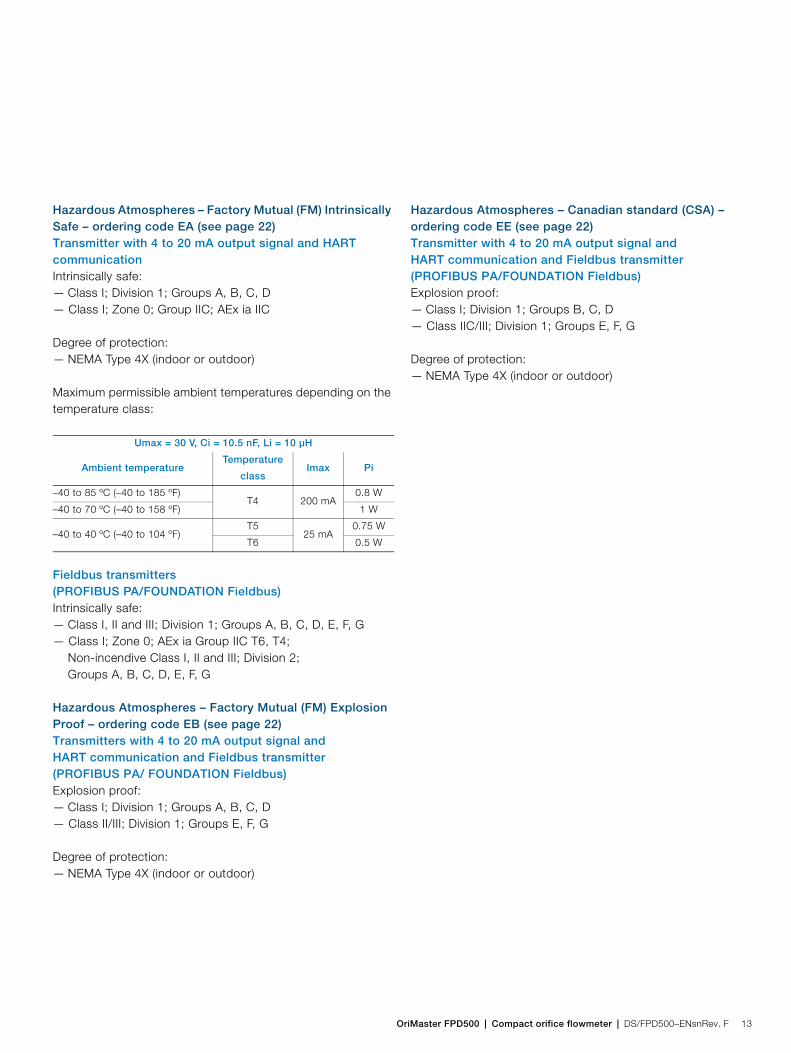
Hazardous Atmospheres – Factory Mutual (FM) Intrinsically Safe – ordering code EA (see page 22)Transmitter with 4 to 20 mA output signal and HART communicationIntrinsically safe:— Class I; Division 1; Groups A, B, C, D— Class I; Zone 0; Group IIC; AEx ia IIC
Degree of protection:— NEMA Type 4X (indoor or outdoor)
Maximum permissible ambient temperatures depending on the temperature class:
Fieldbus transmitters (PROFIBUS PA/FOUNDATION Fieldbus)Intrinsically safe:— Class I, II and III; Division 1; Groups A, B, C, D, E, F, G— Class I; Zone 0; AEx ia Group IIC T6, T4;
Non-incendive Class I, II and III; Division 2;Groups A, B, C, D, E, F, G
Hazardous Atmospheres – Factory Mutual (FM) Explosion Proof – ordering code EB (see page 22)Transmitters with 4 to 20 mA output signal and HART communication and Fieldbus transmitter (PROFIBUS PA/ FOUNDATION Fieldbus)Explosion proof:— Class I; Division 1; Groups A, B, C, D — Class II/III; Division 1; Groups E, F, G
Degree of protection:— NEMA Type 4X (indoor or outdoor)
Hazardous Atmospheres – Canadian standard (CSA) – ordering code EE (see page 22)Transmitter with 4 to 20 mA output signal and HART communication and Fieldbus transmitter (PROFIBUS PA/FOUNDATION Fieldbus)Explosion proof:— Class I; Division 1; Groups B, C, D — Class IIC/III; Division 1; Groups E, F, G
Degree of protection:— NEMA Type 4X (indoor or outdoor)
Umax = 30 V, Ci = 10.5 nF, Li = 10 µH
Ambient temperatureTemperature
classImax Pi
–40 to 85 ºC (–40 to 185 ºF)T4 200 mA
0.8 W
–40 to 70 ºC (–40 to 158 ºF) 1 W
–40 to 40 ºC (–40 to 104 ºF)T5
25 mA0.75 W
T6 0.5 W
OriMaster FPD500Compact orifice flowmeter
14 DS/FPD500–ENsnRev. F | OriMaster FPD500 | Compact orifice flowmeter
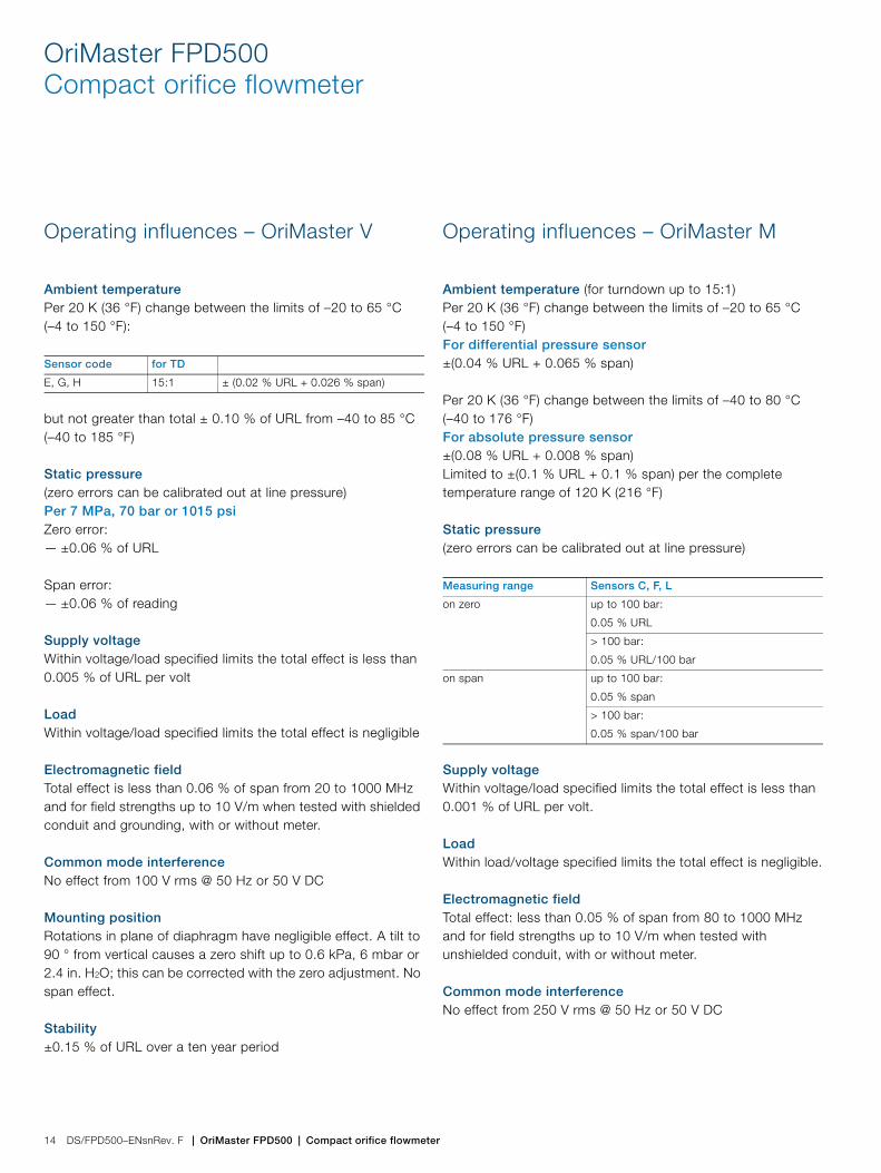
Operating influences – OriMaster V
Ambient temperaturePer 20 K (36 °F) change between the limits of –20 to 65 °C (–4 to 150 °F):
but not greater than total ± 0.10 % of URL from –40 to 85 °C (–40 to 185 °F)
Static pressure (zero errors can be calibrated out at line pressure)Per 7 MPa, 70 bar or 1015 psiZero error:— ±0.06 % of URL
Span error:— ±0.06 % of reading
Supply voltageWithin voltage/load specified limits the total effect is less than 0.005 % of URL per volt
LoadWithin voltage/load specified limits the total effect is negligible
Electromagnetic fieldTotal effect is less than 0.06 % of span from 20 to 1000 MHz and for field strengths up to 10 V/m when tested with shielded conduit and grounding, with or without meter.
Common mode interferenceNo effect from 100 V rms @ 50 Hz or 50 V DC
Mounting positionRotations in plane of diaphragm have negligible effect. A tilt to 90 ° from vertical causes a zero shift up to 0.6 kPa, 6 mbar or 2.4 in. H2O; this can be corrected with the zero adjustment. No span effect.
Stability±0.15 % of URL over a ten year period
Operating influences – OriMaster M
Ambient temperature (for turndown up to 15:1)Per 20 K (36 °F) change between the limits of –20 to 65 °C (–4 to 150 °F)For differential pressure sensor±(0.04 % URL + 0.065 % span)
Per 20 K (36 °F) change between the limits of –40 to 80 °C (–40 to 176 °F)For absolute pressure sensor±(0.08 % URL + 0.008 % span)Limited to ±(0.1 % URL + 0.1 % span) per the complete temperature range of 120 K (216 °F)
Static pressure (zero errors can be calibrated out at line pressure)
Supply voltageWithin voltage/load specified limits the total effect is less than 0.001 % of URL per volt.
LoadWithin load/voltage specified limits the total effect is negligible.
Electromagnetic fieldTotal effect: less than 0.05 % of span from 80 to 1000 MHz and for field strengths up to 10 V/m when tested with unshielded conduit, with or without meter.
Common mode interferenceNo effect from 250 V rms @ 50 Hz or 50 V DC
Sensor code for TD
E, G, H 15:1 ± (0.02 % URL + 0.026 % span)
Measuring range Sensors C, F, L
on zero up to 100 bar:
0.05 % URL
> 100 bar:
0.05 % URL/100 bar
on span up to 100 bar:
0.05 % span
> 100 bar:
0.05 % span/100 bar

OriMaster FPD500 | Compact orifice flowmeter | DS/FPD500–ENsnRev. F 15
Mounting positionRotations in plane of diaphragm have negligible effect. A tilt from vertical causes a zero shift of sin x 0.35 kPa (3.5 mbar, 1.4 in. H2O) of URL; this can be corrected with the zero adjustment. No span effect.
Stability±0.15 % of URL over a sixty-month period
OriMaster FPD500Compact orifice flowmeter
16 DS/FPD500–ENsnRev. F | OriMaster FPD500 | Compact orifice flowmeter
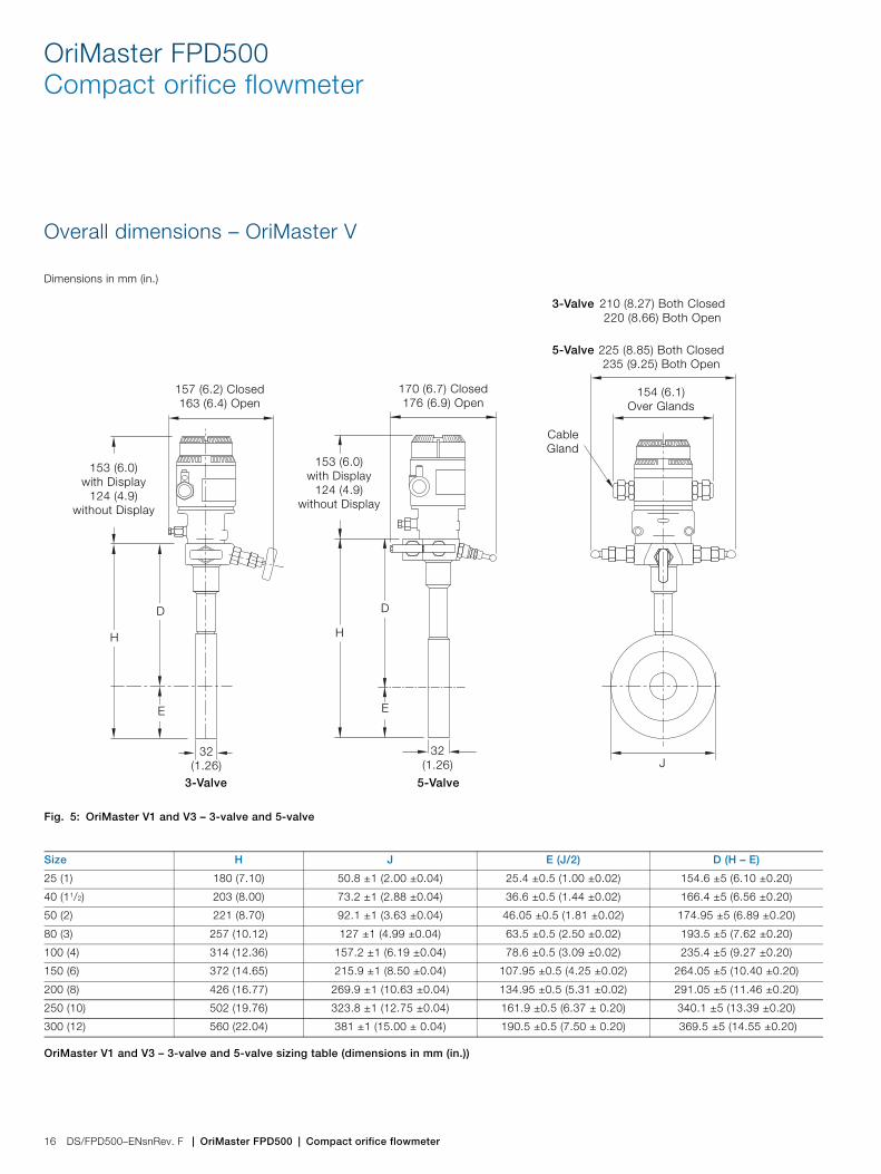
Overall dimensions – OriMaster V
Dimensions in mm (in.)
Fig. 5: OriMaster V1 and V3 – 3-valve and 5-valve
Size H J E (J/2) D (H – E)
25 (1) 180 (7.10) 50.8 ±1 (2.00 ±0.04) 25.4 ±0.5 (1.00 ±0.02) 154.6 ±5 (6.10 ±0.20)
40 (11/2) 203 (8.00) 73.2 ±1 (2.88 ±0.04) 36.6 ±0.5 (1.44 ±0.02) 166.4 ±5 (6.56 ±0.20)
50 (2) 221 (8.70) 92.1 ±1 (3.63 ±0.04) 46.05 ±0.5 (1.81 ±0.02) 174.95 ±5 (6.89 ±0.20)
80 (3) 257 (10.12) 127 ±1 (4.99 ±0.04) 63.5 ±0.5 (2.50 ±0.02) 193.5 ±5 (7.62 ±0.20)
100 (4) 314 (12.36) 157.2 ±1 (6.19 ±0.04) 78.6 ±0.5 (3.09 ±0.02) 235.4 ±5 (9.27 ±0.20)
150 (6) 372 (14.65) 215.9 ±1 (8.50 ±0.04) 107.95 ±0.5 (4.25 ±0.02) 264.05 ±5 (10.40 ±0.20)
200 (8) 426 (16.77) 269.9 ±1 (10.63 ±0.04) 134.95 ±0.5 (5.31 ±0.02) 291.05 ±5 (11.46 ±0.20)
250 (10) 502 (19.76) 323.8 ±1 (12.75 ±0.04) 161.9 ±0.5 (6.37 ± 0.20) 340.1 ±5 (13.39 ±0.20)
300 (12) 560 (22.04) 381 ±1 (15.00 ± 0.04) 190.5 ±0.5 (7.50 ± 0.20) 369.5 ±5 (14.55 ±0.20)
OriMaster V1 and V3 – 3-valve and 5-valve sizing table (dimensions in mm (in.))
CableGland
154 (6.1) Over Glands
157 (6.2) Closed163 (6.4) Open
153 (6.0) with Display
124 (4.9) without Display
H
E
J
D
32(1.26)
3-Valve 5-Valve
210 (8.27) Both Closed220 (8.66) Both Open
225 (8.85) Both Closed235 (9.25) Both Open
3-Valve
5-Valve
170 (6.7) Closed176 (6.9) Open
153 (6.0) with Display
124 (4.9) without Display
H
E
D
32(1.26)
OriMaster FPD500 | Compact orifice flowmeter | DS/FPD500–ENsnRev. F 17
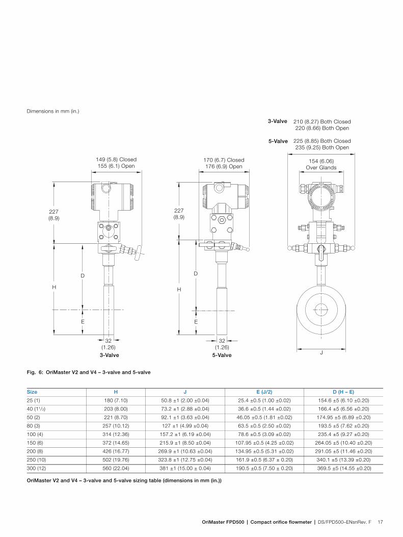
Dimensions in mm (in.)
Fig. 6: OriMaster V2 and V4 – 3-valve and 5-valve
Size H J E (J/2) D (H – E)
25 (1) 180 (7.10) 50.8 ±1 (2.00 ±0.04) 25.4 ±0.5 (1.00 ±0.02) 154.6 ±5 (6.10 ±0.20)
40 (11/2) 203 (8.00) 73.2 ±1 (2.88 ±0.04) 36.6 ±0.5 (1.44 ±0.02) 166.4 ±5 (6.56 ±0.20)
50 (2) 221 (8.70) 92.1 ±1 (3.63 ±0.04) 46.05 ±0.5 (1.81 ±0.02) 174.95 ±5 (6.89 ±0.20)
80 (3) 257 (10.12) 127 ±1 (4.99 ±0.04) 63.5 ±0.5 (2.50 ±0.02) 193.5 ±5 (7.62 ±0.20)
100 (4) 314 (12.36) 157.2 ±1 (6.19 ±0.04) 78.6 ±0.5 (3.09 ±0.02) 235.4 ±5 (9.27 ±0.20)
150 (6) 372 (14.65) 215.9 ±1 (8.50 ±0.04) 107.95 ±0.5 (4.25 ±0.02) 264.05 ±5 (10.40 ±0.20)
200 (8) 426 (16.77) 269.9 ±1 (10.63 ±0.04) 134.95 ±0.5 (5.31 ±0.02) 291.05 ±5 (11.46 ±0.20)
250 (10) 502 (19.76) 323.8 ±1 (12.75 ±0.04) 161.9 ±0.5 (6.37 ± 0.20) 340.1 ±5 (13.39 ±0.20)
300 (12) 560 (22.04) 381 ±1 (15.00 ± 0.04) 190.5 ±0.5 (7.50 ± 0.20) 369.5 ±5 (14.55 ±0.20)
OriMaster V2 and V4 – 3-valve and 5-valve sizing table (dimensions in mm (in.))
3-Valve 5-Valve
3-Valve
5-Valve
154 (6.06) Over Glands
210 (8.27) Both Closed220 (8.66) Both Open
225 (8.85) Both Closed235 (9.25) Both Open
H
E
D
149 (5.8) Closed155 (6.1) Open
227(8.9)
J
32(1.26)
170 (6.7) Closed176 (6.9) Open
32(1.26)
227(8.9)
H
E
D
OriMaster FPD500Compact orifice flowmeter
18 DS/FPD500–ENsnRev. F | OriMaster FPD500 | Compact orifice flowmeter
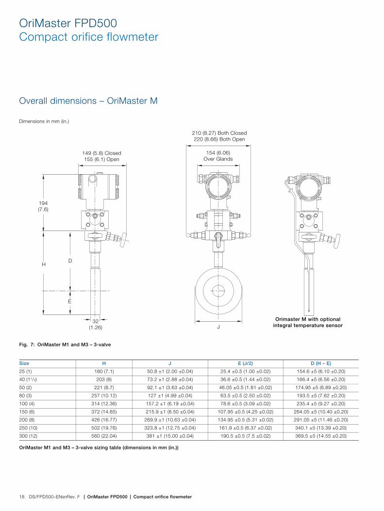
Overall dimensions – OriMaster M
Dimensions in mm (in.)
Fig. 7: OriMaster M1 and M3 – 3-valve
Size H J E (J/2) D (H – E)
25 (1) 180 (7.1) 50.8 ±1 (2.00 ±0.04) 25.4 ±0.5 (1.00 ±0.02) 154.6 ±5 (6.10 ±0.20)
40 (11/2) 203 (8) 73.2 ±1 (2.88 ±0.04) 36.6 ±0.5 (1.44 ±0.02) 166.4 ±5 (6.56 ±0.20)
50 (2) 221 (8.7) 92.1 ±1 (3.63 ±0.04) 46.05 ±0.5 (1.81 ±0.02) 174.95 ±5 (6.89 ±0.20)
80 (3) 257 (10.12) 127 ±1 (4.99 ±0.04) 63.5 ±0.5 (2.50 ±0.02) 193.5 ±5 (7.62 ±0.20)
100 (4) 314 (12.36) 157.2 ±1 (6.19 ±0.04) 78.6 ±0.5 (3.09 ±0.02) 235.4 ±5 (9.27 ±0.20)
150 (6) 372 (14.65) 215.9 ±1 (8.50 ±0.04) 107.95 ±0.5 (4.25 ±0.02) 264.05 ±5 (10.40 ±0.20)
200 (8) 426 (16.77) 269.9 ±1 (10.63 ±0.04) 134.95 ±0.5 (5.31 ±0.02) 291.05 ±5 (11.46 ±0.20)
250 (10) 502 (19.76) 323.8 ±1 (12.75 ±0.04) 161.9 ±0.5 (6.37 ±0.02) 340.1 ±5 (13.39 ±0.20)
300 (12) 560 (22.04) 381 ±1 (15.00 ±0.04) 190.5 ±0.5 (7.5 ±0.02) 369.5 ±5 (14.55 ±0.20)
OriMaster M1 and M3 – 3-valve sizing table (dimensions in mm (in.))
154 (6.06) Over Glands
210 (8.27) Both Closed220 (8.66) Both Open
149 (5.8) Closed155 (6.1) Open
H
E
J
D
194(7.6)
Orimaster M with optional integral temperature sensor
32 (1.26)
OriMaster FPD500 | Compact orifice flowmeter | DS/FPD500–ENsnRev. F 19
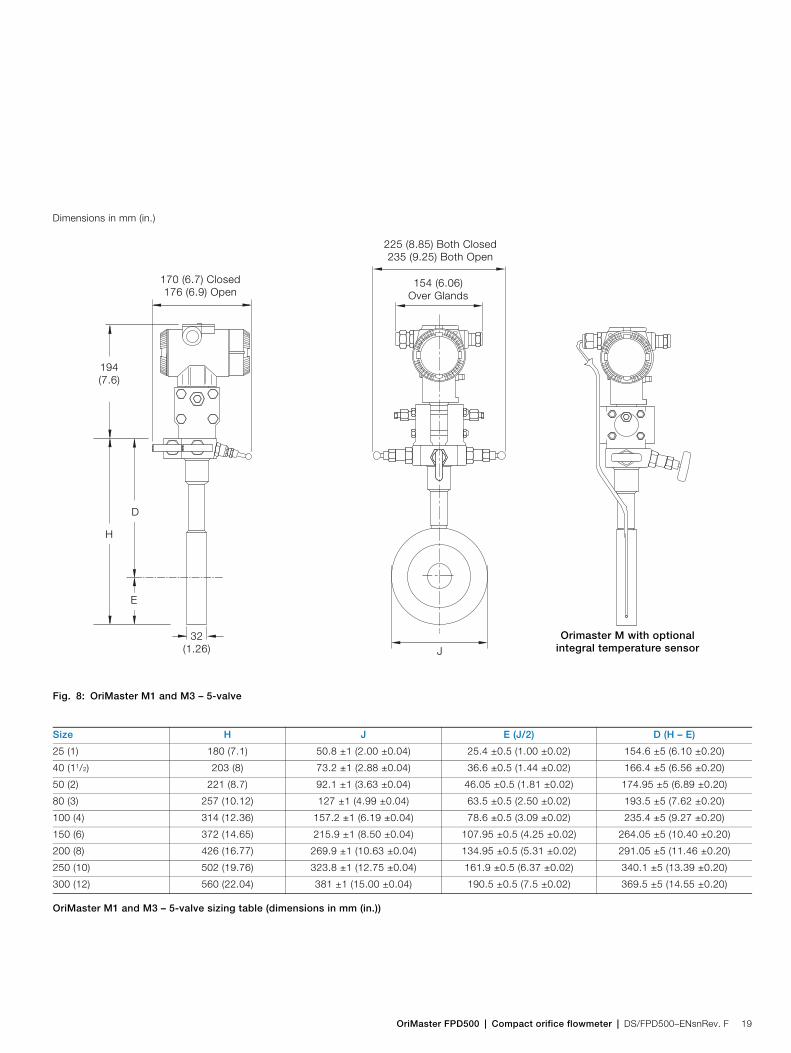
Dimensions in mm (in.)
Fig. 8: OriMaster M1 and M3 – 5-valve
Size H J E (J/2) D (H – E)
25 (1) 180 (7.1) 50.8 ±1 (2.00 ±0.04) 25.4 ±0.5 (1.00 ±0.02) 154.6 ±5 (6.10 ±0.20)
40 (11/2) 203 (8) 73.2 ±1 (2.88 ±0.04) 36.6 ±0.5 (1.44 ±0.02) 166.4 ±5 (6.56 ±0.20)
50 (2) 221 (8.7) 92.1 ±1 (3.63 ±0.04) 46.05 ±0.5 (1.81 ±0.02) 174.95 ±5 (6.89 ±0.20)
80 (3) 257 (10.12) 127 ±1 (4.99 ±0.04) 63.5 ±0.5 (2.50 ±0.02) 193.5 ±5 (7.62 ±0.20)
100 (4) 314 (12.36) 157.2 ±1 (6.19 ±0.04) 78.6 ±0.5 (3.09 ±0.02) 235.4 ±5 (9.27 ±0.20)
150 (6) 372 (14.65) 215.9 ±1 (8.50 ±0.04) 107.95 ±0.5 (4.25 ±0.02) 264.05 ±5 (10.40 ±0.20)
200 (8) 426 (16.77) 269.9 ±1 (10.63 ±0.04) 134.95 ±0.5 (5.31 ±0.02) 291.05 ±5 (11.46 ±0.20)
250 (10) 502 (19.76) 323.8 ±1 (12.75 ±0.04) 161.9 ±0.5 (6.37 ±0.02) 340.1 ±5 (13.39 ±0.20)
300 (12) 560 (22.04) 381 ±1 (15.00 ±0.04) 190.5 ±0.5 (7.5 ±0.02) 369.5 ±5 (14.55 ±0.20)
OriMaster M1 and M3 – 5-valve sizing table (dimensions in mm (in.))
154 (6.06) Over Glands
225 (8.85) Both Closed235 (9.25) Both Open
170 (6.7) Closed176 (6.9) Open
H
E
J
D
194(7.6)
Orimaster M with optional integral temperature sensor
32 (1.26)
OriMaster FPD500Compact orifice flowmeter
20 DS/FPD500–ENsnRev. F | OriMaster FPD500 | Compact orifice flowmeter
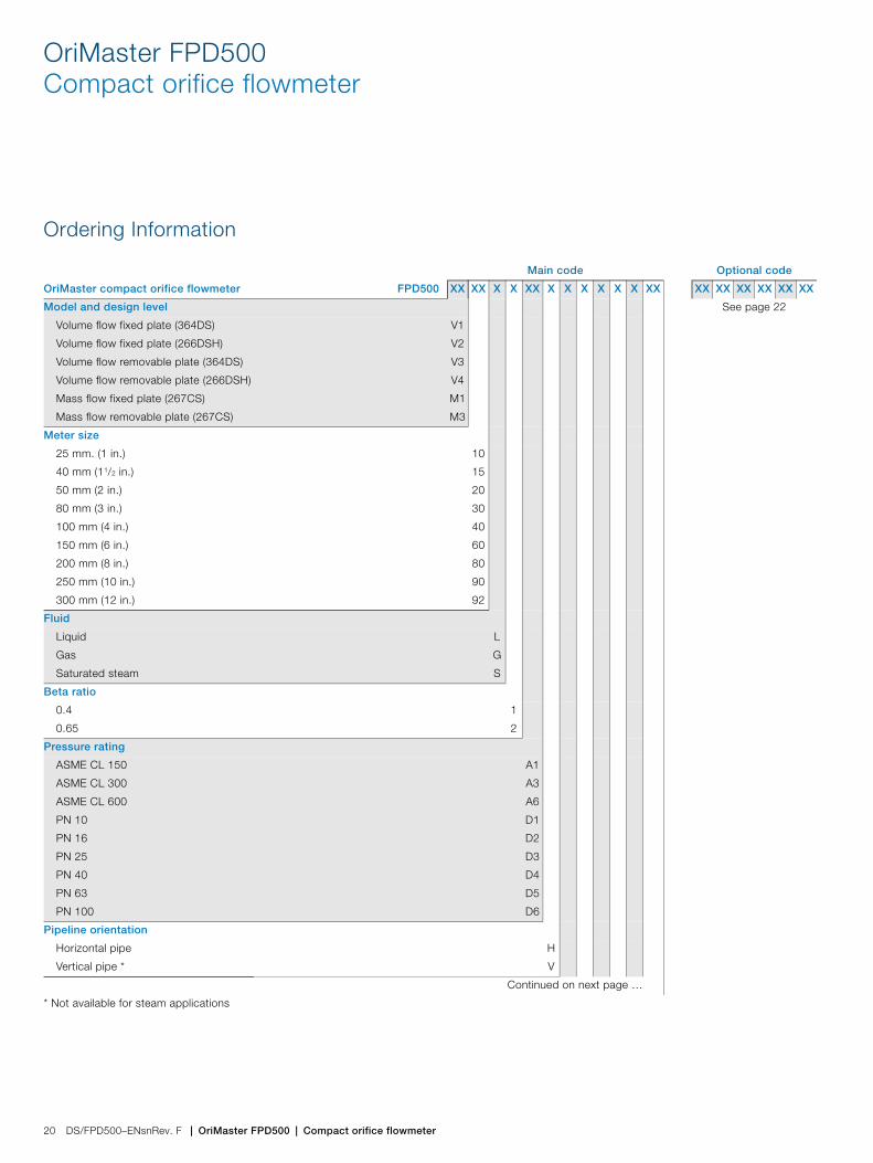
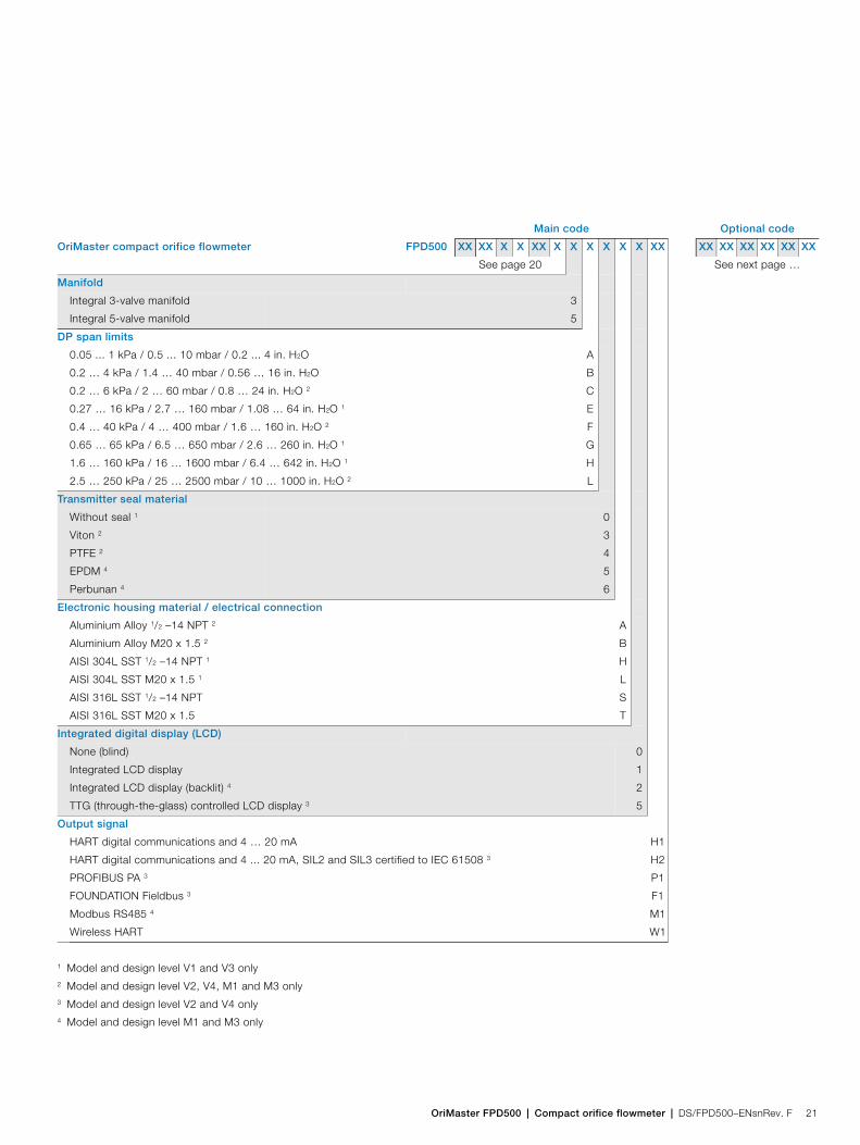
Ordering Information
Main code Optional code
OriMaster compact orifice flowmeter FPD500 XX XX X X XX X X X X X X XX XX XX XX XX XX XX
Model and design level See page 22
Volume flow fixed plate (364DS)
Volume flow fixed plate (266DSH)
Volume flow removable plate (364DS)
Volume flow removable plate (266DSH)
Mass flow fixed plate (267CS)
Mass flow removable plate (267CS)
V1
V2
V3
V4
M1
M3
Meter size
25 mm. (1 in.)
40 mm (11/2 in.)
50 mm (2 in.)
80 mm (3 in.)
100 mm (4 in.)
150 mm (6 in.)
200 mm (8 in.)
250 mm (10 in.)
300 mm (12 in.)
10
15
20
30
40
60
80
90
92
Fluid
Liquid
Gas
Saturated steam
L
G
S
Beta ratio
0.4
0.65
1
2
Pressure rating
ASME CL 150
ASME CL 300
ASME CL 600
PN 10
PN 16
PN 25
PN 40
PN 63
PN 100
A1
A3
A6
D1
D2
D3
D4
D5
D6
Pipeline orientation
Horizontal pipe
Vertical pipe *
H
V
Continued on next page …
* Not available for steam applications
OriMaster FPD500 | Compact orifice flowmeter | DS/FPD500–ENsnRev. F 21
See page 20 See next page …
Manifold
Integral 3-valve manifold
Integral 5-valve manifold
3
5
DP span limits
0.05 ... 1 kPa / 0.5 ... 10 mbar / 0.2 ... 4 in. H2O
0.2 … 4 kPa / 1.4 … 40 mbar / 0.56 … 16 in. H2O
0.2 … 6 kPa / 2 … 60 mbar / 0.8 … 24 in. H2O 2
0.27 … 16 kPa / 2.7 … 160 mbar / 1.08 … 64 in. H2O 1
0.4 … 40 kPa / 4 … 400 mbar / 1.6 … 160 in. H2O 2
0.65 … 65 kPa / 6.5 … 650 mbar / 2.6 … 260 in. H2O 1
1.6 … 160 kPa / 16 … 1600 mbar / 6.4 … 642 in. H2O 1
2.5 … 250 kPa / 25 … 2500 mbar / 10 … 1000 in. H2O 2
A
B
C
E
F
G
H
L
Transmitter seal material
Without seal 1
Viton 2
PTFE 2
EPDM 4
Perbunan 4
0
3
4
5
6
Electronic housing material / electrical connection
Aluminium Alloy 1/2 –14 NPT 2
Aluminium Alloy M20 x 1.5 2
AISI 304L SST 1/2 –14 NPT 1
AISI 304L SST M20 x 1.5 1
AISI 316L SST 1/2 –14 NPT
AISI 316L SST M20 x 1.5
A
B
H
L
S
T
Integrated digital display (LCD)
None (blind)
Integrated LCD display
Integrated LCD display (backlit) 4
TTG (through-the-glass) controlled LCD display 3
0
1
2
5
Output signal
HART digital communications and 4 … 20 mA
HART digital communications and 4 ... 20 mA, SIL2 and SIL3 certified to IEC 61508 3
PROFIBUS PA 3
FOUNDATION Fieldbus 3
Modbus RS485 4
Wireless HART
H1
H2
P1
F1
M1
W1
1 Model and design level V1 and V3 only2 Model and design level V2, V4, M1 and M3 only3 Model and design level V2 and V4 only4 Model and design level M1 and M3 only
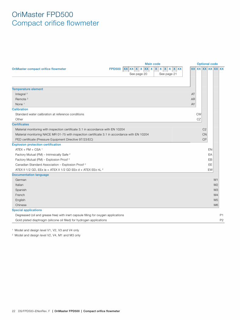
Main code Optional code
OriMaster compact orifice flowmeter FPD500 XX XX X X XX X X X X X X XX XX XX XX XX XX XX
OriMaster FPD500Compact orifice flowmeter
22 DS/FPD500–ENsnRev. F | OriMaster FPD500 | Compact orifice flowmeter
See page 20 See page 21
Temperature element
Integral 2
Remote 2
None 1
AT
AR
AY
Calibration
Standard water calibration at reference conditions
Other
CW
CZ
Certificates
Material monitoring with inspection certificate 3.1 in accordance with EN 10204
Material monitoring NACE MR 01-75 with inspection certificate 3.1 in accordance with EN 10204
PED certificate (Pressure Equipment Directive 97/23/EC)
C2
CN
CP
Explosion protection certification
ATEX + FM + CSA 1
Factory Mutual (FM) – Intrinsically Safe 2
Factory Mutual (FM) – Explosion Proof 2
Canadian Standard Association – Explosion Proof 2
ATEX II 1/2 GD, EEx ia + ATEX II 1/2 GD EEx d + ATEX EEx nL 2
EN
EA
EB
EE
EW
Documentation language
German
Italian
Spanish
French
English
Chinese
M1
M2
M3
M4
M5
M6
Special applications
Degreased (oil and grease free) with inert capsule filling for oxygen applications
Gold plated diaphragm (silicone oil filled) for hydrogen applications
P1
P2
1 Model and design level V1, V2, V3 and V4 only2 Model and design level V2, V4, M1 and M3 only
Main code Optional code
OriMaster compact orifice flowmeter FPD500 XX XX X X XX X X X X X X XX XX XX XX XX XX XX

OriMaster FPD500 | Compact orifice flowmeter | DS/FPD500–ENsnRev. F 23
Acknowledgements
MODBUS is a registered trademark of the Modbus-IDA organizationPROFIBUS is a registered trademark of Profibus InternationalFOUNDATION is a trademark of the Fieldbus FoundationHART is a registered trademark of the HART Communication Foundation

Contact us
DS
/FP
D50
0–E
Nsn
Rev
. F
04.2
013ABB Limited
Process AutomationSalterbeck Trading EstateWorkington, CumbriaCA14 5DSUKTel: +44 (0)1946 830 611Fax: +44 (0)1946 832 661
ABB Inc.Process Automation125 E. County Line RoadWarminsterPA 18974USATel: +1 215 674 6000Fax: +1 215 674 7183
www.abb.com
NoteWe reserve the right to make technical changes or modify the contents of this document without prior notice. With regard to purchase orders, the agreed particulars shall prevail. ABB does not accept any responsibility whatsoever for potential errors or possible lack of information in this document.
We reserve all rights in this document and in the subject matter and illustrations contained therein. Any reproduction, disclosure to third parties or utilization of its contents – in whole or in parts – is forbidden without prior written consent of ABB.
Copyright© 2013 ABBAll rights reserved
3KXF511501R1001
Sales
Service
Software