Embed Size (px)
Citation preview
Product Data Sheet00813-0100-4809, Rev FA
Catalog 2008 - 2009 The Annubar Flowmeter Series
Rosemount Annubar® Flowmeter Series
• Industry leading integrated DP flowmeters are
created when Annubar primary elements are
packaged with Rosemount pressure
transmitters
• Improved performance with innovative
measuring techniques
• Real-time mass flow measurements available
with integral temperature sensor design
• Increased plant uptime with the
maintenance-free design
• Energy savings gained through minimal
permanent pressure loss
Rosemount
3051SFA
Flowmeter
Rosemount
3095MFA
Flowmeter
Rosemount 485
Annubar Primary
www.ro
Contents
The Annubar Flowmeter Series. . . . . . . . . . . . . . . . . . . . . . . . . . . . . . . . . . . . . . . . . . . page Flow-2
Annubar Flowmeter Series Selection Guide . . . . . . . . . . . . . . . . . . . . . . . . . . . . . . . . . page Flow-3
Rosemount 3051SFA ProBar® Flowmeter . . . . . . . . . . . . . . . . . . . . . . . . . . . . . . . . . . page Flow-4
Specifications . . . . . . . . . . . . . . . . . . . . . . . . . . . . . . . . . . . . . . . . . . . . . . . . . . page Flow-4
Product Certifications . . . . . . . . . . . . . . . . . . . . . . . . . . . . . . . . . . . . . . . . . . . page Flow-11
Dimensional Drawings . . . . . . . . . . . . . . . . . . . . . . . . . . . . . . . . . . . . . . . . . . page Flow-15
Ordering Information . . . . . . . . . . . . . . . . . . . . . . . . . . . . . . . . . . . . . . . . . . . page Flow-21
Rosemount 3095MFA Mass ProBar Flowmeter . . . . . . . . . . . . . . . . . . . . . . . . . . . . . page Flow-28
Specifications . . . . . . . . . . . . . . . . . . . . . . . . . . . . . . . . . . . . . . . . . . . . . . . . . page Flow-28
Installation Considerations. . . . . . . . . . . . . . . . . . . . . . . . . . . . . . . . . . . . . . . page Flow-32
Dimensional Drawings . . . . . . . . . . . . . . . . . . . . . . . . . . . . . . . . . . . . . . . . . . page Flow-35
Ordering Information . . . . . . . . . . . . . . . . . . . . . . . . . . . . . . . . . . . . . . . . . . . page Flow-41
Rosemount 485 Annubar Primary . . . . . . . . . . . . . . . . . . . . . . . . . . . . . . . . . . . . . . . . page Flow-46
Specifications . . . . . . . . . . . . . . . . . . . . . . . . . . . . . . . . . . . . . . . . . . . . . . . . . page Flow-46
Dimensional Drawings . . . . . . . . . . . . . . . . . . . . . . . . . . . . . . . . . . . . . . . . . . page Flow-50
Ordering Information . . . . . . . . . . . . . . . . . . . . . . . . . . . . . . . . . . . . . . . . . . . page Flow-57
semount.com
Product Data Sheet00813-0100-4809, Rev FA
Catalog 2008 - 2009The Annubar Flowmeter Series
The Annubar Flowmeter Series
Industry leading integrated DP flowmeters
By integrating pressure transmitter electronics with the Annubar
Averaging Pitot Tube (APT), Rosemount provides the highest
performing insertion DP flowmeter. This fully integrated flowmeter
eliminates the need for fittings, tubing, valves, adapters,
manifolds, and mounting brackets, thereby reducing welding and
installation time.
Improved performance with innovative measuring
techniques
The Annubar’s frontal slot design and revolutionary shape improve
the accuracy and repeatability of every flow measurement point.
Tight process control is gained by increased signal strength and
reduced signal noise.
Real-time mass flow measurements are available with
the integral temperature sensor design
The patented T-shaped sensor includes a sealed,
pressure-retaining thermowell that permits mass flow in all line
sizes with a single pipe penetration. Multivariable technology in
gas and steam applications compensates for pressure and
temperature variations, which can cause significant flow errors.
Plant uptime is increased with the maintenance-free
design
The Annubar sensor is designed to prevent wear and blockage in
the pipe. The electronics are the most stable in the industry and
allows up to 10 year calibration cycles, providing significant
maintenance savings.
Energy savings gained through minimal permanent
pressure loss
The non-constricting design of the Annubar sensor creates
minimal blockage in the pipe, which reduces permanent pressure
loss. Permanent pressure loss can be converted directly into
energy savings in the form of compressor cost for gas, electrical
cost for pumping liquids, and fuel costs for generating steam.
Advanced PlantWeb® Functionality
Rosemount Annubar flowmeters power PlantWeb
through a scalable architecture, advanced
diagnostics, and MultiVariable capabilities. This
reduces operational and maintenance expenditures
while improving throughput and utilities
management.
Rosemount DP-Flow Solutions
Annubar Flowmeter Series: Rosemount 3051SFA
ProBar®, 3095MFA Mass ProBar®, 485, and 285
The state-of-the-art, fifth generation Rosemount 485 Annubar
combined with the 3051S or 3095 MultiVariable transmitter creates
an accurate, repeatable and dependable insertion-type flowmeter.
The Rosemount 285 provides a commercial product offering for
your general purpose applications.
Compact Orifice Flowmeter Series: Rosemount
3051SFC, 3095MFC, and 405
Compact Orifice Flowmeters can be installed between existing
flanges, up to a Class 600 (PN100) rating. In tight fit applications,
a conditioning orifice plate version is available, requiring only two
diameters of straight run upstream.
Integral Orifice Flowmeter Series: Rosemount 3051SFP
ProPlate®, 3095MFP Mass ProPlate, and 1195
These integral orifice flowmeters eliminate the inaccuracies that
become more pronounced in small orifice line installations. The
completely assembled, ready to install flowmeters reduce cost and
simplify installation.
Orifice Plate Primary Element Systems: Rosemount
1495 and 1595 Orifice Plates, 1496 Flange Unions and
1497 Meter Sections
A comprehensive offering of orifice plates, flange unions and
meter sections that is easy to specify and order. The 1595
Conditioning Orifice provides superior performance in tight fit
applications.
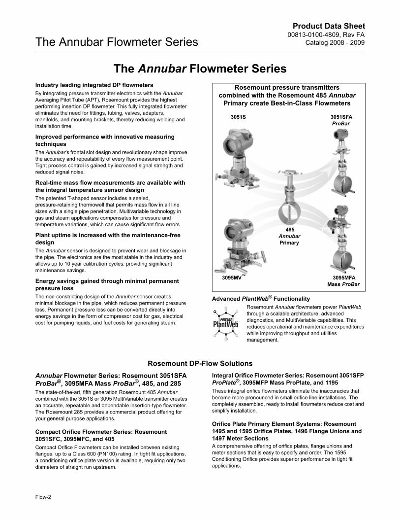
Rosemount pressure transmitters
combined with the Rosemount 485 Annubar
Primary create Best-in-Class Flowmeters
3051S
3095MV™
3051SFA
ProBar
485
Annubar
Primary
3095MFA
Mass ProBar
Flow-2
Product Data Sheet00813-0100-4809, Rev FA
Catalog 2008 - 2009 The Annubar Flowmeter Series
Annubar Flowmeter Series Selection Guide
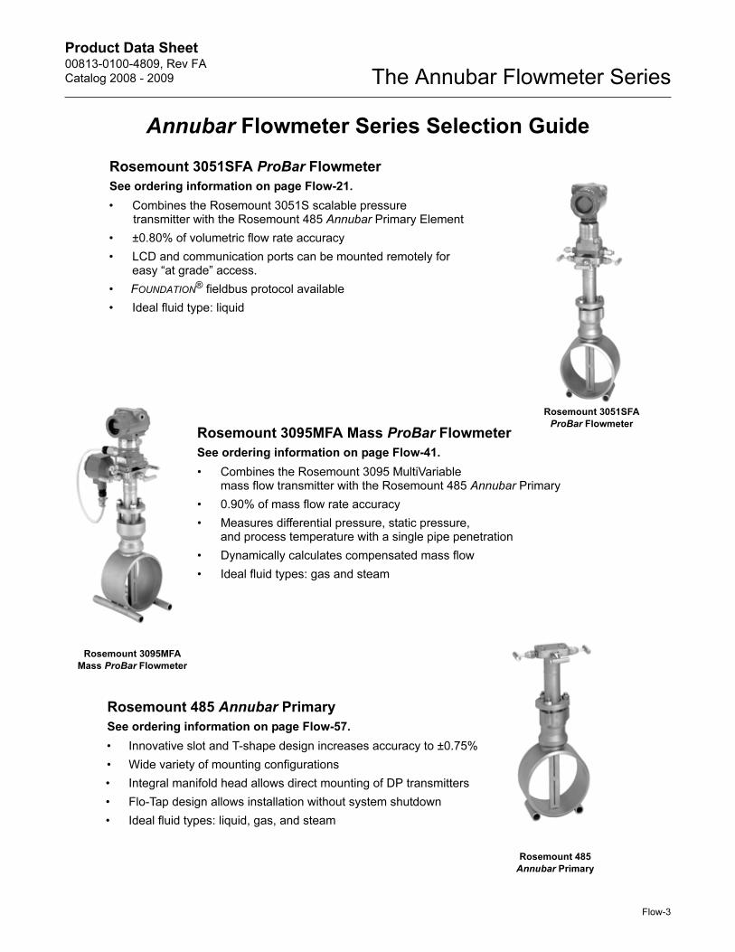
Rosemount 3051SFA ProBar Flowmeter
See ordering information on page Flow-21.
• Combines the Rosemount 3051S scalable pressure transmitter with the Rosemount 485 Annubar Primary Element
• ±0.80% of volumetric flow rate accuracy
• LCD and communication ports can be mounted remotely foreasy “at grade” access.
• FOUNDATION® fieldbus protocol available
• Ideal fluid type: liquid
Rosemount 3095MFA Mass ProBar Flowmeter
See ordering information on page Flow-41.
• Combines the Rosemount 3095 MultiVariablemass flow transmitter with the Rosemount 485 Annubar Primary
• 0.90% of mass flow rate accuracy
• Measures differential pressure, static pressure, and process temperature with a single pipe penetration
• Dynamically calculates compensated mass flow
• Ideal fluid types: gas and steam
Rosemount 485 Annubar Primary
See ordering information on page Flow-57.
• Innovative slot and T-shape design increases accuracy to ±0.75%
• Wide variety of mounting configurations
• Integral manifold head allows direct mounting of DP transmitters
• Flo-Tap design allows installation without system shutdown
• Ideal fluid types: liquid, gas, and steam
Rosemount 3095MFA
Mass ProBar Flowmeter
Rosemount 485
Annubar Primary
Rosemount 3051SFA
ProBar Flowmeter
Flow-3
Product Data Sheet00813-0100-4809, Rev FA
Catalog 2008 - 2009The Annubar Flowmeter Series
Rosemount 3051SFA ProBar® Flowmeter
SPECIFICATIONS
Performance
Repeatability
±0.1%
Line Sizes
• Sensor Size 1: 2-in. to 8-in. (50 to 200 mm)
• Sensor Size 2: 6-in. to 96-in. (150 to 2400 mm)
• Sensor Size 3: 12-in. to 96-in. (300 to 2400 mm)
NOTE
Some mounting types are not available in larger line sizes.
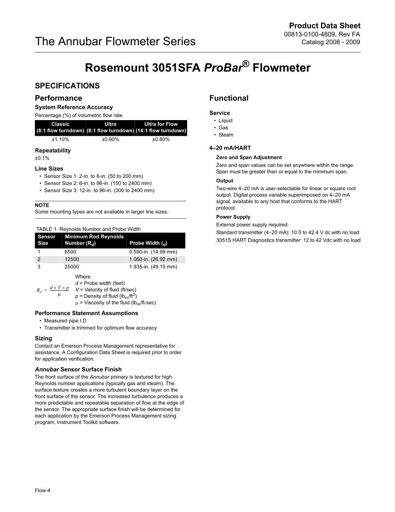
TABLE 1. Reynolds Number and Probe Width
Performance Statement Assumptions
• Measured pipe I.D
• Transmitter is trimmed for optimum flow accuracy
Sizing
Contact an Emerson Process Management representative for
assistance. A Configuration Data Sheet is required prior to order
for application verification.
Annubar Sensor Surface Finish
The front surface of the Annubar primary is textured for high
Reynolds number applications (typically gas and steam). The
surface texture creates a more turbulent boundary layer on the
front surface of the sensor. The increased turbulence produces a
more predictable and repeatable separation of flow at the edge of
the sensor. The appropriate surface finish will be determined for
each application by the Emerson Process Management sizing
program, Instrument Toolkit software.
Functional
Service
• Liquid
• Gas
• Steam
4–20 mA/HART
Zero and Span Adjustment
Zero and span values can be set anywhere within the range.
Span must be greater than or equal to the minimum span.
Output
Two-wire 4–20 mA is user-selectable for linear or square root
output. Digital process variable superimposed on 4–20 mA
signal, available to any host that conforms to the HART
protocol.
Power Supply
External power supply required.
Standard transmitter (4–20 mA): 10.5 to 42.4 V dc with no load
3051S HART Diagnostics transmitter: 12 to 42 Vdc with no load
System Reference Accuracy
Percentage (%) of volumetric flow rate
Classic
(8:1 flow turndown)
Ultra
(8:1 flow turndown)
Ultra for Flow
(14:1 flow turndown)
±1.10% ±0.90% ±0.80%
Sensor
Size
Minimum Rod Reynolds
Number (Rd) Probe Width (d)
1 6500 0.590-in. (14.99 mm)
2 12500 1.060-in. (26.92 mm)
3 25000 1.935-in. (49.15 mm)
Where
d = Probe width (feet)
V = Velocity of fluid (ft/sec)
p = Density of fluid (lbm/ft3)
μ = Viscosity of the fluid (lbm/ft-sec)
Rd
d V× p×
μ----------------------=
Flow-4
Product Data Sheet00813-0100-4809, Rev FA
Catalog 2008 - 2009 The Annubar Flowmeter Series
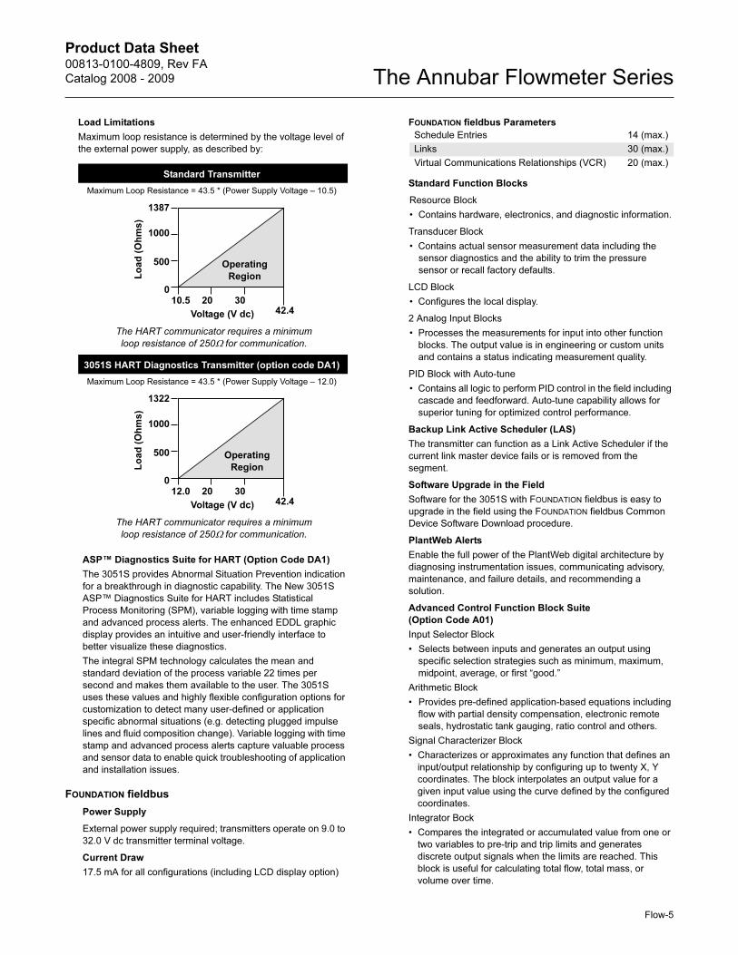
Load Limitations
Maximum loop resistance is determined by the voltage level of
the external power supply, as described by:
ASP™ Diagnostics Suite for HART (Option Code DA1)
The 3051S provides Abnormal Situation Prevention indication
for a breakthrough in diagnostic capability. The New 3051S
ASP™ Diagnostics Suite for HART includes Statistical
Process Monitoring (SPM), variable logging with time stamp
and advanced process alerts. The enhanced EDDL graphic
display provides an intuitive and user-friendly interface to
better visualize these diagnostics.
The integral SPM technology calculates the mean and
standard deviation of the process variable 22 times per
second and makes them available to the user. The 3051S
uses these values and highly flexible configuration options for
customization to detect many user-defined or application
specific abnormal situations (e.g. detecting plugged impulse
lines and fluid composition change). Variable logging with time
stamp and advanced process alerts capture valuable process
and sensor data to enable quick troubleshooting of application
and installation issues.
FOUNDATION fieldbus
Power Supply
External power supply required; transmitters operate on 9.0 to
32.0 V dc transmitter terminal voltage.
Current Draw
17.5 mA for all configurations (including LCD display option)
FOUNDATION fieldbus Parameters
Standard Function Blocks
Resource Block
• Contains hardware, electronics, and diagnostic information.
Transducer Block
• Contains actual sensor measurement data including the
sensor diagnostics and the ability to trim the pressure
sensor or recall factory defaults.
LCD Block
• Configures the local display.
2 Analog Input Blocks
• Processes the measurements for input into other function
blocks. The output value is in engineering or custom units
and contains a status indicating measurement quality.
PID Block with Auto-tune
• Contains all logic to perform PID control in the field including
cascade and feedforward. Auto-tune capability allows for
superior tuning for optimized control performance.
Backup Link Active Scheduler (LAS)
The transmitter can function as a Link Active Scheduler if the
current link master device fails or is removed from the
segment.
Software Upgrade in the Field
Software for the 3051S with FOUNDATION fieldbus is easy to
upgrade in the field using the FOUNDATION fieldbus Common
Device Software Download procedure.
PlantWeb Alerts
Enable the full power of the PlantWeb digital architecture by
diagnosing instrumentation issues, communicating advisory,
maintenance, and failure details, and recommending a
solution.
Advanced Control Function Block Suite
(Option Code A01)
Input Selector Block
• Selects between inputs and generates an output using
specific selection strategies such as minimum, maximum,
midpoint, average, or first “good.”
Arithmetic Block
• Provides pre-defined application-based equations including
flow with partial density compensation, electronic remote
seals, hydrostatic tank gauging, ratio control and others.
Signal Characterizer Block
• Characterizes or approximates any function that defines an
input/output relationship by configuring up to twenty X, Y
coordinates. The block interpolates an output value for a
given input value using the curve defined by the configured
coordinates.
Integrator Bock
• Compares the integrated or accumulated value from one or
two variables to pre-trip and trip limits and generates
discrete output signals when the limits are reached. This
block is useful for calculating total flow, total mass, or
volume over time.
Standard Transmitter
Maximum Loop Resistance = 43.5 * (Power Supply Voltage – 10.5)
The HART communicator requires a minimum
loop resistance of 250Ω for communication.
3051S HART Diagnostics Transmitter (option code DA1)
Maximum Loop Resistance = 43.5 * (Power Supply Voltage – 12.0)
The HART communicator requires a minimum
loop resistance of 250Ω for communication.
Voltage (V dc)
Lo
ad
(O
hm
s)
Operating
Region
1387
1000
500
010.5 20 30
42.4
Voltage (V dc)
Lo
ad
(O
hm
s)
Operating
Region
1322
1000
500
012.0 20 30
42.4
Schedule Entries 14 (max.)
Links 30 (max.)
Virtual Communications Relationships (VCR) 20 (max.)
Flow-5
Product Data Sheet00813-0100-4809, Rev FA
Catalog 2008 - 2009The Annubar Flowmeter Series
Output Splitter Block
• Splits the output of one PID or other control block so that the
PID will control two valves or other actuators.
Control Selector Block
• Selects one of up to three inputs (highest, middle, or lowest)
that are normally connected to the outputs of PID or other
control function blocks.
Fully Compensated Mass Flow Block (Option Code H01)
Calculates fully compensated mass flow based on differential
pressure with external process pressure and temperature
measurements over the fieldbus segment. Configuration for
the mass flow calculation is easily accomplished using the
Rosemount Engineering Assistant.
ASP™ Diagnostics Suite for FOUNDATION fieldbus
(Option Code D01)
3051S FOUNDATION fieldbus Diagnostics provide Abnormal
Situation Prevention (ASP) indication and enhanced EDDL
graphic displays for easy visual analysis.
The integral statistical process monitoring (SPM) technology
calculates the mean and standard deviation of the process
variable 22 times per second and makes them available to the
user. The 3051S ASP algorithm uses these values and highly
flexible configuration options for customization to detect many
user-defined or application specific abnormal situations (e.g.
detecting plugged impulse lines and fluid composition
change).
Wireless Self-Organizing Networks
Output
Wireless enabled HART.
Transmit Rate
User selectable, 15 sec. to 60 min.
Power Module
Process Temperature Limits
Direct Mount Transmitter
• 500 °F (260 °C)
• 750 °F (398 °C) when used with a direct mount, high
temperature 5-valve manifold (Transmitter Connection
Platform code 6)
Remote Mount Transmitter
• 1250 °F (677 °C) – Hastelloy® Sensor Material
• 850 °F (454 °C) – Stainless Steel Sensor Material
Transmitter Temperature Limits
Ambient
• –40 to 185 °F (–40 to 85 °C)
• With Integral Display(1): –40 to 175 °F (–40 to 80 °C)
Storage
• –50 to 230 °F (–46 to 110 °C)
• With Integral Display: –40 to 185 °F (–40 to 85 °C)
• With wireless output (code X): –40 to 185 °F (–40 to 85 °C)
Pressure Limits(2)
Direct Mount Transmitter
• Pressure retention per ANSI B16.5 600# or DIN PN
Static Pressure Limits
• Range 1A: Operates within specification between static line
pressures of 0.5 psia to 2000 psig (0.03 to 138 bar)
• Ranges 2A– 3A: Operates within specifications between
static line pressures of 0.5 psia and 3626 psig (0.03 bar-A to
250 bar-G)
Burst Pressure Limits
Coplanar or traditional process flange
• 10000 psig (689,5 bar).
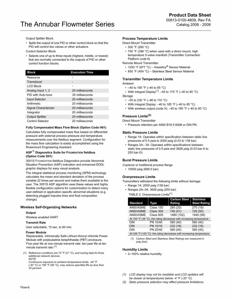
Overpressure Limits
Transmitters withstand the following limits without damage:
• Range 1A: 2000 psig (138 bar)
• Ranges 2A–3A: 3626 psig (250 bar)
Humidity Limits
• 0–100% relative humidity
Block Execution Time
Resource -
Transducer -
LCD Block -
Analog Input 1, 2 20 milliseconds
PID with Auto-tune 35 milliseconds
Input Selector 20 milliseconds
Arithmetic 20 milliseconds
Signal Characterizer 20 milliseconds
Integrator 20 milliseconds
Output Splitter 20 milliseconds
Control Selector 20 milliseconds
Replaceable, Intrinsically Safe Lithium-thionyl chloride Power
Module with polybutadine terephthalate (PBT) enclosure.
Five-year life at one minute transmit rate: ten-year life at ten
minute transmit rate.(1)
(1) Reference conditions are 70 °F (21 °C), and routing data for three additional network devices.NOTEContinuous exposure to ambient temperature limits, -40 °F (-40 °C) or 185 °F (85 °C), may reduce specified life by less than 20 percent.
(1) LCD display may not be readable and LCD updates will
be slower at temperatures below -4 °F (-20 °C).
(2) Static pressure selection may effect pressure limitations.
TABLE 2. Overpressure Limits(1)
(1) Carbon Steel and Stainless Steel Ratings are measured in psig (bar).
Standard Type
Carbon Steel
Rating
Stainless
Steel Rating
ANSI/ASME Class 150 285 (20) 275 (19)
ANSI/ASME Class 300 740 (51) 720 (50)
ANSI/ASME Class 600 1480 (102) 1440 (99)
At 100 °F (38 °C), the rating decreases with increasing temperature.
DIN PN 10/40 580 (40) 580 (40)
DIN PN 10/16 232 (16) 232 (16)
DIN PN 25/40 580 (40) 580 (40)
At 248 °F (120 °C), the rating decreases with increasing temperature.
Flow-6
Product Data Sheet00813-0100-4809, Rev FA
Catalog 2008 - 2009 The Annubar Flowmeter Series
Turn-On Time
Performance within specifications less than 2 seconds (typical)
after power is applied to the transmitter
Damping
Analog output response to a step input change is user-selectable
from 0 to 60 seconds for one time constant. This software damping
is in addition to sensor module response time
Failure Mode Alarm
HART 4-20mA (output option codes A and B)
If self-diagnostics detect a gross transmitter failure, the analog
signal will be driven offscale to alert the user. Rosemount
standard (default), NAMUR, and custom alarm levels are
available (see Table 3).
High or low alarm signal is software-selectable or
hardware-selectable via the optional switch (option D1).
3051S Safety-Certified Transmitter Failure Values
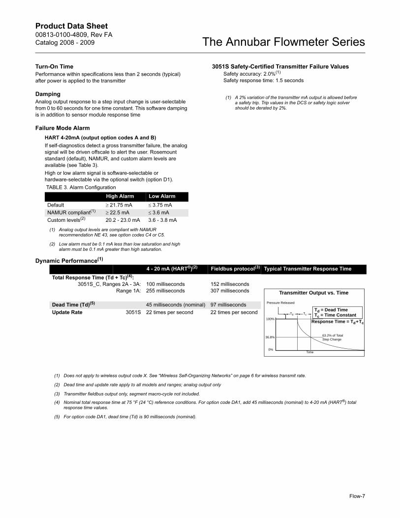
Dynamic Performance(1)
TABLE 3. Alarm Configuration
High Alarm Low Alarm
Default ≥ 21.75 mA ≤ 3.75 mA
NAMUR compliant(1)
(1) Analog output levels are compliant with NAMUR recommendation NE 43, see option codes C4 or C5.
≥ 22.5 mA ≤ 3.6 mA
Custom levels(2)
(2) Low alarm must be 0.1 mA less than low saturation and high alarm must be 0.1 mA greater than high saturation.
20.2 - 23.0 mA 3.6 - 3.8 mA
Safety accuracy: 2.0%(1)
Safety response time: 1.5 seconds
(1) A 2% variation of the transmitter mA output is allowed before a safety trip. Trip values in the DCS or safety logic solver should be derated by 2%.
(1)
(1) Does not apply to wireless output code X. See “Wireless Self-Organizing Networks” on page 6 for wireless transmit rate.
4 - 20 mA (HART®)(2)
(2) Dead time and update rate apply to all models and ranges; analog output only
Fieldbus protocol(3)
(3) Transmitter fieldbus output only, segment macro-cycle not included.
Typical Transmitter Response Time
Total Response Time (Td + Tc)(4):
3051S_C, Ranges 2A - 3A:
Range 1A:
(4) Nominal total response time at 75 °F (24 °C) reference conditions. For option code DA1, add 45 milliseconds (nominal) to 4-20 mA (HART®) total response time values.
100 milliseconds
255 milliseconds
152 milliseconds
307 milliseconds
Dead Time (Td)(5)
(5) For option code DA1, dead time (Td) is 90 milliseconds (nominal).
45 milliseconds (nominal) 97 milliseconds
Update Rate 3051S 22 times per second 22 times per second TcTd
Td = Dead TimeTc = Time Constant
Pressure Released
Response Time = Td+Tc
63.2% of TotalStep Change
Time0%
100%
36.8%
Transmitter Output vs. Time
Flow-7
Product Data Sheet00813-0100-4809, Rev FA
Catalog 2008 - 2009The Annubar Flowmeter Series
Physical
Temperature Measurement
Integral RTD
• 100 Ohm platinum RTD
• 4-wire RTD (α = 0.00385)
Remote RTD
• 100 Ohm platinum RTD, spring loaded with 1/2-in.
NPT nipple and union (078 series with Rosemount 644
housing)
Thermowell with Remote RTD
• 1/2-in. x 1/2-in NPT, 316 Stainless Steel with 1/2-in. weld couplet
to match pipe material
Housing Connections1/2–14 NPT, G1/2, and M20 × 1.5 (CM20) conduit. HART interface
connections fixed to terminal block for output code A
Annubar Sensor Material
• 316 Stainless Steel
• Hastelloy 276
Annubar Type
See “Dimensional Drawings” on page 15
Pak-Lok Model (option P)
• Provided with a compression sealing mechanism rated up to
600# ANSI (1440 psig at 100 °F (99 bar at 38 °C))
• Graphite Packing (–300 to 850 °F (–184 to 454 °C))
Flanged with Opposite Side Support Model (option F)
• Provided with opposite side support, which is the same
material as the pipe and requires a second pipe penetration
• Sensor flange is the same material as the Annubar sensor and
the mounting flange is the same material as the pipe material
• Flanged mounting hardware: nuts, studs and gaskets (DIN
units supplied without nuts, studs and gaskets)
• SST: (–300 to 850 °F (–184 to 454 °C))
• Hastelloy: (–300 to 1250 °F (–184 to 677 °C))
Flange–Lok Model (option L)
• Flange–Lok assembly is supplied in 316 SST material.
• Flange-Lok mounting hardware: nuts, studs and gaskets (DIN
units supplied without nuts, studs and gaskets)
• –300 to 850 °F (–184 to 454 °C)
Flo-Tap Models (options G and M)
• Opposite side support is not available
• Threaded connection is not available with Sensor Size 3
• Gear Drive is not available with Sensor Size 1
• Packing gland required
• Packing Gland Material Temperature Limits
• PTFE: –40 to 400 °F (–40 to 204 °C)
• Graphite: –300 to 850 °F (–184 to 454 °C)
• Isolation valve included
• The isolation valve will carry the same pressure rating as the
sensor flange and mounting flange specified in the mounting
type
• Ball valves have a 300# limitation
• For threaded flo-tap models, the isolation valve NPT size is
11/4-in. (Sensor Size one) and 2-in. (Sensor Size 2).
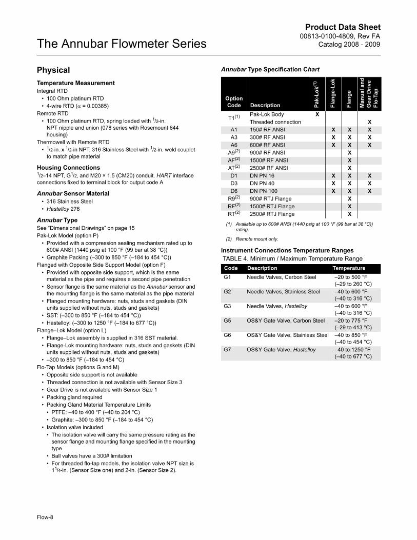
Annubar Type Specification Chart
Instrument Connections Temperature Ranges
Option
Code Description Pa
k-L
ok(1)
(1) Available up to 600# ANSI (1440 psig at 100 °F (99 bar at 38 °C)) rating.
Fla
ng
e-L
ok
Fla
ng
e
Ma
nu
al
an
d
Ge
ar
Dri
ve
Flo
-Ta
p
T1(1) Pak-Lok Body X
Threaded connection X
A1 150# RF ANSI X X X
A3 300# RF ANSI X X X
A6 600# RF ANSI X X X
A9(2)
(2) Remote mount only.
900# RF ANSI X
AF(2) 1500# RF ANSI X
AT(2) 2500# RF ANSI X
D1 DN PN 16 X X X
D3 DN PN 40 X X X
D6 DN PN 100 X X X
R9(2) 900# RTJ Flange X
RF(2) 1500# RTJ Flange X
RT(2) 2500# RTJ Flange X
TABLE 4. Minimum / Maximum Temperature Range
Code Description Temperature
G1 Needle Valves, Carbon Steel –20 to 500 °F
(–29 to 260 °C)
G2 Needle Valves, Stainless Steel –40 to 600 °F
(–40 to 316 °C)
G3 Needle Valves, Hastelloy –40 to 600 °F
(–40 to 316 °C)
G5 OS&Y Gate Valve, Carbon Steel –20 to 775 °F
(–29 to 413 °C)
G6 OS&Y Gate Valve, Stainless Steel –40 to 850 °F
(–40 to 454 °C)
G7 OS&Y Gate Valve, Hastelloy –40 to 1250 °F
(–40 to 677 °C)
Flow-8
Product Data Sheet00813-0100-4809, Rev FA
Catalog 2008 - 2009 The Annubar Flowmeter Series
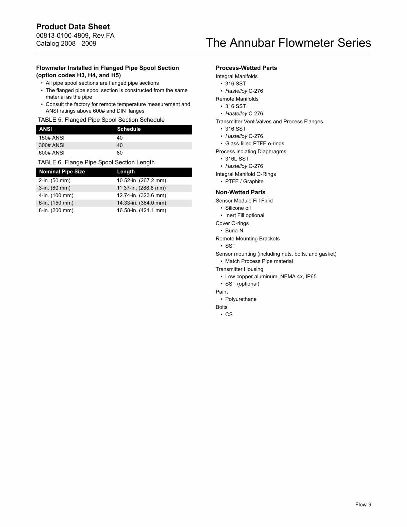
Flowmeter Installed in Flanged Pipe Spool Section
(option codes H3, H4, and H5)
• All pipe spool sections are flanged pipe sections
• The flanged pipe spool section is constructed from the same
material as the pipe
• Consult the factory for remote temperature measurement and
ANSI ratings above 600# and DIN flanges
Process-Wetted Parts
Integral Manifolds
• 316 SST
• Hastelloy C-276
Remote Manifolds
• 316 SST
• Hastelloy C-276
Transmitter Vent Valves and Process Flanges
• 316 SST
• Hastelloy C-276
• Glass-filled PTFE o-rings
Process Isolating Diaphragms
• 316L SST
• Hastelloy C-276
Integral Manifold O-Rings
• PTFE / Graphite
Non-Wetted Parts
Sensor Module Fill Fluid
• Silicone oil
• Inert Fill optional
Cover O-rings
• Buna-N
Remote Mounting Brackets
• SST
Sensor mounting (including nuts, bolts, and gasket)
• Match Process Pipe material
Transmitter Housing
• Low copper aluminum, NEMA 4x, IP65
• SST (optional)
Paint
• Polyurethane
Bolts
• CS
TABLE 5. Flanged Pipe Spool Section Schedule
ANSI Schedule
150# ANSI 40
300# ANSI 40
600# ANSI 80
TABLE 6. Flange Pipe Spool Section Length
Nominal Pipe Size Length
2-in. (50 mm) 10.52-in. (267.2 mm)
3-in. (80 mm) 11.37-in. (288.8 mm)
4-in. (100 mm) 12.74-in. (323.6 mm)
6-in. (150 mm) 14.33-in. (364.0 mm)
8-in. (200 mm) 16.58-in. (421.1 mm)
Flow-9
Product Data Sheet00813-0100-4809, Rev FA
Catalog 2008 - 2009The Annubar Flowmeter Series
Flow-10
Drill Hole Size According to Sensor Size
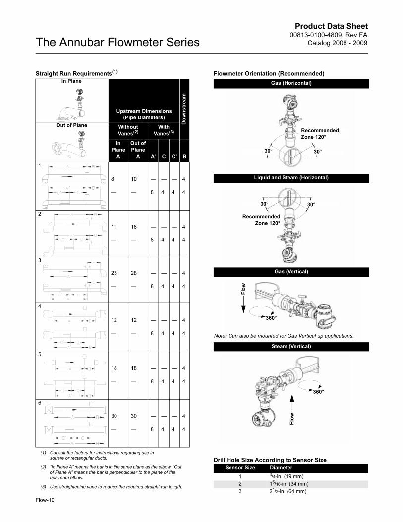
Straight Run Requirements(1)
(1) Consult the factory for instructions regarding use in square or rectangular ducts.
Upstream Dimensions
(Pipe Diameters)
Do
wn
str
ea
m
Without
Vanes(2)
(2) “In Plane A” means the bar is in the same plane as the elbow. “Out of Plane A” means the bar is perpendicular to the plane of the upstream elbow.
With
Vanes(3)
(3) Use straightening vane to reduce the required straight run length.
In
Plane
A
Out of
Plane
A A’ C C’ B
1
8
—
10
—
—
8
—
4
—
4
4
4
2
11
—
16
—
—
8
—
4
—
4
4
4
3
23
—
28
—
—
8
—
4
—
4
4
4
4
12
—
12
—
—
8
—
4
—
4
4
4
5
18
—
18
—
—
8
—
4
—
4
4
4
6
30
—
30
—
—
8
—
4
—
4
4
4
Flowmeter Orientation (Recommended)
Gas (Horizontal)
Liquid and Steam (Horizontal)
Gas (Vertical)
Steam (Vertical)
Sensor Size Diameter
1 3/4-in. (19 mm)
2 15/16-in. (34 mm)
3 21/2-in. (64 mm)
30° 30°
Recommended
Zone 120°
30° 30°
Recommended
Zone 120°
Flo
w
360°
Note: Can also be mounted for Gas Vertical up applications.
360°
Flo
w
In Plane
Out of Plane
Product Data Sheet00813-0100-4809, Rev FA
Catalog 2008 - 2009 The Annubar Flowmeter Series
Flow-11
PRODUCT CERTIFICATIONS
Approved Manufacturing LocationsRosemount Inc. — Chanhassen, Minnesota USA
Emerson Process Management GmbH & Co. — Wessling,
Germany
Emerson Process Management Asia Pacific Private Limited —
Singapore
Beijing Rosemount Far East Instrument Co., LTD — Beijing, China
European Directive InformationThe EC declaration of conformity for all applicable European
directives for this product can be found at www.rosemount.com. A
hard copy may be obtained by contacting an Emerson Process
Management representative.
ATEX Directive (94/9/EC)
Emerson Process Management complies with the
ATEX Directive.
European Pressure Equipment Directive (PED) (97/23/EC)
Models 3051S_CA4; 3051S_CD2, 3, 4, 5; (also with P9 option)
Pressure Transmitters — QS Certificate of Assessment -
EC No. PED-H-20, Module H Conformity Assessment
All other Model 3051S Pressure Transmitters
— Sound Engineering Practice
Transmitter Attachments: Diaphragm Seal - Process Flange -
Manifold — Sound Engineering Practice
Primary Elements, Flowmeter
— See appropriate Primary Element QIG
Electro Magnetic Compatibility (EMC) (89/336/EEC)
All Models: EN 50081-1: 1992; EN 50082-2:1995;
EN 61326-1:1997 – Industrial
Ordinary Location Certification for FMAs standard, the transmitter has been examined and tested to
determine that the design meets basic electrical, mechanical, and
fire protection requirements by FM, a nationally recognized testing
laboratory (NRTL) as accredited by the Federal Occupational
Safety and Health Administration (OSHA).
Hazardous Locations Certifications
North American Certifications
FM Approvals
E5 Explosion-proof for Class I, Division 1, Groups B, C, and D;
dust-ignition proof for Class II and Class III, Division 1,
Groups E, F, and G; hazardous locations; enclosure Type
4X, conduit seal not required when installed according to
Rosemount drawing 03151-1003.
I5/IE Intrinsically Safe for use in Class I, Division 1, Groups A, B,
C, and D; Class II, Division 1, Groups E, F, and G; Class III,
Division 1; Class I, Zone 0 AEx ia IIC when connected in
accordance with Rosemount drawing 03151-1006;
Non-incendive for Class I, Division 2, Groups A, B, C, and D
Enclosure Type 4X
For entity parameters see control drawing 03151-1006.
Canadian Standards Association (CSA)
E6 Explosion-proof for Class I, Division 1, Groups B, C, and D;
Dust-Ignition-Proof for Class II and Class III, Division 1,
Groups E, F, and G; suitable for Class I, Division 2, Groups
A, B, C, and D, when installed per Rosemount drawing
03151-1013, CSA Enclosure Type 4X; conduit seal not
required.
I6/IF Intrinsically Safe for Class I, Division 1, Groups A, B, C, and
D when connected in accordance with Rosemount drawings
03151-1016;
For entity parameters see control drawing 03151-1016.
European Certifications
I1/IA ATEX Intrinsic Safety
Certificate No.: BAS01ATEX1303X II 1G
EEx ia IIC T4 (Ta = -60 °C to 70 °C) -HART/Remote
Display/Quick Connect/HART Diagnostics
EEx ia IIC T4 (Ta = -60 °C to 70 °C) -FOUNDATION fieldbus
EEx ia IIC T4 (Ta = -60 °C to 40 °C) -FISCO
IP66
1180
Special conditions for safe use (x)
1. The apparatus, excluding the Types 3051 S-T and 3051
S-C (In-line and Coplanar SuperModules respectively), is
not capable of withstanding the 500V test as defined in
Clause 6.4.12 of EN 50020. This must be considered
during installation.
2. The terminal pins of the Types 3051 S-T and 3051 S-C
must be protected to IP20 minimum.
TABLE 7. Input Parameters
Loop / Power Groups
Ui = 30 V HART / FOUNDATION fieldbus/ Remote
Display / Quick Connect / HART
Diagnostics
Ui = 17.5 V FISCO
Ii = 300 mA HART / FOUNDATION fieldbus/ Remote
Display / Quick Connect / HART
Diagnostics
Ii = 380 mA FISCO
Pi = 1.0 W HART / Remote Display / Quick Connect /
HART Diagnostics
Pi = 1.3 W FOUNDATION fieldbus
Pi = 5.32 W FISCO
Ci = 30 nF SuperModule Platform / Quick Connect
Ci = 11.4 nF HART / HART Diagnostics
Ci = 0 FOUNDATION fieldbus / Remote Display /
FISCO
Li = 0 HART / FOUNDATION fieldbus/ FISCO /
Quick Connect / HART Diagnostics
Li = 60 µH Remote Display
Product Data Sheet00813-0100-4809, Rev FA
Catalog 2008 - 2009The Annubar Flowmeter Series
N1 ATEX Type n
Certificate No.: BAS01ATEX3304X II 3 G
EEx nL IIC T5 (Ta = -40 °C TO 70 °C)
Ui = 45 Vdc max
IP66
Special conditions for safe use (x)
The apparatus is not capable of withstanding the 500V
insulation test required by Clause 9.1 of EN 50021: 1999.
This must be taken into account when installing the
apparatus.
ND ATEX Dust
Certificate No.: BAS01ATEX1374X II 1 D
T105°C (-20 °C ≤ Tamb ≤ 85 °C)
Vmax = 42.4 volts max
A = 22 mA
IP66
1180
Special conditions for safe use (x)
1. The user must ensure that the maximum rated voltage
and current (42.4 volts, 22 milliampere, DC) are not
exceeded. All connections to other apparatus or
associated apparatus shall have control over this voltage
and current equivalent to a category “ib” circuit according
to EN 50020.
2. Cable entries must be used which maintain the ingress
protection of the enclosure to at least IP66.
3. Unused cable entries must be filled with suitable blanking
plugs which maintain the ingress protection of the
enclosure to at least IP66.
4. Cable entries and blanking plugs must be suitable for the
ambient range of the apparatus and capable of
withstanding a 7J impact test.
5. The 3051S must be securely screwed in place to maintain
the ingress protection of the enclosure.
E1 ATEX Flameproof
Certificate No.: KEMA00ATEX2143X II 1/2 G
EEx d IIC T6 (-50 °C ≤ Tamb ≤ 65 °C)
EEx d IIC T5 (-50 °C ≤ Tamb ≤ 80 °C)
Vmax = 42.4V
1180
Special conditions for safe use (x)
This device contains a thin wall diaphragm. Installation,
maintenance and use shall take into account the
environmental conditions to which the diaphragm will be
subjected. The manufacturer’s instructions for installation
and maintenance shall be followed in detail to assure safety
during its expected lifetime. The Model 3051S pressure
transmitter must include a Series 300S housing integrally
mounted to a Series Model 3051S Sensor module as per
Rosemount drawing 03151-1023.
Japanese Certifications
E4 TIIS Flameproof
Ex d IIC T6
Australian Certifications
E7 SAA Flameproof and Dust Ignition-proof
Certification No.: AUS Ex 3798X
Ex d IIC T6 (Ta = 60°C) IP66
DIP A21 TA T6 (Ta = 60°C) IP66
Special conditions for safe use (x)
1. It is a condition of safe use that each housing shall be
connected to external circuits via suitable conduit or
Standards Australia certified cable glands. Where only one
entry is used for connection to external circuits, the unused
entry shall be closed by means of the blanking plug
supplied by the equipment manufacturer or by a suitable
Standards Australia certified blanking plug.
2. It is a condition of safe use that a dielectric strength test
shall be applied whenever the terminal block is changed or
replaced in either the dual compartment or single
compartment housings. The breakdown current shall be
less than 5 mA, when 500 V, 47 to 62 Hz, is applied for one
minute. Note: if tested with an optional T1 transient
protector terminal block fitted, the protection will operate
and hence there will be no current indicated.
3. It is a condition of safe use that each transmitter module
shall be used with a Model 300S housing, in order to
comply with flameproof requirements.
4. It is a condition of safe use that each model 300S housing
fitted with a transmitter module shall be marked with the
same certification marking code information. Should the
housing be replaced after initial supply to another model
300S housing, the replacement housing shall have the
same certification marking code information as the
housing it replaces.
Certificate Description
TC15682 Coplanar with Junction Box Housing
TC15683 Coplanar with PlantWeb Housing
TC15684 Coplanar with PlantWeb Housing
and LCD Display
TC15685 In-Line SST with Junction Box Housing
TC15686 In-Line Hastelloy with Junction Box Housing
TC15687 In-Line SST with PlantWeb Housing
TC15688 In-Line Hastelloy with Plantweb Housing
TC15689 In-Line SST with Plantweb Housing
and LCD Display
TC15690 In-Line Hastelloy with PlantWeb Housing
and LCD Display
Flow-12
Product Data Sheet00813-0100-4809, Rev FA
Catalog 2008 - 2009 The Annubar Flowmeter Series
IECEx Certifications
I7/IG IECEx Intrinsic Safety
Certificate No.: IECExBAS04.0017X
Ex ia IIC T4 (Ta = -60 °C to 70 °C) -HART/Remote
Display/Quick Connect/HART Diagnostics
Ex ia IIC T4 (Ta = -60 °C to 70 °C) -FOUNDATION fieldbus
Ex ia IIC T4 (Ta = -60 °C to 40 °C) -FISCO
IP66
Special conditions for safe use (x)
1. The Models 3051S HART 4-20mA, 3051S fieldbus, 3051S
Profibus and 3051S FISCO are not capable of
withstanding the 500V test as defined in clause 6.4.12 of
IEC 60079-11. This must be taken into account during
installation.
2. The terminal pins of the Types 3051S-T and 3051S-C
must be protected to IP20 minimum.
N7 IECEx Type n
Certificate No.: IECExBAS04.0018X
Ex nC IIC T5 (Ta = -40 °C to 70 °C)
Ui = 45 Vdc MAX
IP66
Special conditions for safe use (x)
The apparatus is not capable of withstanding the 500 V
insulation test required by Clause 8 of IEC 79-15: 1987.
Combinations of Certifications
Stainless steel certification tag is provided when optional approval
is specified. Once a device labeled with multiple approval types is
installed, it should not be reinstalled using any other approval
types. Permanently mark the approval label to distinguish it from
unused approval types.
K1 Combination of E1, I1, N1, and ND
K5 Combination of E5 and I5
K6 Combination of E6 and I6
K7 Combination of E7, I7, and N7
KA Combination of E1, I1, E6, and I6
KB Combination of E5, I5, I6 and E6
KC Combination of E5, E1, I5 and I1
KD Combination of E5, I5, E6, I6, E1, and I1
TABLE 8. Input Parameters
Loop / Power Groups
Ui = 30 V HART / FOUNDATION fieldbus/
Remote Display / Quick Connect
/ HART Diagnostics
Ui = 17.5 V FISCO
Ii = 300 mA HART / FOUNDATION fieldbus/
Remote Display / Quick Connect
/ HART Diagnostics
Ii = 380 mA FISCO
Pi = 1.0 W HART / Remote Display / Quick
Connect / HART Diagnostics
Pi = 1.3 W FOUNDATION fieldbus
Pi = 5.32 W FISCO
Ci = 30 nF SuperModule Platform / Quick
Connect
Ci = 11.4 nF HART / HART Diagnostics
Ci = 0 FOUNDATION fieldbus / Remote
Display / FISCO / Quick Connect
/ HART Diagnostics
Li = 0 HART / FOUNDATION fieldbus /
FISCO / Quick Connect / HART
Diagnostics
Li = 60 H Remote Displayμ
Flow-13
Product Data Sheet00813-0100-4809, Rev FA
Catalog 2008 - 2009The Annubar Flowmeter Series
Flow-14
WIRELESS CERTIFICATIONS
Telecommunication Compliance
All wireless devices require certification to ensure that they adhere to
regulations regarding the use of the RF spectrum. Nearly every
country requires this type of product certification. Emerson is working
with governmental agencies around the world to supply fully
compliant products and remove the risk of violating country directives
or laws governing wireless device usage.
FCC and IC ApprovalsThis device complies with Part 15 of the FCC Rules. Operation is
subject to the following conditions: This device may not cause
harmful interference this device must accept any interference
received, including interference that may cause undesired operation.
This device must be installed to ensure a minimum antenna
separation distance of 20cm from all persons.
Ordinary Location Certification for FMAs standard, the transmitter has been examined and tested to
determine that the design meets basic electrical, mechanical, and fire
protection requirements by FM, a nationally recognized testing
laboratory (NRTL) as accredited by the Federal Occupational Safety
and Health Administration (OSHA).
European Directive InformationThe EC declaration of conformity for all applicable European
directives for this product can be found at www.rosemount.com. A
hard copy may be obtained by contacting an Emerson Process
Management representative.
ATEX Directive (94/9/EC)
Emerson Process Management complies with the ATEX Directive.
European Pressure Equipment Directive (PED) (97/23/EC)
Models 3051S_CA4; 3051S_CD2, 3, 4, 5; (also with P9 option)
Pressure Transmitters — QS Certificate of Assessment -
EC No. PED-H-100, Module H Conformity Assessment
All other Model 3051S Pressure Transmitters
— Sound Engineering Practice
Transmitter Attachments: Diaphragm Seal - Process Flange -
Manifold — Sound Engineering Practice
Primary Elements, Flowmeter
— See appropriate Primary Element QIG
Electro Magnetic Compatibility (EMC) (2004/108/EC)
All Models: EN 50081-1: 1992; EN 50082-2:1995;
EN 61326-1:1997 + A1, A2, and A3 – Industrial
Radio and Telecommunications Terminal Equipment Directive
(R&TTE)(1999/5/EC)
Emerson Process Management complies with the R&TTE
Directive.
Hazardous Locations Certifications
North American CertificationsFactory Mutual (FM) Approvals
I5 FM Intrinsically Safe, Non-Incendive, and Dust Ignition-proof.
Intrinsically Safe for Class I/II/III, Division 1,
Groups A, B, C, D, E, F, and G.
Zone Marking: Class I, Zone 0, AEx ia llC
Temperature Codes T4 (Tamb = -50 to 70° C)
Non-Incendive for Class I, Division 2, Groups A, B, C, and D.
Dust Ignition-proof for Class II/III, Division 1,
Groups E, F, and G.
Ambient temperature limits: -50 to 85° C
For use with Rosemount SmartPower options
00753-9220-XXXX only.
Enclosure Type 4X / IP66
CSA - Canadian Standards Association
I6 CSA Intrinsically Safe
Intrinsically Safe for Class I, Division 1, Groups A, B, C, and D.
Temp Code T3C
Enclosure Type 4X / IP66
For use with Rosemount SmartPower options
00753-9220-XXXX only.
European Certifications
I1 ATEX Intrinsic Safety
Certificate No.: BAS01ATEX1303X II 1G
Ex ia IIC T4 (Ta = -60 °C to 70 °C)
IP66
For use with Rosemount SmartPower options
00753-9220-XXXX only.
1180
IECEx Certifications
I7 IECEx Intrinsic Safety
Certificate No.: IECEx BAS 04.0017X
Ex ia IIC T4 (Ta = -60 °C to 70 °C)
For use with Rosemount SmartPower options
00753-9220-XXXX only.
IP66
Country Restriction
Bulgaria General authorization required for outdoor use and public service
France Outdoor use limited to 10mW e.i.r.p.
Italy If used outside of own premises, general authorization is required.
Norway May be restricted in the geographical area within a radius of 20 km from the center of Ny-Alesund.
Romania Use on a secondary basis. Individual license required.
Radio Power Label (See
Figure 1) indicates output
power configuration of the radio.
Devices with this label are
configured for output power less
than 10 mW e.i.r.p. At time of
purchase the customer must
specify ultimate country of
installation and operation.
Radio Power Label
Figure 1.
Product Data Sheet00813-0100-4809, Rev FA
Catalog 2008 - 2009 The Annubar Flowmeter Series
Flow-15
DIMENSIONAL DRAWINGS
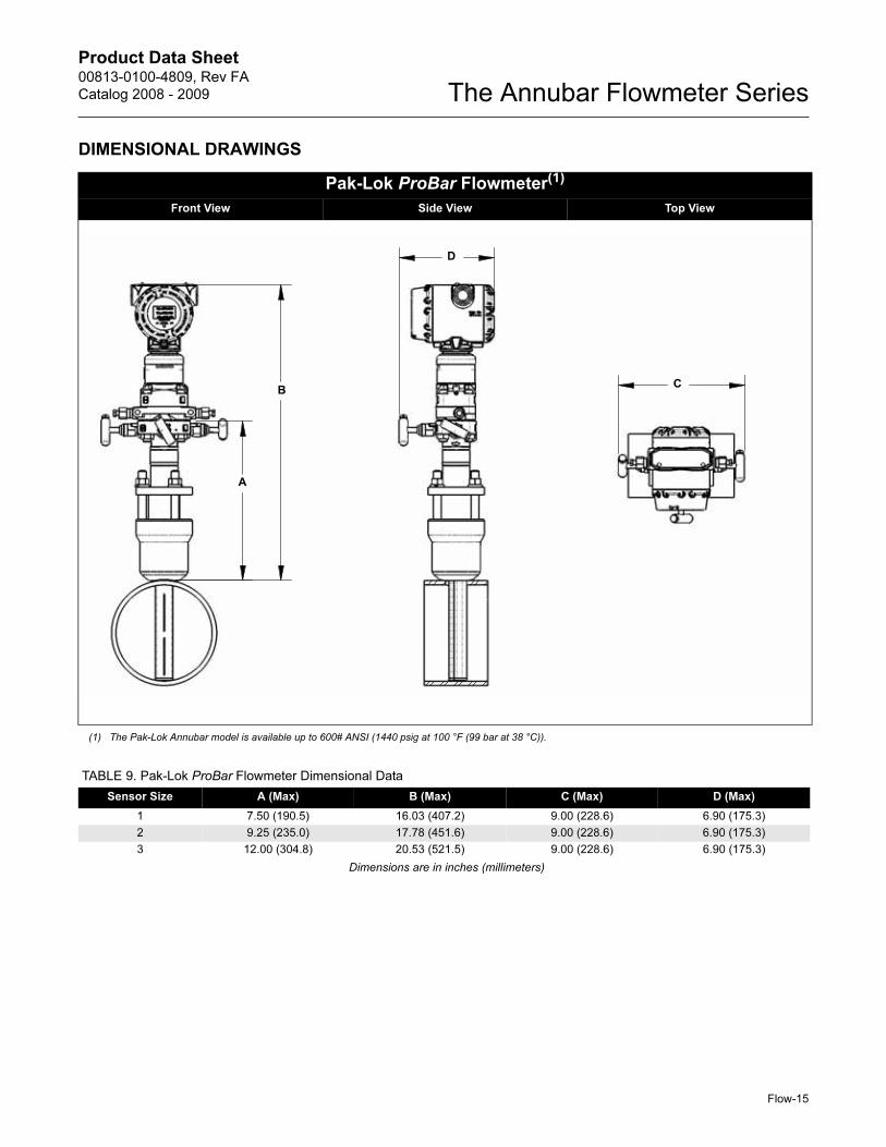
Pak-Lok ProBar Flowmeter(1)
Front View Side View Top View
(1) The Pak-Lok Annubar model is available up to 600# ANSI (1440 psig at 100 °F (99 bar at 38 °C)).
B
A
D
C
TABLE 9. Pak-Lok ProBar Flowmeter Dimensional Data
Sensor Size A (Max) B (Max) C (Max) D (Max)
1 7.50 (190.5) 16.03 (407.2) 9.00 (228.6) 6.90 (175.3)
2 9.25 (235.0) 17.78 (451.6) 9.00 (228.6) 6.90 (175.3)
3 12.00 (304.8) 20.53 (521.5) 9.00 (228.6) 6.90 (175.3)
Dimensions are in inches (millimeters)
Product Data Sheet00813-0100-4809, Rev FA
Catalog 2008 - 2009The Annubar Flowmeter Series
Flow-16
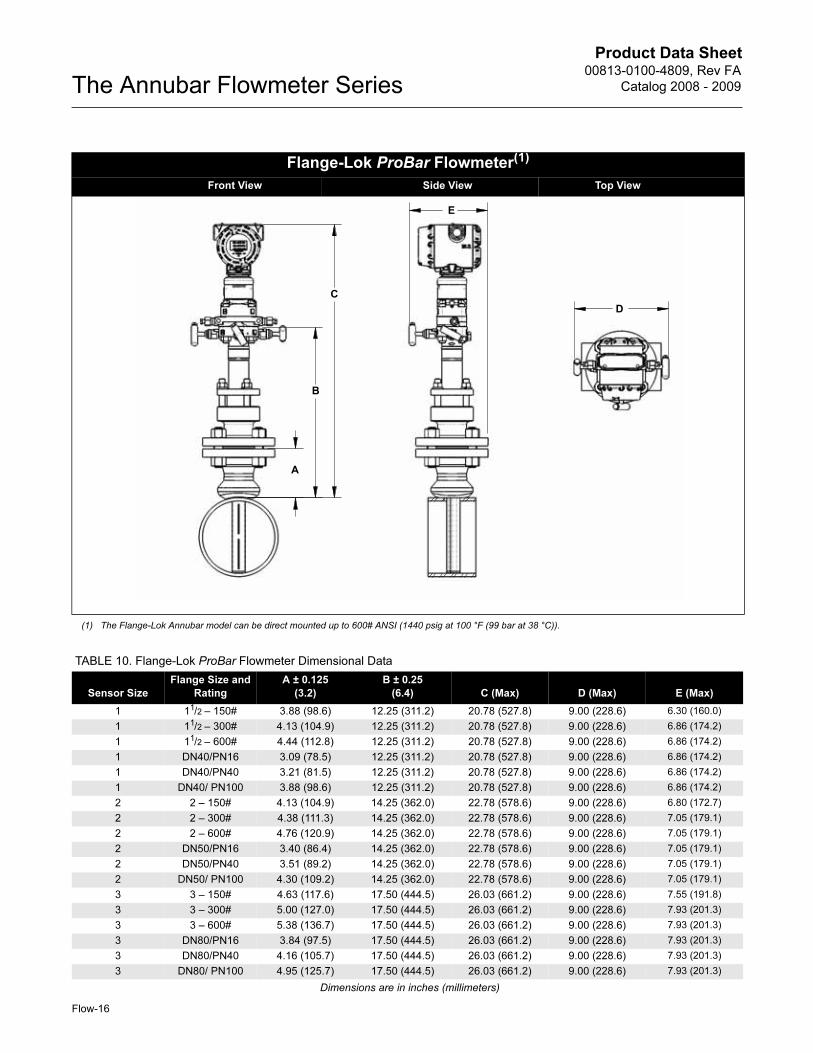
Flange-Lok ProBar Flowmeter(1)
_____________Front View ______Side View Top View________
(1) The Flange-Lok Annubar model can be direct mounted up to 600# ANSI (1440 psig at 100 °F (99 bar at 38 °C)).
B
A
D
C
E
TABLE 10. Flange-Lok ProBar Flowmeter Dimensional Data
Sensor Size
Flange Size and
Rating
A ± 0.125
(3.2)
B ± 0.25
(6.4) C (Max) D (Max) E (Max)
1 11/2 – 150# 3.88 (98.6) 12.25 (311.2) 20.78 (527.8) 9.00 (228.6) 6.30 (160.0)
1 11/2 – 300# 4.13 (104.9) 12.25 (311.2) 20.78 (527.8) 9.00 (228.6) 6.86 (174.2)
1 11/2 – 600# 4.44 (112.8) 12.25 (311.2) 20.78 (527.8) 9.00 (228.6) 6.86 (174.2)
1 DN40/PN16 3.09 (78.5) 12.25 (311.2) 20.78 (527.8) 9.00 (228.6) 6.86 (174.2)
1 DN40/PN40 3.21 (81.5) 12.25 (311.2) 20.78 (527.8) 9.00 (228.6) 6.86 (174.2)
1 DN40/ PN100 3.88 (98.6) 12.25 (311.2) 20.78 (527.8) 9.00 (228.6) 6.86 (174.2)
2 2 – 150# 4.13 (104.9) 14.25 (362.0) 22.78 (578.6) 9.00 (228.6) 6.80 (172.7)
2 2 – 300# 4.38 (111.3) 14.25 (362.0) 22.78 (578.6) 9.00 (228.6) 7.05 (179.1)
2 2 – 600# 4.76 (120.9) 14.25 (362.0) 22.78 (578.6) 9.00 (228.6) 7.05 (179.1)
2 DN50/PN16 3.40 (86.4) 14.25 (362.0) 22.78 (578.6) 9.00 (228.6) 7.05 (179.1)
2 DN50/PN40 3.51 (89.2) 14.25 (362.0) 22.78 (578.6) 9.00 (228.6) 7.05 (179.1)
2 DN50/ PN100 4.30 (109.2) 14.25 (362.0) 22.78 (578.6) 9.00 (228.6) 7.05 (179.1)
3 3 – 150# 4.63 (117.6) 17.50 (444.5) 26.03 (661.2) 9.00 (228.6) 7.55 (191.8)
3 3 – 300# 5.00 (127.0) 17.50 (444.5) 26.03 (661.2) 9.00 (228.6) 7.93 (201.3)
3 3 – 600# 5.38 (136.7) 17.50 (444.5) 26.03 (661.2) 9.00 (228.6) 7.93 (201.3)
3 DN80/PN16 3.84 (97.5) 17.50 (444.5) 26.03 (661.2) 9.00 (228.6) 7.93 (201.3)
3 DN80/PN40 4.16 (105.7) 17.50 (444.5) 26.03 (661.2) 9.00 (228.6) 7.93 (201.3)
3 DN80/ PN100 4.95 (125.7) 17.50 (444.5) 26.03 (661.2) 9.00 (228.6) 7.93 (201.3)
Dimensions are in inches (millimeters)
Product Data Sheet00813-0100-4809, Rev FA
Catalog 2008 - 2009 The Annubar Flowmeter Series
Flow-17
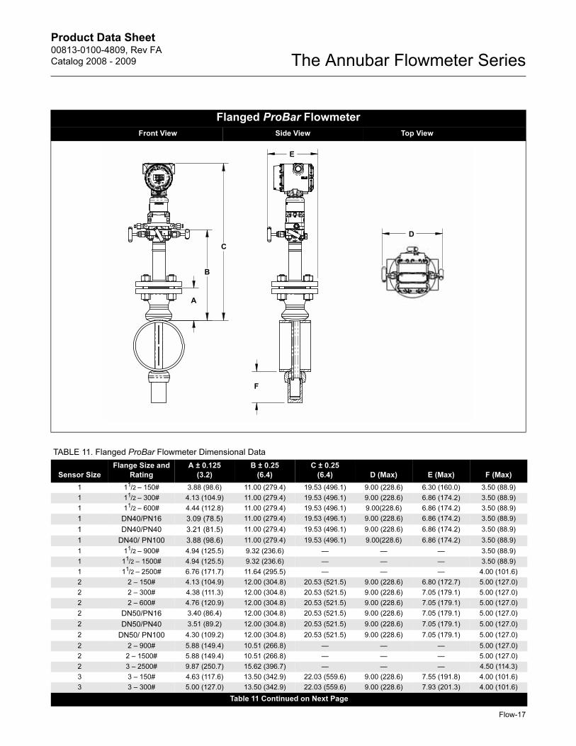
Flanged ProBar Flowmeter
__________Front View Side View Top View_____________
B
A
D
C
E
F
TABLE 11. Flanged ProBar Flowmeter Dimensional Data
Sensor Size
Flange Size and
Rating
A ± 0.125
(3.2)
B ± 0.25
(6.4)
C ± 0.25
(6.4) D (Max) E (Max) F (Max)
1 11/2 – 150# 3.88 (98.6) 11.00 (279.4) 19.53 (496.1) 9.00 (228.6) 6.30 (160.0) 3.50 (88.9)
1 11/2 – 300# 4.13 (104.9) 11.00 (279.4) 19.53 (496.1) 9.00 (228.6) 6.86 (174.2) 3.50 (88.9)
1 11/2 – 600# 4.44 (112.8) 11.00 (279.4) 19.53 (496.1) 9.00(228.6) 6.86 (174.2) 3.50 (88.9)
1 DN40/PN16 3.09 (78.5) 11.00 (279.4) 19.53 (496.1) 9.00 (228.6) 6.86 (174.2) 3.50 (88.9)
1 DN40/PN40 3.21 (81.5) 11.00 (279.4) 19.53 (496.1) 9.00 (228.6) 6.86 (174.2) 3.50 (88.9)
1 DN40/ PN100 3.88 (98.6) 11.00 (279.4) 19.53 (496.1) 9.00(228.6) 6.86 (174.2) 3.50 (88.9)
1 11/2 – 900# 4.94 (125.5) 9.32 (236.6) — — — 3.50 (88.9)
1 11/2 – 1500# 4.94 (125.5) 9.32 (236.6) — — — 3.50 (88.9)
1 11/2 – 2500# 6.76 (171.7) 11.64 (295.5) — — — 4.00 (101.6)
2 2 – 150# 4.13 (104.9) 12.00 (304.8) 20.53 (521.5) 9.00 (228.6) 6.80 (172.7) 5.00 (127.0)
2 2 – 300# 4.38 (111.3) 12.00 (304.8) 20.53 (521.5) 9.00 (228.6) 7.05 (179.1) 5.00 (127.0)
2 2 – 600# 4.76 (120.9) 12.00 (304.8) 20.53 (521.5) 9.00 (228.6) 7.05 (179.1) 5.00 (127.0)
2 DN50/PN16 3.40 (86.4) 12.00 (304.8) 20.53 (521.5) 9.00 (228.6) 7.05 (179.1) 5.00 (127.0)
2 DN50/PN40 3.51 (89.2) 12.00 (304.8) 20.53 (521.5) 9.00 (228.6) 7.05 (179.1) 5.00 (127.0)
2 DN50/ PN100 4.30 (109.2) 12.00 (304.8) 20.53 (521.5) 9.00 (228.6) 7.05 (179.1) 5.00 (127.0)
2 2 – 900# 5.88 (149.4) 10.51 (266.8) — — — 5.00 (127.0)
2 2 – 1500# 5.88 (149.4) 10.51 (266.8) — — — 5.00 (127.0)
2 3 – 2500# 9.87 (250.7) 15.62 (396.7) — — — 4.50 (114.3)
3 3 – 150# 4.63 (117.6) 13.50 (342.9) 22.03 (559.6) 9.00 (228.6) 7.55 (191.8) 4.00 (101.6)
3 3 – 300# 5.00 (127.0) 13.50 (342.9) 22.03 (559.6) 9.00 (228.6) 7.93 (201.3) 4.00 (101.6)
Table 11 Continued on Next Page

Product Data Sheet00813-0100-4809, Rev FA
Catalog 2008 - 2009The Annubar Flowmeter Series
Flow-18
3 3 – 600# 5.38 (136.7) 13.50 (342.9) 22.03 (559.6) 9.00 (228.6) 7.93 (201.3) 4.00 (101.6)
3 DN80/PN16 3.84 (97.5) 13.50 (342.9) 22.03 (559.6) 9.00 (228.6) 7.93 (201.3) 4.00 (101.6)
3 DN80/PN40 4.16 (105.7) 13.50 (342.9) 22.03 (559.6) 9.00 (228.6) 7.93 (201.3) 4.00 (101.6)
3 DN80/ PN100 4.95 (125.7) 13.50 (342.9) 22.03 (559.6) 9.00 (228.6) 7.93 (201.3) 4.00 (101.6)
3 4 – 900# 8.19 (208.0) 13.44 (341.3) — — — 7.00 (177.8)
3 4 – 1500# 8.56 (217.4) 13.81 (350.8) — — — 7.00 (177.8)
3 4 – 2500# 11.19 (284.2) 17.32 (439.8) — — — 7.00 (177.8)
Dimensions are in inches (millimeters)
TABLE 11. Flanged ProBar Flowmeter Dimensional Data
Sensor Size
Flange Size and
Rating
A ± 0.125
(3.2)
B ± 0.25
(6.4)
C ± 0.25
(6.4) D (Max) E (Max) F (Max)
Product Data Sheet00813-0100-4809, Rev FA
Catalog 2008 - 2009 The Annubar Flowmeter Series
Flow-19
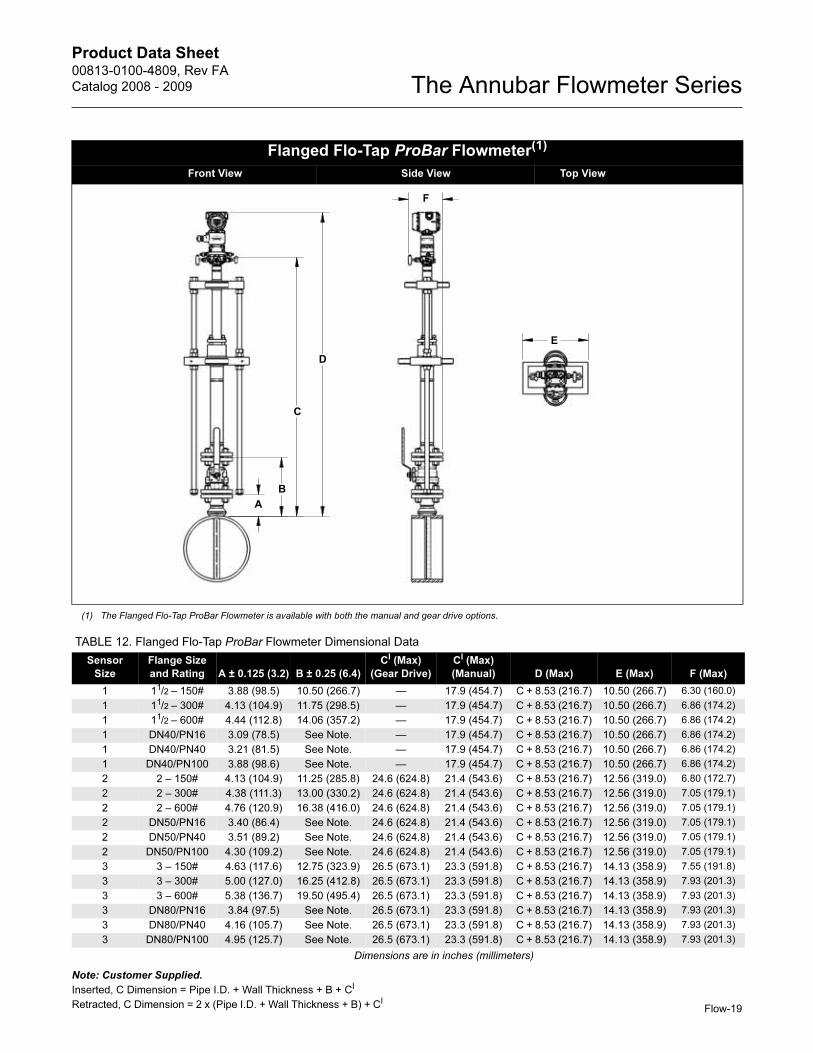
Note: Customer Supplied.
Inserted, C Dimension = Pipe I.D. + Wall Thickness + B + CI
Retracted, C Dimension = 2 x (Pipe I.D. + Wall Thickness + B) + CI
Flanged Flo-Tap ProBar Flowmeter(1)
_______Front View Side View Top View___________________
(1) The Flanged Flo-Tap ProBar Flowmeter is available with both the manual and gear drive options.
B
A
D
C
E
F
TABLE 12. Flanged Flo-Tap ProBar Flowmeter Dimensional Data
Sensor
Size
Flange Size
and Rating A ± 0.125 (3.2) B ± 0.25 (6.4)
CI (Max)
(Gear Drive)
CI (Max)
(Manual) D (Max) E (Max) F (Max)
1 11/2 – 150# 3.88 (98.5) 10.50 (266.7) — 17.9 (454.7) C + 8.53 (216.7) 10.50 (266.7) 6.30 (160.0)
1 11/2 – 300# 4.13 (104.9) 11.75 (298.5) — 17.9 (454.7) C + 8.53 (216.7) 10.50 (266.7) 6.86 (174.2)
1 11/2 – 600# 4.44 (112.8) 14.06 (357.2) — 17.9 (454.7) C + 8.53 (216.7) 10.50 (266.7) 6.86 (174.2)
1 DN40/PN16 3.09 (78.5) See Note. — 17.9 (454.7) C + 8.53 (216.7) 10.50 (266.7) 6.86 (174.2)
1 DN40/PN40 3.21 (81.5) See Note. — 17.9 (454.7) C + 8.53 (216.7) 10.50 (266.7) 6.86 (174.2)
1 DN40/PN100 3.88 (98.6) See Note. — 17.9 (454.7) C + 8.53 (216.7) 10.50 (266.7) 6.86 (174.2)
2 2 – 150# 4.13 (104.9) 11.25 (285.8) 24.6 (624.8) 21.4 (543.6) C + 8.53 (216.7) 12.56 (319.0) 6.80 (172.7)
2 2 – 300# 4.38 (111.3) 13.00 (330.2) 24.6 (624.8) 21.4 (543.6) C + 8.53 (216.7) 12.56 (319.0) 7.05 (179.1)
2 2 – 600# 4.76 (120.9) 16.38 (416.0) 24.6 (624.8) 21.4 (543.6) C + 8.53 (216.7) 12.56 (319.0) 7.05 (179.1)
2 DN50/PN16 3.40 (86.4) See Note. 24.6 (624.8) 21.4 (543.6) C + 8.53 (216.7) 12.56 (319.0) 7.05 (179.1)
2 DN50/PN40 3.51 (89.2) See Note. 24.6 (624.8) 21.4 (543.6) C + 8.53 (216.7) 12.56 (319.0) 7.05 (179.1)
2 DN50/PN100 4.30 (109.2) See Note. 24.6 (624.8) 21.4 (543.6) C + 8.53 (216.7) 12.56 (319.0) 7.05 (179.1)
3 3 – 150# 4.63 (117.6) 12.75 (323.9) 26.5 (673.1) 23.3 (591.8) C + 8.53 (216.7) 14.13 (358.9) 7.55 (191.8)
3 3 – 300# 5.00 (127.0) 16.25 (412.8) 26.5 (673.1) 23.3 (591.8) C + 8.53 (216.7) 14.13 (358.9) 7.93 (201.3)
3 3 – 600# 5.38 (136.7) 19.50 (495.4) 26.5 (673.1) 23.3 (591.8) C + 8.53 (216.7) 14.13 (358.9) 7.93 (201.3)
3 DN80/PN16 3.84 (97.5) See Note. 26.5 (673.1) 23.3 (591.8) C + 8.53 (216.7) 14.13 (358.9) 7.93 (201.3)
3 DN80/PN40 4.16 (105.7) See Note. 26.5 (673.1) 23.3 (591.8) C + 8.53 (216.7) 14.13 (358.9) 7.93 (201.3)
3 DN80/PN100 4.95 (125.7) See Note. 26.5 (673.1) 23.3 (591.8) C + 8.53 (216.7) 14.13 (358.9) 7.93 (201.3)
Dimensions are in inches (millimeters)
Product Data Sheet00813-0100-4809, Rev FA
Catalog 2008 - 2009The Annubar Flowmeter Series
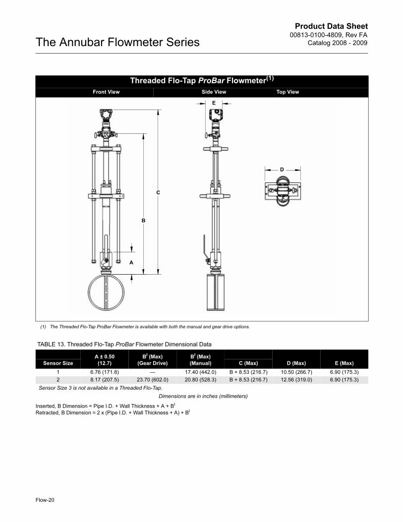
Inserted, B Dimension = Pipe I.D. + Wall Thickness + A + BI
Retracted, B Dimension = 2 x (Pipe I.D. + Wall Thickness + A) + BI
Threaded Flo-Tap ProBar Flowmeter(1)
________Front View Side View Top View_______________________
(1) The Threaded Flo-Tap ProBar Flowmeter is available with both the manual and gear drive options.
B
A
D
C
E
TABLE 13. Threaded Flo-Tap ProBar Flowmeter Dimensional Data
A ± 0.50
(12.7)
BI (Max)
(Gear Drive)
BI (Max)
(Manual) D (Max) E (Max)Sensor Size C (Max)
1 6.76 (171.8) — 17.40 (442.0) B + 8.53 (216.7) 10.50 (266.7) 6.90 (175.3)
2 8.17 (207.5) 23.70 (602.0) 20.80 (528.3) B + 8.53 (216.7) 12.56 (319.0) 6.90 (175.3)
Sensor Size 3 is not available in a Threaded Flo-Tap.
Dimensions are in inches (millimeters)
Flow-20
Product Data Sheet00813-0100-4809, Rev FA
Catalog 2008 - 2009 The Annubar Flowmeter Series
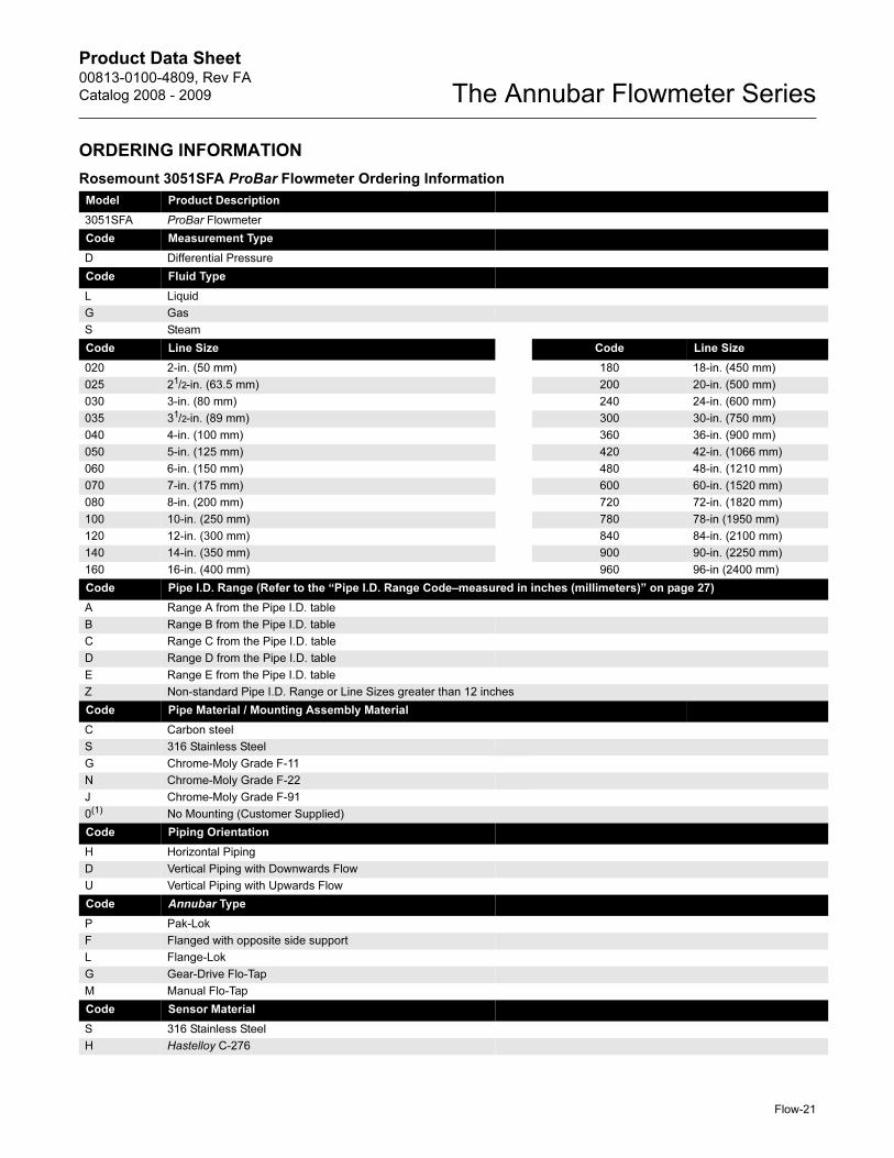
ORDERING INFORMATION
Rosemount 3051SFA ProBar Flowmeter Ordering Information
Model Product Description
3051SFA ProBar Flowmeter
Code Measurement Type
D Differential Pressure
Code Fluid Type
L Liquid
G Gas
S Steam
Code Line Size Code Line Size
020 2-in. (50 mm) 180 18-in. (450 mm)
025 21/2-in. (63.5 mm) 200 20-in. (500 mm)
030 3-in. (80 mm) 240 24-in. (600 mm)
035 31/2-in. (89 mm) 300 30-in. (750 mm)
040 4-in. (100 mm) 360 36-in. (900 mm)
050 5-in. (125 mm) 420 42-in. (1066 mm)
060 6-in. (150 mm) 480 48-in. (1210 mm)
070 7-in. (175 mm) 600 60-in. (1520 mm)
080 8-in. (200 mm) 720 72-in. (1820 mm)
100 10-in. (250 mm) 780 78-in (1950 mm)
120 12-in. (300 mm) 840 84-in. (2100 mm)
140 14-in. (350 mm) 900 90-in. (2250 mm)
160 16-in. (400 mm) 960 96-in (2400 mm)
Code Pipe I.D. Range (Refer to the “Pipe I.D. Range Code–measured in inches (millimeters)” on page 27)
A Range A from the Pipe I.D. table
B Range B from the Pipe I.D. table
C Range C from the Pipe I.D. table
D Range D from the Pipe I.D. table
E Range E from the Pipe I.D. table
Z Non-standard Pipe I.D. Range or Line Sizes greater than 12 inches
Code Pipe Material / Mounting Assembly Material
C Carbon steel
S 316 Stainless Steel
G Chrome-Moly Grade F-11
N Chrome-Moly Grade F-22
J Chrome-Moly Grade F-91
0(1) No Mounting (Customer Supplied)
Code Piping Orientation
H Horizontal Piping
D Vertical Piping with Downwards Flow
U Vertical Piping with Upwards Flow
Code Annubar Type
P Pak-Lok
F Flanged with opposite side support
L Flange-Lok
G Gear-Drive Flo-Tap
M Manual Flo-Tap
Code Sensor Material
S 316 Stainless Steel
H Hastelloy C-276
Flow-21
Product Data Sheet00813-0100-4809, Rev FA
Catalog 2008 - 2009The Annubar Flowmeter Series
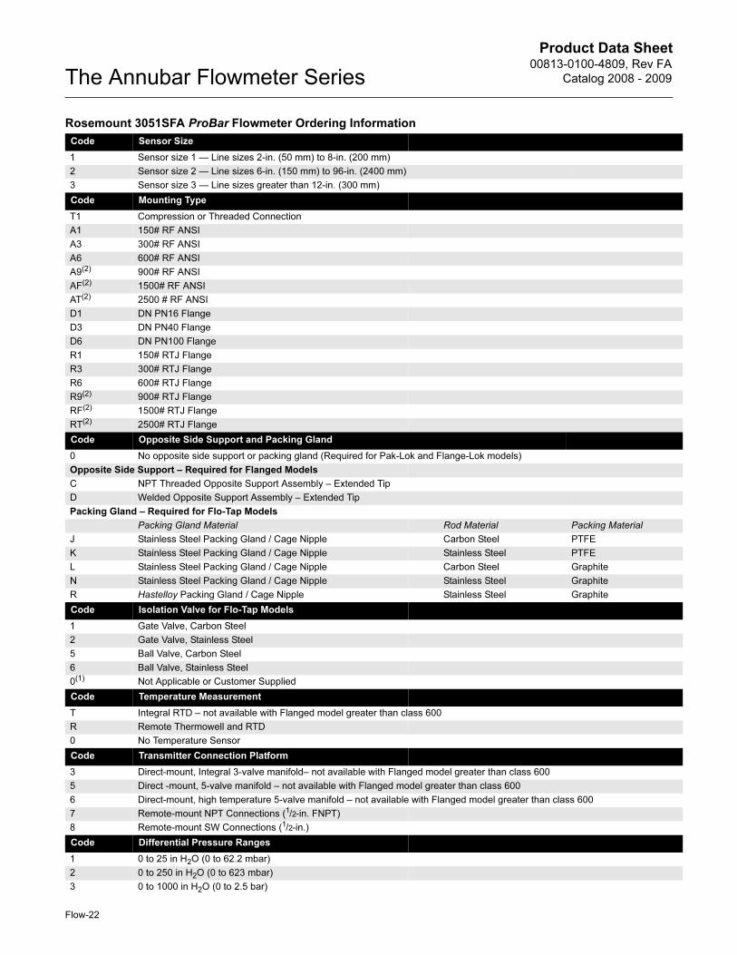
Code Sensor Size
1 Sensor size 1 — Line sizes 2-in. (50 mm) to 8-in. (200 mm)
2 Sensor size 2 — Line sizes 6-in. (150 mm) to 96-in. (2400 mm)
3 Sensor size 3 — Line sizes greater than 12-in. (300 mm)
Code Mounting Type
T1 Compression or Threaded Connection
A1 150# RF ANSI
A3 300# RF ANSI
A6 600# RF ANSI
A9(2) 900# RF ANSI
AF(2) 1500# RF ANSI
AT(2) 2500 # RF ANSI
D1 DN PN16 Flange
D3 DN PN40 Flange
D6 DN PN100 Flange
R1 150# RTJ Flange
R3 300# RTJ Flange
R6 600# RTJ Flange
R9(2) 900# RTJ Flange
RF(2) 1500# RTJ Flange
RT(2) 2500# RTJ Flange
Code Opposite Side Support and Packing Gland
0 No opposite side support or packing gland (Required for Pak-Lok and Flange-Lok models)
Opposite Side Support – Required for Flanged Models
C NPT Threaded Opposite Support Assembly – Extended Tip
D Welded Opposite Support Assembly – Extended Tip
Packing Gland – Required for Flo-Tap Models
Packing Gland Material Rod Material Packing Material
J Stainless Steel Packing Gland / Cage Nipple Carbon Steel PTFE
K Stainless Steel Packing Gland / Cage Nipple Stainless Steel PTFE
L Stainless Steel Packing Gland / Cage Nipple Carbon Steel Graphite
N Stainless Steel Packing Gland / Cage Nipple Stainless Steel Graphite
R Hastelloy Packing Gland / Cage Nipple Stainless Steel Graphite
Code Isolation Valve for Flo-Tap Models
1 Gate Valve, Carbon Steel
2 Gate Valve, Stainless Steel
5 Ball Valve, Carbon Steel
6 Ball Valve, Stainless Steel
0(1) Not Applicable or Customer Supplied
Code Temperature Measurement
T Integral RTD – not available with Flanged model greater than class 600
R Remote Thermowell and RTD
0 No Temperature Sensor
Code Transmitter Connection Platform
3 Direct-mount, Integral 3-valve manifold– not available with Flanged model greater than class 600
5 Direct -mount, 5-valve manifold – not available with Flanged model greater than class 600
6 Direct-mount, high temperature 5-valve manifold – not available with Flanged model greater than class 600
7 Remote-mount NPT Connections (1/2-in. FNPT)
8 Remote-mount SW Connections (1/2-in.)
Code Differential Pressure Ranges
1 0 to 25 in H2O (0 to 62.2 mbar)
2 0 to 250 in H2O (0 to 623 mbar)
3 0 to 1000 in H2O (0 to 2.5 bar)
Rosemount 3051SFA ProBar Flowmeter Ordering Information
Flow-22
Product Data Sheet00813-0100-4809, Rev FA
Catalog 2008 - 2009 The Annubar Flowmeter Series
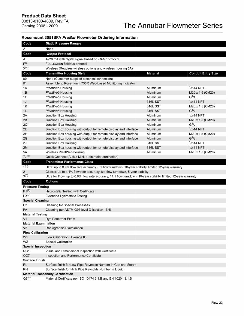
Code Static Pressure Ranges
A None
Code Output Protocol
A 4–20 mA with digital signal based on HART protocol
F(3) FOUNDATION fieldbus protocol
X(4) Wireless (Requires wireless options and wireless housing 5A)
Code Transmitter Housing Style Material Conduit Entry Size
00 None (Customer-supplied electrical connection)
01 Assemble to Rosemount 753R Web-based Monitoring Indicator
1A PlantWeb Housing Aluminum 1/2-14 NPT
1B PlantWeb Housing Aluminum M20 x 1.5 (CM20)
1C PlantWeb Housing Aluminum G1/2
1J PlantWeb Housing 316L SST 1/2-14 NPT
1K PlantWeb Housing 316L SST M20 x 1.5 (CM20)
1L PlantWeb Housing 316L SST G1/2
2A Junction Box Housing Aluminum 1/2-14 NPT
2B Junction Box Housing Aluminum M20 x 1.5 (CM20)
2C Junction Box Housing Aluminum G1/2
2E Junction Box housing with output for remote display and interface Aluminum 1/2-14 NPT
2F Junction Box housing with output for remote display and interface Aluminum M20 x 1.5 (CM20)
2G Junction Box housing with output for remote display and interface Aluminum G1/2
2J Junction Box Housing 316L SST 1/2-14 NPT
2M Junction Box housing with output for remote display and interface 316L SST 1/2-14 NPT
5A Wireless PlantWeb housing Aluminum M20 x 1.5 (CM20)
7J(5) Quick Connect (A size Mini, 4-pin male termination)
Code Transmitter Performance Class
1(6) Ultra: up to 0.9% flow rate accuracy, 8:1 flow turndown, 10-year stability, limited 12-year warranty
2 Classic: up to 1.1% flow rate accuracy, 8:1 flow turndown, 5-year stability
3(6) Ultra for Flow: up to 0.8% flow rate accuracy, 14:1 flow turndown, 10-year stability. limited 12-year warranty
Code Options
Pressure Testing
P1(7) Hydrostatic Testing with Certificate
PX(7) Extended Hydrostatic Testing
Special Cleaning
P2 Cleaning for Special Processes
PA Cleaning per ASTM G93 level D (section 11.4)
Material Testing
V1 Dye Penetrant Exam
Material Examination
V2 Radiographic Examination
Flow Calibration
W1 Flow Calibration (Average K)
WZ Special Calibration
Special Inspection
QC1 Visual and Dimensional Inspection with Certificate
QC7 Inspection and Performance Certificate
Surface Finish
RL Surface finish for Low Pipe Reynolds Number in Gas and Steam
RH Surface finish for High Pipe Reynolds Number in Liquid
Material Traceability Certification
Q8(8) Material Certificate per ISO 10474 3.1.B and EN 10204 3.1.B
Rosemount 3051SFA ProBar Flowmeter Ordering Information
Flow-23
Product Data Sheet00813-0100-4809, Rev FA
Catalog 2008 - 2009The Annubar Flowmeter Series
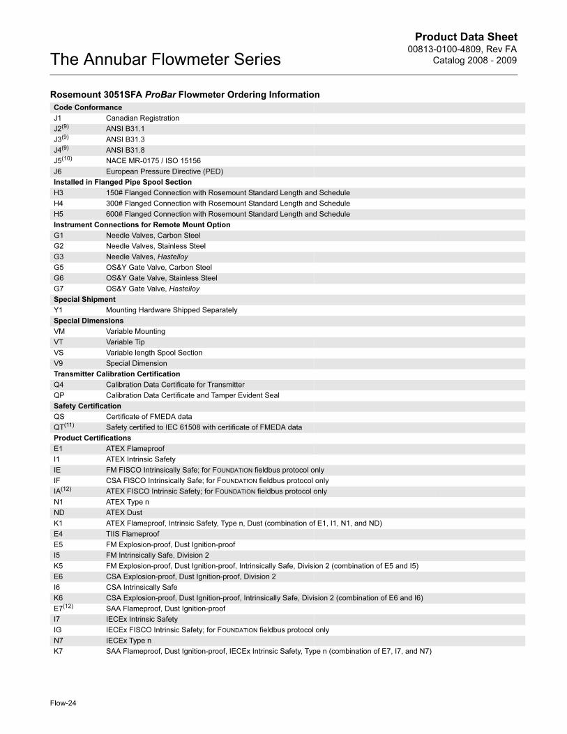
Code Conformance
J1 Canadian Registration
J2(9) ANSI B31.1
J3(9) ANSI B31.3
J4(9) ANSI B31.8
J5(10) NACE MR-0175 / ISO 15156
J6 European Pressure Directive (PED)
Installed in Flanged Pipe Spool Section
H3 150# Flanged Connection with Rosemount Standard Length and Schedule
H4 300# Flanged Connection with Rosemount Standard Length and Schedule
H5 600# Flanged Connection with Rosemount Standard Length and Schedule
Instrument Connections for Remote Mount Option
G1 Needle Valves, Carbon Steel
G2 Needle Valves, Stainless Steel
G3 Needle Valves, Hastelloy
G5 OS&Y Gate Valve, Carbon Steel
G6 OS&Y Gate Valve, Stainless Steel
G7 OS&Y Gate Valve, Hastelloy
Special Shipment
Y1 Mounting Hardware Shipped Separately
Special Dimensions
VM Variable Mounting
VT Variable Tip
VS Variable length Spool Section
V9 Special Dimension
Transmitter Calibration Certification
Q4 Calibration Data Certificate for Transmitter
QP Calibration Data Certificate and Tamper Evident Seal
Safety Certification
QS Certificate of FMEDA data
QT(11) Safety certified to IEC 61508 with certificate of FMEDA data
Product Certifications
E1 ATEX Flameproof
I1 ATEX Intrinsic Safety
IE FM FISCO Intrinsically Safe; for FOUNDATION fieldbus protocol only
IF CSA FISCO Intrinsically Safe; for FOUNDATION fieldbus protocol only
IA(12) ATEX FISCO Intrinsic Safety; for FOUNDATION fieldbus protocol only
N1 ATEX Type n
ND ATEX Dust
K1 ATEX Flameproof, Intrinsic Safety, Type n, Dust (combination of E1, I1, N1, and ND)
E4 TIIS Flameproof
E5 FM Explosion-proof, Dust Ignition-proof
I5 FM Intrinsically Safe, Division 2
K5 FM Explosion-proof, Dust Ignition-proof, Intrinsically Safe, Division 2 (combination of E5 and I5)
E6 CSA Explosion-proof, Dust Ignition-proof, Division 2
I6 CSA Intrinsically Safe
K6 CSA Explosion-proof, Dust Ignition-proof, Intrinsically Safe, Division 2 (combination of E6 and I6)
E7(12) SAA Flameproof, Dust Ignition-proof
I7 IECEx Intrinsic Safety
IG IECEx FISCO Intrinsic Safety; for FOUNDATION fieldbus protocol only
N7 IECEx Type n
K7 SAA Flameproof, Dust Ignition-proof, IECEx Intrinsic Safety, Type n (combination of E7, I7, and N7)
Rosemount 3051SFA ProBar Flowmeter Ordering Information
Flow-24
Product Data Sheet00813-0100-4809, Rev FA
Catalog 2008 - 2009 The Annubar Flowmeter Series
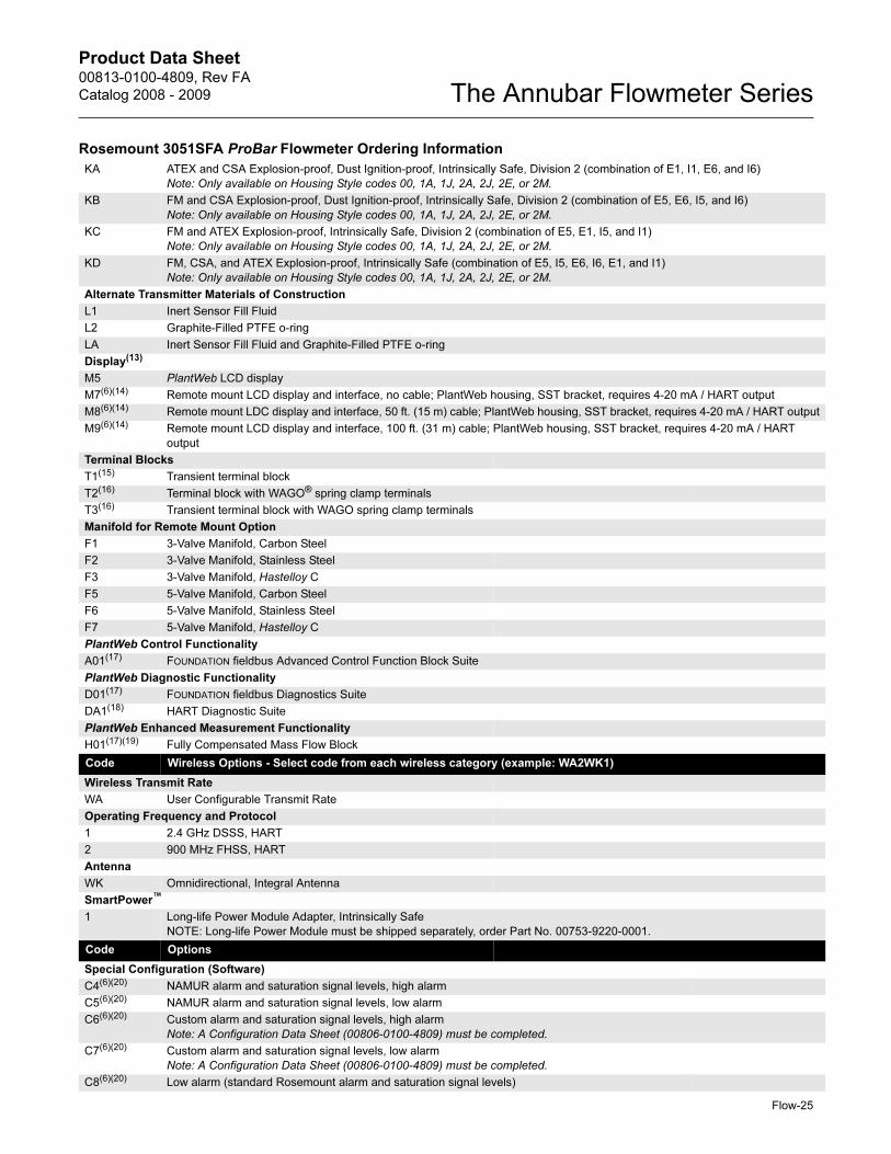
KA ATEX and CSA Explosion-proof, Dust Ignition-proof, Intrinsically Safe, Division 2 (combination of E1, I1, E6, and I6)
Note: Only available on Housing Style codes 00, 1A, 1J, 2A, 2J, 2E, or 2M.
KB FM and CSA Explosion-proof, Dust Ignition-proof, Intrinsically Safe, Division 2 (combination of E5, E6, I5, and I6)
Note: Only available on Housing Style codes 00, 1A, 1J, 2A, 2J, 2E, or 2M.
KC FM and ATEX Explosion-proof, Intrinsically Safe, Division 2 (combination of E5, E1, I5, and I1)
Note: Only available on Housing Style codes 00, 1A, 1J, 2A, 2J, 2E, or 2M.
KD FM, CSA, and ATEX Explosion-proof, Intrinsically Safe (combination of E5, I5, E6, I6, E1, and I1)
Note: Only available on Housing Style codes 00, 1A, 1J, 2A, 2J, 2E, or 2M.
Alternate Transmitter Materials of Construction
L1 Inert Sensor Fill Fluid
L2 Graphite-Filled PTFE o-ring
LA Inert Sensor Fill Fluid and Graphite-Filled PTFE o-ring
Display(13)
M5 PlantWeb LCD display
M7(6)(14) Remote mount LCD display and interface, no cable; PlantWeb housing, SST bracket, requires 4-20 mA / HART output
M8(6)(14) Remote mount LDC display and interface, 50 ft. (15 m) cable; PlantWeb housing, SST bracket, requires 4-20 mA / HART output
M9(6)(14) Remote mount LCD display and interface, 100 ft. (31 m) cable; PlantWeb housing, SST bracket, requires 4-20 mA / HART
output
Terminal Blocks
T1(15) Transient terminal block
T2(16) Terminal block with WAGO® spring clamp terminals
T3(16) Transient terminal block with WAGO spring clamp terminals
Manifold for Remote Mount Option
F1 3-Valve Manifold, Carbon Steel
F2 3-Valve Manifold, Stainless Steel
F3 3-Valve Manifold, Hastelloy C
F5 5-Valve Manifold, Carbon Steel
F6 5-Valve Manifold, Stainless Steel
F7 5-Valve Manifold, Hastelloy C
PlantWeb Control Functionality
A01(17) FOUNDATION fieldbus Advanced Control Function Block Suite
PlantWeb Diagnostic Functionality
D01(17) FOUNDATION fieldbus Diagnostics Suite
DA1(18) HART Diagnostic Suite
PlantWeb Enhanced Measurement Functionality
H01(17)(19) Fully Compensated Mass Flow Block
Code Wireless Options - Select code from each wireless category (example: WA2WK1)
Wireless Transmit Rate
WA User Configurable Transmit Rate
Operating Frequency and Protocol
1 2.4 GHz DSSS, HART
2 900 MHz FHSS, HART
Antenna
WK Omnidirectional, Integral Antenna
SmartPower™
1 Long-life Power Module Adapter, Intrinsically Safe
NOTE: Long-life Power Module must be shipped separately, order Part No. 00753-9220-0001.
Code Options
Special Configuration (Software)
C4(6)(20) NAMUR alarm and saturation signal levels, high alarm
C5(6)(20) NAMUR alarm and saturation signal levels, low alarm
C6(6)(20) Custom alarm and saturation signal levels, high alarm
Note: A Configuration Data Sheet (00806-0100-4809) must be completed.
C7(6)(20) Custom alarm and saturation signal levels, low alarm
Note: A Configuration Data Sheet (00806-0100-4809) must be completed.
C8(6)(20) Low alarm (standard Rosemount alarm and saturation signal levels)
Rosemount 3051SFA ProBar Flowmeter Ordering Information
Flow-25
Product Data Sheet00813-0100-4809, Rev FA
Catalog 2008 - 2009The Annubar Flowmeter Series
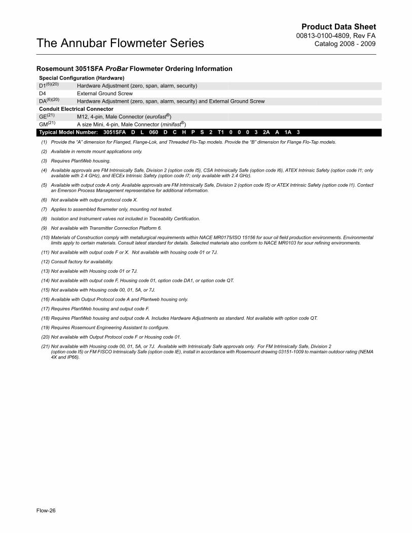
Special Configuration (Hardware)
D1(6)(20) Hardware Adjustment (zero, span, alarm, security)
D4 External Ground Screw
DA(6)(20) Hardware Adjustment (zero, span, alarm, security) and External Ground Screw
Conduit Electrical Connector
GE(21) M12, 4-pin, Male Connector (eurofast®)
GM(21) A size Mini, 4-pin, Male Connector (minifast®)
Typical Model Number: 3051SFA D L 060 D C H P S 2 T1 0 0 0 3 2A A 1A 3
(1) Provide the “A” dimension for Flanged, Flange-Lok, and Threaded Flo-Tap models. Provide the “B” dimension for Flange Flo-Tap models.
(2) Available in remote mount applications only.
(3) Requires PlantWeb housing.
(4) Available approvals are FM Intrinsically Safe, Division 2 (option code I5), CSA Intrinsically Safe (option code I6), ATEX Intrinsic Safety (option code I1; only available with 2.4 GHz), and IECEx Intrinsic Safety (option code I7; only available with 2.4 GHz).
(5) Available with output code A only. Available approvals are FM Intrinsically Safe, Division 2 (option code I5) or ATEX Intrinsic Safety (option code I1). Contact an Emerson Process Management representative for additional information.
(6) Not available with output protocol code X.
(7) Applies to assembled flowmeter only, mounting not tested.
(8) Isolation and Instrument valves not included in Traceability Certification.
(9) Not available with Transmitter Connection Platform 6.
(10) Materials of Construction comply with metallurgical requirements within NACE MR0175/ISO 15156 for sour oil field production environments. Environmental limits apply to certain materials. Consult latest standard for details. Selected materials also conform to NACE MR0103 for sour refining environments.
(11) Not available with output code F or X. Not available with housing code 01 or 7J.
(12) Consult factory for availability.
(13) Not available with Housing code 01 or 7J.
(14) Not available with output code F, Housing code 01, option code DA1, or option code QT.
(15) Not available with Housing code 00, 01, 5A, or 7J.
(16) Available with Output Protocol code A and Plantweb housing only.
(17) Requires PlantWeb housing and output code F.
(18) Requires PlantWeb housing and output code A. Includes Hardware Adjustments as standard. Not available with option code QT.
(19) Requires Rosemount Engineering Assistant to configure.
(20) Not available with Output Protocol code F or Housing code 01.
(21) Not available with Housing code 00, 01, 5A, or 7J. Available with Intrinsically Safe approvals only. For FM Intrinsically Safe, Division 2(option code I5) or FM FISCO Intrinsically Safe (option code IE), install in accordance with Rosemount drawing 03151-1009 to maintain outdoor rating (NEMA 4X and IP66).
Rosemount 3051SFA ProBar Flowmeter Ordering Information
Flow-26
Product Data Sheet00813-0100-4809, Rev FA
Catalog 2008 - 2009 The Annubar Flowmeter Series
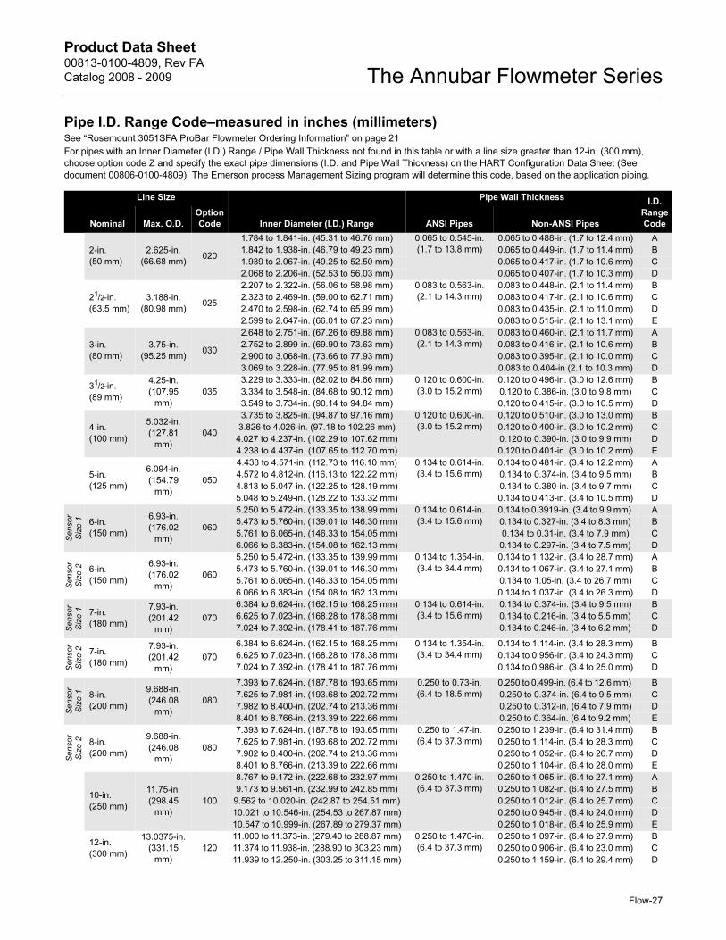
Pipe I.D. Range Code–measured in inches (millimeters)See “Rosemount 3051SFA ProBar Flowmeter Ordering Information” on page 21
For pipes with an Inner Diameter (I.D.) Range / Pipe Wall Thickness not found in this table or with a line size greater than 12-in. (300 mm),
choose option code Z and specify the exact pipe dimensions (I.D. and Pipe Wall Thickness) on the HART Configuration Data Sheet (See
document 00806-0100-4809). The Emerson process Management Sizing program will determine this code, based on the application piping.
Line Size
Inner Diameter (I.D.) Range
Pipe Wall Thickness I.D.
Range
CodeNominal Max. O.D.
Option
Code ANSI Pipes Non-ANSI Pipes
2-in.
(50 mm)
2.625-in.
(66.68 mm)020
1.784 to 1.841-in. (45.31 to 46.76 mm) 0.065 to 0.545-in.
(1.7 to 13.8 mm)
0.065 to 0.488-in. (1.7 to 12.4 mm) A
1.842 to 1.938-in. (46.79 to 49.23 mm) 0.065 to 0.449-in. (1.7 to 11.4 mm) B
1.939 to 2.067-in. (49.25 to 52.50 mm) 0.065 to 0.417-in. (1.7 to 10.6 mm) C
2.068 to 2.206-in. (52.53 to 56.03 mm) 0.065 to 0.407-in. (1.7 to 10.3 mm) D
21/2-in.
(63.5 mm)
3.188-in.
(80.98 mm)025
2.207 to 2.322-in. (56.06 to 58.98 mm) 0.083 to 0.563-in.
(2.1 to 14.3 mm)
0.083 to 0.448-in. (2.1 to 11.4 mm) B
2.323 to 2.469-in. (59.00 to 62.71 mm) 0.083 to 0.417-in. (2.1 to 10.6 mm) C
2.470 to 2.598-in. (62.74 to 65.99 mm) 0.083 to 0.435-in. (2.1 to 11.0 mm) D
2.599 to 2.647-in. (66.01 to 67.23 mm) 0.083 to 0.515-in. (2.1 to 13.1 mm) E
3-in.
(80 mm)
3.75-in.
(95.25 mm)030
2.648 to 2.751-in. (67.26 to 69.88 mm) 0.083 to 0.563-in.
(2.1 to 14.3 mm)
0.083 to 0.460-in. (2.1 to 11.7 mm) A
2.752 to 2.899-in. (69.90 to 73.63 mm) 0.083 to 0.416-in. (2.1 to 10.6 mm) B
2.900 to 3.068-in. (73.66 to 77.93 mm) 0.083 to 0.395-in. (2.1 to 10.0 mm) C
3.069 to 3.228-in. (77.95 to 81.99 mm) 0.083 to 0.404-in (2.1 to 10.3 mm) D
31/2-in.
(89 mm)
4.25-in.
(107.95
mm)
035
3.229 to 3.333-in. (82.02 to 84.66 mm) 0.120 to 0.600-in.
(3.0 to 15.2 mm)
0.120 to 0.496-in. (3.0 to 12.6 mm) B
3.334 to 3.548-in. (84.68 to 90.12 mm) 0.120 to 0.386-in. (3.0 to 9.8 mm) C
3.549 to 3.734-in. (90.14 to 94.84 mm) 0.120 to 0.415-in. (3.0 to 10.5 mm) D
4-in.
(100 mm)
5.032-in.
(127.81
mm)
040
3.735 to 3.825-in. (94.87 to 97.16 mm) 0.120 to 0.600-in.
(3.0 to 15.2 mm)
0.120 to 0.510-in. (3.0 to 13.0 mm) B
3.826 to 4.026-in. (97.18 to 102.26 mm) 0.120 to 0.400-in. (3.0 to 10.2 mm) C
4.027 to 4.237-in. (102.29 to 107.62 mm) 0.120 to 0.390-in. (3.0 to 9.9 mm) D
4.238 to 4.437-in. (107.65 to 112.70 mm) 0.120 to 0.401-in. (3.0 to 10.2 mm) E
5-in.
(125 mm)
6.094-in.
(154.79
mm)
050
4.438 to 4.571-in. (112.73 to 116.10 mm) 0.134 to 0.614-in.
(3.4 to 15.6 mm)
0.134 to 0.481-in. (3.4 to 12.2 mm) A
4.572 to 4.812-in. (116.13 to 122.22 mm) 0.134 to 0.374-in. (3.4 to 9.5 mm) B
4.813 to 5.047-in. (122.25 to 128.19 mm) 0.134 to 0.380-in. (3.4 to 9.7 mm) C
5.048 to 5.249-in. (128.22 to 133.32 mm) 0.134 to 0.413-in. (3.4 to 10.5 mm) D
Sensor
Siz
e 1 6-in.
(150 mm)
6.93-in.
(176.02
mm)
060
5.250 to 5.472-in. (133.35 to 138.99 mm) 0.134 to 0.614-in.
(3.4 to 15.6 mm)
0.134 to 0.3919-in. (3.4 to 9.9 mm) A
5.473 to 5.760-in. (139.01 to 146.30 mm) 0.134 to 0.327-in. (3.4 to 8.3 mm) B
5.761 to 6.065-in. (146.33 to 154.05 mm) 0.134 to 0.31-in. (3.4 to 7.9 mm) C
6.066 to 6.383-in. (154.08 to 162.13 mm) 0.134 to 0.297-in. (3.4 to 7.5 mm) D
Sensor
Siz
e 2 6-in.
(150 mm)
6.93-in.
(176.02
mm)
060
5.250 to 5.472-in. (133.35 to 139.99 mm) 0.134 to 1.354-in.
(3.4 to 34.4 mm)
0.134 to 1.132-in. (3.4 to 28.7 mm) A
5.473 to 5.760-in. (139.01 to 146.30 mm) 0.134 to 1.067-in. (3.4 to 27.1 mm) B
5.761 to 6.065-in. (146.33 to 154.05 mm) 0.134 to 1.05-in. (3.4 to 26.7 mm) C
6.066 to 6.383-in. (154.08 to 162.13 mm) 0.134 to 1.037-in. (3.4 to 26.3 mm) D
Sensor
Siz
e 1 7-in.
(180 mm)
7.93-in.
(201.42
mm)
070
6.384 to 6.624-in. (162.15 to 168.25 mm) 0.134 to 0.614-in.
(3.4 to 15.6 mm)
0.134 to 0.374-in. (3.4 to 9.5 mm) B
6.625 to 7.023-in. (168.28 to 178.38 mm) 0.134 to 0.216-in. (3.4 to 5.5 mm) C
7.024 to 7.392-in. (178.41 to 187.76 mm) 0.134 to 0.246-in. (3.4 to 6.2 mm) D
Sensor
Siz
e 2 7-in.
(180 mm)
7.93-in.
(201.42
mm)
070
6.384 to 6.624-in. (162.15 to 168.25 mm) 0.134 to 1.354-in.
(3.4 to 34.4 mm)
0.134 to 1.114-in. (3.4 to 28.3 mm) B
6.625 to 7.023-in. (168.28 to 178.38 mm) 0.134 to 0.956-in. (3.4 to 24.3 mm) C
7.024 to 7.392-in. (178.41 to 187.76 mm) 0.134 to 0.986-in. (3.4 to 25.0 mm) D
Sensor
Siz
e 1 8-in.
(200 mm)
9.688-in.
(246.08
mm)
080
7.393 to 7.624-in. (187.78 to 193.65 mm) 0.250 to 0.73-in.
(6.4 to 18.5 mm)
0.250 to 0.499-in. (6.4 to 12.6 mm) B
7.625 to 7.981-in. (193.68 to 202.72 mm) 0.250 to 0.374-in. (6.4 to 9.5 mm) C
7.982 to 8.400-in. (202.74 to 213.36 mm) 0.250 to 0.312-in. (6.4 to 7.9 mm) D
8.401 to 8.766-in. (213.39 to 222.66 mm) 0.250 to 0.364-in. (6.4 to 9.2 mm) E
Sensor
Siz
e 2 8-in.
(200 mm)
9.688-in.
(246.08
mm)
080
7.393 to 7.624-in. (187.78 to 193.65 mm) 0.250 to 1.47-in.
(6.4 to 37.3 mm)
0.250 to 1.239-in. (6.4 to 31.4 mm) B
7.625 to 7.981-in. (193.68 to 202.72 mm) 0.250 to 1.114-in. (6.4 to 28.3 mm) C
7.982 to 8.400-in. (202.74 to 213.36 mm) 0.250 to 1.052-in. (6.4 to 26.7 mm) D
8.401 to 8.766-in. (213.39 to 222.66 mm) 0.250 to 1.104-in. (6.4 to 28.0 mm) E
10-in.
(250 mm)
11.75-in.
(298.45
mm)
100
8.767 to 9.172-in. (222.68 to 232.97 mm) 0.250 to 1.470-in.
(6.4 to 37.3 mm)
0.250 to 1.065-in. (6.4 to 27.1 mm) A
9.173 to 9.561-in. (232.99 to 242.85 mm) 0.250 to 1.082-in. (6.4 to 27.5 mm) B
9.562 to 10.020-in. (242.87 to 254.51 mm) 0.250 to 1.012-in. (6.4 to 25.7 mm) C
10.021 to 10.546-in. (254.53 to 267.87 mm) 0.250 to 0.945-in. (6.4 to 24.0 mm) D
10.547 to 10.999-in. (267.89 to 279.37 mm) 0.250 to 1.018-in. (6.4 to 25.9 mm) E
12-in.
(300 mm)
13.0375-in.
(331.15
mm)
120
11.000 to 11.373-in. (279.40 to 288.87 mm) 0.250 to 1.470-in.
(6.4 to 37.3 mm)
0.250 to 1.097-in. (6.4 to 27.9 mm) B
11.374 to 11.938-in. (288.90 to 303.23 mm) 0.250 to 0.906-in. (6.4 to 23.0 mm) C
11.939 to 12.250-in. (303.25 to 311.15 mm) 0.250 to 1.159-in. (6.4 to 29.4 mm) D
Flow-27
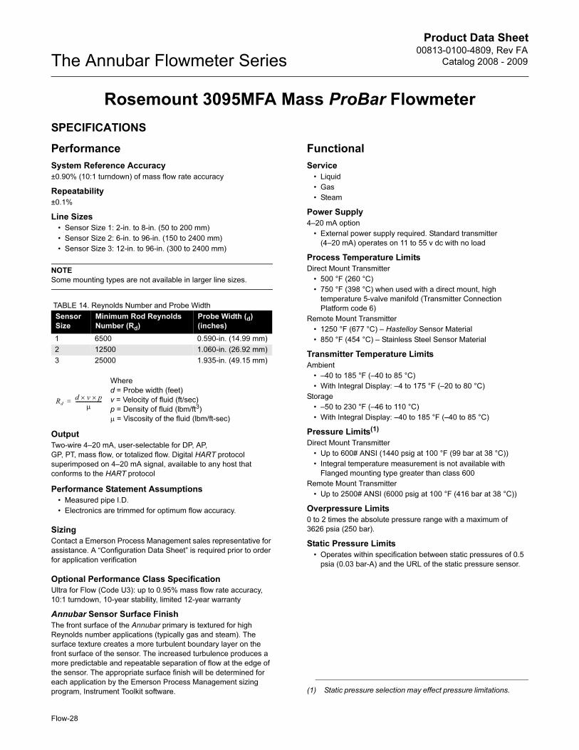
Product Data Sheet00813-0100-4809, Rev FA
Catalog 2008 - 2009The Annubar Flowmeter Series
Rosemount 3095MFA Mass ProBar Flowmeter
SPECIFICATIONS
Performance
System Reference Accuracy
±0.90% (10:1 turndown) of mass flow rate accuracy
Repeatability
±0.1%
Line Sizes
• Sensor Size 1: 2-in. to 8-in. (50 to 200 mm)
• Sensor Size 2: 6-in. to 96-in. (150 to 2400 mm)
• Sensor Size 3: 12-in. to 96-in. (300 to 2400 mm)
NOTE
Some mounting types are not available in larger line sizes.
TABLE 14. Reynolds Number and Probe Width
Output
Two-wire 4–20 mA, user-selectable for DP, AP,
GP, PT, mass flow, or totalized flow. Digital HART protocol
superimposed on 4–20 mA signal, available to any host that
conforms to the HART protocol
Performance Statement Assumptions
• Measured pipe I.D.
• Electronics are trimmed for optimum flow accuracy.
Sizing
Contact a Emerson Process Management sales representative for
assistance. A “Configuration Data Sheet” is required prior to order
for application verification
Optional Performance Class Specification
Ultra for Flow (Code U3): up to 0.95% mass flow rate accuracy,
10:1 turndown, 10-year stability, limited 12-year warranty
Annubar Sensor Surface Finish
The front surface of the Annubar primary is textured for high
Reynolds number applications (typically gas and steam). The
surface texture creates a more turbulent boundary layer on the
front surface of the sensor. The increased turbulence produces a
more predictable and repeatable separation of flow at the edge of
the sensor. The appropriate surface finish will be determined for
each application by the Emerson Process Management sizing
program, Instrument Toolkit software.
Functional
Service
• Liquid
• Gas
• Steam
Power Supply
4–20 mA option
• External power supply required. Standard transmitter
(4–20 mA) operates on 11 to 55 v dc with no load
Process Temperature Limits
Direct Mount Transmitter
• 500 °F (260 °C)
• 750 °F (398 °C) when used with a direct mount, high
temperature 5-valve manifold (Transmitter Connection
Platform code 6)
Remote Mount Transmitter
• 1250 °F (677 °C) – Hastelloy Sensor Material
• 850 °F (454 °C) – Stainless Steel Sensor Material
Transmitter Temperature Limits
Ambient
• –40 to 185 °F (–40 to 85 °C)
• With Integral Display: –4 to 175 °F (–20 to 80 °C)
Storage
• –50 to 230 °F (–46 to 110 °C)
• With Integral Display: –40 to 185 °F (–40 to 85 °C)
Pressure Limits(1)
Direct Mount Transmitter
• Up to 600# ANSI (1440 psig at 100 °F (99 bar at 38 °C))
• Integral temperature measurement is not available with
Flanged mounting type greater than class 600
Remote Mount Transmitter
• Up to 2500# ANSI (6000 psig at 100 °F (416 bar at 38 °C))
Overpressure Limits
0 to 2 times the absolute pressure range with a maximum of
3626 psia (250 bar).
Static Pressure Limits
• Operates within specification between static pressures of 0.5
psia (0.03 bar-A) and the URL of the static pressure sensor.
Sensor
Size
Minimum Rod Reynolds
Number (Rd)
Probe Width (d)
(inches)
1 6500 0.590-in. (14.99 mm)
2 12500 1.060-in. (26.92 mm)
3 25000 1.935-in. (49.15 mm)
Where
d = Probe width (feet)
v = Velocity of fluid (ft/sec)
p = Density of fluid (lbm/ft3)
μ = Viscosity of the fluid (lbm/ft-sec)
Rd
d v× p×
μ---------------------=
(1) Static pressure selection may effect pressure limitations.
Flow-28
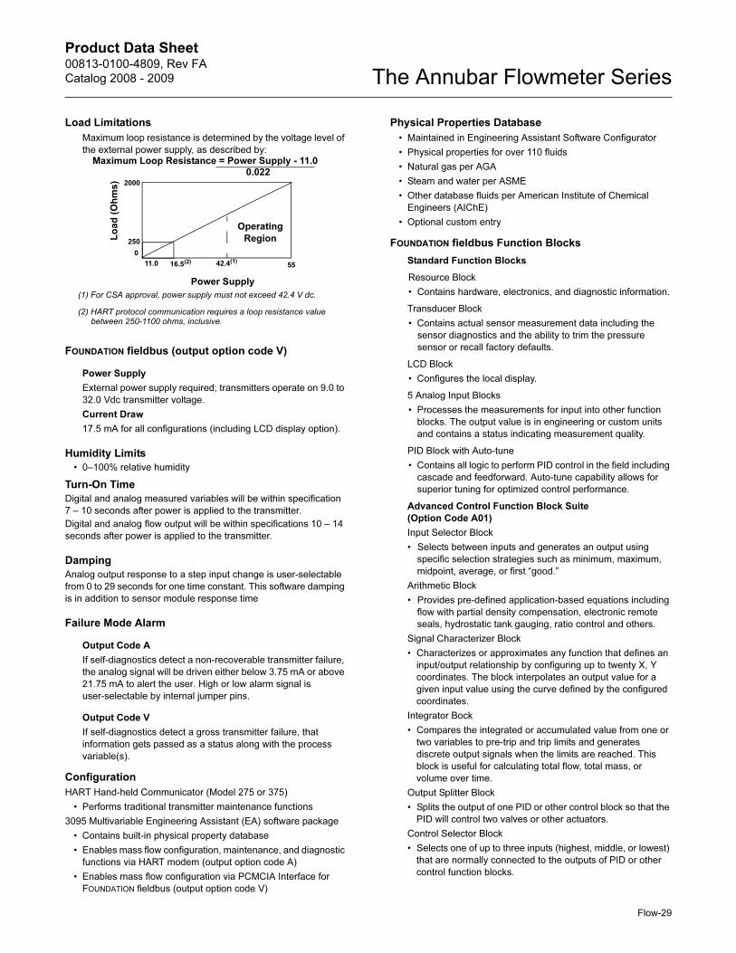
Product Data Sheet00813-0100-4809, Rev FA
Catalog 2008 - 2009 The Annubar Flowmeter Series
Flow-29
Load Limitations
Maximum loop resistance is determined by the voltage level of
the external power supply, as described by:
FOUNDATION fieldbus (output option code V)
Power Supply
External power supply required; transmitters operate on 9.0 to
32.0 Vdc transmitter voltage.
Current Draw
17.5 mA for all configurations (including LCD display option).
Humidity Limits
• 0–100% relative humidity
Turn-On Time
Digital and analog measured variables will be within specification
7 – 10 seconds after power is applied to the transmitter.
Digital and analog flow output will be within specifications 10 – 14
seconds after power is applied to the transmitter.
Damping
Analog output response to a step input change is user-selectable
from 0 to 29 seconds for one time constant. This software damping
is in addition to sensor module response time
Failure Mode Alarm
Output Code A
If self-diagnostics detect a non-recoverable transmitter failure,
the analog signal will be driven either below 3.75 mA or above
21.75 mA to alert the user. High or low alarm signal is
user-selectable by internal jumper pins.
Output Code V
If self-diagnostics detect a gross transmitter failure, that
information gets passed as a status along with the process
variable(s).
Configuration
HART Hand-held Communicator (Model 275 or 375)
• Performs traditional transmitter maintenance functions
3095 Multivariable Engineering Assistant (EA) software package
• Contains built-in physical property database
• Enables mass flow configuration, maintenance, and diagnostic
functions via HART modem (output option code A)
• Enables mass flow configuration via PCMCIA Interface for
FOUNDATION fieldbus (output option code V)
Physical Properties Database
• Maintained in Engineering Assistant Software Configurator
• Physical properties for over 110 fluids
• Natural gas per AGA
• Steam and water per ASME
• Other database fluids per American Institute of Chemical
Engineers (AIChE)
• Optional custom entry
FOUNDATION fieldbus Function Blocks
Standard Function Blocks
Resource Block
• Contains hardware, electronics, and diagnostic information.
Transducer Block
• Contains actual sensor measurement data including the
sensor diagnostics and the ability to trim the pressure
sensor or recall factory defaults.
LCD Block
• Configures the local display.
5 Analog Input Blocks
• Processes the measurements for input into other function
blocks. The output value is in engineering or custom units
and contains a status indicating measurement quality.
PID Block with Auto-tune
• Contains all logic to perform PID control in the field including
cascade and feedforward. Auto-tune capability allows for
superior tuning for optimized control performance.
Advanced Control Function Block Suite
(Option Code A01)
Input Selector Block
• Selects between inputs and generates an output using
specific selection strategies such as minimum, maximum,
midpoint, average, or first “good.”
Arithmetic Block
• Provides pre-defined application-based equations including
flow with partial density compensation, electronic remote
seals, hydrostatic tank gauging, ratio control and others.
Signal Characterizer Block
• Characterizes or approximates any function that defines an
input/output relationship by configuring up to twenty X, Y
coordinates. The block interpolates an output value for a
given input value using the curve defined by the configured
coordinates.
Integrator Bock
• Compares the integrated or accumulated value from one or
two variables to pre-trip and trip limits and generates
discrete output signals when the limits are reached. This
block is useful for calculating total flow, total mass, or
volume over time.
Output Splitter Block
• Splits the output of one PID or other control block so that the
PID will control two valves or other actuators.
Control Selector Block
• Selects one of up to three inputs (highest, middle, or lowest)
that are normally connected to the outputs of PID or other
control function blocks.
Lo
ad
(O
hm
s)
0
11.0 42.4(1)
55
Operating
Region
(1) For CSA approval, power supply must not exceed 42.4 V dc.
(2) HART protocol communication requires a loop resistance value between 250-1100 ohms, inclusive.
Power Supply
250
16.5(2)
Maximum Loop Resistance = Power Supply - 11.0
0.0222000
Product Data Sheet00813-0100-4809, Rev FA
Catalog 2008 - 2009The Annubar Flowmeter Series
Flow-30
Physical
Temperature Measurement
Integral RTD
• 100 Ohm platinum RTD
• 4-wire RTD (α = 0.00385)
Remote RTD
• 100 Ohm platinum RTD, spring loaded with 1/2-in.
NPT nipple and union (078 series with Rosemount 644
housing)
Thermowell
• 1/2-in. x 1/2-in NPT, 316 Stainless Steel with 1/2-in. Weld
coupling material to match process pipe.
Housing Connections1/2–14 NPT, G1/2, and M20 × 1.5 (CM20) conduit. HART interface
connections fixed to terminal block for output code A
Annubar Sensor Material
• 316 Stainless Steel
• Hastelloy 276
Annubar Type
See “Dimensional Drawings” on page 35
Pak-Lok Model (option P)
• Provided with a compression sealing mechanism rated up to
600# ANSI (1440 psig at 100 °F (99 bar at 38 °C))
• Graphite Packing (–300 to 850 °F (–184 to 454 °C))
Flanged with Opposite Side Support Model (option F)
• Provided with opposite side support, which is the same
material as the pipe and requires a second pipe penetration
• Sensor flange is the same material as the Annubar sensor and
the mounting flange is the same material as the pipe material
• Flanged mounting hardware: nuts, studs and gaskets (DIN
units supplied without nuts, studs and gaskets)
• SST: (–300 to 850 °F (–184 to 454 °C))
• Hastelloy: (–300 to 1250 °F (–184 to 677 °C))
Flange–Lok Model (option L)
• Flange–Lok assembly is supplied in 316 SST material.
• Flange-Lok mounting hardware: nuts, studs and gaskets (DIN
units supplied without nuts, studs and gaskets)
• –300 to 850 °F (–184 to 454 °C)
Flo-Tap Models (options G and M)
• Opposite side support is not available
• Threaded connection is not available with Sensor Size 3
• Gear Drive is not available with Sensor Size 1
• Packing gland required
• Packing Gland Material Temperature Limits
• PTFE: –40 to 400 °F (–40 to 204 °C)
• Graphite: –300 to 850 °F (–184 to 454 °C)
• Isolation valve included
• The isolation valve will carry the same pressure rating as the
sensor flange and mounting flange specified in the mounting
type
• Ball valves have a 300# limitation
• For threaded flo-tap models, the isolation valve NPT size is
11/4-in. (Sensor Size one) and 2-in. (Sensor Size 2).
Process-Wetted Parts
Integral Manifolds
• 316 SST
• Hastelloy C-276
Remote Manifolds
• 316 SST
• Hastelloy C-276
Transmitter Vent Valves and Process Flanges
• 316 SST
• Hastelloy C-276
• Glass-filled PTFE O-rings
Process Isolation Diaphragms
• 316 SST
• Hastelloy C-276
Integral Manifold O-Rings
• PTFE/Graphite
Non-Wetted Parts
Sensor Module Fill Fluid
• Silicone oil
• Inert Fill optional
Cover O-rings
• Buna-N
Remote Mounting Brackets
• SST
Sensor Mounting (including nuts, bolts, and gasket)
• Match Process Pipe Material
Transmitter Housing
• Low copper aluminum, NEMA 4x, IP65
• SST (optional)
Paint
• Polyurethane
Bolts
• CS
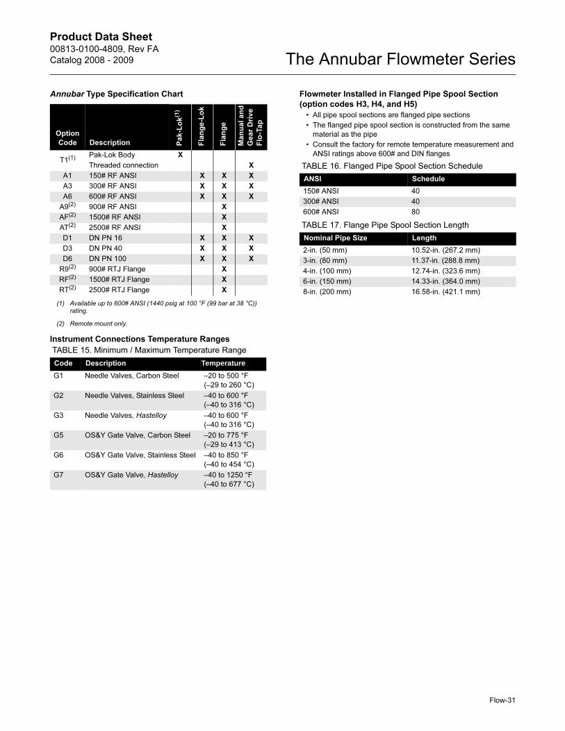
Product Data Sheet00813-0100-4809, Rev FA
Catalog 2008 - 2009 The Annubar Flowmeter Series
Flow-31
Annubar Type Specification Chart
Instrument Connections Temperature Ranges
Flowmeter Installed in Flanged Pipe Spool Section
(option codes H3, H4, and H5)
• All pipe spool sections are flanged pipe sections
• The flanged pipe spool section is constructed from the same
material as the pipe
• Consult the factory for remote temperature measurement and
ANSI ratings above 600# and DIN flanges
Option
Code Description Pa
k-L
ok(1)
(1) Available up to 600# ANSI (1440 psig at 100 °F (99 bar at 38 °C))rating.
Fla
ng
e-L
ok
Fla
ng
e
Ma
nu
al
an
d
Ge
ar
Dri
ve
Flo
-Ta
p
T1(1) Pak-Lok Body X
Threaded connection X
A1 150# RF ANSI X X X
A3 300# RF ANSI X X X
A6 600# RF ANSI X X X
A9(2)
(2) Remote mount only.
900# RF ANSI X
AF(2) 1500# RF ANSI X
AT(2) 2500# RF ANSI X
D1 DN PN 16 X X X
D3 DN PN 40 X X X
D6 DN PN 100 X X X
R9(2) 900# RTJ Flange X
RF(2) 1500# RTJ Flange X
RT(2) 2500# RTJ Flange X
TABLE 15. Minimum / Maximum Temperature Range
Code Description Temperature
G1 Needle Valves, Carbon Steel –20 to 500 °F
(–29 to 260 °C)
G2 Needle Valves, Stainless Steel –40 to 600 °F
(–40 to 316 °C)
G3 Needle Valves, Hastelloy –40 to 600 °F
(–40 to 316 °C)
G5 OS&Y Gate Valve, Carbon Steel –20 to 775 °F
(–29 to 413 °C)
G6 OS&Y Gate Valve, Stainless Steel –40 to 850 °F
(–40 to 454 °C)
G7 OS&Y Gate Valve, Hastelloy –40 to 1250 °F
(–40 to 677 °C)
TABLE 16. Flanged Pipe Spool Section Schedule
ANSI Schedule
150# ANSI 40
300# ANSI 40
600# ANSI 80
TABLE 17. Flange Pipe Spool Section Length
Nominal Pipe Size Length
2-in. (50 mm) 10.52-in. (267.2 mm)
3-in. (80 mm) 11.37-in. (288.8 mm)
4-in. (100 mm) 12.74-in. (323.6 mm)
6-in. (150 mm) 14.33-in. (364.0 mm)
8-in. (200 mm) 16.58-in. (421.1 mm)
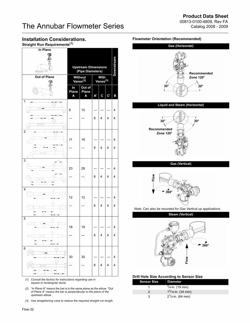
Product Data Sheet00813-0100-4809, Rev FA
Catalog 2008 - 2009The Annubar Flowmeter Series
Flow-32
Installation Considerations. Flowmeter Orientation (Recommended)
Drill Hole Size According to Sensor Size
Straight Run Requirements(1)
(1) Consult the factory for instructions regarding use in square or rectangular ducts.
Upstream Dimensions
(Pipe Diameters)
Do
wn
str
ea
m
Without
Vanes(2)
(2) “In Plane A” means the bar is in the same plane as the elbow. “Out of Plane A” means the bar is perpendicular to the plane of the upstream elbow.
With
Vanes(3)
(3) Use straightening vane to reduce the required straight run length.
In
Plane
A
Out of
Plane
A A’ C C’ B
1
8
—
10
—
—
8
—
4
—
4
4
4
2
11
—
16
—
—
8
—
4
—
4
4
4
3
23
—
28
—
—
8
—
4
—
4
4
4
4
12
—
12
—
—
8
—
4
—
4
4
4
5
18
—
18
—
—
8
—
4
—
4
4
4
6
30
—
30
—
—
8
—
4
—
4
4
4
Gas (Horizontal)
Liquid and Steam (Horizontal)
Gas (Vertical)
Steam (Vertical)
Sensor Size Diameter
1 3/4-in. (19 mm)
2 15/16-in. (34 mm)
3 21/2-in. (64 mm)
30° 30°
Recommended
Zone 120°
30°30°
Recommended
Zone 120°
Flo
w
360°
Note: Can also be mounted for Gas Vertical up applications.
360°
Flo
w
Out of Plane
In Plane
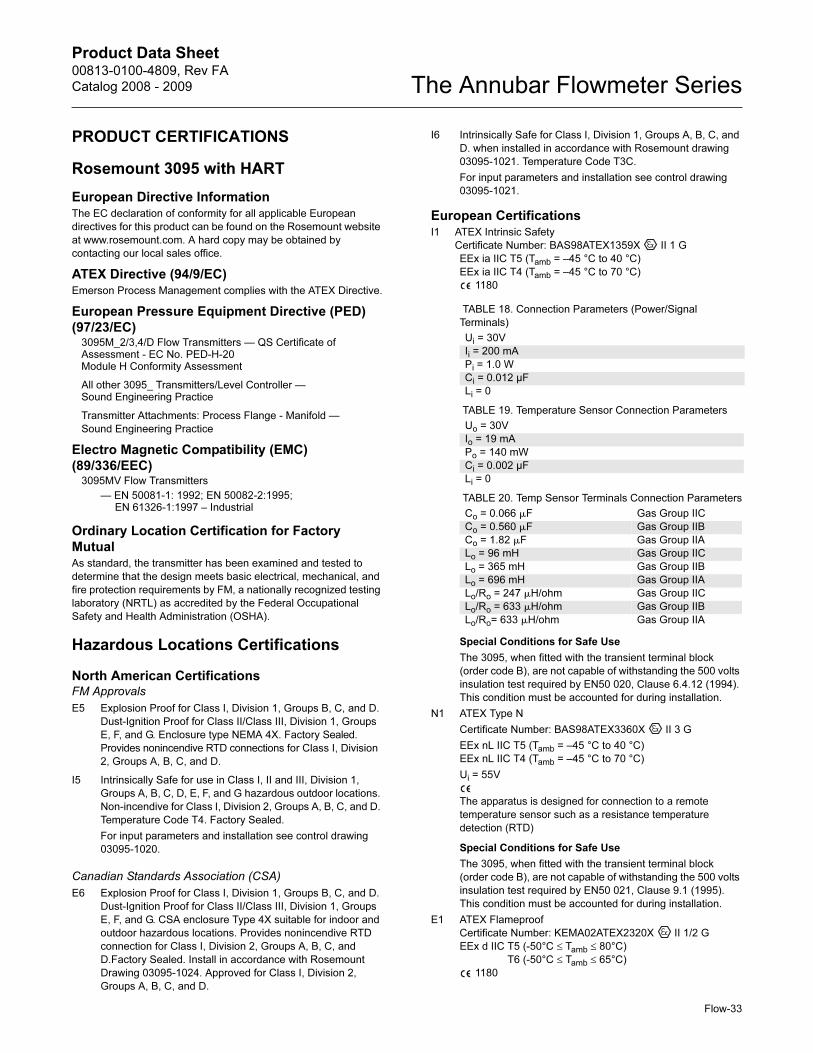
Product Data Sheet00813-0100-4809, Rev FA
Catalog 2008 - 2009 The Annubar Flowmeter Series
Flow-33
PRODUCT CERTIFICATIONS
Rosemount 3095 with HART
European Directive InformationThe EC declaration of conformity for all applicable European
directives for this product can be found on the Rosemount website
at www.rosemount.com. A hard copy may be obtained by
contacting our local sales office.
ATEX Directive (94/9/EC)Emerson Process Management complies with the ATEX Directive.
European Pressure Equipment Directive (PED)
(97/23/EC)3095M_2/3,4/D Flow Transmitters — QS Certificate of Assessment - EC No. PED-H-20Module H Conformity Assessment
All other 3095_ Transmitters/Level Controller — Sound Engineering Practice
Transmitter Attachments: Process Flange - Manifold —
Sound Engineering Practice
Electro Magnetic Compatibility (EMC)
(89/336/EEC)3095MV Flow Transmitters
— EN 50081-1: 1992; EN 50082-2:1995; EN 61326-1:1997 – Industrial
Ordinary Location Certification for Factory
MutualAs standard, the transmitter has been examined and tested to
determine that the design meets basic electrical, mechanical, and
fire protection requirements by FM, a nationally recognized testing
laboratory (NRTL) as accredited by the Federal Occupational
Safety and Health Administration (OSHA).
Hazardous Locations Certifications
North American CertificationsFM Approvals
E5 Explosion Proof for Class I, Division 1, Groups B, C, and D.
Dust-Ignition Proof for Class II/Class III, Division 1, Groups
E, F, and G. Enclosure type NEMA 4X. Factory Sealed.
Provides nonincendive RTD connections for Class I, Division
2, Groups A, B, C, and D.
I5 Intrinsically Safe for use in Class I, II and III, Division 1,
Groups A, B, C, D, E, F, and G hazardous outdoor locations.
Non-incendive for Class I, Division 2, Groups A, B, C, and D.
Temperature Code T4. Factory Sealed.
For input parameters and installation see control drawing
03095-1020.
Canadian Standards Association (CSA)
E6 Explosion Proof for Class I, Division 1, Groups B, C, and D.
Dust-Ignition Proof for Class II/Class III, Division 1, Groups
E, F, and G. CSA enclosure Type 4X suitable for indoor and
outdoor hazardous locations. Provides nonincendive RTD
connection for Class I, Division 2, Groups A, B, C, and
D.Factory Sealed. Install in accordance with Rosemount
Drawing 03095-1024. Approved for Class I, Division 2,
Groups A, B, C, and D.
I6 Intrinsically Safe for Class I, Division 1, Groups A, B, C, and
D. when installed in accordance with Rosemount drawing
03095-1021. Temperature Code T3C.
For input parameters and installation see control drawing
03095-1021.
European CertificationsI1 ATEX Intrinsic Safety
Certificate Number: BAS98ATEX1359X II 1 G
EEx ia IIC T5 (Tamb = –45 °C to 40 °C)
EEx ia IIC T4 (Tamb = –45 °C to 70 °C)
1180
Special Conditions for Safe Use
The 3095, when fitted with the transient terminal block
(order code B), are not capable of withstanding the 500 volts
insulation test required by EN50 020, Clause 6.4.12 (1994).
This condition must be accounted for during installation.
N1 ATEX Type N
Certificate Number: BAS98ATEX3360X II 3 G
EEx nL IIC T5 (Tamb = –45 °C to 40 °C)
EEx nL IIC T4 (Tamb = –45 °C to 70 °C)
Ui = 55V
The apparatus is designed for connection to a remote
temperature sensor such as a resistance temperature
detection (RTD)
Special Conditions for Safe Use
The 3095, when fitted with the transient terminal block
(order code B), are not capable of withstanding the 500 volts
insulation test required by EN50 021, Clause 9.1 (1995).
This condition must be accounted for during installation.
E1 ATEX Flameproof
Certificate Number: KEMA02ATEX2320X II 1/2 G
EEx d IIC T5 (-50°C ≤ Tamb ≤ 80°C)
T6 (-50°C ≤ Tamb ≤ 65°C)
1180
TABLE 18. Connection Parameters (Power/Signal
Terminals)
Ui = 30V
Ii = 200 mA
Pi = 1.0 W
Ci = 0.012 µF
Li = 0
TABLE 19. Temperature Sensor Connection Parameters
Uo = 30V
Io = 19 mA
Po = 140 mW
Ci = 0.002 µF
Li = 0
TABLE 20. Temp Sensor Terminals Connection Parameters
Co = 0.066 �F Gas Group IIC
Co = 0.560 �F Gas Group IIB
Co = 1.82 �F Gas Group IIA
Lo = 96 mH Gas Group IIC
Lo = 365 mH Gas Group IIB
Lo = 696 mH Gas Group IIA
Lo/Ro = 247 �H/ohm Gas Group IIC
Lo/Ro = 633 �H/ohm Gas Group IIB
Lo/Ro= 633 �H/ohm Gas Group IIA
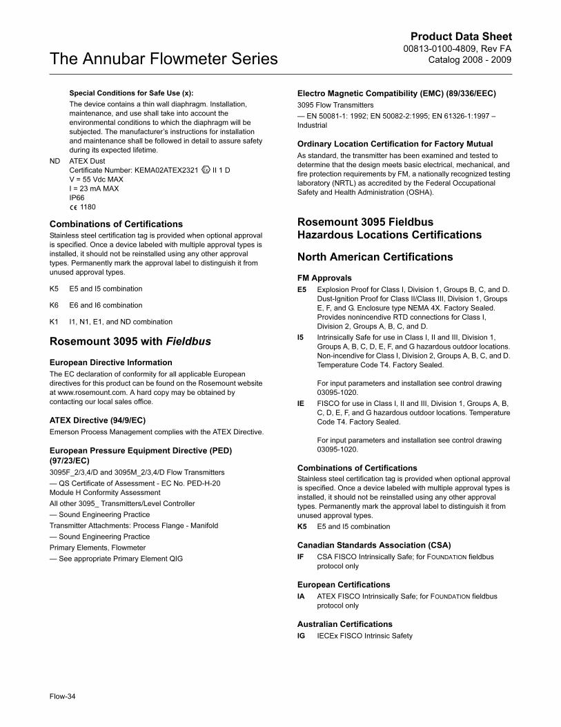
Product Data Sheet00813-0100-4809, Rev FA
Catalog 2008 - 2009The Annubar Flowmeter Series
Special Conditions for Safe Use (x):
The device contains a thin wall diaphragm. Installation,
maintenance, and use shall take into account the
environmental conditions to which the diaphragm will be
subjected. The manufacturer’s instructions for installation
and maintenance shall be followed in detail to assure safety
during its expected lifetime.
ND ATEX Dust
Certificate Number: KEMA02ATEX2321 II 1 D
V = 55 Vdc MAX
I = 23 mA MAX
IP66
1180
Combinations of CertificationsStainless steel certification tag is provided when optional approval
is specified. Once a device labeled with multiple approval types is
installed, it should not be reinstalled using any other approval
types. Permanently mark the approval label to distinguish it from
unused approval types.
K5 E5 and I5 combination
K6 E6 and I6 combination
K1 I1, N1, E1, and ND combination
Rosemount 3095 with Fieldbus
European Directive Information
The EC declaration of conformity for all applicable European
directives for this product can be found on the Rosemount website
at www.rosemount.com. A hard copy may be obtained by
contacting our local sales office.
ATEX Directive (94/9/EC)
Emerson Process Management complies with the ATEX Directive.
European Pressure Equipment Directive (PED)
(97/23/EC)
3095F_2/3,4/D and 3095M_2/3,4/D Flow Transmitters
— QS Certificate of Assessment - EC No. PED-H-20
Module H Conformity Assessment
All other 3095_ Transmitters/Level Controller
— Sound Engineering Practice
Transmitter Attachments: Process Flange - Manifold
— Sound Engineering Practice
Primary Elements, Flowmeter
— See appropriate Primary Element QIG
Electro Magnetic Compatibility (EMC) (89/336/EEC)
3095 Flow Transmitters
— EN 50081-1: 1992; EN 50082-2:1995; EN 61326-1:1997 –
Industrial
Ordinary Location Certification for Factory Mutual
As standard, the transmitter has been examined and tested to
determine that the design meets basic electrical, mechanical, and
fire protection requirements by FM, a nationally recognized testing
laboratory (NRTL) as accredited by the Federal Occupational
Safety and Health Administration (OSHA).
Rosemount 3095 Fieldbus Hazardous Locations Certifications
North American Certifications
FM Approvals
E5 Explosion Proof for Class I, Division 1, Groups B, C, and D.
Dust-Ignition Proof for Class II/Class III, Division 1, Groups
E, F, and G. Enclosure type NEMA 4X. Factory Sealed.
Provides nonincendive RTD connections for Class I,
Division 2, Groups A, B, C, and D.
I5 Intrinsically Safe for use in Class I, II and III, Division 1,
Groups A, B, C, D, E, F, and G hazardous outdoor locations.
Non-incendive for Class I, Division 2, Groups A, B, C, and D.
Temperature Code T4. Factory Sealed.
For input parameters and installation see control drawing
03095-1020.
IE FISCO for use in Class I, II and III, Division 1, Groups A, B,
C, D, E, F, and G hazardous outdoor locations. Temperature
Code T4. Factory Sealed.
For input parameters and installation see control drawing
03095-1020.
Combinations of Certifications
Stainless steel certification tag is provided when optional approval
is specified. Once a device labeled with multiple approval types is
installed, it should not be reinstalled using any other approval
types. Permanently mark the approval label to distinguish it from
unused approval types.
K5 E5 and I5 combination
Canadian Standards Association (CSA)
IF CSA FISCO Intrinsically Safe; for FOUNDATION fieldbus
protocol only
European Certifications
IA ATEX FISCO Intrinsically Safe; for FOUNDATION fieldbus
protocol only
Australian Certifications
IG IECEx FISCO Intrinsic Safety
Flow-34
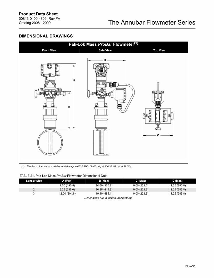
Product Data Sheet00813-0100-4809, Rev FA
Catalog 2008 - 2009 The Annubar Flowmeter Series
DIMENSIONAL DRAWINGS
Pak-Lok Mass ProBar Flowmeter(1)
Front View Side View Top View
(1) The Pak-Lok Annubar model is available up to 600# ANSI (1440 psig at 100 °F (99 bar at 38 °C)).
B
A
D
C
TABLE 21. Pak-Lok Mass ProBar Flowmeter Dimensional Data
Sensor Size A (Max) B (Max) C (Max) D (Max)
1 7.50 (190.5) 14.60 (370.8) 9.00 (228.6) 11.25 (285.8)
2 9.25 (235.0) 16.35 (415.3) 9.00 (228.6) 11.25 (285.8)
3 12.00 (304.8) 19.10 (485.1) 9.00 (228.6) 11.25 (285.8)
Dimensions are in inches (millimeters)
Flow-35
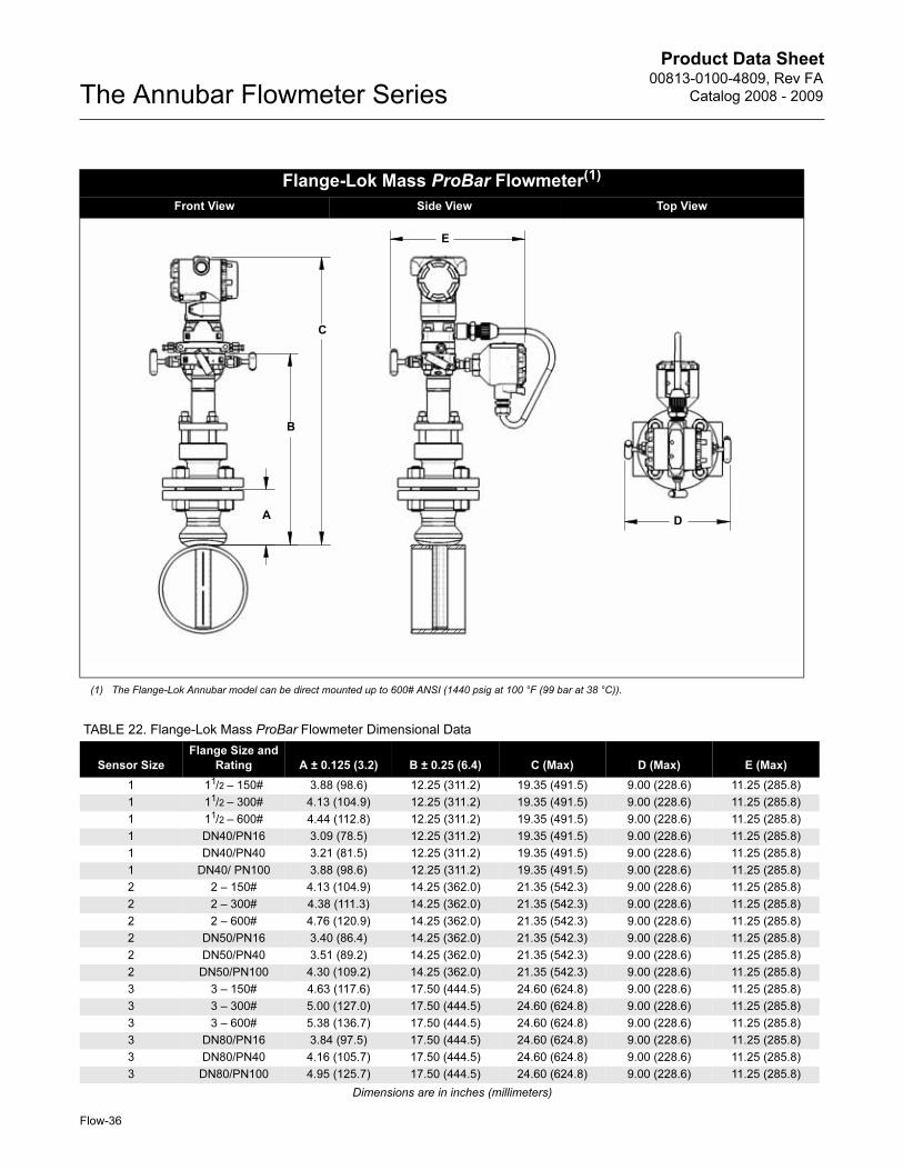
Product Data Sheet00813-0100-4809, Rev FA
Catalog 2008 - 2009The Annubar Flowmeter Series
Flange-Lok Mass ProBar Flowmeter(1)
Front View Side View Top View
(1) The Flange-Lok Annubar model can be direct mounted up to 600# ANSI (1440 psig at 100 °F (99 bar at 38 °C)).
B
AD
C
E
TABLE 22. Flange-Lok Mass ProBar Flowmeter Dimensional Data
Sensor Size
Flange Size and
Rating A ± 0.125 (3.2) B ± 0.25 (6.4) C (Max) D (Max) E (Max)
1 11/2 – 150# 3.88 (98.6) 12.25 (311.2) 19.35 (491.5) 9.00 (228.6) 11.25 (285.8)
1 11/2 – 300# 4.13 (104.9) 12.25 (311.2) 19.35 (491.5) 9.00 (228.6) 11.25 (285.8)
1 11/2 – 600# 4.44 (112.8) 12.25 (311.2) 19.35 (491.5) 9.00 (228.6) 11.25 (285.8)
1 DN40/PN16 3.09 (78.5) 12.25 (311.2) 19.35 (491.5) 9.00 (228.6) 11.25 (285.8)
1 DN40/PN40 3.21 (81.5) 12.25 (311.2) 19.35 (491.5) 9.00 (228.6) 11.25 (285.8)
1 DN40/ PN100 3.88 (98.6) 12.25 (311.2) 19.35 (491.5) 9.00 (228.6) 11.25 (285.8)
2 2 – 150# 4.13 (104.9) 14.25 (362.0) 21.35 (542.3) 9.00 (228.6) 11.25 (285.8)
2 2 – 300# 4.38 (111.3) 14.25 (362.0) 21.35 (542.3) 9.00 (228.6) 11.25 (285.8)
2 2 – 600# 4.76 (120.9) 14.25 (362.0) 21.35 (542.3) 9.00 (228.6) 11.25 (285.8)
2 DN50/PN16 3.40 (86.4) 14.25 (362.0) 21.35 (542.3) 9.00 (228.6) 11.25 (285.8)
2 DN50/PN40 3.51 (89.2) 14.25 (362.0) 21.35 (542.3) 9.00 (228.6) 11.25 (285.8)
2 DN50/PN100 4.30 (109.2) 14.25 (362.0) 21.35 (542.3) 9.00 (228.6) 11.25 (285.8)
3 3 – 150# 4.63 (117.6) 17.50 (444.5) 24.60 (624.8) 9.00 (228.6) 11.25 (285.8)
3 3 – 300# 5.00 (127.0) 17.50 (444.5) 24.60 (624.8) 9.00 (228.6) 11.25 (285.8)
3 3 – 600# 5.38 (136.7) 17.50 (444.5) 24.60 (624.8) 9.00 (228.6) 11.25 (285.8)
3 DN80/PN16 3.84 (97.5) 17.50 (444.5) 24.60 (624.8) 9.00 (228.6) 11.25 (285.8)
3 DN80/PN40 4.16 (105.7) 17.50 (444.5) 24.60 (624.8) 9.00 (228.6) 11.25 (285.8)
3 DN80/PN100 4.95 (125.7) 17.50 (444.5) 24.60 (624.8) 9.00 (228.6) 11.25 (285.8)
Dimensions are in inches (millimeters)
Flow-36
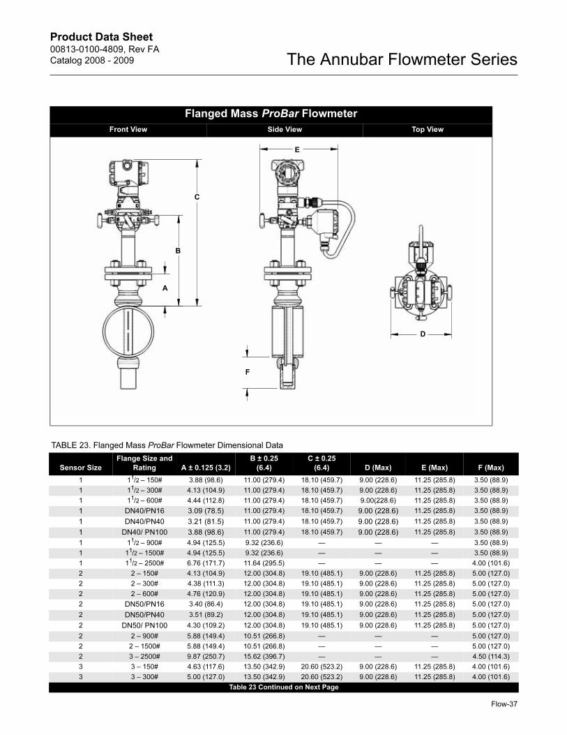
Product Data Sheet00813-0100-4809, Rev FA
Catalog 2008 - 2009 The Annubar Flowmeter Series
Flow-37
Flanged Mass ProBar Flowmeter
Front View Side View Top View
B
A
D
C
E
F
TABLE 23. Flanged Mass ProBar Flowmeter Dimensional Data
Sensor Size
Flange Size and
Rating A ± 0.125 (3.2)
B ± 0.25
(6.4)
C ± 0.25
(6.4) D (Max) E (Max) F (Max)
1 11/2 – 150# 3.88 (98.6) 11.00 (279.4) 18.10 (459.7) 9.00 (228.6) 11.25 (285.8) 3.50 (88.9)
1 11/2 – 300# 4.13 (104.9) 11.00 (279.4) 18.10 (459.7) 9.00 (228.6) 11.25 (285.8) 3.50 (88.9)
1 11/2 – 600# 4.44 (112.8) 11.00 (279.4) 18.10 (459.7) 9.00(228.6) 11.25 (285.8) 3.50 (88.9)
1 DN40/PN16 3.09 (78.5) 11.00 (279.4) 18.10 (459.7) 9.00 (228.6) 11.25 (285.8) 3.50 (88.9)
1 DN40/PN40 3.21 (81.5) 11.00 (279.4) 18.10 (459.7) 9.00 (228.6) 11.25 (285.8) 3.50 (88.9)
1 DN40/ PN100 3.88 (98.6) 11.00 (279.4) 18.10 (459.7) 9.00 (228.6) 11.25 (285.8) 3.50 (88.9)
1 11/2 – 900# 4.94 (125.5) 9.32 (236.6) — — — 3.50 (88.9)
1 11/2 – 1500# 4.94 (125.5) 9.32 (236.6) — — — 3.50 (88.9)
1 11/2 – 2500# 6.76 (171.7) 11.64 (295.5) — — — 4.00 (101.6)
2 2 – 150# 4.13 (104.9) 12.00 (304.8) 19.10 (485.1) 9.00 (228.6) 11.25 (285.8) 5.00 (127.0)
2 2 – 300# 4.38 (111.3) 12.00 (304.8) 19.10 (485.1) 9.00 (228.6) 11.25 (285.8) 5.00 (127.0)
2 2 – 600# 4.76 (120.9) 12.00 (304.8) 19.10 (485.1) 9.00 (228.6) 11.25 (285.8) 5.00 (127.0)
2 DN50/PN16 3.40 (86.4) 12.00 (304.8) 19.10 (485.1) 9.00 (228.6) 11.25 (285.8) 5.00 (127.0)
2 DN50/PN40 3.51 (89.2) 12.00 (304.8) 19.10 (485.1) 9.00 (228.6) 11.25 (285.8) 5.00 (127.0)
2 DN50/ PN100 4.30 (109.2) 12.00 (304.8) 19.10 (485.1) 9.00 (228.6) 11.25 (285.8) 5.00 (127.0)
2 2 – 900# 5.88 (149.4) 10.51 (266.8) — — — 5.00 (127.0)
2 2 – 1500# 5.88 (149.4) 10.51 (266.8) — — — 5.00 (127.0)
2 3 – 2500# 9.87 (250.7) 15.62 (396.7) — — — 4.50 (114.3)
3 3 – 150# 4.63 (117.6) 13.50 (342.9) 20.60 (523.2) 9.00 (228.6) 11.25 (285.8) 4.00 (101.6)
3 3 – 300# 5.00 (127.0) 13.50 (342.9) 20.60 (523.2) 9.00 (228.6) 11.25 (285.8) 4.00 (101.6)
Table 23 Continued on Next Page
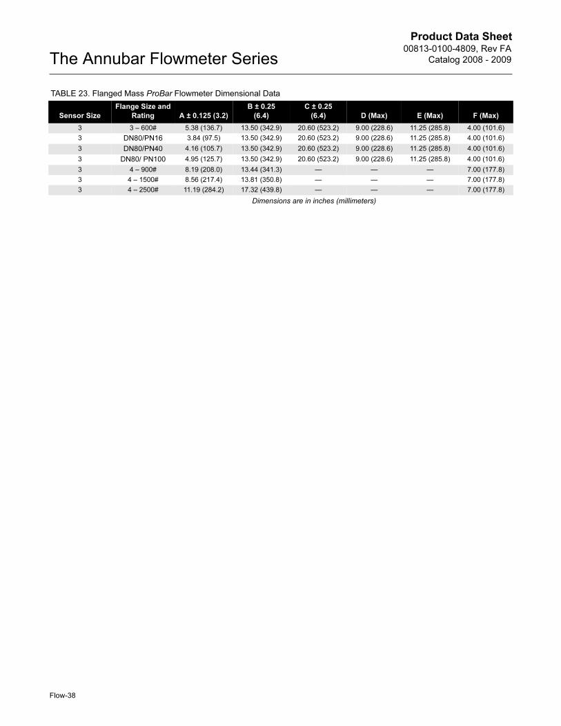
Product Data Sheet00813-0100-4809, Rev FA
Catalog 2008 - 2009The Annubar Flowmeter Series
3 3 – 600# 5.38 (136.7) 13.50 (342.9) 20.60 (523.2) 9.00 (228.6) 11.25 (285.8) 4.00 (101.6)
3 DN80/PN16 3.84 (97.5) 13.50 (342.9) 20.60 (523.2) 9.00 (228.6) 11.25 (285.8) 4.00 (101.6)
3 DN80/PN40 4.16 (105.7) 13.50 (342.9) 20.60 (523.2) 9.00 (228.6) 11.25 (285.8) 4.00 (101.6)
3 DN80/ PN100 4.95 (125.7) 13.50 (342.9) 20.60 (523.2) 9.00 (228.6) 11.25 (285.8) 4.00 (101.6)
3 4 – 900# 8.19 (208.0) 13.44 (341.3) — — — 7.00 (177.8)
3 4 – 1500# 8.56 (217.4) 13.81 (350.8) — — — 7.00 (177.8)
3 4 – 2500# 11.19 (284.2) 17.32 (439.8) — — — 7.00 (177.8)
Dimensions are in inches (millimeters)
TABLE 23. Flanged Mass ProBar Flowmeter Dimensional Data
Sensor Size
Flange Size and
Rating A ± 0.125 (3.2)
B ± 0.25
(6.4)
C ± 0.25
(6.4) D (Max) E (Max) F (Max)
Flow-38
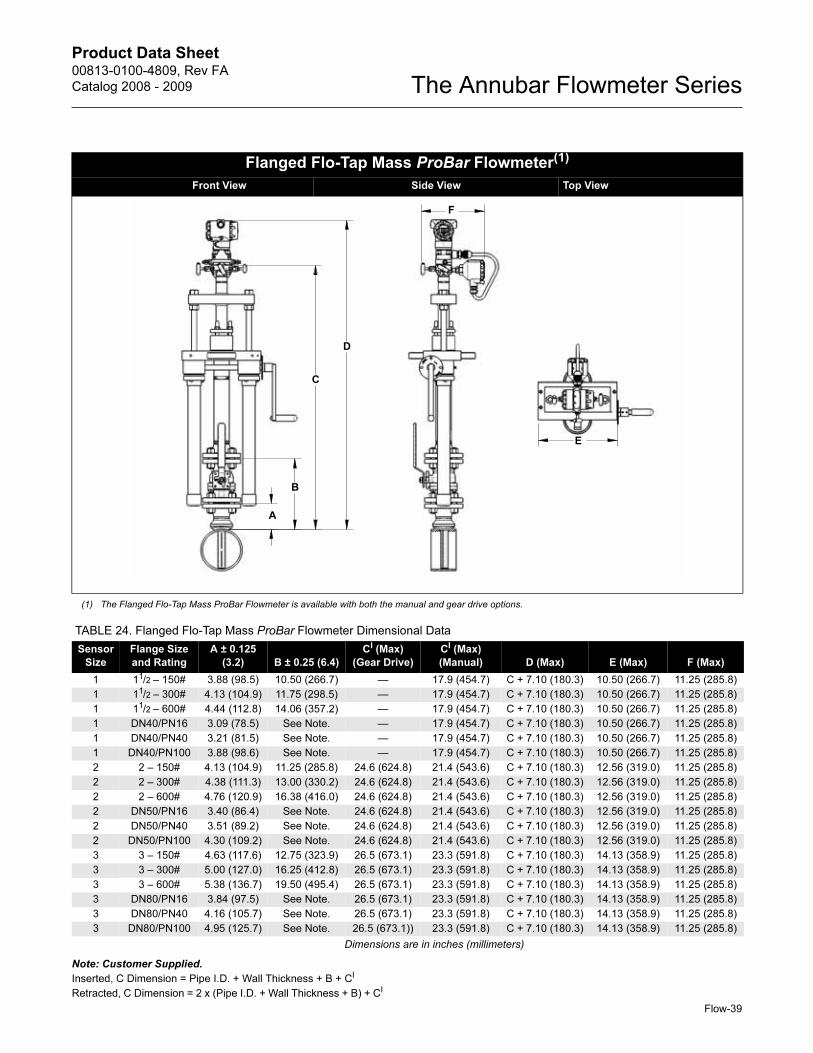
Product Data Sheet00813-0100-4809, Rev FA
Catalog 2008 - 2009 The Annubar Flowmeter Series
Flow-39
Note: Customer Supplied.
Inserted, C Dimension = Pipe I.D. + Wall Thickness + B + CI
Retracted, C Dimension = 2 x (Pipe I.D. + Wall Thickness + B) + CI
Flanged Flo-Tap Mass ProBar Flowmeter(1)
_________Front View Side View Top View______________________
(1) The Flanged Flo-Tap Mass ProBar Flowmeter is available with both the manual and gear drive options.
B
A
D
C
E
F
TABLE 24. Flanged Flo-Tap Mass ProBar Flowmeter Dimensional Data
Sensor
Size
Flange Size
and Rating
A ± 0.125
(3.2) B ± 0.25 (6.4)
CI (Max)
(Gear Drive)
CI (Max)
(Manual) D (Max) E (Max) F (Max)
1 11/2 – 150# 3.88 (98.5) 10.50 (266.7) — 17.9 (454.7) C + 7.10 (180.3) 10.50 (266.7) 11.25 (285.8)
1 11/2 – 300# 4.13 (104.9) 11.75 (298.5) — 17.9 (454.7) C + 7.10 (180.3) 10.50 (266.7) 11.25 (285.8)
1 11/2 – 600# 4.44 (112.8) 14.06 (357.2) — 17.9 (454.7) C + 7.10 (180.3) 10.50 (266.7) 11.25 (285.8)
1 DN40/PN16 3.09 (78.5) See Note. — 17.9 (454.7) C + 7.10 (180.3) 10.50 (266.7) 11.25 (285.8)
1 DN40/PN40 3.21 (81.5) See Note. — 17.9 (454.7) C + 7.10 (180.3) 10.50 (266.7) 11.25 (285.8)
1 DN40/PN100 3.88 (98.6) See Note. — 17.9 (454.7) C + 7.10 (180.3) 10.50 (266.7) 11.25 (285.8)
2 2 – 150# 4.13 (104.9) 11.25 (285.8) 24.6 (624.8) 21.4 (543.6) C + 7.10 (180.3) 12.56 (319.0) 11.25 (285.8)
2 2 – 300# 4.38 (111.3) 13.00 (330.2) 24.6 (624.8) 21.4 (543.6) C + 7.10 (180.3) 12.56 (319.0) 11.25 (285.8)
2 2 – 600# 4.76 (120.9) 16.38 (416.0) 24.6 (624.8) 21.4 (543.6) C + 7.10 (180.3) 12.56 (319.0) 11.25 (285.8)
2 DN50/PN16 3.40 (86.4) See Note. 24.6 (624.8) 21.4 (543.6) C + 7.10 (180.3) 12.56 (319.0) 11.25 (285.8)
2 DN50/PN40 3.51 (89.2) See Note. 24.6 (624.8) 21.4 (543.6) C + 7.10 (180.3) 12.56 (319.0) 11.25 (285.8)
2 DN50/PN100 4.30 (109.2) See Note. 24.6 (624.8) 21.4 (543.6) C + 7.10 (180.3) 12.56 (319.0) 11.25 (285.8)
3 3 – 150# 4.63 (117.6) 12.75 (323.9) 26.5 (673.1) 23.3 (591.8) C + 7.10 (180.3) 14.13 (358.9) 11.25 (285.8)
3 3 – 300# 5.00 (127.0) 16.25 (412.8) 26.5 (673.1) 23.3 (591.8) C + 7.10 (180.3) 14.13 (358.9) 11.25 (285.8)
3 3 – 600# 5.38 (136.7) 19.50 (495.4) 26.5 (673.1) 23.3 (591.8) C + 7.10 (180.3) 14.13 (358.9) 11.25 (285.8)
3 DN80/PN16 3.84 (97.5) See Note. 26.5 (673.1) 23.3 (591.8) C + 7.10 (180.3) 14.13 (358.9) 11.25 (285.8)
3 DN80/PN40 4.16 (105.7) See Note. 26.5 (673.1) 23.3 (591.8) C + 7.10 (180.3) 14.13 (358.9) 11.25 (285.8)
3 DN80/PN100 4.95 (125.7) See Note. 26.5 (673.1)) 23.3 (591.8) C + 7.10 (180.3) 14.13 (358.9) 11.25 (285.8)
Dimensions are in inches (millimeters)
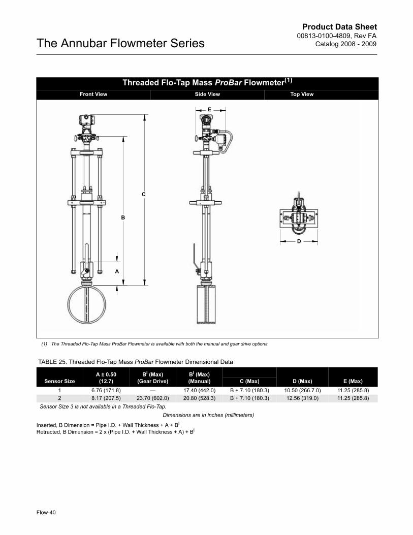
Product Data Sheet00813-0100-4809, Rev FA
Catalog 2008 - 2009The Annubar Flowmeter Series
Flow-40
Inserted, B Dimension = Pipe I.D. + Wall Thickness + A + BI
Retracted, B Dimension = 2 x (Pipe I.D. + Wall Thickness + A) + BI
Threaded Flo-Tap Mass ProBar Flowmeter(1)
Front View Side View Top View_____________
(1) The Threaded Flo-Tap Mass ProBar Flowmeter is available with both the manual and gear drive options.
B
A
D
C
E
E
TABLE 25. Threaded Flo-Tap Mass ProBar Flowmeter Dimensional Data
Sensor Size
A ± 0.50
(12.7)
BI (Max)
(Gear Drive)
BI (Max)
(Manual) D (Max) E (Max)C (Max)
1 6.76 (171.8) — 17.40 (442.0) B + 7.10 (180.3) 10.50 (266.7.0) 11.25 (285.8)
2 8.17 (207.5) 23.70 (602.0) 20.80 (528.3) B + 7.10 (180.3) 12.56 (319.0) 11.25 (285.8)
Sensor Size 3 is not available in a Threaded Flo-Tap.
Dimensions are in inches (millimeters)
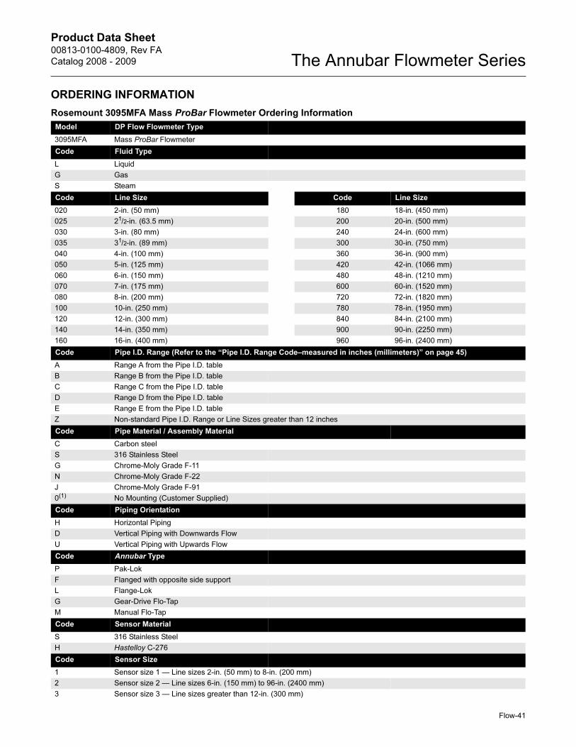
Product Data Sheet00813-0100-4809, Rev FA
Catalog 2008 - 2009 The Annubar Flowmeter Series
Flow-41
ORDERING INFORMATION
Rosemount 3095MFA Mass ProBar Flowmeter Ordering Information
Model DP Flow Flowmeter Type
3095MFA Mass ProBar Flowmeter
Code Fluid Type
L Liquid
G Gas
S Steam
Code Line Size Code Line Size
020 2-in. (50 mm) 180 18-in. (450 mm)
025 21/2-in. (63.5 mm) 200 20-in. (500 mm)
030 3-in. (80 mm) 240 24-in. (600 mm)
035 31/2-in. (89 mm) 300 30-in. (750 mm)
040 4-in. (100 mm) 360 36-in. (900 mm)
050 5-in. (125 mm) 420 42-in. (1066 mm)
060 6-in. (150 mm) 480 48-in. (1210 mm)
070 7-in. (175 mm) 600 60-in. (1520 mm)
080 8-in. (200 mm) 720 72-in. (1820 mm)
100 10-in. (250 mm) 780 78-in. (1950 mm)
120 12-in. (300 mm) 840 84-in. (2100 mm)
140 14-in. (350 mm) 900 90-in. (2250 mm)
160 16-in. (400 mm) 960 96-in. (2400 mm)
Code Pipe I.D. Range (Refer to the “Pipe I.D. Range Code–measured in inches (millimeters)” on page 45)
A Range A from the Pipe I.D. table
B Range B from the Pipe I.D. table
C Range C from the Pipe I.D. table
D Range D from the Pipe I.D. table
E Range E from the Pipe I.D. table
Z Non-standard Pipe I.D. Range or Line Sizes greater than 12 inches
Code Pipe Material / Assembly Material
C Carbon steel
S 316 Stainless Steel
G Chrome-Moly Grade F-11
N Chrome-Moly Grade F-22
J Chrome-Moly Grade F-91
0(1) No Mounting (Customer Supplied)
Code Piping Orientation
H Horizontal Piping
D Vertical Piping with Downwards Flow
U Vertical Piping with Upwards Flow
Code Annubar Type
P Pak-Lok
F Flanged with opposite side support
L Flange-Lok
G Gear-Drive Flo-Tap
M Manual Flo-Tap
Code Sensor Material
S 316 Stainless Steel
H Hastelloy C-276
Code Sensor Size
1 Sensor size 1 — Line sizes 2-in. (50 mm) to 8-in. (200 mm)
2 Sensor size 2 — Line sizes 6-in. (150 mm) to 96-in. (2400 mm)
3 Sensor size 3 — Line sizes greater than 12-in. (300 mm)
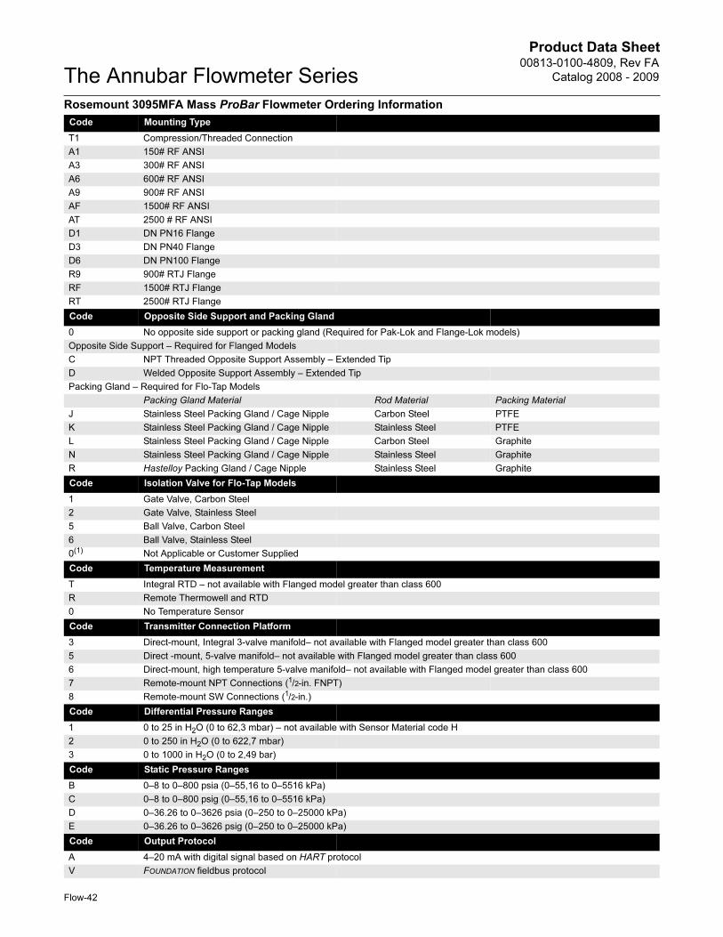
Product Data Sheet00813-0100-4809, Rev FA
Catalog 2008 - 2009The Annubar Flowmeter Series
Flow-42
Code Mounting Type
T1 Compression/Threaded Connection
A1 150# RF ANSI
A3 300# RF ANSI
A6 600# RF ANSI
A9 900# RF ANSI
AF 1500# RF ANSI
AT 2500 # RF ANSI
D1 DN PN16 Flange
D3 DN PN40 Flange
D6 DN PN100 Flange
R9 900# RTJ Flange
RF 1500# RTJ Flange
RT 2500# RTJ Flange
Code Opposite Side Support and Packing Gland
0 No opposite side support or packing gland (Required for Pak-Lok and Flange-Lok models)
Opposite Side Support – Required for Flanged Models
C NPT Threaded Opposite Support Assembly – Extended Tip
D Welded Opposite Support Assembly – Extended Tip
Packing Gland – Required for Flo-Tap Models
Packing Gland Material Rod Material Packing Material
J Stainless Steel Packing Gland / Cage Nipple Carbon Steel PTFE
K Stainless Steel Packing Gland / Cage Nipple Stainless Steel PTFE
L Stainless Steel Packing Gland / Cage Nipple Carbon Steel Graphite
N Stainless Steel Packing Gland / Cage Nipple Stainless Steel Graphite
R Hastelloy Packing Gland / Cage Nipple Stainless Steel Graphite
Code Isolation Valve for Flo-Tap Models
1 Gate Valve, Carbon Steel
2 Gate Valve, Stainless Steel
5 Ball Valve, Carbon Steel
6 Ball Valve, Stainless Steel
0(1) Not Applicable or Customer Supplied
Code Temperature Measurement
T Integral RTD – not available with Flanged model greater than class 600
R Remote Thermowell and RTD
0 No Temperature Sensor
Code Transmitter Connection Platform
3 Direct-mount, Integral 3-valve manifold– not available with Flanged model greater than class 600
5 Direct -mount, 5-valve manifold– not available with Flanged model greater than class 600
6 Direct-mount, high temperature 5-valve manifold– not available with Flanged model greater than class 600
7 Remote-mount NPT Connections (1/2-in. FNPT)
8 Remote-mount SW Connections (1/2-in.)
Code Differential Pressure Ranges
1 0 to 25 in H2O (0 to 62,3 mbar) – not available with Sensor Material code H
2 0 to 250 in H2O (0 to 622,7 mbar)
3 0 to 1000 in H2O (0 to 2,49 bar)
Code Static Pressure Ranges
B 0–8 to 0–800 psia (0–55,16 to 0–5516 kPa)
C 0–8 to 0–800 psig (0–55,16 to 0–5516 kPa)
D 0–36.26 to 0–3626 psia (0–250 to 0–25000 kPa)
E 0–36.26 to 0–3626 psig (0–250 to 0–25000 kPa)
Code Output Protocol
A 4–20 mA with digital signal based on HART protocol
V FOUNDATION fieldbus protocol
Rosemount 3095MFA Mass ProBar Flowmeter Ordering Information
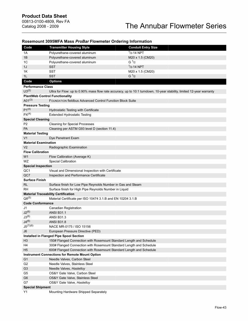
Product Data Sheet00813-0100-4809, Rev FA
Catalog 2008 - 2009 The Annubar Flowmeter Series
Code Transmitter Housing Style Conduit Entry Size
1A Polyurethane-covered aluminum 1/2-14 NPT
1B Polyurethane-covered aluminum M20 x 1.5 (CM20)
1C Polyurethane-covered aluminum G 1/2
1J SST 1/2-14 NPT
1K SST M20 x 1.5 (CM20)
1L SST G 1/2
Code Options
Performance Class
U3(2) Ultra for Flow: up to 0.90% mass flow rate accuracy, up to 10:1 turndown, 10-year stability, limited 12-year warranty
PlantWeb Control Functionality
A01(3) FOUNDATION fieldbus Advanced Control Function Block Suite
Pressure Testing
P1(4) Hydrostatic Testing with Certificate
PX(4) Extended Hydrostatic Testing
Special Cleaning
P2 Cleaning for Special Processes
PA Cleaning per ASTM G93 level D (section 11.4)
Material Testing
V1 Dye Penetrant Exam
Material Examination
V2 Radiographic Examination
Flow Calibration
W1 Flow Calibration (Average K)
WZ Special Calibration
Special Inspection
QC1 Visual and Dimensional Inspection with Certificate
QC7 Inspection and Performance Certificate
Surface Finish
RL Surface finish for Low Pipe Reynolds Number in Gas and Steam
RH Surface finish for High Pipe Reynolds Number in Liquid
Material Traceability Certification
Q8(5) Material Certificate per ISO 10474 3.1.B and EN 10204 3.1.B
Code Conformance
J1 Canadian Registration
J2(6) ANSI B31.1
J3(6) ANSI B31.3
J4(6) ANSI B31.8
J5(7)(8) NACE MR-0175 / ISO 15156
J6 European Pressure Directive (PED)
Installed in Flanged Pipe Spool Section
H3 150# Flanged Connection with Rosemount Standard Length and Schedule
H4 300# Flanged Connection with Rosemount Standard Length and Schedule
H5 600# Flanged Connection with Rosemount Standard Length and Schedule
Instrument Connections for Remote Mount Option
G1 Needle Valves, Carbon Steel
G2 Needle Valves, Stainless Steel
G3 Needle Valves, Hastelloy
G5 OS&Y Gate Valve, Carbon Steel
G6 OS&Y Gate Valve, Stainless Steel
G7 OS&Y Gate Valve, Hastelloy
Special Shipment
Y1 Mounting Hardware Shipped Separately
Rosemount 3095MFA Mass ProBar Flowmeter Ordering Information
Flow-43
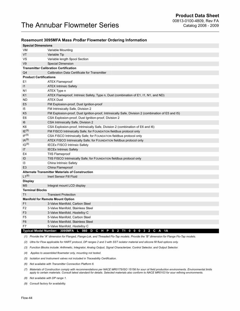
Product Data Sheet00813-0100-4809, Rev FA
Catalog 2008 - 2009The Annubar Flowmeter Series
Special Dimensions
VM Variable Mounting
VT Variable Tip
VS Variable length Spool Section
V9 Special Dimension
Transmitter Calibration Certification
Q4 Calibration Data Certificate for Transmitter
Product Certifications
E1 ATEX Flameproof
I1 ATEX Intrinsic Safety
N1 ATEX Type n
K1 ATEX Flameproof, Intrinsic Safety, Type n, Dust (combination of E1, I1, N1, and ND)
ND ATEX Dust
E5 FM Explosion-proof, Dust Ignition-proof
I5 FM Intrinsically Safe, Division 2
K5 FM Explosion-proof, Dust Ignition-proof, Intrinsically Safe, Division 2 (combination of E5 and I5)
E6 CSA Explosion-proof, Dust Ignition-proof, Division 2
I6 CSA Intrinsically Safe, Division 2
K6 CSA Explosion-proof, Intrinsically Safe, Division 2 (combination of E6 and I6)
IE(9) FM FISCO Intrinsically Safe; for FOUNDATION fieldbus protocol only
IF(9) CSA FISCO Intrinsically Safe; for FOUNDATION fieldbus protocol only
IA(9) ATEX FISCO Intrinsically Safe; for FOUNDATION fieldbus protocol only
IG(9) IECEx FISCO Intrinsic Safety
I7 IECEx Intrinsic Safety
E4 TIIS Flameproof
ID TIIS FISCO Intrinsically Safe; for FOUNDATION fieldbus protocol only
I3 China Intrinsic Safety
E3 China Flameproof
Alternate Transmitter Materials of Construction
L1(8) Inert Sensor Fill Fluid
Display
M5 Integral mount LCD display
Terminal Blocks
T1 Transient Protection
Manifold for Remote Mount Option
F1 3-Valve Manifold, Carbon Steel
F2 3-Valve Manifold, Stainless Steel
F3 3-Valve Manifold, Hastelloy C
F5 5-Valve Manifold, Carbon Steel
F6 5-Valve Manifold, Stainless Steel
F7 5-Valve Manifold, Hastelloy C
Typical Model Number: 3095MFA L 060 D C H P S 2 T1 0 0 0 3 2 C A 1A
(1) Provide the “A” dimension for Flanged, Flange-Lok, and Threaded Flo-Tap models. Provide the “B” dimension for Flange Flo-Tap models.
(2) Ultra for Flow applicable for HART protocol, DP ranges 2 and 3 with SST isolator material and silicone fill fluid options only.
(3) Function Blocks include: Arithmetic, Integrator, Analog Output, Signal Characterizer, Control Selector, and Output Selector.
(4) Applies to assembled flowmeter only, mounting not tested.
(5) Isolation and Instrument valves not included in Traceability Certification.
(6) Not available with Transmitter Connection Platform 6.
(7) Materials of Construction comply with recommendations per NACE MR0175/ISO 15156 for sour oil field production environments. Environmental limits apply to certain materials. Consult latest standard for details. Selected materials also conform to NACE MR0103 for sour refining environments.
(8) Not available with DP range 1.
(9) Consult factory for availability.
Rosemount 3095MFA Mass ProBar Flowmeter Ordering Information
Flow-44
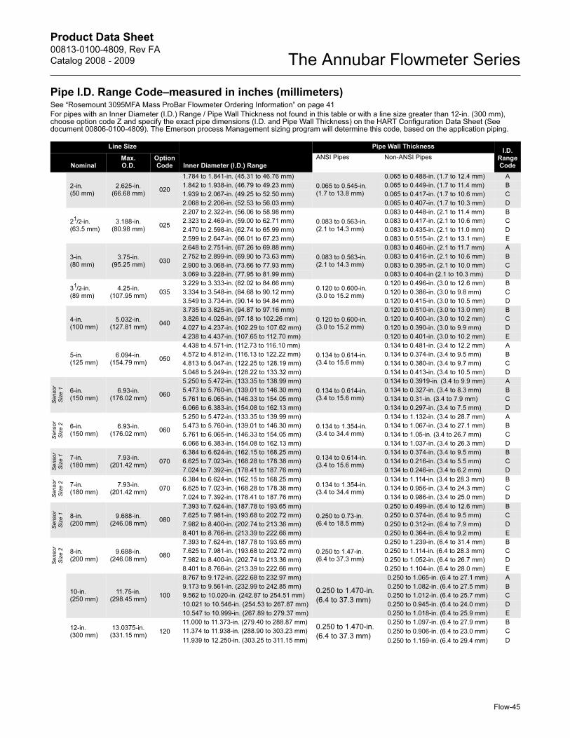
Product Data Sheet00813-0100-4809, Rev FA
Catalog 2008 - 2009 The Annubar Flowmeter Series
Flow-45
Pipe I.D. Range Code–measured in inches (millimeters)See “Rosemount 3095MFA Mass ProBar Flowmeter Ordering Information” on page 41
For pipes with an Inner Diameter (I.D.) Range / Pipe Wall Thickness not found in this table or with a line size greater than 12-in. (300 mm), choose option code Z and specify the exact pipe dimensions (I.D. and Pipe Wall Thickness) on the HART Configuration Data Sheet (See document 00806-0100-4809). The Emerson process Management sizing program will determine this code, based on the application piping.
Line Size
Inner Diameter (I.D.) Range
Pipe Wall ThicknessI.D.
Range CodeNominal
Max. O.D.
Option Code
ANSI Pipes Non-ANSI Pipes
2-in. (50 mm)
2.625-in. (66.68 mm)
020
1.784 to 1.841-in. (45.31 to 46.76 mm)
0.065 to 0.545-in. (1.7 to 13.8 mm)
0.065 to 0.488-in. (1.7 to 12.4 mm) A
1.842 to 1.938-in. (46.79 to 49.23 mm) 0.065 to 0.449-in. (1.7 to 11.4 mm) B
1.939 to 2.067-in. (49.25 to 52.50 mm) 0.065 to 0.417-in. (1.7 to 10.6 mm) C
2.068 to 2.206-in. (52.53 to 56.03 mm) 0.065 to 0.407-in. (1.7 to 10.3 mm) D
21/2-in. (63.5 mm)
3.188-in. (80.98 mm)
025
2.207 to 2.322-in. (56.06 to 58.98 mm)
0.083 to 0.563-in. (2.1 to 14.3 mm)
0.083 to 0.448-in. (2.1 to 11.4 mm) B
2.323 to 2.469-in. (59.00 to 62.71 mm) 0.083 to 0.417-in. (2.1 to 10.6 mm) C
2.470 to 2.598-in. (62.74 to 65.99 mm) 0.083 to 0.435-in. (2.1 to 11.0 mm) D
2.599 to 2.647-in. (66.01 to 67.23 mm) 0.083 to 0.515-in. (2.1 to 13.1 mm) E
3-in. (80 mm)
3.75-in. (95.25 mm)
030
2.648 to 2.751-in. (67.26 to 69.88 mm)
0.083 to 0.563-in. (2.1 to 14.3 mm)
0.083 to 0.460-in. (2.1 to 11.7 mm) A
2.752 to 2.899-in. (69.90 to 73.63 mm) 0.083 to 0.416-in. (2.1 to 10.6 mm) B
2.900 to 3.068-in. (73.66 to 77.93 mm) 0.083 to 0.395-in. (2.1 to 10.0 mm) C
3.069 to 3.228-in. (77.95 to 81.99 mm) 0.083 to 0.404-in (2.1 to 10.3 mm) D
31/2-in. (89 mm)
4.25-in. (107.95 mm)
035
3.229 to 3.333-in. (82.02 to 84.66 mm)0.120 to 0.600-in. (3.0 to 15.2 mm)
0.120 to 0.496-in. (3.0 to 12.6 mm) B
3.334 to 3.548-in. (84.68 to 90.12 mm) 0.120 to 0.386-in. (3.0 to 9.8 mm) C
3.549 to 3.734-in. (90.14 to 94.84 mm) 0.120 to 0.415-in. (3.0 to 10.5 mm) D
4-in. (100 mm)
5.032-in. (127.81 mm)
040
3.735 to 3.825-in. (94.87 to 97.16 mm)
0.120 to 0.600-in. (3.0 to 15.2 mm)
0.120 to 0.510-in. (3.0 to 13.0 mm) B
3.826 to 4.026-in. (97.18 to 102.26 mm) 0.120 to 0.400-in. (3.0 to 10.2 mm) C
4.027 to 4.237-in. (102.29 to 107.62 mm) 0.120 to 0.390-in. (3.0 to 9.9 mm) D
4.238 to 4.437-in. (107.65 to 112.70 mm) 0.120 to 0.401-in. (3.0 to 10.2 mm) E
5-in. (125 mm)
6.094-in. (154.79 mm)
050
4.438 to 4.571-in. (112.73 to 116.10 mm)
0.134 to 0.614-in. (3.4 to 15.6 mm)
0.134 to 0.481-in. (3.4 to 12.2 mm) A
4.572 to 4.812-in. (116.13 to 122.22 mm) 0.134 to 0.374-in. (3.4 to 9.5 mm) B
4.813 to 5.047-in. (122.25 to 128.19 mm) 0.134 to 0.380-in. (3.4 to 9.7 mm) C
5.048 to 5.249-in. (128.22 to 133.32 mm) 0.134 to 0.413-in. (3.4 to 10.5 mm) D
Sensor
Siz
e 1 6-in.
(150 mm)6.93-in.
(176.02 mm)060
5.250 to 5.472-in. (133.35 to 138.99 mm)
0.134 to 0.614-in. (3.4 to 15.6 mm)
0.134 to 0.3919-in. (3.4 to 9.9 mm) A
5.473 to 5.760-in. (139.01 to 146.30 mm) 0.134 to 0.327-in. (3.4 to 8.3 mm) B
5.761 to 6.065-in. (146.33 to 154.05 mm) 0.134 to 0.31-in. (3.4 to 7.9 mm) C
6.066 to 6.383-in. (154.08 to 162.13 mm) 0.134 to 0.297-in. (3.4 to 7.5 mm) D
Sensor
Siz
e 2 6-in.
(150 mm)6.93-in.
(176.02 mm)060
5.250 to 5.472-in. (133.35 to 139.99 mm)
0.134 to 1.354-in. (3.4 to 34.4 mm)
0.134 to 1.132-in. (3.4 to 28.7 mm) A
5.473 to 5.760-in. (139.01 to 146.30 mm) 0.134 to 1.067-in. (3.4 to 27.1 mm) B
5.761 to 6.065-in. (146.33 to 154.05 mm) 0.134 to 1.05-in. (3.4 to 26.7 mm) C
6.066 to 6.383-in. (154.08 to 162.13 mm) 0.134 to 1.037-in. (3.4 to 26.3 mm) D
Sensor
Siz
e 1 7-in.
(180 mm)7.93-in.
(201.42 mm)070
6.384 to 6.624-in. (162.15 to 168.25 mm)0.134 to 0.614-in. (3.4 to 15.6 mm)
0.134 to 0.374-in. (3.4 to 9.5 mm) B
6.625 to 7.023-in. (168.28 to 178.38 mm) 0.134 to 0.216-in. (3.4 to 5.5 mm) C
7.024 to 7.392-in. (178.41 to 187.76 mm) 0.134 to 0.246-in. (3.4 to 6.2 mm) D
Sensor
Siz
e 2 7-in.
(180 mm)7.93-in.
(201.42 mm)070
6.384 to 6.624-in. (162.15 to 168.25 mm)0.134 to 1.354-in. (3.4 to 34.4 mm)
0.134 to 1.114-in. (3.4 to 28.3 mm) B
6.625 to 7.023-in. (168.28 to 178.38 mm) 0.134 to 0.956-in. (3.4 to 24.3 mm) C
7.024 to 7.392-in. (178.41 to 187.76 mm) 0.134 to 0.986-in. (3.4 to 25.0 mm) D
Sensor
Siz
e 1 8-in.
(200 mm)9.688-in.
(246.08 mm)080
7.393 to 7.624-in. (187.78 to 193.65 mm)
0.250 to 0.73-in. (6.4 to 18.5 mm)
0.250 to 0.499-in. (6.4 to 12.6 mm) B
7.625 to 7.981-in. (193.68 to 202.72 mm) 0.250 to 0.374-in. (6.4 to 9.5 mm) C
7.982 to 8.400-in. (202.74 to 213.36 mm) 0.250 to 0.312-in. (6.4 to 7.9 mm) D
8.401 to 8.766-in. (213.39 to 222.66 mm) 0.250 to 0.364-in. (6.4 to 9.2 mm) E
Sensor
Siz
e 2 8-in.
(200 mm)9.688-in.
(246.08 mm)080
7.393 to 7.624-in. (187.78 to 193.65 mm)
0.250 to 1.47-in. (6.4 to 37.3 mm)
0.250 to 1.239-in. (6.4 to 31.4 mm) B
7.625 to 7.981-in. (193.68 to 202.72 mm) 0.250 to 1.114-in. (6.4 to 28.3 mm) C
7.982 to 8.400-in. (202.74 to 213.36 mm) 0.250 to 1.052-in. (6.4 to 26.7 mm) D
8.401 to 8.766-in. (213.39 to 222.66 mm) 0.250 to 1.104-in. (6.4 to 28.0 mm) E
10-in. (250 mm)
11.75-in. (298.45 mm)
100
8.767 to 9.172-in. (222.68 to 232.97 mm)
0.250 to 1.470-in.
(6.4 to 37.3 mm)
0.250 to 1.065-in. (6.4 to 27.1 mm) A
9.173 to 9.561-in. (232.99 to 242.85 mm) 0.250 to 1.082-in. (6.4 to 27.5 mm) B
9.562 to 10.020-in. (242.87 to 254.51 mm) 0.250 to 1.012-in. (6.4 to 25.7 mm) C
10.021 to 10.546-in. (254.53 to 267.87 mm) 0.250 to 0.945-in. (6.4 to 24.0 mm) D
10.547 to 10.999-in. (267.89 to 279.37 mm) 0.250 to 1.018-in. (6.4 to 25.9 mm) E
12-in. (300 mm)
13.0375-in. (331.15 mm)
120
11.000 to 11.373-in. (279.40 to 288.87 mm)0.250 to 1.470-in.
(6.4 to 37.3 mm)
0.250 to 1.097-in. (6.4 to 27.9 mm) B
11.374 to 11.938-in. (288.90 to 303.23 mm) 0.250 to 0.906-in. (6.4 to 23.0 mm) C
11.939 to 12.250-in. (303.25 to 311.15 mm) 0.250 to 1.159-in. (6.4 to 29.4 mm) D
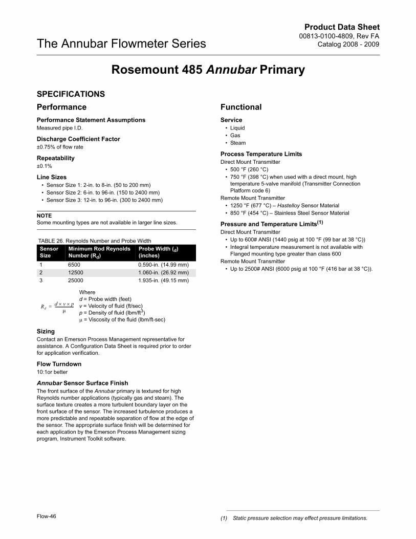
Product Data Sheet00813-0100-4809, Rev FA
Catalog 2008 - 2009The Annubar Flowmeter Series
Flow-46
Rosemount 485 Annubar Primary
SPECIFICATIONS
Performance
Performance Statement Assumptions
Measured pipe I.D.
Discharge Coefficient Factor
±0.75% of flow rate
Repeatability
±0.1%
Line Sizes
• Sensor Size 1: 2-in. to 8-in. (50 to 200 mm)
• Sensor Size 2: 6-in. to 96-in. (150 to 2400 mm)
• Sensor Size 3: 12-in. to 96-in. (300 to 2400 mm)
NOTE
Some mounting types are not available in larger line sizes.
TABLE 26. Reynolds Number and Probe Width
Sizing
Contact an Emerson Process Management representative for
assistance. A Configuration Data Sheet is required prior to order
for application verification.
Flow Turndown
10:1or better
Annubar Sensor Surface Finish
The front surface of the Annubar primary is textured for high
Reynolds number applications (typically gas and steam). The
surface texture creates a more turbulent boundary layer on the
front surface of the sensor. The increased turbulence produces a
more predictable and repeatable separation of flow at the edge of
the sensor. The appropriate surface finish will be determined for
each application by the Emerson Process Management sizing
program, Instrument Toolkit software.
Functional
Service
• Liquid
• Gas
• Steam
Process Temperature Limits
Direct Mount Transmitter
• 500 °F (260 °C)
• 750 °F (398 °C) when used with a direct mount, high
temperature 5-valve manifold (Transmitter Connection
Platform code 6)
Remote Mount Transmitter
• 1250 °F (677 °C) – Hastelloy Sensor Material
• 850 °F (454 °C) – Stainless Steel Sensor Material
Pressure and Temperature Limits(1)
Direct Mount Transmitter
• Up to 600# ANSI (1440 psig at 100 °F (99 bar at 38 °C))
• Integral temperature measurement is not available with
Flanged mounting type greater than class 600
Remote Mount Transmitter
• Up to 2500# ANSI (6000 psig at 100 °F (416 bar at 38 °C)).
Sensor
Size
Minimum Rod Reynolds
Number (Rd)
Probe Width (d)
(inches)
1 6500 0.590-in. (14.99 mm)
2 12500 1.060-in. (26.92 mm)
3 25000 1.935-in. (49.15 mm)
Where
d = Probe width (feet)
v = Velocity of fluid (ft/sec)
p = Density of fluid (lbm/ft3)
μ = Viscosity of the fluid (lbm/ft-sec)
Rd
d v× p×
μ---------------------=
(1) Static pressure selection may effect pressure limitations.
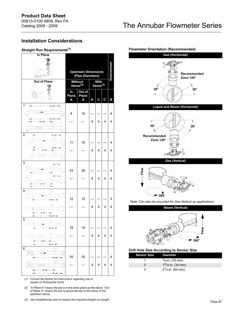
Product Data Sheet00813-0100-4809, Rev FA
Catalog 2008 - 2009 The Annubar Flowmeter Series
Flow-47
Installation Considerations
Drill Hole Size According to Sensor Size
Straight Run Requirements(1)
(1) Consult the factory for instructions regarding use in square or rectangular ducts.
Upstream Dimensions
(Pipe Diameters)
Do
wn
str
ea
m
Without
Vanes(2)
(2) “In Plane A” means the bar is in the same plane as the elbow. “Out of Plane A” means the bar is perpendicular to the plane of the upstream elbow.
With
Vanes(3)
(3) Use straightening vane to reduce the required straight run length.
In
Plane
A
Out of
Plane
A A’ C C’ B
1
8
—
10
—
—
8
—
4
—
4
4
4
2
11
—
16
—
—
8
—
4
—
4
4
4
3
23
—
28
—
—
8
—
4
—
4
4
4
4
12
—
12
—
—
8
—
4
—
4
4
4
5
18
—
18
—
—
8
—
4
—
4
4
4
6
30
—
30
—
—
8
—
4
—
4
4
4
Flowmeter Orientation (Recommended)
Gas (Horizontal)
Liquid and Steam (Horizontal)
Gas (Vertical)
Steam (Vertical)
Sensor Size Diameter
1 3/4-in. (19 mm)
2 15/16-in. (34 mm)
3 21/2-in. (64 mm)
30° 30°
Recommended
Zone 120°
30° 30°
Recommended
Zone 120°F
low
360°
Note: Can also be mounted for Gas Vertical up applications.
360°
Flo
w
In Plane
Out of Plane
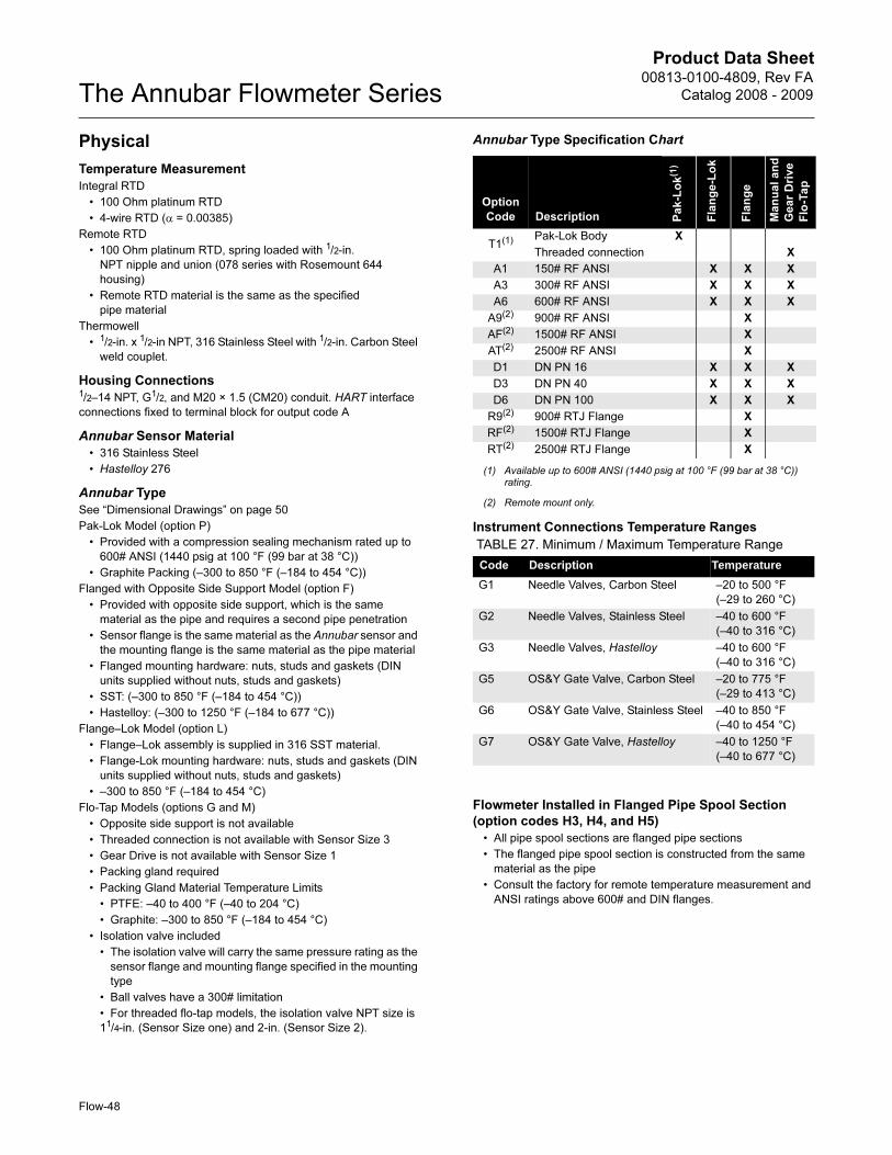
Product Data Sheet00813-0100-4809, Rev FA
Catalog 2008 - 2009The Annubar Flowmeter Series
Flow-48
Physical
Temperature Measurement
Integral RTD
• 100 Ohm platinum RTD
• 4-wire RTD (α = 0.00385)
Remote RTD
• 100 Ohm platinum RTD, spring loaded with 1/2-in.
NPT nipple and union (078 series with Rosemount 644
housing)
• Remote RTD material is the same as the specified
pipe material
Thermowell
• 1/2-in. x 1/2-in NPT, 316 Stainless Steel with 1/2-in. Carbon Steel
weld couplet.
Housing Connections1/2–14 NPT, G1/2, and M20 × 1.5 (CM20) conduit. HART interface
connections fixed to terminal block for output code A
Annubar Sensor Material
• 316 Stainless Steel
• Hastelloy 276
Annubar Type
See “Dimensional Drawings” on page 50
Pak-Lok Model (option P)
• Provided with a compression sealing mechanism rated up to
600# ANSI (1440 psig at 100 °F (99 bar at 38 °C))
• Graphite Packing (–300 to 850 °F (–184 to 454 °C))
Flanged with Opposite Side Support Model (option F)
• Provided with opposite side support, which is the same
material as the pipe and requires a second pipe penetration
• Sensor flange is the same material as the Annubar sensor and
the mounting flange is the same material as the pipe material
• Flanged mounting hardware: nuts, studs and gaskets (DIN
units supplied without nuts, studs and gaskets)
• SST: (–300 to 850 °F (–184 to 454 °C))
• Hastelloy: (–300 to 1250 °F (–184 to 677 °C))
Flange–Lok Model (option L)
• Flange–Lok assembly is supplied in 316 SST material.
• Flange-Lok mounting hardware: nuts, studs and gaskets (DIN
units supplied without nuts, studs and gaskets)
• –300 to 850 °F (–184 to 454 °C)
Flo-Tap Models (options G and M)
• Opposite side support is not available
• Threaded connection is not available with Sensor Size 3
• Gear Drive is not available with Sensor Size 1
• Packing gland required
• Packing Gland Material Temperature Limits
• PTFE: –40 to 400 °F (–40 to 204 °C)
• Graphite: –300 to 850 °F (–184 to 454 °C)
• Isolation valve included
• The isolation valve will carry the same pressure rating as the
sensor flange and mounting flange specified in the mounting
type
• Ball valves have a 300# limitation
• For threaded flo-tap models, the isolation valve NPT size is
11/4-in. (Sensor Size one) and 2-in. (Sensor Size 2).
Annubar Type Specification Chart
Instrument Connections Temperature Ranges
Flowmeter Installed in Flanged Pipe Spool Section
(option codes H3, H4, and H5)
• All pipe spool sections are flanged pipe sections
• The flanged pipe spool section is constructed from the same
material as the pipe
• Consult the factory for remote temperature measurement and
ANSI ratings above 600# and DIN flanges.
Option
Code Description Pa
k-L
ok(1)
(1) Available up to 600# ANSI (1440 psig at 100 °F (99 bar at 38 °C)) rating.
Fla
ng
e-L
ok
Fla
ng
e
Ma
nu
al a
nd
Ge
ar
Dri
ve
Flo
-Ta
p
T1(1) Pak-Lok Body X
Threaded connection X
A1 150# RF ANSI X X X
A3 300# RF ANSI X X X
A6 600# RF ANSI X X X
A9(2)
(2) Remote mount only.
900# RF ANSI X
AF(2) 1500# RF ANSI X
AT(2) 2500# RF ANSI X
D1 DN PN 16 X X X
D3 DN PN 40 X X X
D6 DN PN 100 X X X
R9(2) 900# RTJ Flange X
RF(2) 1500# RTJ Flange X
RT(2) 2500# RTJ Flange X
TABLE 27. Minimum / Maximum Temperature Range
Code Description Temperature
G1 Needle Valves, Carbon Steel –20 to 500 °F
(–29 to 260 °C)
G2 Needle Valves, Stainless Steel –40 to 600 °F
(–40 to 316 °C)
G3 Needle Valves, Hastelloy –40 to 600 °F
(–40 to 316 °C)
G5 OS&Y Gate Valve, Carbon Steel –20 to 775 °F
(–29 to 413 °C)
G6 OS&Y Gate Valve, Stainless Steel –40 to 850 °F
(–40 to 454 °C)
G7 OS&Y Gate Valve, Hastelloy –40 to 1250 °F
(–40 to 677 °C)
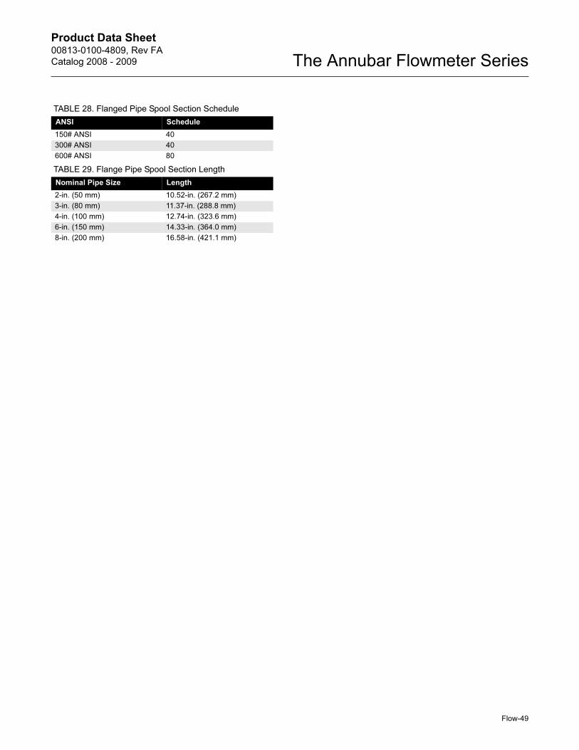
Product Data Sheet00813-0100-4809, Rev FA
Catalog 2008 - 2009 The Annubar Flowmeter Series
TABLE 28. Flanged Pipe Spool Section Schedule
ANSI Schedule
150# ANSI 40
300# ANSI 40
600# ANSI 80
TABLE 29. Flange Pipe Spool Section Length
Nominal Pipe Size Length
2-in. (50 mm) 10.52-in. (267.2 mm)
3-in. (80 mm) 11.37-in. (288.8 mm)
4-in. (100 mm) 12.74-in. (323.6 mm)
6-in. (150 mm) 14.33-in. (364.0 mm)
8-in. (200 mm) 16.58-in. (421.1 mm)
Flow-49
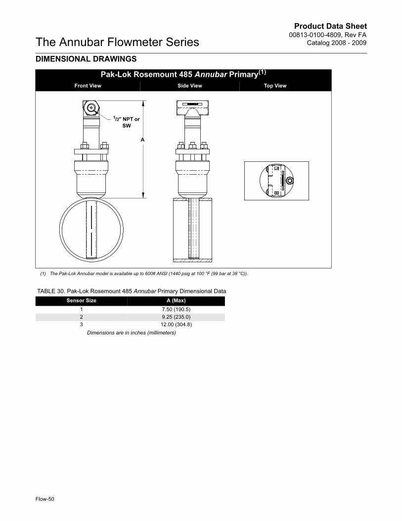
Product Data Sheet00813-0100-4809, Rev FA
Catalog 2008 - 2009The Annubar Flowmeter Series
Flow-50
DIMENSIONAL DRAWINGS
Pak-Lok Rosemount 485 Annubar Primary(1)
Front View Side View Top View_______
(1) The Pak-Lok Annubar model is available up to 600# ANSI (1440 psig at 100 °F (99 bar at 38 °C)).
A
1/2” NPT or
SW
TABLE 30. Pak-Lok Rosemount 485 Annubar Primary Dimensional Data
Sensor Size A (Max)
1 7.50 (190.5)
2 9.25 (235.0)
3 12.00 (304.8)
Dimensions are in inches (millimeters)
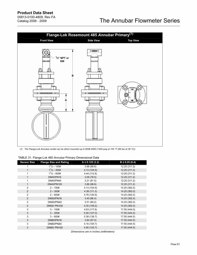
Product Data Sheet00813-0100-4809, Rev FA
Catalog 2008 - 2009 The Annubar Flowmeter Series
Flange-Lok Rosemount 485 Annubar Primary(1)
_____Front View Side View Top View__________
(1) The Flange-Lok Annubar model can be direct mounted up to 600# ANSI (1440 psig at 100 °F (99 bar at 38 °C)).
B
A
1/2” NPT or
SW
TABLE 31. Flange-Lok 485 Annubar Primary Dimensional Data
Sensor Size Flange Size and Rating A ± 0.125 (3.2) B ± 0.25 (6.4)
1 11/2 – 150# 3.88 (98.6) 12.25 (311.2)
1 11/2 – 300# 4.13 (104.9) 12.25 (311.2)
1 11/2 – 600# 4.44 (112.8) 12.25 (311.2)
1 DN40/PN16 3.09 (78.5) 12.25 (311.2)
1 DN40/PN40 3.21 (81.5) 12.25 (311.2)
1 DN40/PN100 3.88 (98.6) 12.25 (311.2)
2 2 – 150# 4.13 (104.9) 14.25 (362.0)
2 2 – 300# 4.38 (111.3) 14.25 (362.0)
2 2 – 600# 4.76 (120.9) 14.25 (362.0)
2 DN50/PN16 3.40 (86.4) 14.25 (362.0)
2 DN50/PN40 3.51 (89.2) 14.25 (362.0)
2 DN50/ PN100 4.30 (109.2) 14.25 (362.0)
3 3 – 150# 4.63 (117.6) 17.50 (444.5)
3 3 – 300# 5.00 (127.0) 17.50 (444.5)
3 3 – 600# 5.38 (136.7) 17.50 (444.5)
3 DN80/PN16 3.84 (97.5) 17.50 (444.5)
3 DN80/PN40 4.16 (105.7) 17.50 (444.5)
3 DN80/ PN100 4.95 (125.7) 17.50 (444.5)
Dimensions are in inches (millimeters)
Flow-51
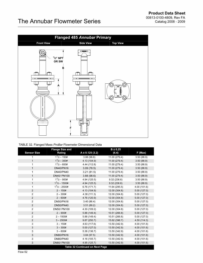
Product Data Sheet00813-0100-4809, Rev FA
Catalog 2008 - 2009The Annubar Flowmeter Series
Flow-52
Flanged 485 Annubar Primary
_____Front View Side View Top View_______________
B
A
F
1/2” NPT
OR SW
TABLE 32. Flanged Mass ProBar Flowmeter Dimensional Data
Sensor Size
Flange Size and
Rating A ± 0.125 (3.2)
B ± 0.25
(6.4) F (Max)
1 11/2 – 150# 3.88 (98.6) 11.00 (279.4) 3.50 (88.9)
1 11/2 – 300# 4.13 (104.9) 11.00 (279.4) 3.50 (88.9)
1 11/2 – 600# 4.44 (112.8) 11.00 (279.4) 3.50 (88.9)
1 DN40/PN16 3.09 (78.5) 11.00 (279.4) 3.50 (88.9)
1 DN40/PN40 3.21 (81.5) 11.00 (279.4) 3.50 (88.9)
1 DN40/ PN100 3.88 (98.6) 11.00 (279.4) 3.50 (88.9)
1 11/2 – 900# 4.94 (125.5) 9.32 (236.6) 3.50 (88.9)
1 11/2 – 1500# 4.94 (125.5) 9.32 (236.6) 3.50 (88.9)
1 11/2 – 2500# 6.76 (171.7) 11.64 (295.5) 4.00 (101.6)
2 2 – 150# 4.13 (104.9) 12.00 (304.8) 5.00 (127.0)
2 2 – 300# 4.38 (111.3) 12.00 (304.8) 5.00 (127.0)
2 2 – 600# 4.76 (120.9) 12.00 (304.8) 5.00 (127.0)
2 DN50/PN16 3.40 (86.4) 12.00 (304.8) 5.00 (127.0)
2 DN50/PN40 3.51 (89.2) 12.00 (304.8) 5.00 (127.0)
2 DN50/ PN100 4.30 (109.2) 12.00 (304.8) 5.00 (127.0)
2 2 – 900# 5.88 (149.4) 10.51 (266.8) 5.00 (127.0)
2 2 – 1500# 5.88 (149.4) 10.51 (266.8) 5.00 (127.0)
2 3 – 2500# 9.87 (250.7) 15.62 (396.7) 4.50 (114.3)
3 3 – 150# 4.63 (117.6) 13.50 (342.9) 4.00 (101.6)
3 3 – 300# 5.00 (127.0) 13.50 (342.9) 4.00 (101.6)
3 3 – 600# 5.38 (136.7) 13.50 (342.9) 4.00 (101.6)
3 DN80/PN16 3.84 (97.5) 13.50 (342.9) 4.00 (101.6)
3 DN80/PN40 4.16 (105.7) 13.50 (342.9) 4.00 (101.6)
3 DN80/ PN100 4.95 (125.7) 13.50 (342.9) 4.00 (101.6)
Table 32 Continued on Next Page

Product Data Sheet00813-0100-4809, Rev FA
Catalog 2008 - 2009 The Annubar Flowmeter Series
Flow-53
3 4 – 900# 8.19 (208.0) 13.44 (341.3) 7.00 (177.8)
3 4 – 1500# 8.56 (217.4) 13.81 (350.8) 7.00 (177.8)
3 4 – 2500# 11.19 (284.2) 17.32 (439.8) 7.00 (177.8)
Dimensions are in inches (millimeters)
TABLE 32. Flanged Mass ProBar Flowmeter Dimensional Data
Sensor Size
Flange Size and
Rating A ± 0.125 (3.2)
B ± 0.25
(6.4) F (Max)
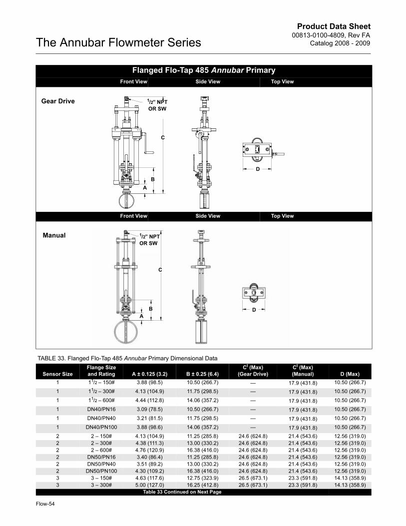
Product Data Sheet00813-0100-4809, Rev FA
Catalog 2008 - 2009The Annubar Flowmeter Series
Flanged Flo-Tap 485 Annubar Primary
Front View Side View Top View
Front View Side View Top View
Gear Drive
C
B
A
1/2” NPT
OR SW
D
C
B
A
Manual 1/2” NPT
OR SW
D
TABLE 33. Flanged Flo-Tap 485 Annubar Primary Dimensional Data
Sensor Size
Flange Size
and Rating A ± 0.125 (3.2) B ± 0.25 (6.4)
CI (Max)
(Gear Drive)
CI (Max)
(Manual) D (Max)
1 11/2 – 150# 3.88 (98.5) 10.50 (266.7) — 17.9 (431.8) 10.50 (266.7)
1 11/2 – 300# 4.13 (104.9) 11.75 (298.5) — 17.9 (431.8) 10.50 (266.7)
1 11/2 – 600# 4.44 (112.8) 14.06 (357.2) — 17.9 (431.8) 10.50 (266.7)
1 DN40/PN16 3.09 (78.5) 10.50 (266.7) — 17.9 (431.8) 10.50 (266.7)
1 DN40/PN40 3.21 (81.5) 11.75 (298.5) — 17.9 (431.8) 10.50 (266.7)
1 DN40/PN100 3.88 (98.6) 14.06 (357.2) — 17.9 (431.8) 10.50 (266.7)
2 2 – 150# 4.13 (104.9) 11.25 (285.8) 24.6 (624.8) 21.4 (543.6) 12.56 (319.0)
2 2 – 300# 4.38 (111.3) 13.00 (330.2) 24.6 (624.8) 21.4 (543.6) 12.56 (319.0)
2 2 – 600# 4.76 (120.9) 16.38 (416.0) 24.6 (624.8) 21.4 (543.6) 12.56 (319.0)
2 DN50/PN16 3.40 (86.4) 11.25 (285.8) 24.6 (624.8) 21.4 (543.6) 12.56 (319.0)
2 DN50/PN40 3.51 (89.2) 13.00 (330.2) 24.6 (624.8) 21.4 (543.6) 12.56 (319.0)
2 DN50/PN100 4.30 (109.2) 16.38 (416.0) 24.6 (624.8) 21.4 (543.6) 12.56 (319.0)
3 3 – 150# 4.63 (117.6) 12.75 (323.9) 26.5 (673.1) 23.3 (591.8) 14.13 (358.9)
3 3 – 300# 5.00 (127.0) 16.25 (412.8) 26.5 (673.1) 23.3 (591.8) 14.13 (358.9)
Table 33 Continued on Next Page
Flow-54
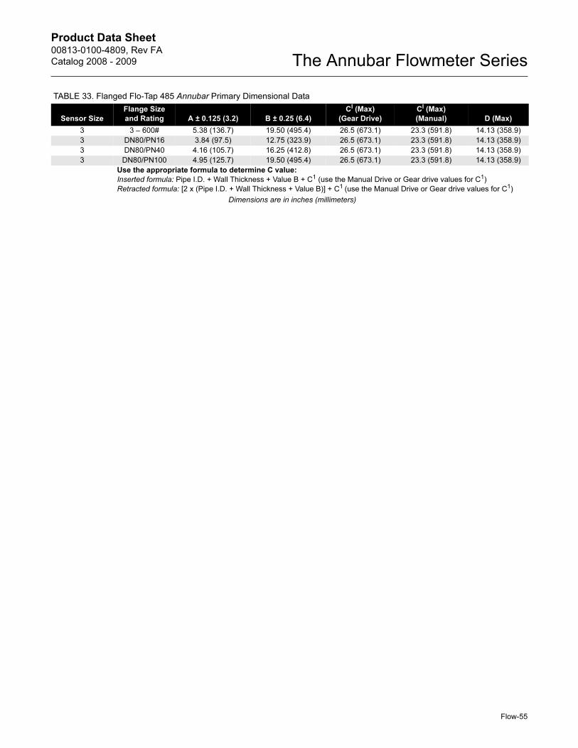
Product Data Sheet00813-0100-4809, Rev FA
Catalog 2008 - 2009 The Annubar Flowmeter Series
3 3 – 600# 5.38 (136.7) 19.50 (495.4) 26.5 (673.1) 23.3 (591.8) 14.13 (358.9)
3 DN80/PN16 3.84 (97.5) 12.75 (323.9) 26.5 (673.1) 23.3 (591.8) 14.13 (358.9)
3 DN80/PN40 4.16 (105.7) 16.25 (412.8) 26.5 (673.1) 23.3 (591.8) 14.13 (358.9)
3 DN80/PN100 4.95 (125.7) 19.50 (495.4) 26.5 (673.1) 23.3 (591.8) 14.13 (358.9)
Use the appropriate formula to determine C value:
Inserted formula: Pipe I.D. + Wall Thickness + Value B + C1 (use the Manual Drive or Gear drive values for C1)
Retracted formula: [2 x (Pipe I.D. + Wall Thickness + Value B)] + C1 (use the Manual Drive or Gear drive values for C1)
Dimensions are in inches (millimeters)
TABLE 33. Flanged Flo-Tap 485 Annubar Primary Dimensional Data
Sensor Size
Flange Size
and Rating A ± 0.125 (3.2) B ± 0.25 (6.4)
CI (Max)
(Gear Drive)
CI (Max)
(Manual) D (Max)
Flow-55
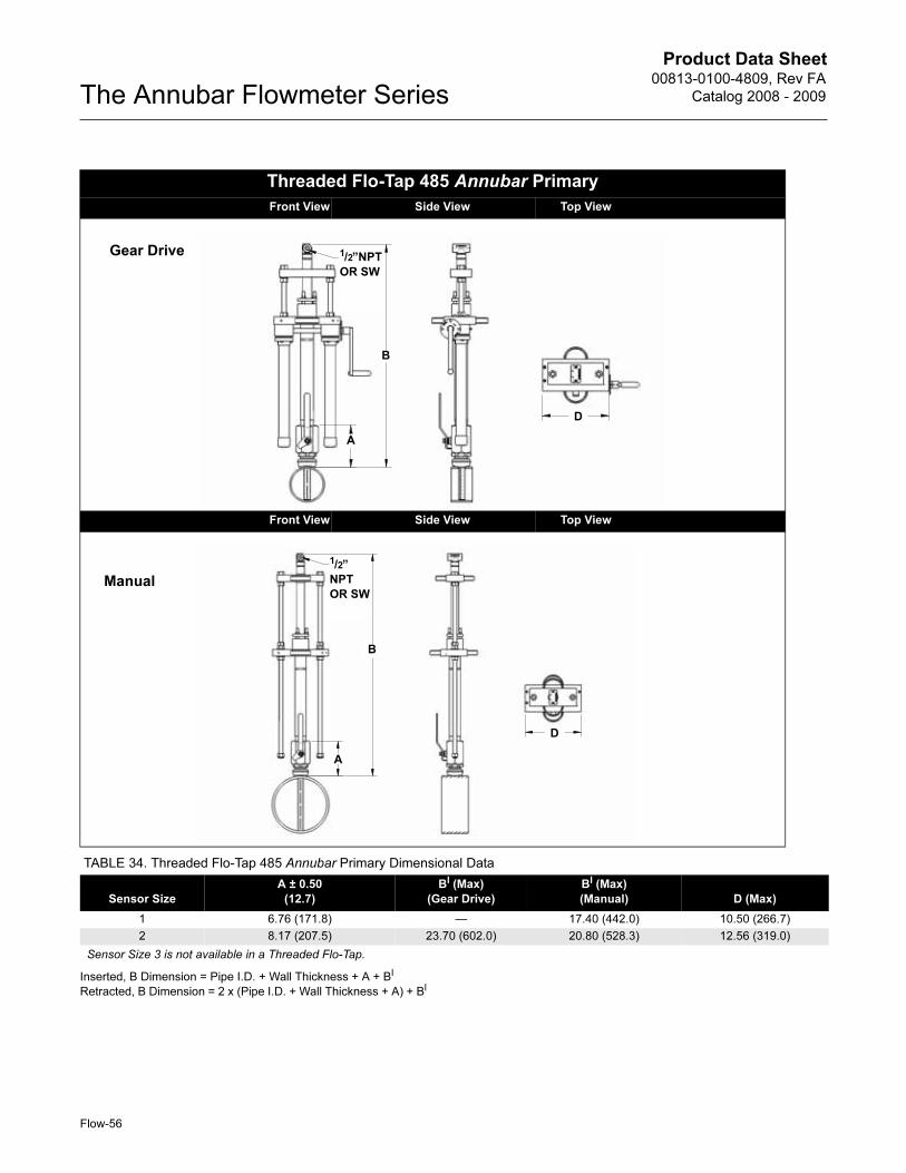
Product Data Sheet00813-0100-4809, Rev FA
Catalog 2008 - 2009The Annubar Flowmeter Series
Inserted, B Dimension = Pipe I.D. + Wall Thickness + A + BI
Retracted, B Dimension = 2 x (Pipe I.D. + Wall Thickness + A) + BI
Threaded Flo-Tap 485 Annubar Primary
Front View Side View Top View
Front View Side View Top View
TABLE 34. Threaded Flo-Tap 485 Annubar Primary Dimensional Data
Sensor Size
A ± 0.50
(12.7)
BI (Max)
(Gear Drive)
BI (Max)
(Manual) D (Max)
1 6.76 (171.8) — 17.40 (442.0) 10.50 (266.7)
2 8.17 (207.5) 23.70 (602.0) 20.80 (528.3) 12.56 (319.0)
Sensor Size 3 is not available in a Threaded Flo-Tap.
Gear Drive
B
1/2”NPT
OR SW
A
D
B
A
Manual
1/2”
NPT
OR SW
D
Flow-56
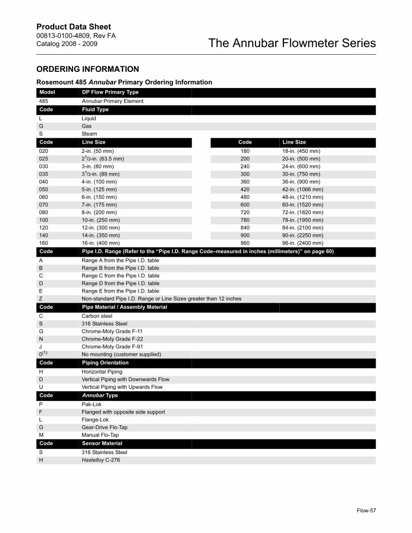
Product Data Sheet00813-0100-4809, Rev FA
Catalog 2008 - 2009 The Annubar Flowmeter Series
ORDERING INFORMATION
Rosemount 485 Annubar Primary Ordering Information
Model DP Flow Primary Type
485 Annubar Primary Element
Code Fluid Type
L Liquid
G Gas
S Steam
Code Line Size Code Line Size
020 2-in. (50 mm) 180 18-in. (450 mm)
025 21/2-in. (63.5 mm) 200 20-in. (500 mm)
030 3-in. (80 mm) 240 24-in. (600 mm)
035 31/2-in. (89 mm) 300 30-in. (750 mm)
040 4-in. (100 mm) 360 36-in. (900 mm)
050 5-in. (125 mm) 420 42-in. (1066 mm)
060 6-in. (150 mm) 480 48-in. (1210 mm)
070 7-in. (175 mm) 600 60-in. (1520 mm)
080 8-in. (200 mm) 720 72-in. (1820 mm)
100 10-in. (250 mm) 780 78-in. (1950 mm)
120 12-in. (300 mm) 840 84-in. (2100 mm)
140 14-in. (350 mm) 900 90-in. (2250 mm)
160 16-in. (400 mm) 960 96-in. (2400 mm)
Code Pipe I.D. Range (Refer to the “Pipe I.D. Range Code–measured in inches (millimeters)” on page 60)
A Range A from the Pipe I.D. table
B Range B from the Pipe I.D. table
C Range C from the Pipe I.D. table
D Range D from the Pipe I.D. table
E Range E from the Pipe I.D. table
Z Non-standard Pipe I.D. Range or Line Sizes greater than 12 inches
Code Pipe Material / Assembly Material
C Carbon steel
S 316 Stainless Steel
G Chrome-Moly Grade F-11
N Chrome-Moly Grade F-22
J Chrome-Moly Grade F-91
0(1) No mounting (customer supplied)
Code Piping Orientation
H Horizontal Piping
D Vertical Piping with Downwards Flow
U Vertical Piping with Upwards Flow
Code Annubar Type
P Pak-Lok
F Flanged with opposite side support
L Flange-Lok
G Gear-Drive Flo-Tap
M Manual Flo-Tap
Code Sensor Material
S 316 Stainless Steel
H Hastelloy C-276
Flow-57
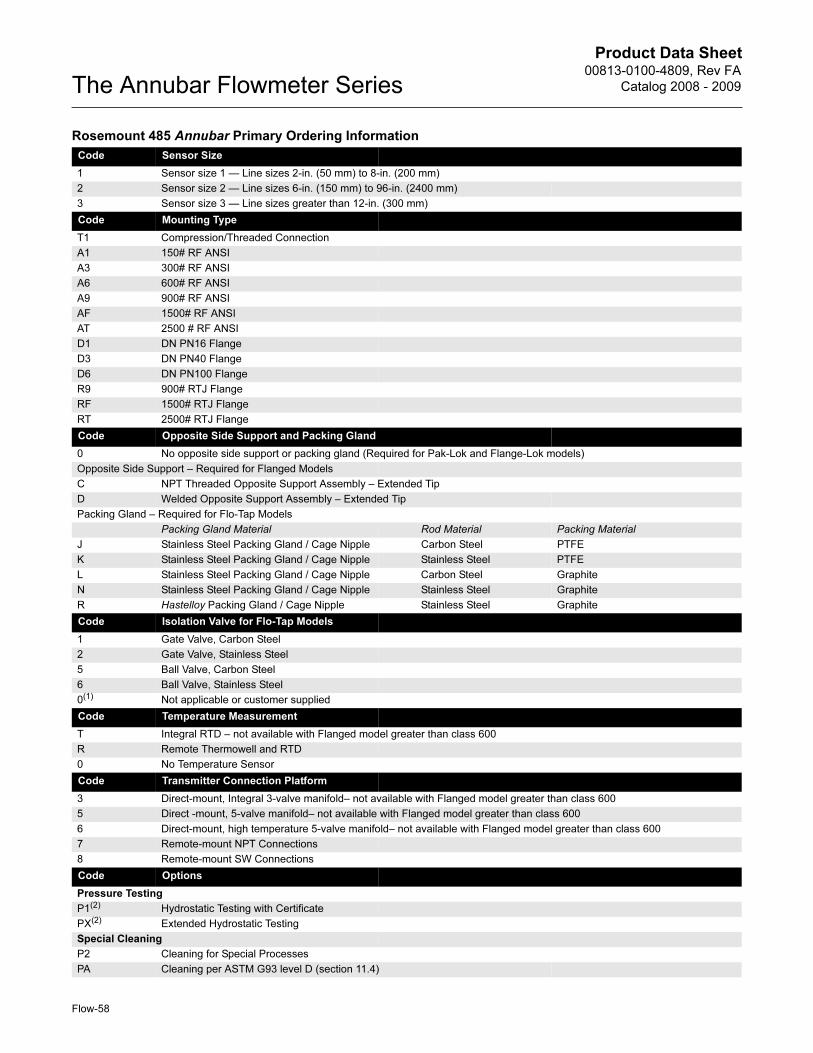
Product Data Sheet00813-0100-4809, Rev FA
Catalog 2008 - 2009The Annubar Flowmeter Series
Code Sensor Size
1 Sensor size 1 — Line sizes 2-in. (50 mm) to 8-in. (200 mm)
2 Sensor size 2 — Line sizes 6-in. (150 mm) to 96-in. (2400 mm)
3 Sensor size 3 — Line sizes greater than 12-in. (300 mm)
Code Mounting Type
T1 Compression/Threaded Connection
A1 150# RF ANSI
A3 300# RF ANSI
A6 600# RF ANSI
A9 900# RF ANSI
AF 1500# RF ANSI
AT 2500 # RF ANSI
D1 DN PN16 Flange
D3 DN PN40 Flange
D6 DN PN100 Flange
R9 900# RTJ Flange
RF 1500# RTJ Flange
RT 2500# RTJ Flange
Code Opposite Side Support and Packing Gland
0 No opposite side support or packing gland (Required for Pak-Lok and Flange-Lok models)
Opposite Side Support – Required for Flanged Models
C NPT Threaded Opposite Support Assembly – Extended Tip
D Welded Opposite Support Assembly – Extended Tip
Packing Gland – Required for Flo-Tap Models
Packing Gland Material Rod Material Packing Material
J Stainless Steel Packing Gland / Cage Nipple Carbon Steel PTFE
K Stainless Steel Packing Gland / Cage Nipple Stainless Steel PTFE
L Stainless Steel Packing Gland / Cage Nipple Carbon Steel Graphite
N Stainless Steel Packing Gland / Cage Nipple Stainless Steel Graphite
R Hastelloy Packing Gland / Cage Nipple Stainless Steel Graphite
Code Isolation Valve for Flo-Tap Models
1 Gate Valve, Carbon Steel
2 Gate Valve, Stainless Steel
5 Ball Valve, Carbon Steel
6 Ball Valve, Stainless Steel
0(1) Not applicable or customer supplied
Code Temperature Measurement
T Integral RTD – not available with Flanged model greater than class 600
R Remote Thermowell and RTD
0 No Temperature Sensor
Code Transmitter Connection Platform
3 Direct-mount, Integral 3-valve manifold– not available with Flanged model greater than class 600
5 Direct -mount, 5-valve manifold– not available with Flanged model greater than class 600
6 Direct-mount, high temperature 5-valve manifold– not available with Flanged model greater than class 600
7 Remote-mount NPT Connections
8 Remote-mount SW Connections
Code Options
Pressure Testing
P1(2) Hydrostatic Testing with Certificate
PX(2) Extended Hydrostatic Testing
Special Cleaning
P2 Cleaning for Special Processes
PA Cleaning per ASTM G93 level D (section 11.4)
Rosemount 485 Annubar Primary Ordering Information
Flow-58
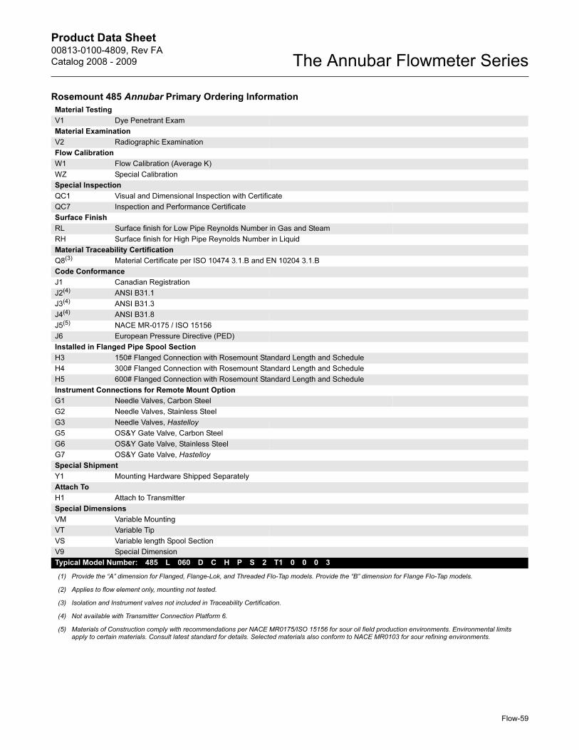
Product Data Sheet00813-0100-4809, Rev FA
Catalog 2008 - 2009 The Annubar Flowmeter Series
Material Testing
V1 Dye Penetrant Exam
Material Examination
V2 Radiographic Examination
Flow Calibration
W1 Flow Calibration (Average K)
WZ Special Calibration
Special Inspection
QC1 Visual and Dimensional Inspection with Certificate
QC7 Inspection and Performance Certificate
Surface Finish
RL Surface finish for Low Pipe Reynolds Number in Gas and Steam
RH Surface finish for High Pipe Reynolds Number in Liquid
Material Traceability Certification
Q8(3) Material Certificate per ISO 10474 3.1.B and EN 10204 3.1.B
Code Conformance
J1 Canadian Registration
J2(4) ANSI B31.1
J3(4) ANSI B31.3
J4(4) ANSI B31.8
J5(5) NACE MR-0175 / ISO 15156
J6 European Pressure Directive (PED)
Installed in Flanged Pipe Spool Section
H3 150# Flanged Connection with Rosemount Standard Length and Schedule
H4 300# Flanged Connection with Rosemount Standard Length and Schedule
H5 600# Flanged Connection with Rosemount Standard Length and Schedule
Instrument Connections for Remote Mount Option
G1 Needle Valves, Carbon Steel
G2 Needle Valves, Stainless Steel
G3 Needle Valves, Hastelloy
G5 OS&Y Gate Valve, Carbon Steel
G6 OS&Y Gate Valve, Stainless Steel
G7 OS&Y Gate Valve, Hastelloy
Special Shipment
Y1 Mounting Hardware Shipped Separately
Attach To
H1 Attach to Transmitter
Special Dimensions
VM Variable Mounting
VT Variable Tip
VS Variable length Spool Section
V9 Special Dimension
Typical Model Number: 485 L 060 D C H P S 2 T1 0 0 0 3
(1) Provide the “A” dimension for Flanged, Flange-Lok, and Threaded Flo-Tap models. Provide the “B” dimension for Flange Flo-Tap models.
(2) Applies to flow element only, mounting not tested.
(3) Isolation and Instrument valves not included in Traceability Certification.
(4) Not available with Transmitter Connection Platform 6.
(5) Materials of Construction comply with recommendations per NACE MR0175/ISO 15156 for sour oil field production environments. Environmental limits apply to certain materials. Consult latest standard for details. Selected materials also conform to NACE MR0103 for sour refining environments.
Rosemount 485 Annubar Primary Ordering Information
Flow-59
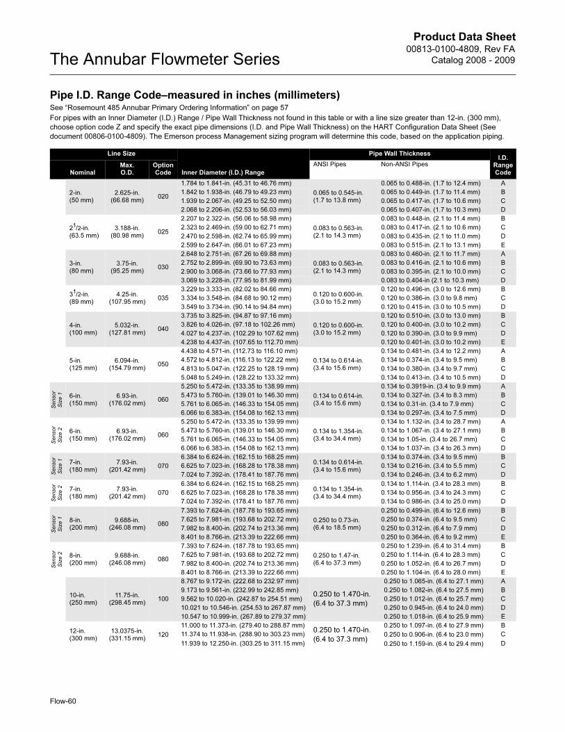
Product Data Sheet00813-0100-4809, Rev FA
Catalog 2008 - 2009The Annubar Flowmeter Series
Pipe I.D. Range Code–measured in inches (millimeters)See “Rosemount 485 Annubar Primary Ordering Information” on page 57
For pipes with an Inner Diameter (I.D.) Range / Pipe Wall Thickness not found in this table or with a line size greater than 12-in. (300 mm),
choose option code Z and specify the exact pipe dimensions (I.D. and Pipe Wall Thickness) on the HART Configuration Data Sheet (See
document 00806-0100-4809). The Emerson process Management sizing program will determine this code, based on the application piping.
Line Size
Inner Diameter (I.D.) Range
Pipe Wall ThicknessI.D.
Range CodeNominal
Max. O.D.
Option Code
ANSI Pipes Non-ANSI Pipes
2-in. (50 mm)
2.625-in. (66.68 mm)
020
1.784 to 1.841-in. (45.31 to 46.76 mm)
0.065 to 0.545-in. (1.7 to 13.8 mm)
0.065 to 0.488-in. (1.7 to 12.4 mm) A
1.842 to 1.938-in. (46.79 to 49.23 mm) 0.065 to 0.449-in. (1.7 to 11.4 mm) B
1.939 to 2.067-in. (49.25 to 52.50 mm) 0.065 to 0.417-in. (1.7 to 10.6 mm) C
2.068 to 2.206-in. (52.53 to 56.03 mm) 0.065 to 0.407-in. (1.7 to 10.3 mm) D
21/2-in. (63.5 mm)
3.188-in. (80.98 mm)
025
2.207 to 2.322-in. (56.06 to 58.98 mm)
0.083 to 0.563-in. (2.1 to 14.3 mm)
0.083 to 0.448-in. (2.1 to 11.4 mm) B
2.323 to 2.469-in. (59.00 to 62.71 mm) 0.083 to 0.417-in. (2.1 to 10.6 mm) C
2.470 to 2.598-in. (62.74 to 65.99 mm) 0.083 to 0.435-in. (2.1 to 11.0 mm) D
2.599 to 2.647-in. (66.01 to 67.23 mm) 0.083 to 0.515-in. (2.1 to 13.1 mm) E
3-in. (80 mm)
3.75-in. (95.25 mm)
030
2.648 to 2.751-in. (67.26 to 69.88 mm)
0.083 to 0.563-in. (2.1 to 14.3 mm)
0.083 to 0.460-in. (2.1 to 11.7 mm) A
2.752 to 2.899-in. (69.90 to 73.63 mm) 0.083 to 0.416-in. (2.1 to 10.6 mm) B
2.900 to 3.068-in. (73.66 to 77.93 mm) 0.083 to 0.395-in. (2.1 to 10.0 mm) C
3.069 to 3.228-in. (77.95 to 81.99 mm) 0.083 to 0.404-in (2.1 to 10.3 mm) D
31/2-in. (89 mm)
4.25-in. (107.95 mm)
035
3.229 to 3.333-in. (82.02 to 84.66 mm)0.120 to 0.600-in. (3.0 to 15.2 mm)
0.120 to 0.496-in. (3.0 to 12.6 mm) B
3.334 to 3.548-in. (84.68 to 90.12 mm) 0.120 to 0.386-in. (3.0 to 9.8 mm) C
3.549 to 3.734-in. (90.14 to 94.84 mm) 0.120 to 0.415-in. (3.0 to 10.5 mm) D
4-in. (100 mm)
5.032-in. (127.81 mm)
040
3.735 to 3.825-in. (94.87 to 97.16 mm)
0.120 to 0.600-in. (3.0 to 15.2 mm)
0.120 to 0.510-in. (3.0 to 13.0 mm) B
3.826 to 4.026-in. (97.18 to 102.26 mm) 0.120 to 0.400-in. (3.0 to 10.2 mm) C
4.027 to 4.237-in. (102.29 to 107.62 mm) 0.120 to 0.390-in. (3.0 to 9.9 mm) D
4.238 to 4.437-in. (107.65 to 112.70 mm) 0.120 to 0.401-in. (3.0 to 10.2 mm) E
5-in. (125 mm)
6.094-in. (154.79 mm)
050
4.438 to 4.571-in. (112.73 to 116.10 mm)
0.134 to 0.614-in. (3.4 to 15.6 mm)
0.134 to 0.481-in. (3.4 to 12.2 mm) A
4.572 to 4.812-in. (116.13 to 122.22 mm) 0.134 to 0.374-in. (3.4 to 9.5 mm) B
4.813 to 5.047-in. (122.25 to 128.19 mm) 0.134 to 0.380-in. (3.4 to 9.7 mm) C
5.048 to 5.249-in. (128.22 to 133.32 mm) 0.134 to 0.413-in. (3.4 to 10.5 mm) D
Sensor
Siz
e 1 6-in.
(150 mm)6.93-in.
(176.02 mm)060
5.250 to 5.472-in. (133.35 to 138.99 mm)
0.134 to 0.614-in. (3.4 to 15.6 mm)
0.134 to 0.3919-in. (3.4 to 9.9 mm) A
5.473 to 5.760-in. (139.01 to 146.30 mm) 0.134 to 0.327-in. (3.4 to 8.3 mm) B
5.761 to 6.065-in. (146.33 to 154.05 mm) 0.134 to 0.31-in. (3.4 to 7.9 mm) C
6.066 to 6.383-in. (154.08 to 162.13 mm) 0.134 to 0.297-in. (3.4 to 7.5 mm) D
Sensor
Siz
e 2 6-in.
(150 mm)6.93-in.
(176.02 mm)060
5.250 to 5.472-in. (133.35 to 139.99 mm)
0.134 to 1.354-in. (3.4 to 34.4 mm)
0.134 to 1.132-in. (3.4 to 28.7 mm) A
5.473 to 5.760-in. (139.01 to 146.30 mm) 0.134 to 1.067-in. (3.4 to 27.1 mm) B
5.761 to 6.065-in. (146.33 to 154.05 mm) 0.134 to 1.05-in. (3.4 to 26.7 mm) C
6.066 to 6.383-in. (154.08 to 162.13 mm) 0.134 to 1.037-in. (3.4 to 26.3 mm) D
Sensor
Siz
e 1 7-in.
(180 mm)7.93-in.
(201.42 mm)070
6.384 to 6.624-in. (162.15 to 168.25 mm)0.134 to 0.614-in. (3.4 to 15.6 mm)
0.134 to 0.374-in. (3.4 to 9.5 mm) B
6.625 to 7.023-in. (168.28 to 178.38 mm) 0.134 to 0.216-in. (3.4 to 5.5 mm) C
7.024 to 7.392-in. (178.41 to 187.76 mm) 0.134 to 0.246-in. (3.4 to 6.2 mm) D
Sensor
Siz
e 2 7-in.
(180 mm)7.93-in.
(201.42 mm)070
6.384 to 6.624-in. (162.15 to 168.25 mm)0.134 to 1.354-in. (3.4 to 34.4 mm)
0.134 to 1.114-in. (3.4 to 28.3 mm) B
6.625 to 7.023-in. (168.28 to 178.38 mm) 0.134 to 0.956-in. (3.4 to 24.3 mm) C
7.024 to 7.392-in. (178.41 to 187.76 mm) 0.134 to 0.986-in. (3.4 to 25.0 mm) D
Sensor
Siz
e 1 8-in.
(200 mm)9.688-in.
(246.08 mm)080
7.393 to 7.624-in. (187.78 to 193.65 mm)
0.250 to 0.73-in. (6.4 to 18.5 mm)
0.250 to 0.499-in. (6.4 to 12.6 mm) B
7.625 to 7.981-in. (193.68 to 202.72 mm) 0.250 to 0.374-in. (6.4 to 9.5 mm) C
7.982 to 8.400-in. (202.74 to 213.36 mm) 0.250 to 0.312-in. (6.4 to 7.9 mm) D
8.401 to 8.766-in. (213.39 to 222.66 mm) 0.250 to 0.364-in. (6.4 to 9.2 mm) E
Sensor
Siz
e 2 8-in.
(200 mm)9.688-in.
(246.08 mm)080
7.393 to 7.624-in. (187.78 to 193.65 mm)
0.250 to 1.47-in. (6.4 to 37.3 mm)
0.250 to 1.239-in. (6.4 to 31.4 mm) B
7.625 to 7.981-in. (193.68 to 202.72 mm) 0.250 to 1.114-in. (6.4 to 28.3 mm) C
7.982 to 8.400-in. (202.74 to 213.36 mm) 0.250 to 1.052-in. (6.4 to 26.7 mm) D
8.401 to 8.766-in. (213.39 to 222.66 mm) 0.250 to 1.104-in. (6.4 to 28.0 mm) E
10-in. (250 mm)
11.75-in. (298.45 mm)
100
8.767 to 9.172-in. (222.68 to 232.97 mm)
0.250 to 1.470-in.
(6.4 to 37.3 mm)
0.250 to 1.065-in. (6.4 to 27.1 mm) A
9.173 to 9.561-in. (232.99 to 242.85 mm) 0.250 to 1.082-in. (6.4 to 27.5 mm) B
9.562 to 10.020-in. (242.87 to 254.51 mm) 0.250 to 1.012-in. (6.4 to 25.7 mm) C
10.021 to 10.546-in. (254.53 to 267.87 mm) 0.250 to 0.945-in. (6.4 to 24.0 mm) D
10.547 to 10.999-in. (267.89 to 279.37 mm) 0.250 to 1.018-in. (6.4 to 25.9 mm) E
12-in. (300 mm)
13.0375-in. (331.15 mm)
120
11.000 to 11.373-in. (279.40 to 288.87 mm)0.250 to 1.470-in.
(6.4 to 37.3 mm)
0.250 to 1.097-in. (6.4 to 27.9 mm) B
11.374 to 11.938-in. (288.90 to 303.23 mm) 0.250 to 0.906-in. (6.4 to 23.0 mm) C
11.939 to 12.250-in. (303.25 to 311.15 mm) 0.250 to 1.159-in. (6.4 to 29.4 mm) D
Flow-60

Product Data Sheet00813-0100-4809, Rev FA
Catalog 2008 - 2009 The Annubar Flowmeter Series
Flow-61
Product Data Sheet00813-0100-4809, Rev FA
Catalog 2008 - 2009The Annubar Flowmeter Series
Standard Terms and Conditions of Sale can be found at www.rosemount.com\terms_of_saleThe Emerson logo is a trade mark and service mark of Emerson Electric Co. Rosemount, the Rosemount logotype, ProBar, Mass ProBar and Annubar are registered trademarks of Rosemount Inc. MultiVariable (MV), Coplanar, SuperModules, and Tri-Loop are trademarks of Rosemount Inc. Inconel is a trademark of International Nickel Co. Hastelloy is a registered trademark of Haynes International. HART is a registered trademark of the HART Communication Foundation. FOUNDATION is a trademark of the Fieldbus Foundation. All other marks are the property of their respective owners.
Emerson Process Management
© 2008 Rosemount Inc. All rights reserved.
¢00813-0100-4809M¤
Emerson Process Management Heath PlaceBognor RegisWest Sussex PO22 9SHEnglandT 44 (0) 1243 863121F 44 (0) 1243 867554
Emerson Process Management Asia Pacific Private Limited1 Pandan CrescentSingapore 128461T (65) 6777 8211F (65) 6777 [email protected]
Rosemount Inc.8200 Market BoulevardChanhassen, MN 55317 USAT (U.S.) 1-800-999-9307T (International) (952) 906-8888F (952) 949-7001
www.rosemount.com