Embed Size (px)
Citation preview

Product Data SheetSeptember 2014
00813-0100-4088, Rev AA
Rosemount 4088 MultiVariable™ Transmitter
With the innovative Rosemount 4088 MultiVariable Transmitter, you can maximize your measurement accuracy and output efficiency, not only today but over the life of your equipment. This versatile device provides a reliable, stable signal so you can achieve unmatched data accuracy and more effectively manage changing conditions to optimize profits. Because the 4088 is easy to configure and calibrate, you can more quickly install new measurement points, reducing the time it takes to get up and running. It requires minimal maintenance over time, so your crews can focus on optimizing other aspects of your operation. When issues do arise, Emerson experts are readily available with fast, thorough support so you can get back to what you do best – producing and maximizing profit.
Rosemount 4088 September 2014
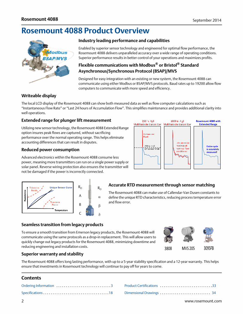
Rosemount 4088 Product OverviewIndustry leading performance and capabilities
Enabled by superior sensor technology and engineered for optimal flow performance, the Rosemount 4088 delivers unparalleled accuracy over a wide range of operating conditions. Superior performance results in better control of your operations and maximizes profits.
Flexible communications with Modbus® or Bristol® Standard Asynchronous/Synchronous Protocol (BSAP)/MVS
Designed for easy integration with an existing or new system, the Rosemount 4088 can communicate using either Modbus or BSAP/MVS protocols. Baud rates up to 19200 allow flow computers to communicate with more speed and efficiency.
Writeable display
The local LCD display of the Rosemount 4088 can show both measured data as well as flow computer calculations such as “Instantaneous Flow Rate” or “Last 24 hours of Accumulation Flow”. This simplifies maintenance and provides additional clarity into well operations.
Extended range for plunger lift measurement
Utilizing new sensor technology, the Rosemount 4088 Extended Range option insures peak flows are captured, without sacrificing performance over the normal operating range. This helps eliminate accounting differences that can result in disputes.
Reduced power consumption
Advanced electronics within the Rosemount 4088 consume less power, meaning more transmitters can run on a single power supply or solar panel. Reverse wiring protection also ensures the transmitter will not be damaged if the power is incorrectly connected.
Accurate RTD measurement through sensor matching
The Rosemount 4088 can make use of Callendar-Van Dusen constants to define the unique RTD characteristics, reducing process temperature error and flow error.
Seamless transition from legacy products
To ensure a smooth transition from Emerson legacy products, the Rosemount 4088 will communicate using the same protocols as a drop-in replacement. This will allow users to quickly change out legacy products for the Rosemount 4088, minimizing downtime and reducing engineering and installation costs.
Superior warranty and stability
The Rosemount 4088 offers long lasting performance, with up to a 5-year stability specification and a 12-year warranty. This helps ensure that investments in Rosemount technology will continue to pay off for years to come.
Contents
Ordering Information . . . . . . . . . . . . . . . . . . . . . . . . . . . . . 3
Specifications . . . . . . . . . . . . . . . . . . . . . . . . . . . . . . . . . . .18
Product Certifications . . . . . . . . . . . . . . . . . . . . . . . . . . . .33
Dimensional Drawings . . . . . . . . . . . . . . . . . . . . . . . . . . . 34
RO
A
B
C
RO
α
β
δ
2 www.rosemount.com
Rosemount 4088September 2014
Ordering InformationSpecification and selection of product materials, options, or components must be made by the purchaser of the equipment. See page 30 for more information on Material Selection.
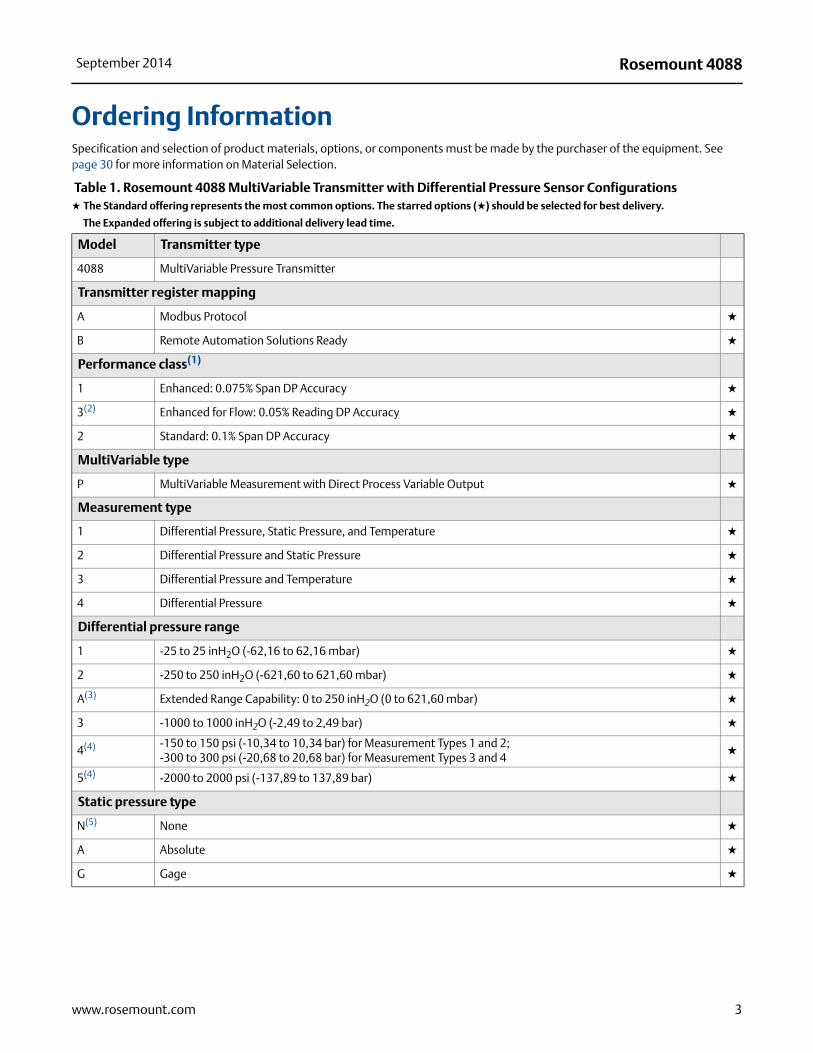
Table 1. Rosemount 4088 MultiVariable Transmitter with Differential Pressure Sensor Configurations★ The Standard offering represents the most common options. The starred options (★) should be selected for best delivery.
__The Expanded offering is subject to additional delivery lead time.
Model Transmitter type
4088 MultiVariable Pressure Transmitter
Transmitter register mapping
A Modbus Protocol ★
B Remote Automation Solutions Ready ★
Performance class(1)
1 Enhanced: 0.075% Span DP Accuracy ★
3(2) Enhanced for Flow: 0.05% Reading DP Accuracy ★
2 Standard: 0.1% Span DP Accuracy ★
MultiVariable type
P MultiVariable Measurement with Direct Process Variable Output ★
Measurement type
1 Differential Pressure, Static Pressure, and Temperature ★
2 Differential Pressure and Static Pressure ★
3 Differential Pressure and Temperature ★
4 Differential Pressure ★
Differential pressure range
1 -25 to 25 inH2O (-62,16 to 62,16 mbar) ★
2 -250 to 250 inH2O (-621,60 to 621,60 mbar) ★
A(3) Extended Range Capability: 0 to 250 inH2O (0 to 621,60 mbar) ★
3 -1000 to 1000 inH2O (-2,49 to 2,49 bar) ★
4(4) -150 to 150 psi (-10,34 to 10,34 bar) for Measurement Types 1 and 2; -300 to 300 psi (-20,68 to 20,68 bar) for Measurement Types 3 and 4
★
5(4) -2000 to 2000 psi (-137,89 to 137,89 bar) ★
Static pressure type
N(5) None ★
A Absolute ★
G Gage ★
3www.rosemount.com
Rosemount 4088 September 2014
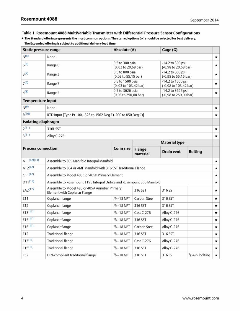
Static pressure range Absolute (A) Gage (G)
N(5) None ★
6(6) Range 60.5 to 300 psia (0, 03 to 20,68 bar)
-14.2 to 300 psi (-0,98 to 20,68 bar)
★
3(7) Range 30.5 to 800 psia (0,03 to 55,15 bar)
-14.2 to 800 psi (-0,98 to 55,15 bar)
★
7(6) Range 70.5 to 1500 psia (0, 03 to 103,42 bar)
-14.2 to 1500 psi (-0,98 to 103,42 bar)
★
4(8) Range 40.5 to 3626 psia (0,03 to 250,00 bar)
-14.2 to 3626 psi (-0,98 to 250,00 bar)
★
Temperature input
N(9) None ★
R(10) RTD Input [Type Pt 100, -328 to 1562 Deg F (-200 to 850 Deg C)] ★
Isolating diaphragm
2(11) 316L SST ★
3(11) Alloy C-276 ★
Process connection Conn size
Material type
Flange material
Drain vent Bolting
A11(12)(13) Assemble to 305 Manifold Integral Manifold ★
A12(12) Assemble to 304 or AMF Manifold with 316 SST Traditional Flange ★
C11(12) Assemble to Model 405C or 405P Primary Element ★
D11(12) Assemble to Rosemount 1195 Integral Orifice and Rosemount 305 Manifold ★
EA2(12) Assemble to Model 485 or 405A Annubar Primary Element with Coplanar Flange
316 SST 316 SST ★
E11 Coplanar flange 1/4–18 NPT Carbon Steel 316 SST ★
E12 Coplanar flange 1/4–18 NPT 316 SST 316 SST ★
E13(11) Coplanar flange 1/4–18 NPT Cast C-276 Alloy C-276 ★
E15(11) Coplanar flange 1/4–18 NPT 316 SST Alloy C-276 ★
E16(11) Coplanar flange 1/4–18 NPT Carbon Steel Alloy C-276 ★
F12 Traditional flange 1/4–18 NPT 316 SST 316 SST ★
F13(11) Traditional flange 1/4–18 NPT Cast C-276 Alloy C-276 ★
F15(11) Traditional flange 1/4–18 NPT 316 SST Alloy C-276 ★
F52 DIN-compliant traditional flange 1/4–18 NPT 316 SST 316 SST 7/16-in. bolting ★
Table 1. Rosemount 4088 MultiVariable Transmitter with Differential Pressure Sensor Configurations★ The Standard offering represents the most common options. The starred options (★) should be selected for best delivery.
__The Expanded offering is subject to additional delivery lead time.
4 www.rosemount.com
Rosemount 4088September 2014
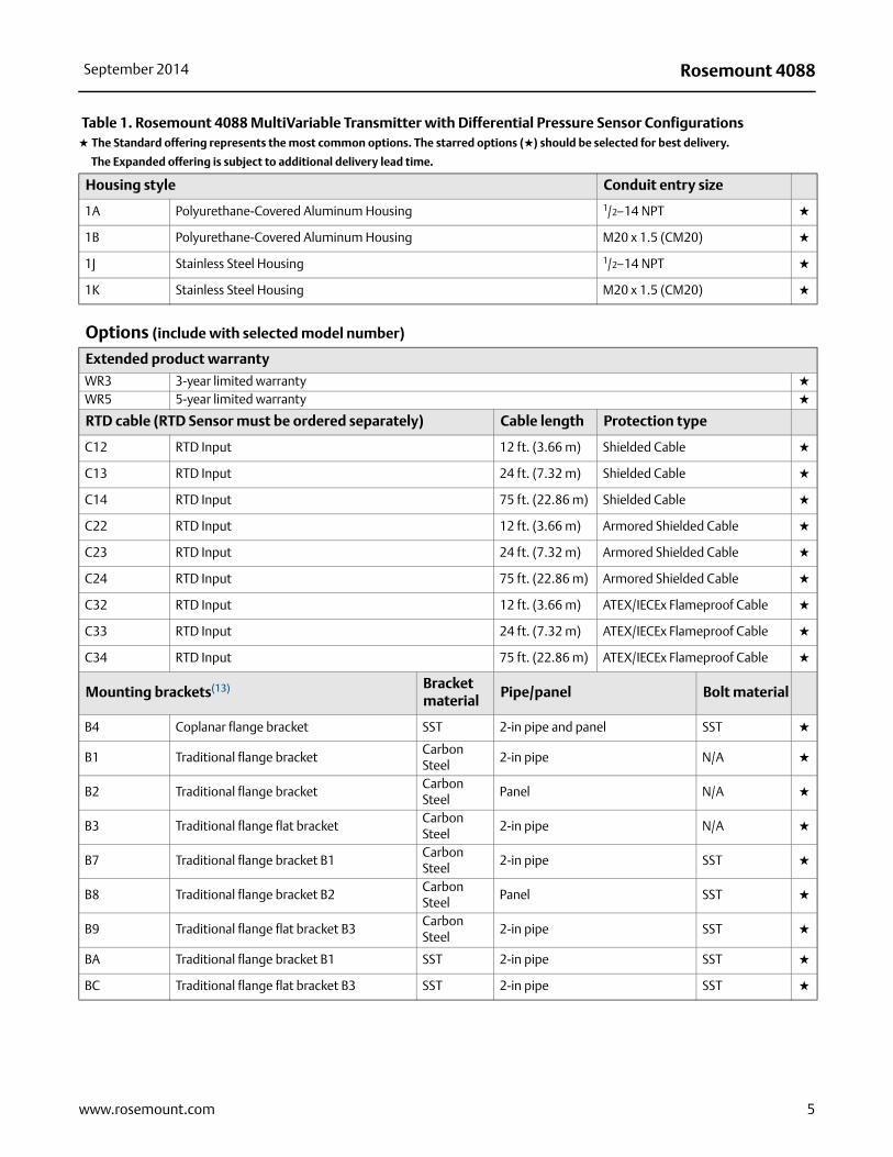
Housing style Conduit entry size
1A Polyurethane-Covered Aluminum Housing 1/2–14 NPT ★
1B Polyurethane-Covered Aluminum Housing M20 x 1.5 (CM20) ★
1J Stainless Steel Housing 1/2–14 NPT ★
1K Stainless Steel Housing M20 x 1.5 (CM20) ★
Options (include with selected model number)
Extended product warranty
WR3 3-year limited warranty ★
WR5 5-year limited warranty ★
RTD cable (RTD Sensor must be ordered separately) Cable length Protection type
C12 RTD Input 12 ft. (3.66 m) Shielded Cable ★
C13 RTD Input 24 ft. (7.32 m) Shielded Cable ★
C14 RTD Input 75 ft. (22.86 m) Shielded Cable ★
C22 RTD Input 12 ft. (3.66 m) Armored Shielded Cable ★
C23 RTD Input 24 ft. (7.32 m) Armored Shielded Cable ★
C24 RTD Input 75 ft. (22.86 m) Armored Shielded Cable ★
C32 RTD Input 12 ft. (3.66 m) ATEX/IECEx Flameproof Cable ★
C33 RTD Input 24 ft. (7.32 m) ATEX/IECEx Flameproof Cable ★
C34 RTD Input 75 ft. (22.86 m) ATEX/IECEx Flameproof Cable ★
Mounting brackets(13) Bracket material
Pipe/panel Bolt material
B4 Coplanar flange bracket SST 2-in pipe and panel SST ★
B1 Traditional flange bracketCarbon Steel
2-in pipe N/A ★
B2 Traditional flange bracketCarbon Steel
Panel N/A ★
B3 Traditional flange flat bracketCarbon Steel
2-in pipe N/A ★
B7 Traditional flange bracket B1Carbon Steel
2-in pipe SST ★
B8 Traditional flange bracket B2Carbon Steel
Panel SST ★
B9 Traditional flange flat bracket B3Carbon Steel
2-in pipe SST ★
BA Traditional flange bracket B1 SST 2-in pipe SST ★
BC Traditional flange flat bracket B3 SST 2-in pipe SST ★
Table 1. Rosemount 4088 MultiVariable Transmitter with Differential Pressure Sensor Configurations★ The Standard offering represents the most common options. The starred options (★) should be selected for best delivery.
__The Expanded offering is subject to additional delivery lead time.
5www.rosemount.com

Rosemount 4088 September 2014
Software configuration
C1(14) Custom software configuration Note: A Configuration Data Sheet must be completed.
★
Process adapters
D2 1/2–14 NPT process adapters ★
Custody transfer
D3 Measurement Canada Accuracy Approval ★
External ground screw assembly
D4(15)(15) External ground screw assembly ★
Drain/vent valve
D5(16) Delete transmitter drain/vent valves (install plugs) ★
Conduit plug
DO(17)(17) 316 SST Conduit Plug ★
Product certifications(19)
E1 ATEX Flameproof ★
I1 ATEX Intrinsic Safety ★
N1 ATEX Type n ★
ND ATEX Dust ★
K1 ATEX Flameproof, Intrinsic Safety, Type n, Dust (combination of E1, I1, N1, and ND) ★
E5 FM Explosion-proof, Dust Ignition-proof, Division 2 ★
I5 FM Intrinsically Safe, Division 2 ★
K5 FM Explosion-proof, Dust Ignition-proof, Intrinsically Safe, Division 2 (combination of E5 and I5) ★
E6(18) CSA Explosion-proof, Dust Ignition-proof, Division 2 ★
I6 CSA Intrinsically Safe ★
K6(18) CSA Explosion-proof, Dust Ignition-proof, Intrinsically Safe, Division 2 (combination of E6 and I6) ★
E7 IECEx Flameproof ★
I7 IECEx Intrinsic Safety ★
N7 IECEx Type n ★
K7 IECEx Flameproof, Intrinsic Safety, and Type n (combination of E7, I7, and N7) ★
E2 INMETRO Flameproof ★
I2 INMETRO Intrinsic Safety ★
K2 INMETRO Flameproof, Intrinsic Safety (combination of E2 and I2) ★
KA(18)(19) ATEX & CSA Explosion-proof, Intrinsically Safe, Division 2 (combination E1, E6, I1, and I6) ★
KB(18) FM & CSA Explosion-proof, Dust Ignition-proof, Intrinsically Safe, Division 2 (combination E5, I5, E6, and I6) ★
KC FM & ATEX Explosion-proof, Intrinsically Safe, Division 2 (combination E5, I5, E1, and I1) ★
KD(18) FM, CSA, & ATEX Explosion-proof, Intrinsically Safe (combination E5, E6, E1, I5, I6, and I1) ★
Table 1. Rosemount 4088 MultiVariable Transmitter with Differential Pressure Sensor Configurations★ The Standard offering represents the most common options. The starred options (★) should be selected for best delivery.
__The Expanded offering is subject to additional delivery lead time.
6 www.rosemount.com

Rosemount 4088September 2014
Sensor fill fluid
L1 Inert sensor fill fluid (Not available with an Absolute static pressure type) ★
O-ring
L2 Graphite-filled PTFE O-ring ★
Bolting material
L4 Austenitic 316 SST bolts ★
L5 ASTM A193, Grade B7M bolts ★
L6 Alloy K-500 bolts ★
L7 ASTM A453, Class D, Grade 660 bolts ★
L8 ASTM A193, Class 2, Grade B8M bolts ★
Digital display
M5 LCD Display ★
Pressure testing
P1 Hydrostatic testing with certificate ★
Cleaning process area
P2(16)(20) Cleaning for special services
P3(16) Cleaning for special services with testing for <1PPM chlorine/fluorine
Maximum static line pressure
P94500 psi (310 bar) static pressure limit Note: Requires Measurement Type 3 or 4
★
P06092 psi (420 bar) static pressure limitNote: Requires Measurement Type 3 or 4
★
Calibration data certification
Q4 Calibration certificate ★
QP Calibration certificate and tamper evident seal ★
Material traceability certification
Q8 Material traceability certification per EN 10204 3.1B ★
NACE certificates(20)
Q15 Certificate of Compliance to NACE MR0175/ISO15156 for wetted materials ★
Q25 Certificate of Compliance to NACE MR0103 for wetted materials ★
Terminal block
T1 Transient terminal block ★
Table 1. Rosemount 4088 MultiVariable Transmitter with Differential Pressure Sensor Configurations★ The Standard offering represents the most common options. The starred options (★) should be selected for best delivery.
__The Expanded offering is subject to additional delivery lead time.
7www.rosemount.com

Rosemount 4088 September 2014
Cold temperature
BRR -58 °F (-50 °C) Cold Temperature Start-up ★
Typical model numbers: 4088A1P12G7R2A111AC12C1K5M5Q4Q8T1,4088B1P12G7R2A111AC12C1K5Q4Q8T1
(1) For detailed specifications see "Performance specifications" Section on page 18.
(2) Performance Class 3 is only available with DP range 2, 3, and 4. DP Range 4 with Performance Class 3 is only available with Measurement Type 1 or 2.
(3) DP Range A is only available with Performance Class 1 and Measurement Types 1 and 2.
(4) Only available with static pressure ranges N and 4.
(5) Required for Measurement Types 3 and 4.
(6) SP Ranges 6 and 7 are only available with Measurement Types 1 or 2 and DP Range 2, 3, or A.
(7) Available with Measurement Types 1 and 2, DP Range 1, and Performance Class 1 or 2 only.
(8) Only available with Measurement Types 1 and 2. With DP range 1, absolute limits are 0.5 to 2000 psi (0,03 to 137,89 bar) and gage limits are -14.2 to 2000 psi (-0,98 to 137,89 bar).
(9) Required for Measurement Types 2 and 4.
(10) Required for Measurement Types 1 and 3. RTD Sensor must be ordered separately.
(11) Materials of Construction comply with metallurgical requirements highlighted within NACE MR0175/ISO 15156 for sour oil field production environments. Environmental limits apply to certain materials. Consult latest standard for details. Selected materials also conform to NACE MR0103 for sour refining environments. Order with Q15 or Q25 to receive a NACE certificate.
(12) “Assemble to” items are specified separately and require a completed model number
(13) For process connection option code A11, the mounting bracket must be ordered as part of the manifold model number.
(14) Not available for 4088B.
(15) This assembly is included with certification options E1, N1, K1, ND, E7, N7, K7, E2, K2, KA, KC, and KD.
(16) Not available with process connection option code A11.
(17) Transmitter is shipped with 316 SST conduit plug (uninstalled) in place of standard carbon steel conduit plug.
(18) Not available with M20 conduit entry size.
(19) Product certifications will not drive explosion-proof RTD cable fitting, glands, or adapters.
(20) NACE compliant wetted materials are identified by Footnote (11).
Table 1. Rosemount 4088 MultiVariable Transmitter with Differential Pressure Sensor Configurations★ The Standard offering represents the most common options. The starred options (★) should be selected for best delivery.
__The Expanded offering is subject to additional delivery lead time.
8 www.rosemount.com

Rosemount 4088September 2014
Specification and selection of product materials, options, or components must be made by the purchaser of the equipment. See page 30 for more information on Material Selection.
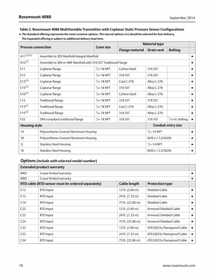
Table 2. Rosemount 4088 MultiVariable Transmitter with Coplanar Static Pressure Sensor Configurations★ The Standard offering represents the most common options. The starred options (★) should be selected for best delivery.
__The Expanded offering is subject to additional delivery lead time.
Model Transmitter type
4088 MultiVariable Pressure Transmitter
Transmitter register mapping
A Modbus Protocol ★
B Remote Automation Solutions Ready ★
Performance class(1)
1 Enhanced: 0.075% Span Accuracy ★
2 Standard: 0.1% Span Accuracy ★
MultiVariable type
P MultiVariable Measurement with Direct Process Variable Output ★
Measurement type
5 Static Pressure and Temperature - Coplanar Style ★
7 Static Pressure - Coplanar Style ★
Differential pressure range
N None ★
Static pressure type
A Absolute ★
G Gage ★
Static pressure range Absolute (A) Gage (G)
0 Range 0 0 to 5 psia (0 to 0,34 bar) N/A ★
1 Range 1 0 to 30 psia (0 to 2,06 bar)-25 to 25 inH2O (-62,16 to 62,16 mbar)
★
2 Range 2 0 to 150 psia (0 to 10,34 bar)-250 to 250 inH2O (-621,60 to 621,60 mbar)
★
3 Range 3 0 to 800 psia (0 to 55,15 bar)-393 to 1000 inH2O (-0,98 to 2,49 bar)
★
4 Range 4 0 to 4000 psia (0 to 275,79 bar)-14.2 to 300 psi (-0,98 to 20,68 bar)
★
5 Range 5 N/A-14.2 to 2000 psi (-0,98 to 137,89 bar)
★
Temperature input
N(2) None ★
R(3) RTD Input (Type Pt 100, -328 to 1562 Deg F [-200 to 850 Deg C)] ★
Isolating diaphragm
2(4) 316L SST ★
3(4) Alloy C-276 ★
9www.rosemount.com
Rosemount 4088 September 2014
Process connection Conn sizeMaterial type
Flange material Drain vent Bolting
A11(5)(6) Assemble to 305 Manifold Integral Manifold ★
A12(5) Assemble to 304 or AMF Manifold with 316 SST Traditional Flange ★
E11 Coplanar flange 1/4–18 NPT Carbon Steel 316 SST ★
E12 Coplanar flange 1/4–18 NPT 316 SST 316 SST ★
E13(4) Coplanar flange 1/4–18 NPT Cast C-276 Alloy C-276 ★
E15(4) Coplanar flange 1/4–18 NPT 316 SST Alloy C-276 ★
E16(4) Coplanar flange 1/4–18 NPT Carbon Steel Alloy C-276 ★
F12 Traditional flange 1/4–18 NPT 316 SST 316 SST ★
F13(4) Traditional flange 1/4–18 NPT Cast C-276 Alloy C-276 ★
F15(4) Traditional flange 1/4–18 NPT 316 SST Alloy C-276 ★
F52 DIN-compliant traditional flange 1/4–18 NPT 316 SST 316 SST 7/16-in. bolting ★
Housing style Conduit entry size
1A Polyurethane-Covered Aluminum Housing 1/2–14 NPT ★
1B Polyurethane-Covered Aluminum Housing M20 x 1.5 (CM20) ★
1J Stainless Steel Housing 1/2–14 NPT ★
1K Stainless Steel Housing M20 x 1.5 (CM20) ★
Options (include with selected model number)
Extended product warranty
WR3 3-year limited warranty ★
WR5 5-year limited warranty ★
RTD cable (RTD sensor must be ordered separately) Cable length Protection type
C12 RTD Input 12 ft. (3.66 m) Shielded Cable ★
C13 RTD Input 24 ft. (7.32 m) Shielded Cable ★
C14 RTD Input 75 ft. (22.86 m) Shielded Cable ★
C22 RTD Input 12 ft. (3.66 m) Armored Shielded Cable ★
C23 RTD Input 24 ft. (7.32 m) Armored Shielded Cable ★
C24 RTD Input 75 ft. (22.86 m) Armored Shielded Cable ★
C32 RTD Input 12 ft. (3.66 m) ATEX/IECEx Flameproof Cable ★
C33 RTD Input 24 ft. (7.32 m) ATEX/IECEx Flameproof Cable ★
C34 RTD Input 75 ft. (22.86 m) ATEX/IECEx Flameproof Cable ★
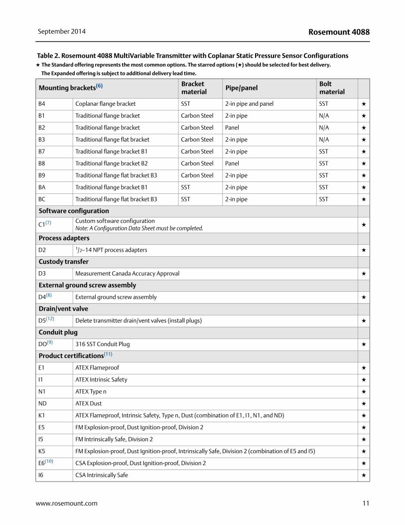
Table 2. Rosemount 4088 MultiVariable Transmitter with Coplanar Static Pressure Sensor Configurations★ The Standard offering represents the most common options. The starred options (★) should be selected for best delivery.
__The Expanded offering is subject to additional delivery lead time.
10 www.rosemount.com
Rosemount 4088September 2014
Mounting brackets(6) Bracket material
Pipe/panelBolt material
B4 Coplanar flange bracket SST 2-in pipe and panel SST ★
B1 Traditional flange bracket Carbon Steel 2-in pipe N/A ★
B2 Traditional flange bracket Carbon Steel Panel N/A ★
B3 Traditional flange flat bracket Carbon Steel 2-in pipe N/A ★
B7 Traditional flange bracket B1 Carbon Steel 2-in pipe SST ★
B8 Traditional flange bracket B2 Carbon Steel Panel SST ★
B9 Traditional flange flat bracket B3 Carbon Steel 2-in pipe SST ★
BA Traditional flange bracket B1 SST 2-in pipe SST ★
BC Traditional flange flat bracket B3 SST 2-in pipe SST ★
Software configuration
C1(7) Custom software configuration Note: A Configuration Data Sheet must be completed.
★
Process adapters
D2 1/2–14 NPT process adapters ★
Custody transfer
D3 Measurement Canada Accuracy Approval ★
External ground screw assembly
D4(8) External ground screw assembly ★
Drain/vent valve
D5(12) Delete transmitter drain/vent valves (install plugs) ★
Conduit plug
DO(9) 316 SST Conduit Plug ★
Product certifications(11)
E1 ATEX Flameproof ★
I1 ATEX Intrinsic Safety ★
N1 ATEX Type n ★
ND ATEX Dust ★
K1 ATEX Flameproof, Intrinsic Safety, Type n, Dust (combination of E1, I1, N1, and ND) ★
E5 FM Explosion-proof, Dust Ignition-proof, Division 2 ★
I5 FM Intrinsically Safe, Division 2 ★
K5 FM Explosion-proof, Dust Ignition-proof, Intrinsically Safe, Division 2 (combination of E5 and I5) ★
E6(10) CSA Explosion-proof, Dust Ignition-proof, Division 2 ★
I6 CSA Intrinsically Safe ★
Table 2. Rosemount 4088 MultiVariable Transmitter with Coplanar Static Pressure Sensor Configurations★ The Standard offering represents the most common options. The starred options (★) should be selected for best delivery.
__The Expanded offering is subject to additional delivery lead time.
11www.rosemount.com

Rosemount 4088 September 2014
K6(10) CSA Explosion-proof, Dust Ignition-proof, Intrinsically Safe, Division 2 (combination of E6 and I6) ★
E7 IECEx Flameproof ★
I7 IECEx Intrinsic Safety ★
N7 IECEx Type n ★
K7 IECEx Flameproof, Intrinsic Safety, and Type n (combination of E7, I7, and N7) ★
E2 INMETRO Flameproof ★
I2 INMETRO Intrinsic Safety ★
K2 INMETRO Flameproof, Intrinsic Safety (combination of E2 and I2) ★
KA(10)(11) ATEX & CSA Explosion-proof, Intrinsically Safe, Division 2 (combination E1, E6, I1, and I6) ★
KB(10) FM & CSA Explosion-proof, Dust Ignition-proof, Intrinsically Safe, Division 2 (combination E5, I5, E6, and I6) ★
KC FM & ATEX Explosion-proof, Intrinsically Safe, Division 2 (combination E5, I5, E1, and I1) ★
KD(10) FM, CSA, & ATEX Explosion-proof, Intrinsically Safe (combination E5, E6, E1, I5, I6, and I1) ★
Sensor fill fluid
L1 Inert sensor fill fluid (Not available with an Absolute static pressure type) ★
O-ring
L2 Graphite-filled PTFE O-ring ★
Bolting material
L4 Austenitic 316 SST bolts ★
L5 ASTM A193, Grade B7M bolts ★
L6 Alloy K-500 bolts ★
L7 ASTM A453, Class D, Grade 660 bolts ★
L8 ASTM A193, Class 2, Grade B8M bolts ★
Digital display
M5 LCD Display ★
Pressure testing
P1 Hydrostatic testing with certificate ★
Cleaning process area
P2(12)(12) Cleaning for special services
P3(12) Cleaning for special services with testing for <1PPM chlorine/fluorine
Calibration data certification
Q4 Calibration certificate ★
QP Calibration certificate and tamper evident seal ★
Material traceability certification
Q8 Material traceability certification per EN 10204 3.1B ★
Table 2. Rosemount 4088 MultiVariable Transmitter with Coplanar Static Pressure Sensor Configurations★ The Standard offering represents the most common options. The starred options (★) should be selected for best delivery.
__The Expanded offering is subject to additional delivery lead time.
12 www.rosemount.com
Rosemount 4088September 2014
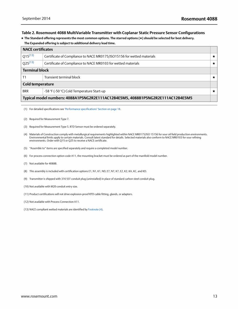
NACE certificates
Q15(13)(13) Certificate of Compliance to NACE MR0175/ISO15156 for wetted materials ★
Q25(13) Certificate of Compliance to NACE MR0103 for wetted materials ★
Terminal block
T1 Transient terminal block ★
Cold temperature
BRR -58 °F (-50 °C) Cold Temperature Start-up ★
Typical model numbers: 4088A1P5NG2R2E111AC12B4E5M5, 4088B1P5NG2R2E111AC12B4E5M5
(1) For detailed specifications see "Performance specifications" Section on page 18.
(2) Required for Measurement Type 7.
(3) Required for Measurement Type 5. RTD Sensor must be ordered separately.
(4) Materials of Construction comply with metallurgical requirements highlighted within NACE MR0175/ISO 15156 for sour oil field production environments. Environmental limits apply to certain materials. Consult latest standard for details. Selected materials also conform to NACE MR0103 for sour refining environments. Order with Q15 or Q25 to receive a NACE certificate.
(5) “Assemble to” items are specified separately and require a completed model number.
(6) For process connection option code A11, the mounting bracket must be ordered as part of the manifold model number.
(7) Not available for 4088B.
(8) This assembly is included with certification options E1, N1, K1, ND, E7, N7, K7, E2, K2, KA, KC, and KD.
(9) Transmitter is shipped with 316 SST conduit plug (uninstalled) in place of standard carbon steel conduit plug.
(10) Not available with M20 conduit entry size.
(11) Product certifications will not drive explosion-proof RTD cable fitting, glands, or adapters.
(12) Not available with Process Connection A11.
(13) NACE compliant wetted materials are identified by Footnote (4).
Table 2. Rosemount 4088 MultiVariable Transmitter with Coplanar Static Pressure Sensor Configurations★ The Standard offering represents the most common options. The starred options (★) should be selected for best delivery.
__The Expanded offering is subject to additional delivery lead time.
13www.rosemount.com

Rosemount 4088 September 2014
Specification and selection of product materials, options, or components must be made by the purchaser of the equipment. See page 30 for more information on Material Selection.
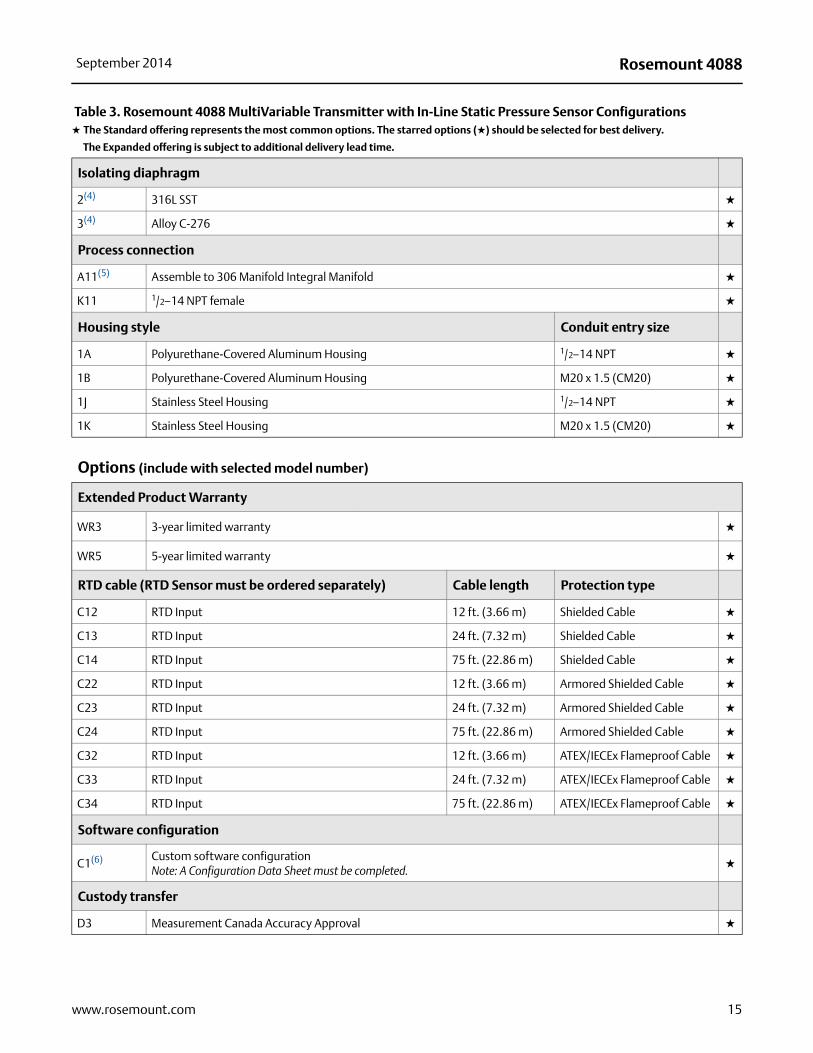
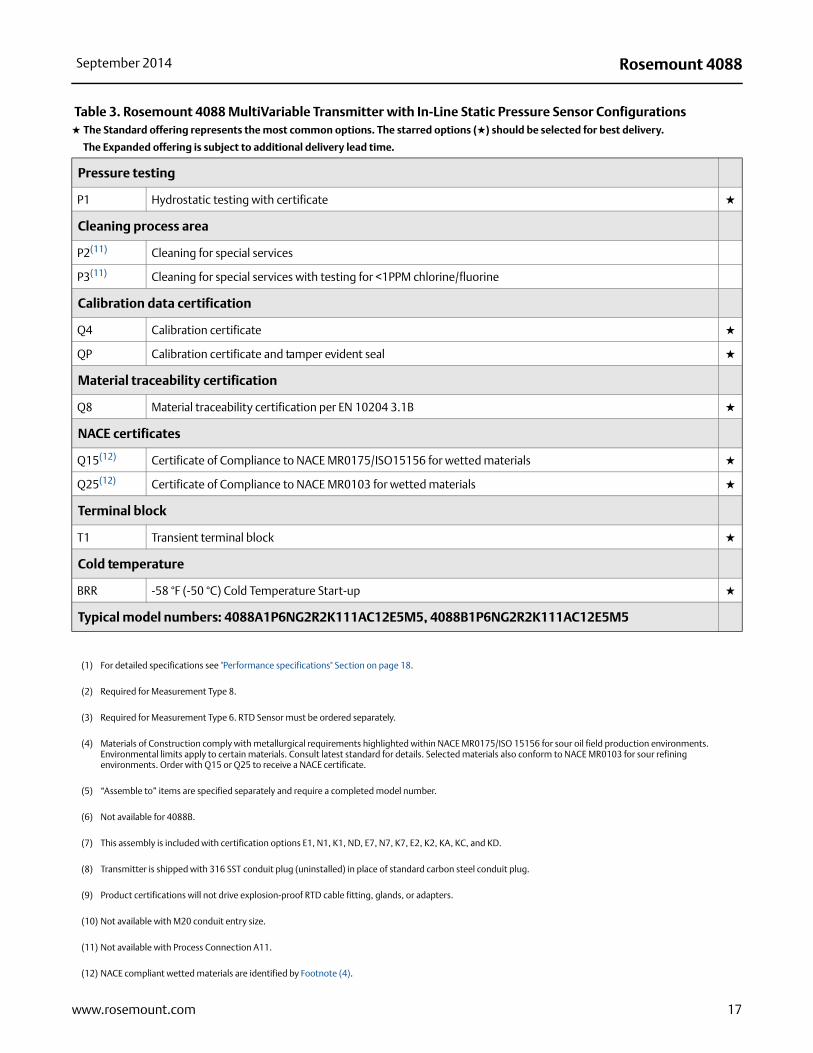
Table 3. Rosemount 4088 MultiVariable Transmitter with In-Line Static Pressure Sensor Configurations★ The Standard offering represents the most common options. The starred options (★) should be selected for best delivery.
__The Expanded offering is subject to additional delivery lead time.
Model Transmitter type
4088 MultiVariable Pressure Transmitter
Transmitter register mapping
A Modbus Protocol ★
B Remote Automation Solutions Ready ★
Performance class(1)
1 Enhanced: 0.075% Span Accuracy ★
2 Standard: 0.1% Span Accuracy ★
MultiVariable type
P MultiVariable Measurement with Direct Process Variable Output ★
Measurement type
6 Static Pressure and Temperature - In-line style ★
8 Static Pressure - In-Line Style ★
Differential pressure range
N None ★
Static pressure type
A Absolute ★
G Gage ★
Static pressure range Absolute (A) Gage (G)
1 Range 1 0 to 30 psia (0 to 2,06 bar)-14.7 to 30 psi (-1,01 to 2,06 bar)
★
2 Range 2 0 to 150 psia (0 to 10,34 bar)-14.7 to 150 psi (-1,01 to 10,34 bar)
★
3 Range 3 0 to 800 psia (0 to 55,15 bar)-14.7 to 800 psi (-1,01 to 55,15 bar)
★
4 Range 4 0 to 4000 psia (0 to 275,79 bar)-14.7 to 4000 psi (-1,01 to 275,79 bar)
★
5 Range 5 0 to 10000 psia (0 to 689,47 bar)-14.7 to 10000 psi (-1,01 to 689,47 bar)
★
Temperature input
N(2) None ★
R(3) RTD Input (Type Pt 100, -328 to 1562 Deg F (-200 to 850 Deg C)) ★
14 www.rosemount.com
Rosemount 4088September 2014
Isolating diaphragm
2(4)(4) 316L SST ★
3(4) Alloy C-276 ★
Process connection
A11(5) Assemble to 306 Manifold Integral Manifold ★
K11 1/2–14 NPT female ★
Housing style Conduit entry size
1A Polyurethane-Covered Aluminum Housing 1/2–14 NPT ★
1B Polyurethane-Covered Aluminum Housing M20 x 1.5 (CM20) ★
1J Stainless Steel Housing 1/2–14 NPT ★
1K Stainless Steel Housing M20 x 1.5 (CM20) ★
Options (include with selected model number)
Extended Product Warranty
WR3 3-year limited warranty ★
WR5 5-year limited warranty ★
RTD cable (RTD Sensor must be ordered separately) Cable length Protection type
C12 RTD Input 12 ft. (3.66 m) Shielded Cable ★
C13 RTD Input 24 ft. (7.32 m) Shielded Cable ★
C14 RTD Input 75 ft. (22.86 m) Shielded Cable ★
C22 RTD Input 12 ft. (3.66 m) Armored Shielded Cable ★
C23 RTD Input 24 ft. (7.32 m) Armored Shielded Cable ★
C24 RTD Input 75 ft. (22.86 m) Armored Shielded Cable ★
C32 RTD Input 12 ft. (3.66 m) ATEX/IECEx Flameproof Cable ★
C33 RTD Input 24 ft. (7.32 m) ATEX/IECEx Flameproof Cable ★
C34 RTD Input 75 ft. (22.86 m) ATEX/IECEx Flameproof Cable ★
Software configuration
C1(6) Custom software configuration Note: A Configuration Data Sheet must be completed.
★
Custody transfer
D3 Measurement Canada Accuracy Approval ★
Table 3. Rosemount 4088 MultiVariable Transmitter with In-Line Static Pressure Sensor Configurations★ The Standard offering represents the most common options. The starred options (★) should be selected for best delivery.
__The Expanded offering is subject to additional delivery lead time.
15www.rosemount.com

Rosemount 4088 September 2014
External ground screw assembly
D4(7) External ground screw assembly ★
Drain/vent valve
D5(11) Delete transmitter drain/vent valves (install plugs) ★
Conduit plug
DO(8) 316 SST Conduit Plug ★
Product certifications(9)
E1 ATEX Flameproof ★
I1 ATEX Intrinsic Safety ★
N1 ATEX Type n ★
ND ATEX Dust ★
K1 ATEX Flameproof, Intrinsic Safety, Type n, Dust (combination of E1, I1, N1, and ND) ★
E5 FM Explosion-proof, Dust Ignition-proof, Division 2 ★
I5 FM Intrinsically Safe, Division 2 ★
K5 FM Explosion-proof, Dust Ignition-proof, Intrinsically Safe, Division 2 (combination of E5 and I5) ★
E6(10) CSA Explosion-proof, Dust Ignition-proof, Division 2 ★
I6 CSA Intrinsically Safe ★
K6(10) CSA Explosion-proof, Dust Ignition-proof, Intrinsically Safe, Division 2 (combination of E6 and I6) ★
E7 IECEx Flameproof ★
I7 IECEx Intrinsic Safety ★
N7 IECEx Type n ★
K7 IECEx Flameproof, Intrinsic Safety, and Type n (combination of E7, I7, and N7) ★
E2 INMETRO Flameproof ★
I2 INMETRO Intrinsic Safety ★
K2 INMETRO Flameproof, Intrinsic Safety (combination of E2 and I2) ★
KA(10) ATEX & CSA Explosion-proof, Intrinsically Safe, Division 2 (combination E1, E6, I1, and I6) ★
KB(10) FM & CSA Explosion-proof, Dust Ignition-proof, Intrinsically Safe, Division 2 (combination E5, I5, E6, and I6) ★
KC FM & ATEX Explosion-proof, Intrinsically Safe, Division 2 (combination E5, I5, E1, and I1) ★
KD(10) FM, CSA, & ATEX Explosion-proof, Intrinsically Safe (combination E5, E6, E1, I5, I6, and I1) ★
Sensor fill fluid
L1 Inert sensor fill fluid (Not available with an Absolute static pressure type) ★
Digital display
M5 LCD Display ★
Table 3. Rosemount 4088 MultiVariable Transmitter with In-Line Static Pressure Sensor Configurations★ The Standard offering represents the most common options. The starred options (★) should be selected for best delivery.
__The Expanded offering is subject to additional delivery lead time.
16 www.rosemount.com
Rosemount 4088September 2014
Pressure testing
P1 Hydrostatic testing with certificate ★
Cleaning process area
P2(11) Cleaning for special services
P3(11) Cleaning for special services with testing for <1PPM chlorine/fluorine
Calibration data certification
Q4 Calibration certificate ★
QP Calibration certificate and tamper evident seal ★
Material traceability certification
Q8 Material traceability certification per EN 10204 3.1B ★
NACE certificates
Q15(12) Certificate of Compliance to NACE MR0175/ISO15156 for wetted materials ★
Q25(12) Certificate of Compliance to NACE MR0103 for wetted materials ★
Terminal block
T1 Transient terminal block ★
Cold temperature
BRR -58 °F (-50 °C) Cold Temperature Start-up ★
Typical model numbers: 4088A1P6NG2R2K111AC12E5M5, 4088B1P6NG2R2K111AC12E5M5
(1) For detailed specifications see "Performance specifications" Section on page 18.
(2) Required for Measurement Type 8.
(3) Required for Measurement Type 6. RTD Sensor must be ordered separately.
(4) Materials of Construction comply with metallurgical requirements highlighted within NACE MR0175/ISO 15156 for sour oil field production environments. Environmental limits apply to certain materials. Consult latest standard for details. Selected materials also conform to NACE MR0103 for sour refining environments. Order with Q15 or Q25 to receive a NACE certificate.
(5) “Assemble to” items are specified separately and require a completed model number.
(6) Not available for 4088B.
(7) This assembly is included with certification options E1, N1, K1, ND, E7, N7, K7, E2, K2, KA, KC, and KD.
(8) Transmitter is shipped with 316 SST conduit plug (uninstalled) in place of standard carbon steel conduit plug.
(9) Product certifications will not drive explosion-proof RTD cable fitting, glands, or adapters.
(10) Not available with M20 conduit entry size.
(11) Not available with Process Connection A11.
(12) NACE compliant wetted materials are identified by Footnote (4).
Table 3. Rosemount 4088 MultiVariable Transmitter with In-Line Static Pressure Sensor Configurations★ The Standard offering represents the most common options. The starred options (★) should be selected for best delivery.
__The Expanded offering is subject to additional delivery lead time.
17www.rosemount.com
Rosemount 4088 September 2014
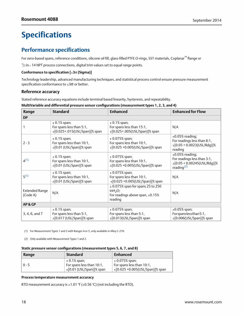
Specifications
Performance specificationsFor zero-based spans, reference conditions, silicone oil fill, glass-filled PTFE O-rings, SST materials, Coplanar™ flange or
1/2 in.- 14 NPT process connections, digital trim values set to equal range points.
Conformance to specification [±3σ (Sigma)]
Technology leadership, advanced manufacturing techniques, and statistical process control ensure pressure measurement specification conformance to ±3σ or better.
Reference accuracy
Stated reference accuracy equations include terminal based linearity, hysteresis, and repeatability.
Process temperature measurement accuracy
RTD measurement accuracy is ±1.01 °F (±0.56 °C) (not including the RTD).
MultiVariable and differential pressure sensor configurations (measurement types 1, 2, 3, and 4)
Range Standard Enhanced Enhanced for Flow
DP
1± 0.1% span;For spans less than 5:1,±[0.025+.015(USL/Span)]% span
± 0.1% span;For spans less than 15:1,±[0.025+.005(USL/Span)]% span
N/A
2 - 3± 0.1% span; For spans less than 10:1,±[0.01 (USL/Span)]% span
± 0.075% span;For spans less than 10:1,±[0.025 +0.005(USL/Span)]% span
±0.05% reading;For readings less than 8:1,±[0.05 + 0.0023(USL/Rdg)]% reading
4(1)± 0.1% span;For spans less than 10:1,±[0.01 (USL/Span)]% span
± 0.075% span;For spans less than 10:1,±[0.025 +0.005(USL/Span)]% span
±0.05% reading;For readings less than 3:1,±[0.05 + 0.00245(USL/Rdg)]% reading(2)
5(1)± 0.1% span;For spans less than 10:1,±[0.01 (USL/Span)]% span
± 0.075% span;For spans less than 10:1, ±[0.025 +0.005(USL/Span)]% span
N/A
Extended Range (Code A)
N/A
± 0.075% span for spans 25 to 250 inH2O;For readings above span, ±0.15% reading
N/A
AP & GP
3, 4, 6, and 7± 0.1% span;For spans less than 5:1,±[0.017 (USL/Span)]% span
± 0.075% span;For spans less than 5:1, ±[0.013(USL/Span)]% span
±0.05% span;For spans less than 5:1, ±[0.006(USL/Span)]% span
(1) For Measurement Types 1 and 2 with Ranges 4 or 5, only available in Alloy C-276.
(2) Only available with Measurement Types 1 and 2.
Static pressure sensor configurations (measurement types 5, 6, 7, and 8)
Range Standard Enhanced
0 - 5± 0.1% span;For spans less than 10:1,±[0.01 (USL/Span)]% span
± 0.075% span;For spans less than 10:1,±[0.025 +0.005(USL/Span)]% span
18 www.rosemount.com
Rosemount 4088September 2014
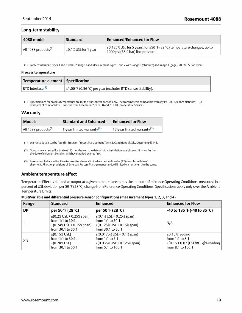
Long-term stability
Process temperature
Warranty
Ambient temperature effect
Temperature Effect is defined as output at a given temperature minus the output at Reference Operating Conditions, measured in ± percent of USL deviation per 50 °F (28 °C) change from Reference Operating Conditions. Specifications apply only over the Ambient Temperature Limits.
4088 model Standard Enhanced/Enhanced for Flow
All 4088 products(1) ±0.1% USL for 1 year±0.125% USL for 5 years; for ±50 °F (28 °C) temperature changes, up to 1000 psi (68,9 bar) line pressure
(1) For Measurement Types 1 and 2 with DP Range 1 and Measurement Types 5 and 7 with Range 0 (absolute) and Range 1 (gage); ±0.2% USL for 1 year.
Temperature element Specification
RTD Interface(1) ±1.00 °F (0.56 °C) per year (excludes RTD sensor stability).
(1) Specifications for process temperature are for the transmitter portion only. The transmitter is compatible with any Pt 100 (100 ohm platinum) RTD. Examples of compatible RTDs include the Rosemount Series 68 and 78 RTD Temperature Sensors.
Models Standard and Enhanced Enhanced for Flow
All 4088 products(1) 1-year limited warranty(2) 12-year limited warranty(3)
(1) Warranty details can be found in Emerson Process Management Terms & Conditions of Sale, Document 63445.
(2) Goods are warranted for twelve (12) months from the date of initial installation or eighteen (18) months from the date of shipment by seller, whichever period expires first.
(3) Rosemount Enhanced for Flow transmitters have a limited warranty of twelve (12) years from date of shipment. All other provisions of Emerson Process Management standard limited warranty remain the same.
MultiVariable and differential pressure sensor configurations (measurement types 1, 2, 3, and 4)
Range Standard Enhanced Enhanced for Flow
DP per 50 °F (28 °C) per 50 °F (28 °C) -40 to 185 °F (-40 to 85 °C)
1
±(0.2% USL + 0.25% span)from 1:1 to 30:1,±(0.24% USL + 0.15% span)from 30:1 to 50:1
±(0.1% USL + 0.25% span)from 1:1 to 30:1,±(0.125% USL + 0.15% span)from 30:1 to 50:1
N/A
2-3
±(0.15% USL)from 1:1 to 30:1,±(0.20% USL)from 30:1 to 50:1
±(0.0175% USL + 0.1% span)from 1:1 to 5:1,±(0.035% USL + 0.125% span) from 5:1 to 100:1
±0.15% readingfrom 1:1 to 8:1,±[0.15 + 0.02 (USL/RDG)]% readingfrom 8:1 to 100:1
19www.rosemount.com
Rosemount 4088 September 2014
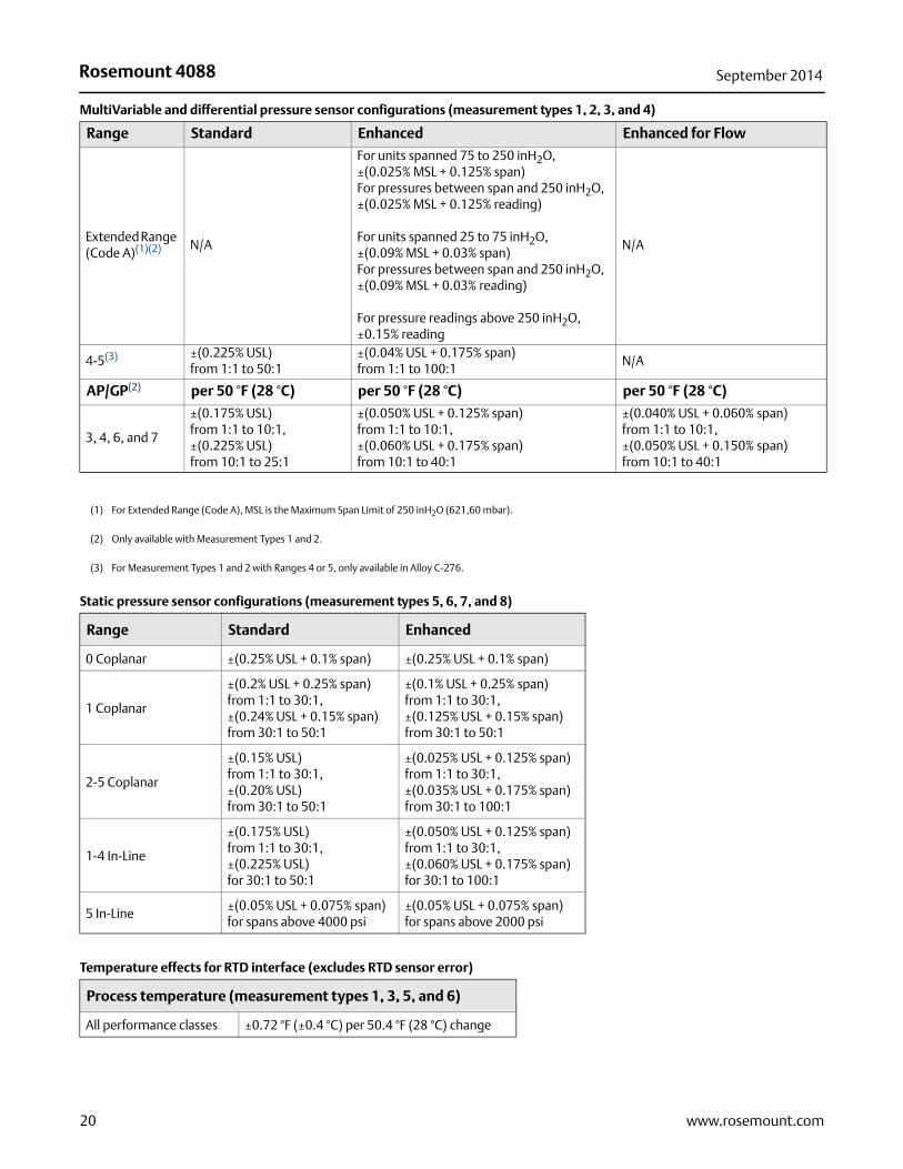
Extended Range (Code A)(1)(2) N/A
For units spanned 75 to 250 inH2O,±(0.025% MSL + 0.125% span)For pressures between span and 250 inH2O, ±(0.025% MSL + 0.125% reading)
For units spanned 25 to 75 inH2O,±(0.09% MSL + 0.03% span) For pressures between span and 250 inH2O, ±(0.09% MSL + 0.03% reading)
For pressure readings above 250 inH2O, ±0.15% reading
N/A
4-5(3) ±(0.225% USL)from 1:1 to 50:1
±(0.04% USL + 0.175% span)from 1:1 to 100:1
N/A
AP/GP(2) per 50 °F (28 °C) per 50 °F (28 °C) per 50 °F (28 °C)
3, 4, 6, and 7
±(0.175% USL)from 1:1 to 10:1,±(0.225% USL)from 10:1 to 25:1
±(0.050% USL + 0.125% span)from 1:1 to 10:1,±(0.060% USL + 0.175% span)from 10:1 to 40:1
±(0.040% USL + 0.060% span)from 1:1 to 10:1,±(0.050% USL + 0.150% span)from 10:1 to 40:1
(1) For Extended Range (Code A), MSL is the Maximum Span Limit of 250 inH2O (621,60 mbar).
(2) Only available with Measurement Types 1 and 2.
(3) For Measurement Types 1 and 2 with Ranges 4 or 5, only available in Alloy C-276.
Static pressure sensor configurations (measurement types 5, 6, 7, and 8)
Range Standard Enhanced
0 Coplanar ±(0.25% USL + 0.1% span) ±(0.25% USL + 0.1% span)
1 Coplanar
±(0.2% USL + 0.25% span)from 1:1 to 30:1,±(0.24% USL + 0.15% span)from 30:1 to 50:1
±(0.1% USL + 0.25% span)from 1:1 to 30:1,±(0.125% USL + 0.15% span)from 30:1 to 50:1
2-5 Coplanar
±(0.15% USL)from 1:1 to 30:1,±(0.20% USL)from 30:1 to 50:1
±(0.025% USL + 0.125% span)from 1:1 to 30:1,±(0.035% USL + 0.175% span)from 30:1 to 100:1
1-4 In-Line
±(0.175% USL)from 1:1 to 30:1,±(0.225% USL)for 30:1 to 50:1
±(0.050% USL + 0.125% span)from 1:1 to 30:1, ±(0.060% USL + 0.175% span)for 30:1 to 100:1
5 In-Line±(0.05% USL + 0.075% span)for spans above 4000 psi
±(0.05% USL + 0.075% span)for spans above 2000 psi
MultiVariable and differential pressure sensor configurations (measurement types 1, 2, 3, and 4)
Range Standard Enhanced Enhanced for Flow
Temperature effects for RTD interface (excludes RTD sensor error)
Process temperature (measurement types 1, 3, 5, and 6)
All performance classes ±0.72 °F (±0.4 °C) per 50.4 °F (28 °C) change
20 www.rosemount.com
Rosemount 4088September 2014
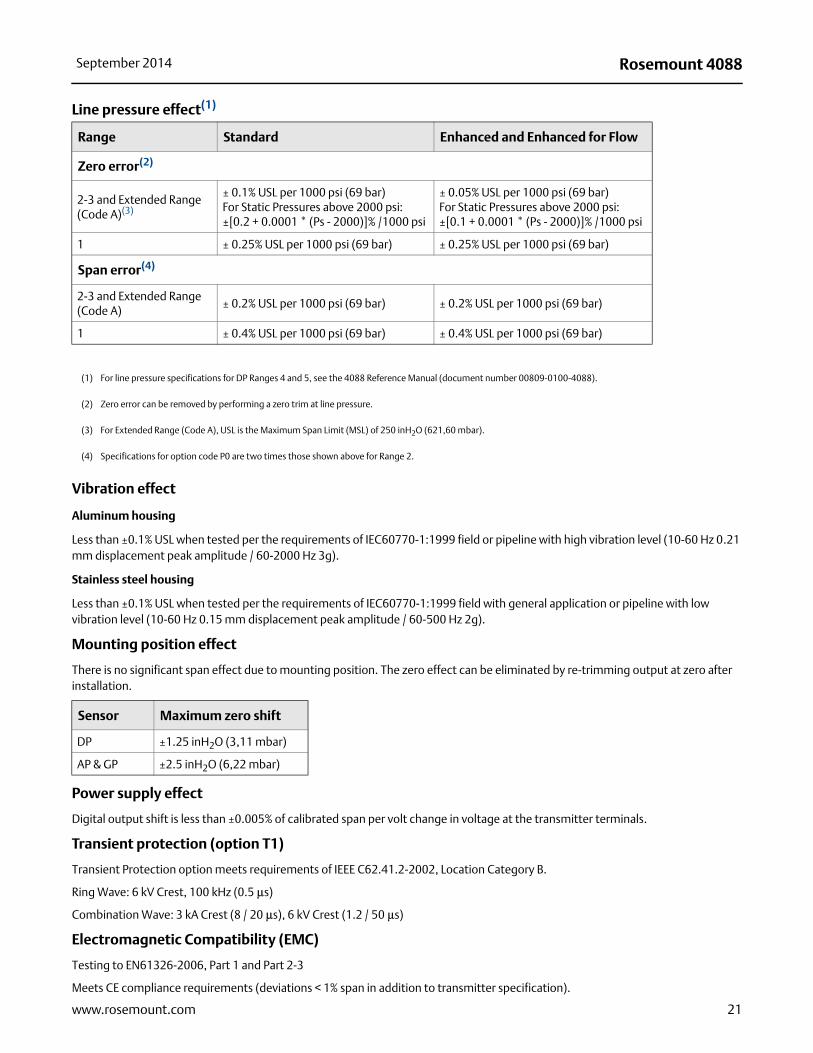
Vibration effect
Aluminum housing
Less than ±0.1% USL when tested per the requirements of IEC60770-1:1999 field or pipeline with high vibration level (10-60 Hz 0.21 mm displacement peak amplitude / 60-2000 Hz 3g).
Stainless steel housing
Less than ±0.1% USL when tested per the requirements of IEC60770-1:1999 field with general application or pipeline with low vibration level (10-60 Hz 0.15 mm displacement peak amplitude / 60-500 Hz 2g).
Mounting position effect
There is no significant span effect due to mounting position. The zero effect can be eliminated by re-trimming output at zero after installation.
Power supply effect
Digital output shift is less than ±0.005% of calibrated span per volt change in voltage at the transmitter terminals.
Transient protection (option T1)
Transient Protection option meets requirements of IEEE C62.41.2-2002, Location Category B.
Ring Wave: 6 kV Crest, 100 kHz (0.5 μs)
Combination Wave: 3 kA Crest (8 / 20 μs), 6 kV Crest (1.2 / 50 μs)
Electromagnetic Compatibility (EMC)
Testing to EN61326-2006, Part 1 and Part 2-3
Meets CE compliance requirements (deviations < 1% span in addition to transmitter specification).
Line pressure effect(1)
Range Standard Enhanced and Enhanced for Flow
Zero error(2)
2-3 and Extended Range (Code A)(3)
± 0.1% USL per 1000 psi (69 bar) For Static Pressures above 2000 psi:±[0.2 + 0.0001 * (Ps - 2000)]% /1000 psi
± 0.05% USL per 1000 psi (69 bar) For Static Pressures above 2000 psi:±[0.1 + 0.0001 * (Ps - 2000)]% /1000 psi
1 ± 0.25% USL per 1000 psi (69 bar) ± 0.25% USL per 1000 psi (69 bar)
Span error(4)
2-3 and Extended Range (Code A)
± 0.2% USL per 1000 psi (69 bar) ± 0.2% USL per 1000 psi (69 bar)
1 ± 0.4% USL per 1000 psi (69 bar) ± 0.4% USL per 1000 psi (69 bar)
(1) For line pressure specifications for DP Ranges 4 and 5, see the 4088 Reference Manual (document number 00809-0100-4088).
(2) Zero error can be removed by performing a zero trim at line pressure.
(3) For Extended Range (Code A), USL is the Maximum Span Limit (MSL) of 250 inH2O (621,60 mbar).
(4) Specifications for option code P0 are two times those shown above for Range 2.
Sensor Maximum zero shift
DP ±1.25 inH2O (3,11 mbar)
AP & GP ±2.5 inH2O (6,22 mbar)
21www.rosemount.com
Rosemount 4088 September 2014
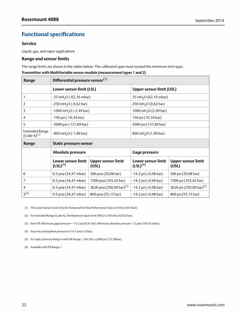
Functional specifications
Service
Liquid, gas, and vapor applications
Range and sensor limits
The range limits are shown in the tables below. The calibrated span must exceed the minimum trim span.
Transmitter with MultiVariable sensor module (measurement types 1 and 2)
Range Differential pressure sensor(1)
Lower sensor limit (LSL) Upper sensor limit (USL)
1 -25 inH2O (-62,16 mbar) 25 inH2O (62,16 mbar)
2 -250 inH2O (-0,62 bar) 250 inH2O (0,62 bar)
3 -1000 inH2O (-2,49 bar) 1000 inH2O (2,49 bar)
4 -150 psi (-10,34 bar) 150 psi (10,34 bar)
5 -2000 psi (-137,89 bar) 2000 psi (137,89 bar)
Extended Range (Code A)(2) -800 inH2O (-1,99 bar) 800 inH2O (1,99 bar)
Range Static pressure sensor
Absolute pressure Gage pressure
Lower sensor limit (LSL)(3)
Upper sensor limit (USL)
Lower sensor limit (LSL)(4)
Upper sensor limit (USL)
6 0.5 psia (34,47 mbar) 300 psia (20,68 bar) -14.2 psi (-0,98 bar) 300 psi (20,68 bar)
7 0.5 psia (34,47 mbar) 1500 psia (103,42 bar) -14.2 psi (-0,98 bar) 1500 psi (103,42 bar)
4 0.5 psia (34,47 mbar) 3626 psia (250,00 bar)(5) -14.2 psi (-0,98 bar) 3626 psi (250,00 bar)(5)
3(6) 0.5 psia (34,47 mbar) 800 psia (55,15 bar) -14.2 psi (-0,98 bar) 800 psi (55,15 bar)
(1) The Lower Sensor Limit (LSL) for Enhanced for Flow Performance Class is 0 inH2O (0 mbar).
(2) For Extended Range (Code A), the Maximum Span Limit (MSL) is 250 inH2O (0,62 bar).
(3) Inert Fill: Minimum gage pressure = -13.2 psi (0,91 bar); Minimum absolute pressure: 1.5 psia (103,42 mbar).
(4) Assumes atmosphere pressure of 14.7 psia (1,0 bar).
(5) For static pressure Range 4 with DP Range 1, the USL is 2000 psi (137,89bar).
(6) Available with DP Range 1.
22 www.rosemount.com
Rosemount 4088September 2014
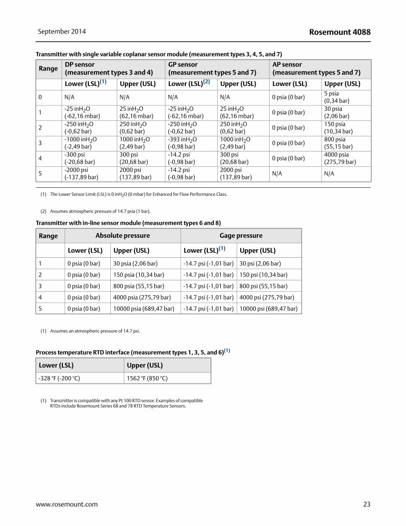
Transmitter with single variable coplanar sensor module (measurement types 3, 4, 5, and 7)
RangeDP sensor (measurement types 3 and 4)
GP sensor (measurement types 5 and 7)
AP sensor (measurement types 5 and 7)
Lower (LSL)(1) Upper (USL) Lower (LSL)(2) Upper (USL) Lower (LSL) Upper (USL)
0 N/A N/A N/A N/A 0 psia (0 bar)5 psia(0,34 bar)
1-25 inH2O(-62,16 mbar)
25 inH2O(62,16 mbar)
-25 inH2O(-62,16 mbar)
25 inH2O(62,16 mbar)
0 psia (0 bar)30 psia(2,06 bar)
2-250 inH2O(-0,62 bar)
250 inH2O(0,62 bar)
-250 inH2O(-0,62 bar)
250 inH2O(0,62 bar)
0 psia (0 bar)150 psia(10,34 bar)
3-1000 inH2O(-2,49 bar)
1000 inH2O(2,49 bar)
-393 inH2O(-0,98 bar)
1000 inH2O(2,49 bar)
0 psia (0 bar)800 psia(55,15 bar)
4-300 psi(-20,68 bar)
300 psi(20,68 bar)
-14.2 psi(-0,98 bar)
300 psi(20,68 bar)
0 psia (0 bar)4000 psia(275,79 bar)
5-2000 psi(-137,89 bar)
2000 psi(137,89 bar)
-14.2 psi(-0,98 bar)
2000 psi(137,89 bar)
N/A N/A
(1) The Lower Sensor Limit (LSL) is 0 inH2O (0 mbar) for Enhanced for Flow Performance Class.
(2) Assumes atmospheric pressure of 14.7 psia (1 bar).
Transmitter with in-line sensor module (measurement types 6 and 8)
Range Absolute pressure Gage pressure
Lower (LSL) Upper (USL) Lower (LSL)(1) Upper (USL)
1 0 psia (0 bar) 30 psia (2,06 bar) -14.7 psi (-1,01 bar) 30 psi (2,06 bar)
2 0 psia (0 bar) 150 psia (10,34 bar) -14.7 psi (-1,01 bar) 150 psi (10,34 bar)
3 0 psia (0 bar) 800 psia (55,15 bar) -14.7 psi (-1,01 bar) 800 psi (55,15 bar)
4 0 psia (0 bar) 4000 psia (275,79 bar) -14.7 psi (-1,01 bar) 4000 psi (275,79 bar)
5 0 psia (0 bar) 10000 psia (689,47 bar) -14.7 psi (-1,01 bar) 10000 psi (689,47 bar)
(1) Assumes an atmospheric pressure of 14.7 psi.
Process temperature RTD interface (measurement types 1, 3, 5, and 6)(1)
Lower (LSL) Upper (USL)
-328 °F (-200 °C) 1562 °F (850 °C)
(1) Transmitter is compatible with any Pt 100 RTD sensor. Examples of compatible RTDs include Rosemount Series 68 and 78 RTD Temperature Sensors.
23www.rosemount.com

Rosemount 4088 September 2014
Minimum span limits
Transmitter with MultiVariable sensor module (measurement types 1 and 2)
Differential pressure range Standard Enhanced Enhanced for Flow
1 1.0 inH2O (2,49 mbar) 0.50 inH2O (1,24 mbar) N/A
2 5.0 inH2O (12,43 mbar) 2.5 inH2O (6,22 mbar) 2.5 inH2O (6,22 mbar)
3 20.0 inH2O (49,73 mbar) 10.0 inH2O (24,86 mbar) 10.0 inH2O (24,86 mbar)
4 6.0 psi (0,41 bar) 3.0 psi (0,21 bar) 3.0 psi (0,21 bar)
5 40.0 psi (2,76 bar) 20.0 psi (1,38 bar) N/A
Extended Range (Code A)(1)
(1) For Extended Range (Code A), the Maximum Span Limit (MSL) is 250 inH2O (0,62 bar)
N/A 25 inH2O (62,16 mbar) N/A
Static pressure range Standard Enhanced Enhanced for Flow
Allowable static pressure ranges for DP Range 2-5, A
4 145.00 psi (10,00 bar) 90.00 psi (6,21 bar) 90.00 psi (6,21 bar)
6 12.00 psi (0,83 bar) 7.50 psi (5,17 bar) 7.50 psi (5,17 bar)
7 60.00 psi (4,14 bar) 37.50 psi (2,59 bar) 37.50 psi (2,59 bar)
Allowable static pressure ranges for DP Range 1
3 32.00 psi (2,21 bar) 20.00 psi (1,38 bar) N/A
4 145.00 psi (10,00 bar) 90.00 psi (6,21 bar) N/A
Transmitter with single variable coplanar sensor module (measurement types 3, 4, 5, and 7)
DP/GP range Standard Enhanced Enhanced for Flow(1)
1 1.0 inH2O (2,49 mbar) 0.5 inH2O (1,24 mbar) N/A
2 5.0 inH2O (12,43 mbar) 2.5 inH2O (6,22 mbar) 2.5 inH2O (6,22 mbar)
3 20.0 inH2O (49,73 mbar) 10.0 inH2O (24,86 mbar) 5.0 inH2O (12,43 mbar)
4 6.0 psi (0,41 bar) 3.0 psi (0,21 bar) N/A
5 40.0 psi (2,76 bar) 20.0 psi (1,38 bar) N/A
(1) Only available for differential pressure sensors (Measurement Types 3 and 4).
Transmitter with coplanar absolute pressure sensor module (measurement types 5 and 7)
AP range Standard Enhanced
0 0.3 psia (20,68 mbar) 0.3 psia (20,68 mbar)
1 0.6 psia (41,37 mbar) 0.3 psia (20,68 mbar)
2 3.0 psia (0,21 bar) 1.5 psia (0,10 bar)
3 16.0 psia (1,10 bar) 8.0 psia (0,55 bar)
4 80 psia (5,52 bar) 40 psia (2,76 bar)
24 www.rosemount.com
Rosemount 4088September 2014
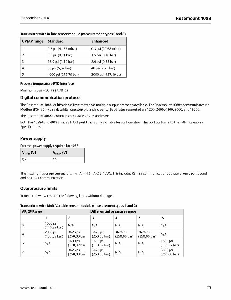
Process temperature RTD interface
Minimum span = 50 °F (27.78 °C)
Digital communication protocol
The Rosemount 4088 MultiVariable Transmitter has multiple output protocols available. The Rosemount 4088A communicates via Modbus (RS-485) with 8 data bits, one stop bit, and no parity. Baud rates supported are 1200, 2400, 4800, 9600, and 19200.
The Rosemount 4088B communicates via MVS 205 and BSAP.
Both the 4088A and 4088B have a HART port that is only available for configuration. This port conforms to the HART Revision 7 Specifications.
Power supply
External power supply required for 4088
The maximum average current is Imax (mA) = 4.6mA @ 5.4VDC. This includes RS-485 communication at a rate of once per second and no HART communication.
Overpressure limits
Transmitter will withstand the following limits without damage.
Transmitter with in-line sensor module (measurement types 6 and 8)
GP/AP range Standard Enhanced
1 0.6 psi (41,37 mbar) 0.3 psi (20,68 mbar)
2 3.0 psi (0,21 bar) 1.5 psi (0,10 bar)
3 16.0 psi (1,10 bar) 8.0 psi (0,55 bar)
4 80 psi (5,52 bar) 40 psi (2,76 bar)
5 4000 psi (275,79 bar) 2000 psi (137,89 bar)
Vmin (V) Vmax (V)
5.4 30
Transmitter with MultiVariable sensor module (measurement types 1 and 2)
AP/GP Range Differential pressure range
1 2 3 4 5 A
31600 psi(110,32 bar)
N/A N/A N/A N/A N/A
42000 psi(137,89 bar)
3626 psi(250,00 bar)
3626 psi(250,00 bar)
3626 psi(250,00 bar)
3626 psi(250,00 bar)
N/A
6 N/A1600 psi(110,32 bar)
1600 psi(110,32 bar)
N/A N/A1600 psi(110,32 bar)
7 N/A3626 psi(250,00 bar)
3626 psi(250,00 bar)
N/A N/A3626 psi(250,00 bar)
25www.rosemount.com
Rosemount 4088 September 2014
SD
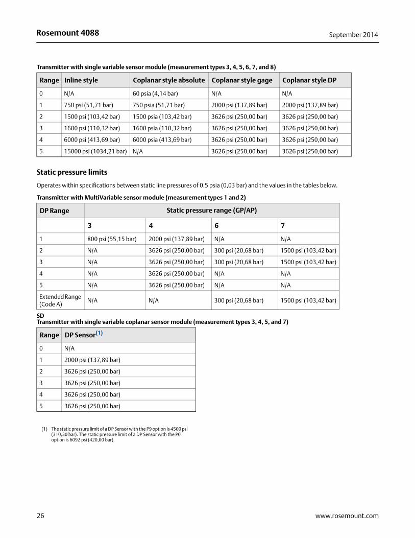
Transmitter with single variable sensor module (measurement types 3, 4, 5, 6, 7, and 8)
Range Inline style Coplanar style absolute Coplanar style gage Coplanar style DP
0 N/A 60 psia (4,14 bar) N/A N/A
1 750 psi (51,71 bar) 750 psia (51,71 bar) 2000 psi (137,89 bar) 2000 psi (137,89 bar)
2 1500 psi (103,42 bar) 1500 psia (103,42 bar) 3626 psi (250,00 bar) 3626 psi (250,00 bar)
3 1600 psi (110,32 bar) 1600 psia (110,32 bar) 3626 psi (250,00 bar) 3626 psi (250,00 bar)
4 6000 psi (413,69 bar) 6000 psia (413,69 bar) 3626 psi (250,00 bar) 3626 psi (250,00 bar)
5 15000 psi (1034,21 bar) N/A 3626 psi (250,00 bar) 3626 psi (250,00 bar)
Static pressure limits
Operates within specifications between static line pressures of 0.5 psia (0,03 bar) and the values in the tables below.
Transmitter with MultiVariable sensor module (measurement types 1 and 2)
DP Range Static pressure range (GP/AP)
3 4 6 7
1 800 psi (55,15 bar) 2000 psi (137,89 bar) N/A N/A
2 N/A 3626 psi (250,00 bar) 300 psi (20,68 bar) 1500 psi (103,42 bar)
3 N/A 3626 psi (250,00 bar) 300 psi (20,68 bar) 1500 psi (103,42 bar)
4 N/A 3626 psi (250,00 bar) N/A N/A
5 N/A 3626 psi (250,00 bar) N/A N/A
Extended Range (Code A)
N/A N/A 300 psi (20,68 bar) 1500 psi (103,42 bar)
Transmitter with single variable coplanar sensor module (measurement types 3, 4, 5, and 7)
Range DP Sensor(1)
(1) The static pressure limit of a DP Sensor with the P9 option is 4500 psi (310,30 bar). The static pressure limit of a DP Sensor with the P0 option is 6092 psi (420,00 bar).
0 N/A
1 2000 psi (137,89 bar)
2 3626 psi (250,00 bar)
3 3626 psi (250,00 bar)
4 3626 psi (250,00 bar)
5 3626 psi (250,00 bar)
26 www.rosemount.com
Rosemount 4088September 2014
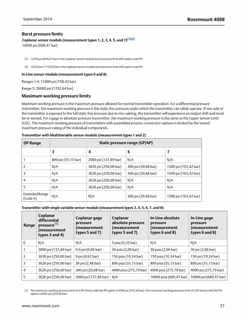
Burst pressure limits
In-Line sensor module (measurement types 6 and 8)
Ranges 1-4: 11000 psi (758,42 bar)
Range 5: 26000 psi (1792,64 bar)
Maximum working pressure limits
Maximum working pressure is the maximum pressure allowed for normal transmitter operation. For a differential pressure transmitter, the maximum working pressure is the static line pressure under which the transmitter can safely operate. If one side of the transmitter is exposed to the full static line pressure due to mis-valving, the transmitter will experience an output shift and must be re-zeroed. For a gage or absolute pressure transmitter, the maximum working pressure is the same as the Upper Sensor Limit (USL). The maximum working pressure of transmitters with assembled process connection options is limited by the lowest maximum pressure rating of the individual components.
Coplanar sensor module (measurement types 1, 2, 3, 4, 5, and 7)(1)(2)
10000 psi (689,47 bar)
(1) 12250 psi (844,61 bar) is the Coplanar sensor module burst pressure limit with option code P9.
(2) 16230 psi (1119,02 bar) is the Coplanar sensor module burst pressure limit with option code P0.
Transmitter with MultiVariable sensor module (measurement types 1 and 2)
DP Range Static pressure range (GP/AP)
3 4 6 7
1 800 psi (55,15 bar) 2000 psi (137,89 bar) N/A N/A
2 N/A 3626 psi (250,00 bar) 300 psi (20,68 bar) 1500 psi (103,42 bar)
3 N/A 3626 psi (250,00 bar) 300 psi (20,68 bar) 1500 psi (103,42 bar)
4 N/A 3626 psi (250,00 bar) N/A N/A
5 N/A 3626 psi (250,00 bar) N/A N/A
Extended Range (Code A)
N/A N/A 300 psi (20,68 bar) 1500 psi (103,42 bar)
Transmitter with single variable sensor module (measurement types 3, 4, 5, 6, 7, and 8)
Range
Coplanardifferentialpressure(1)
(measurementtypes 3 and 4)
Coplanar gagepressure(measurementtypes 5 and 7)
Coplanarabsolute pressure(measurementtypes 5 and 7)
In-Line absolutepressure(measurementtypes 6 and 8)
In-Line gagepressure(measurementtypes 6 and 8)
0 N/A N/A 5 psia (0,35 bar) N/A N/A
1 2000 psi (137,89 bar) 0.9 psi (0,06 bar) 30 psia (2,06 bar) 30 psia (2,06 bar) 30 psi (2,06 bar)
2 3626 psi (250,00 bar) 9 psi (0,62 bar) 150 psia (10,34 bar) 150 psia (10,34 bar) 150 psi (10,34 bar)
3 3626 psi (250,00 bar) 36 psi (2,48 bar) 800 psia (55,15 bar) 800 psia (55,15 bar) 800 psi (55,15 bar)
4 3626 psi (250,00 bar) 300 psi (20,68 bar) 4000 psia (275,79 bar) 4000 psia (275,79 bar) 4000 psi (275,79 bar)
5 3626 psi (250,00 bar) 2000 psi (137,89 bar) N/A 10000 psia (689,47 bar) 10000 psi (689,47 bar)
(1) The maximum working pressure limit of a DP Sensor with the P9 option is 4500 psi (310,30 bar). The maximum working pressure limit of a DP Sensor with the P0 option is 6092 psi (420,00 bar).
27www.rosemount.com
Rosemount 4088 September 2014
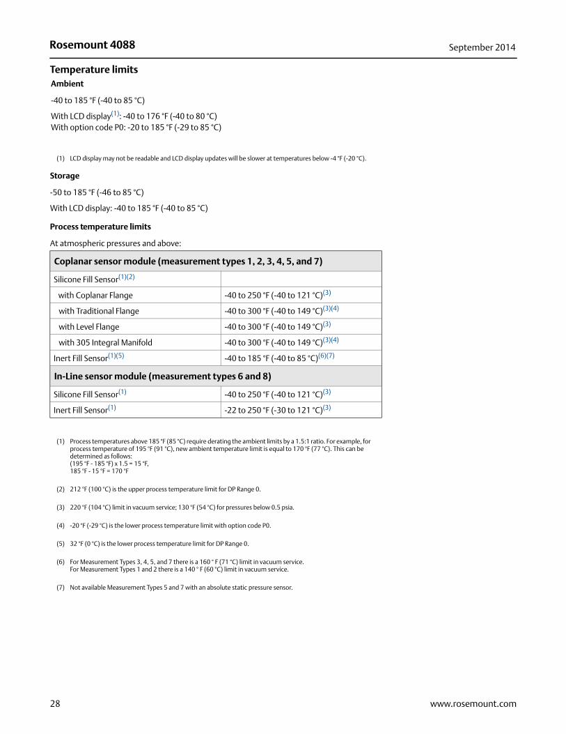
Temperature limits
Storage
-50 to 185 °F (-46 to 85 °C)
With LCD display: -40 to 185 °F (-40 to 85 °C)
Ambient
-40 to 185 °F (-40 to 85 °C)
With LCD display(1): -40 to 176 °F (-40 to 80 °C)With option code P0: -20 to 185 °F (-29 to 85 °C)
(1) LCD display may not be readable and LCD display updates will be slower at temperatures below -4 °F (-20 °C).
Process temperature limits
At atmospheric pressures and above:
Coplanar sensor module (measurement types 1, 2, 3, 4, 5, and 7)
Silicone Fill Sensor(1)(2)
(1) Process temperatures above 185 °F (85 °C) require derating the ambient limits by a 1.5:1 ratio. For example, for process temperature of 195 °F (91 °C), new ambient temperature limit is equal to 170 °F (77 °C). This can be determined as follows: (195 °F - 185 °F) x 1.5 = 15 °F,185 °F - 15 °F = 170 °F
(2) 212 °F (100 °C) is the upper process temperature limit for DP Range 0.
with Coplanar Flange -40 to 250 °F (-40 to 121 °C)(3)
(3) 220 °F (104 °C) limit in vacuum service; 130 °F (54 °C) for pressures below 0.5 psia.
with Traditional Flange -40 to 300 °F (-40 to 149 °C)(3)(4)
(4) -20 °F (-29 °C) is the lower process temperature limit with option code P0.
with Level Flange -40 to 300 °F (-40 to 149 °C)(3)
with 305 Integral Manifold -40 to 300 °F (-40 to 149 °C)(3)(4)
Inert Fill Sensor(1)(5)
(5) 32 °F (0 °C) is the lower process temperature limit for DP Range 0.
-40 to 185 °F (-40 to 85 °C)(6)(7)
(6) For Measurement Types 3, 4, 5, and 7 there is a 160 ° F (71 °C) limit in vacuum service. For Measurement Types 1 and 2 there is a 140 ° F (60 °C) limit in vacuum service.
(7) Not available Measurement Types 5 and 7 with an absolute static pressure sensor.
In-Line sensor module (measurement types 6 and 8)
Silicone Fill Sensor(1) -40 to 250 °F (-40 to 121 °C)(3)
Inert Fill Sensor(1) -22 to 250 °F (-30 to 121 °C)(3)
28 www.rosemount.com
Rosemount 4088September 2014
Humidity limits
0 to 100% relative humidity
Turn-on time
Transmitter performance will be within specifications within 5 seconds of power being applied.
Volumetric displacement
Less than 0.005 in3 (0,08 cm3)
Damping
Output response time to a step change is user-selectable from 0 to 60 seconds for one time constant. Each measured variable (Differential Pressure, Static Pressure, and Process Temperature) can be individually adjusted. Software damping is in addition to sensor module response time.
29www.rosemount.com
Rosemount 4088 September 2014
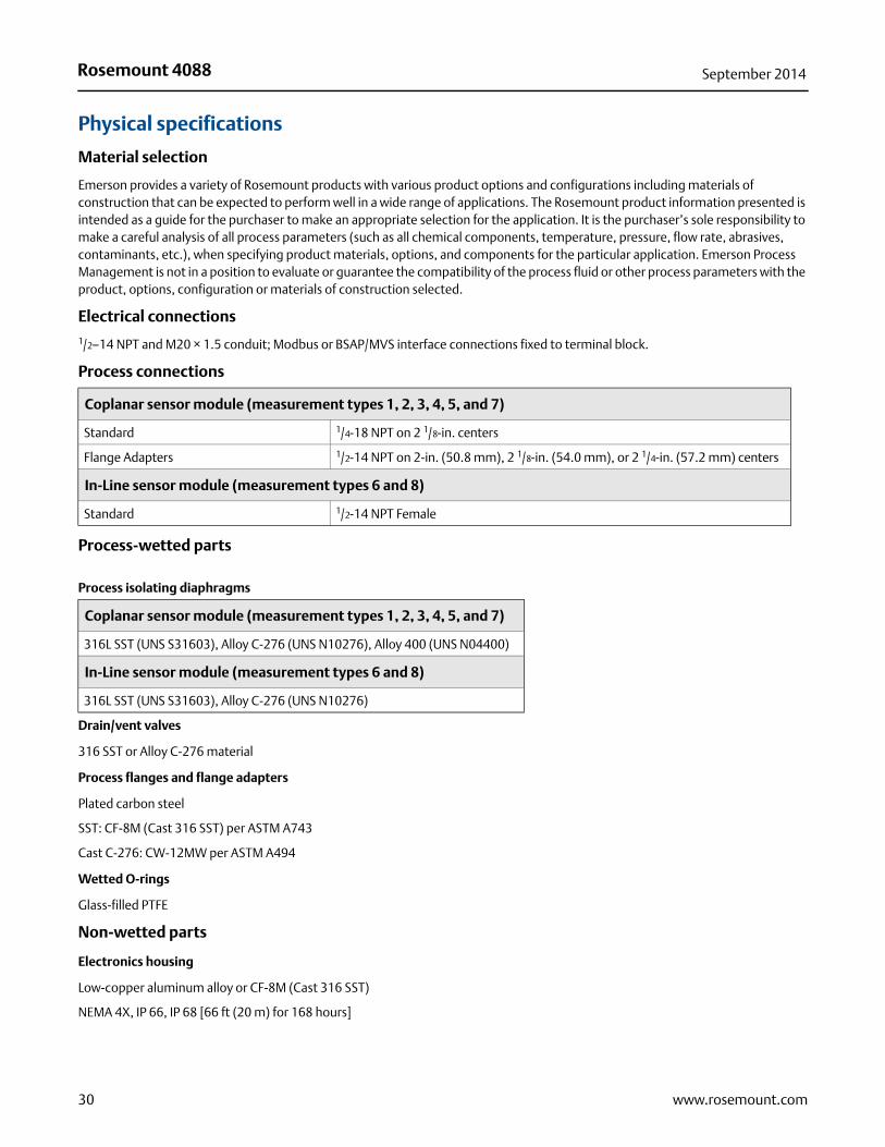
Physical specifications
Material selection
Emerson provides a variety of Rosemount products with various product options and configurations including materials of construction that can be expected to perform well in a wide range of applications. The Rosemount product information presented is intended as a guide for the purchaser to make an appropriate selection for the application. It is the purchaser’s sole responsibility to make a careful analysis of all process parameters (such as all chemical components, temperature, pressure, flow rate, abrasives, contaminants, etc.), when specifying product materials, options, and components for the particular application. Emerson Process Management is not in a position to evaluate or guarantee the compatibility of the process fluid or other process parameters with the product, options, configuration or materials of construction selected.
Electrical connections1/2–14 NPT and M20 × 1.5 conduit; Modbus or BSAP/MVS interface connections fixed to terminal block.
Process connections
Process-wetted parts
Drain/vent valves
316 SST or Alloy C-276 material
Process flanges and flange adapters
Plated carbon steel
SST: CF-8M (Cast 316 SST) per ASTM A743
Cast C-276: CW-12MW per ASTM A494
Wetted O-rings
Glass-filled PTFE
Non-wetted parts
Electronics housing
Low-copper aluminum alloy or CF-8M (Cast 316 SST)
NEMA 4X, IP 66, IP 68 [66 ft (20 m) for 168 hours]
Coplanar sensor module (measurement types 1, 2, 3, 4, 5, and 7)
Standard 1/4-18 NPT on 2 1/8-in. centers
Flange Adapters 1/2-14 NPT on 2-in. (50.8 mm), 2 1/8-in. (54.0 mm), or 2 1/4-in. (57.2 mm) centers
In-Line sensor module (measurement types 6 and 8)
Standard 1/2-14 NPT Female
Process isolating diaphragms
Coplanar sensor module (measurement types 1, 2, 3, 4, 5, and 7)
316L SST (UNS S31603), Alloy C-276 (UNS N10276), Alloy 400 (UNS N04400)
In-Line sensor module (measurement types 6 and 8)
316L SST (UNS S31603), Alloy C-276 (UNS N10276)
30 www.rosemount.com

Rosemount 4088September 2014
Sensor module housing
SST: CF-3M (Cast 316L SST)
Bolts
Plated carbon steel per ASTM A449, Type 1
Austenitic 316 SST per ASTM F593
ASTM A453, Class D, Grade 660 SST
ASTM A193, Grade B7M alloy steel
ASTM A193, Class 2, Grade B8M SST
Alloy K-500
Sensor module fill fluid
Silicone or inert halocarbon (inert not available with coplanar absolute pressure sensors). Inert for in-line series uses Fluorinert®
FC-43.
Paint for aluminum housing
Polyurethane
Cover O-rings
Buna-N
Shipping weights
Sensor module weights(1)
(1) Flange and bolts not included.
Coplanar sensor module
3.1 lb (1,4 kg)
In-Line sensor module
1.4 lb (0,6 kg)
Transmitter weights(1)
(1) Fully functional transmitter with sensor module, housing, terminal block, and covers. Does not include LCD display.
Transmitter with coplanar sensor module (measurement types 1, 2, 3, 4, 5, and 7)
Aluminum housing, SST Flange 5.39 lb (2,44 kg)
Transmitter with in-line sensor module (measurement types 6 and 8)
Aluminum housing 3.65 lb (1,66 kg)
31www.rosemount.com
Rosemount 4088 September 2014
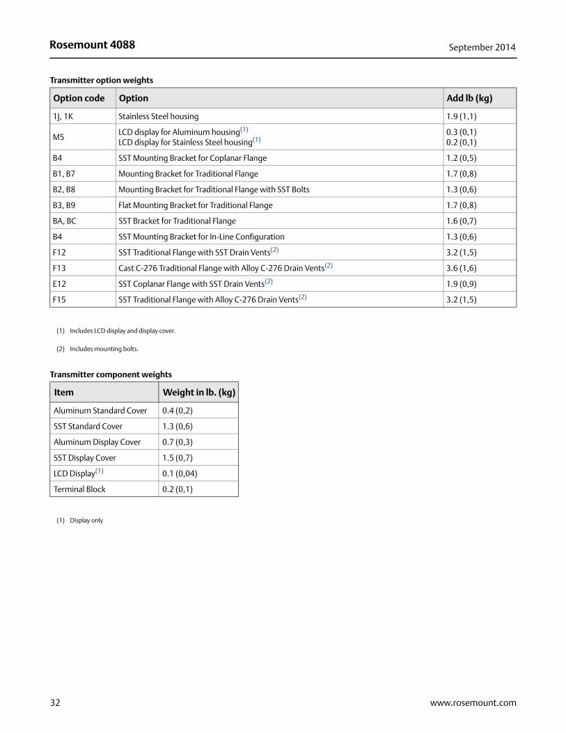
Transmitter option weights
Option code Option Add lb (kg)
1J, 1K Stainless Steel housing 1.9 (1,1)
M5LCD display for Aluminum housing(1)
LCD display for Stainless Steel housing(1)0.3 (0,1)0.2 (0,1)
B4 SST Mounting Bracket for Coplanar Flange 1.2 (0,5)
B1, B7 Mounting Bracket for Traditional Flange 1.7 (0,8)
B2, B8 Mounting Bracket for Traditional Flange with SST Bolts 1.3 (0,6)
B3, B9 Flat Mounting Bracket for Traditional Flange 1.7 (0,8)
BA, BC SST Bracket for Traditional Flange 1.6 (0,7)
B4 SST Mounting Bracket for In-Line Configuration 1.3 (0,6)
F12 SST Traditional Flange with SST Drain Vents(2) 3.2 (1,5)
F13 Cast C-276 Traditional Flange with Alloy C-276 Drain Vents(2) 3.6 (1,6)
E12 SST Coplanar Flange with SST Drain Vents(2) 1.9 (0,9)
F15 SST Traditional Flange with Alloy C-276 Drain Vents(2) 3.2 (1,5)
(1) Includes LCD display and display cover.
(2) Includes mounting bolts.
Transmitter component weights
Item Weight in lb. (kg)
Aluminum Standard Cover 0.4 (0,2)
SST Standard Cover 1.3 (0,6)
Aluminum Display Cover 0.7 (0,3)
SST Display Cover 1.5 (0,7)
LCD Display(1)
(1) Display only
0.1 (0,04)
Terminal Block 0.2 (0,1)
32 www.rosemount.com
Rosemount 4088September 2014
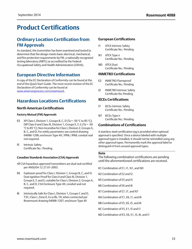
Product Certifications
Ordinary Location Certification from FM ApprovalsAs standard, the transmitter has been examined and tested to determine that the design meets basic electrical, mechanical, and fire protection requirements by FM, a nationally recognized testing laboratory (NRTL) as accredited by the Federal Occupational Safety and Health Administration (OSHA).
European Directive InformationA copy of the EC Declaration of Conformity can be found at the end of the Quick Start Guide. The most recent revision of the EC Declaration of Conformity can be found at www.emersonprocess.com/rosemount.
Hazardous Locations Certifications
North American Certifications
Factory Mutual (FM) Approvals
E5 XP Class I, Division 1, Groups B, C, D (Ta = -50 °C to 85 °C); DIP Class II and Class III, Division 1, Groups E, F, G (Ta = -50 °C to 85 °C); Non-Incendive for Class I, Division 2, Groups A, B, C, and D; For entity parameters see control drawing 04088-1206; enclosure Type 4X / IP66 / IP68; conduit seal not required.
I5 Intrinsic Safety Certificate No.: Pending
Canadian Standards Association (CSA) Approvals
All CSA hazardous approved transmitters are dual seal certified per ANSI/ISA 12.27.01-2003.
E6 Explosion-proof for Class I, Division 1, Groups B, C, and D; Dust-Ignition-Proof for Class II and Class III, Division 1, Groups E, F, and G; suitable for Class I, Division 2, Groups A, B, C, and D, CSA Enclosure Type 4X; conduit seal not required.
I6 Intrinsically Safe for Class I, Division 1, Groups C and D, T3C; Class I, Zone 0, Ex ia IIb, T4; when connected per Rosemount drawing 04088-1207; enclosure Type 4X
European Certifications
I1 ATEX Intrinsic Safety Certificate No.: Pending
N1 ATEX Type n Certificate No.: Pending
ND ATEX DustCertificate No.: Pending
INMETRO Certifications
E2 INMETRO FlameproofCertificate No.: Pending
I2 INMETRO Intrinsic SafetyCertificate No: Pending
IECEx Certifications
I7 IECEx Intrinsic SafetyCertificate No.: Pending
N7 IECEx Type nCertificate No.: Pending
Combinations of Certifications
A stainless steel certification tag is provided when optional approval is specified. Once a device labeled with multiple approval types is installed, it should not be reinstalled using any other approval types. Permanently mark the approval label to distinguish it from unused approval types.
NoteThe following combination certifications are pending until the aforementioned certifications are received.
K1 Combination of E1, I1, N1, and ND
K2 Combination of E2 and I2
K5 Combination of E5 and I5
K6 Combination of E6 and I6
K7 Combination of E7, I7, and N7
KA Combination of E1, E6, I1, and I6
KB Combination of E5, E6, I5, and I6
KC Combination of E5, E1, I5 and I1
KD Combination of E5, E6, E1, I5, I6, and I1
33www.rosemount.com

Rosemount 4088 September 2014
Dimensional Drawings
Process adapters (option D2) and Rosemount 305 integral manifolds must be ordered with the transmitter.
Transmitter with Coplanar Sensor Module and Coplanar Flange
Dimensions are in inches (millimeters).
Transmitter with Coplanar Sensor Module and Traditional Flange
Dimensions are in inches (millimeters).
4.20 (107)
8.53(217)
9.63(245)
4.51 (115)
6.55 (166)
1.63(41)
2.13 (54)
9.26(235)
3.40 (86)1.10(28)
34 www.rosemount.com
Rosemount 4088September 2014
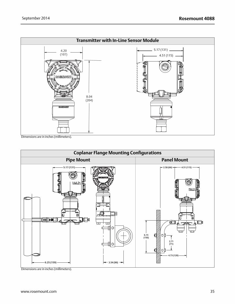
Transmitter with In-Line Sensor Module
Dimensions are in inches (millimeters).
Coplanar Flange Mounting Configurations
Pipe Mount Panel Mount
Dimensions are in inches (millimeters).
4.20 (107)
8.04(204)
5.21 (132)
4.55 (116)
5.17 (131)
4.51 (115)
6.25 (159)
5.17 (131)
3.54 (90)
4.73 (120)
4.51 (115)2.58 (66)
6.15(156)
2.71(71)
35www.rosemount.com
Rosemount 4088 September 2014
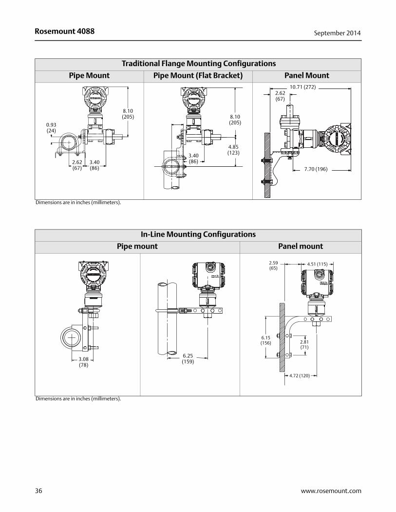
Traditional Flange Mounting Configurations
Pipe Mount Pipe Mount (Flat Bracket) Panel Mount
Dimensions are in inches (millimeters).
In-Line Mounting Configurations
Pipe mount Panel mount
Dimensions are in inches (millimeters).
8.10(205)
0.93 (24)
2.62 (67)
3.40 (86)
4.85 (123)3.40
(86)
8.10 (205)
10.71 (272)2.62(67)
7.70 (196)
3.08 (78)
6.25 (159)
6.15 2.81(71)
4.72 (120)
4.51 (115)2.59(65)
6.15(156)
36 www.rosemount.com

Rosemount 4088September 2014
37www.rosemount.com
Standard Terms and Conditions of Sale can be found at www.rosemount.com\terms_of_saleThe Emerson logo is a trade mark and service mark of Emerson Electric Co.Rosemount and the Rosemount logotype are registered trademarks of Rosemount Inc.HART is a registered trademarks of the HART Communication FoundationModbus is a trademark of Modicon, Inc.All other marks are the property of their respective owners.© 2014 Rosemount Inc. All rights reserved.
Emerson Process ManagementRosemount Inc.8200 Market BoulevardChanhassen, MN 55317 USAT (U.S.) 1-800-999-9307T (International) (952) 906-8888F (952) 906-8889www.rosemount.com
Emerson Process ManagementBlegistrasse 23P.O. Box 1046CH 6341 BaarSwitzerlandT +41 (0) 41 768 6111F +41 (0) 41 768 6300www.rosemount.com
Emerson Process Management Asia Pacific Pte Ltd1 Pandan CrescentSingapore 128461T +65 6777 8211F +65 6777 0947Service Support Hotline: +65 6770 8711Email: [email protected]
Rosemount 408800813-0100-4088, Rev AA
Product Data SheetSeptember 2014
Emerson Process Management Latin America1300 Concord Terrace, Suite 400Sunrise, Florida 33323 USAT + 1 954 846 5030www.rosemount.com
Emerson FZEP.O. Box 17033Jebel Ali Free ZoneDubai UAETel +971 4 811 8100Fax +971 4 886 5465www.rosemount.com