Embed Size (px)
Citation preview
ROSCO MODEL 1700 Page 1 02/03www.rosco.com
ROSCO MODEL 1700Operations Manual
TABLE OF CONTENTS
INTRODUCTION..................................................................................................... ..…1IMPORTANT SAFEGUARDS........................................................................................2HOW THE MACHINE WORKS.....................................................................................3OPERATING INSTRUCTIONS .....................................................................................4DO'S AND DON'TS........................................................................................................7MAINTENANCE............................................................................................................8FOG DISTRIBUTION ....................................................................................................8ROSCO OFFICES...........................................................................................................9LIMITED WARRANTY ...............................................................................................10STORAGE AND SHIPMENT.......................................................................................10TECHNICAL SPECIFICATIONS.................................................................................11OPTIONAL ACCESSORIES ........................................................................................11PARTS IDENTIFICATION GUIDE .............................................................................12TROUBLESHOOTING GUIDE....................................................................................22PARTS LIST.................................................................................................................23
INTRODUCTION
This manual offers a detailed explanation of the operation of the ROSCO MODEL 1700smoke machine. To assure efficient and safe operation, please take a few minutes to read thismaterial.
The ROSCO MODEL 1700 smoke machine is a thermal aerosol generator designed forvariable fog output. It is part of a system, the other basic component being the full line ofRosco fog fluids, and they should always be used together. These unique fluid formulations aresafe when used according to instructions. They are water-based and contain no petroleumdistillate. The operating temperature, pump pressure, and output nozzle orifice of the machinehave beeen specifically set to maximize aerosolization of the Rosco fluid. When used properly,the system should operate for many years.
ROSCO MODEL 1700 Page 2 02/03www.rosco.com
IMPORTANT SAFEGUARDS
READ AND UNDERSTAND THESE SAFETY PRECAUTIONS BEFORE OPERATINGTHE MACHINE. FAILURE TO PROPERLY FOLLOW THESE PRECAUTIONS MAYLEAD TO A FIRE, EXPLOSION, OR ELECTRICAL SHOCK.
FOG FLUID HEALTH CAUTION: VAPOR FROM THIS FLUID, LIKE ANY OTHERCOMMON MATERIAL IN A VAPORIZED STATE, MAY BE IRRITATING TO ORCAUSE ALLERGIC SYMPTOMS IN SOME PERSONS WITH ALLERGENICSENSITIVITY. DO NOT EXPOSE AT CLOSE RANGE TO KNOWN ASTHMATICS.
1. This machine uses electrical power at common commercially available voltages. Whendirectly contacted, such voltages are hazardous to human life. All precautions commonlyapplicable to the use of electric power generally are applicable to the use of this machine. Thismachine is designed to operate from three-wire power systems where one of the wires is asafety ground. DO NOT disconnect the safety ground or use extension cords or "cheater"plugs to connect this machine to a two-wire system. Operation without a safety ground mayresult in a hazardous electrical shock.
2. Check the current and voltage rating of your machine. Extension cords must be properlysized and rated for voltage, current and length. Check your local electrical code for the correctgauge extension cord. If an extension cord shows signs of wear or gets warm to the touch,discontinue its use and obtain a cord with a higher current rating. Improper extension cords arenot only hazardous, but may result in poor machine performance due to excessive voltagedrop.
3. Never use any machine that shows signs of improper use. Even slight damage may be anindication of a major problem. If the machine looks questionable, use it only under strictobservation. If the machine shows any unusual behavior, disconnect machine immediately frompower and send machine to a Service Center for repair.
4. Do not operate the machine in a tightly confined space where the ambient temperature mightexceed 135° F (57° C). A continuous flow of air is required to maintain temperature within themachine housing. Sensitive electronic components deteriorate rapidly under high heatconditions. Operation of the machine in an enclosure of less than ten cubic feet (one cubicmeter) is dangerous, and automatically voids the warranty.
Enclosing any heating device so it is invisible to the operator creates a potential firehazard, no matter what the ambient temperature of the enclosure. To do so with anyhigh-amperage device is to assume substantial risk. Rosco strongly recommends againstit.
5. In any facility, the smoke concentration should be controlled. The smoke should never maskemergency exits, safety signs, staircases or other safety constructions.
ROSCO MODEL 1700 Page 3 02/03www.rosco.com
6. After long use, or if the machine is not properly set, some liquid droplets or wet area mayappear in front of the machine’s outlet. This liquid should be wiped up to prevent a conditionwhere someone might slip and fall.
7. Machines are designed for continuous use over an 8-hour day, but to protect components, itis wise to turn off the machine when it is not in use. In permanent installations, it is advisable toequip the circuit with a night cut-off device.
8. During the warm-up phase and during operations, people should not stand within one meterof the front of the machine. Flammable material like paper, fabric, etc., should never be placeddirectly on or around this equipment, or any other electrical device with a heating element.
9. The smoke should be blown into an open space and should not be directed at people orobjects. Never blow smoke on hot surfaces, into glowing heating elements or into open flames.The normally non-flammable and non-toxic smoke could react on very hot surfaces and beburnt or decomposed.
10. Unauthorized repair or alteration of any safety devices can lead to improper operation andaccidents. Repairs should be performed only by an authorized Service Center.
WARNING: USE OF ANY FLUID OTHER THAN ROSCO FOG FLUIDS ORMODIFICATION OR ATTEMPTED UNAUTHORIZED REPAIR OF THE ROSCOMODEL 1700 WILL IMMEDIATELY INVALIDATE THE WARRANTY.
HOW THE MACHINE WORKS
When the heat exchanger has reached proper operating temperature, the operator switchespower to the siphoning pump, which draws the fluid from an external reservoir into the heatexchanger. The fluid is rapidly heated and vaporized. The vaporized fluid is then dischargedthrough the nozzle into the atmosphere where, upon mixing with the cooler air, it turns into anaerosol consisting of millions of fine particles.
NOTE: The terms “fog” and “smoke” are used interchangeable. However the ROSCOMODEL 1700 does not produce smoke, but a mist or aerosol.
ROSCO MODEL 1700 Page 4 02/03www.rosco.com
OPERATING INSTRUCTIONS
1. POWER HOOK-UPPlug one end of the power cord into the dedicated socket located on the rear of the machineand the other end into a socket rated at the proper voltage and amperage. The machinerequires a dedicated power circuit. Turn on the main power switch (I/O) located at the rear ofthe machine.
2. REMOTE CONTROLIf it is not already plugged in, plug the remote control into the socket in the cavity on the backof the machine. Push the grey button marked STANDBY. This will enable the electronics andthe unit will start to heat up. The red LED on the Remote Control should light up indicatingthat the electronics are enabled. The red LED on the top of the machine should light as wellindicating that the machine is heating up.
Note: The Rosco Model 1700 Fog Machine will operate either from the Remote Control, froma lighting control console using the optional DMX Remote Control (see below) or as a unit ina daisy chain (see below).
3. WARM UPLet the machine warm up for about eight minutes until the green LED on the top of themachine turns on. The machine is now ready to use, as long as the green LED remains on andthe fluid reservoir contains fluid.
4. FLUID DELIVERYPlace either the 2.5-liter or the 4-liter size bottles of any Rosco fluid in the cavity located at therear of the machine. Place the end of the tube coming out of the top of the machine into thebottle. A cap is provided that fits on the bottle.
NOTE: The machine only works with uncontaminated Rosco fog fluids. Other manufacturers’fluids may cause spitting and serious clogging problems and could result in the production ofan unhealthful aerosol. The use of other fluids voids the warranty of the Rosco Model 1700Fog Machine.
5. PRODUCING FOGTo produce fog, push the red FOG button located on the remote control. Push the switchagain to stop producing fog. The volume of the fog can be varied by turning the knob markedFOG LEVEL. Note: At higher outputs the machine will give a large burst and then ramp backthe volume. This is to allow the machine to run continuously and is normal.
CAUTION: If the fluid bottle is empty, DO NOT run the pump. Running the machinewithout fog fluid can seriously damage the pump.
6. TIMERSThe Rosco Model 1700 Remote Control is equipped with timers as standard epuipment. Toenable the timers, push the grey TIMER ON button on the remote. The green CYCLE LEDwill be lit. To set the amount of time that the machine will make fog, adjust the FOG ON knob.
ROSCO MODEL 1700 Page 5 02/03www.rosco.com
To set the delay between bursts, adjust the FOG OFF knob. The range of time for both FOGON time and FOG OFF time is 2-18 seconds.
NOTE: The numbers indicated by the FOG ON and FOG OFF knobs are relative and shouldbe used for reference only.
7. DAISY CHAIN (OPTIONAL)The Rosco Model 1700 has the capability to control up to 4 machines from a single controller.In this “Daisy Chain” process, the machine that controls the others is called the MASTER andthe others are called SLAVES. Make sure that a Remote Control is attached to the MASTERmachine as outlined in Step 2 and all Remote Controls are removed from all the SLAVEmachines. Connect a cable with a male 3-pin XLR connector at each end to the link socket onthe top of the MASTER machine and connect the other end to the remote connection on thefirst SLAVE machine. Repeat the process from the first SLAVE machine to the next. As manyas 4 machines may be operated from a single remote. Operate the remote as outlined in Steps 5and 6 above.
8. DMX CONTROLLER (OPTIONAL)The Rosco Model 1700 has the option to be operated from a lighting control console that usesa DMX signal. After removing the Remote Control, attach the optional DMX Interface to theremote control connection.
Attaching DMX cable: Plug a standard 5-pin DMX cable in the connection narked DMX INon the remote. Note that the DMX can pass through to another device by plugging anothercable into the DMX OUT plug.
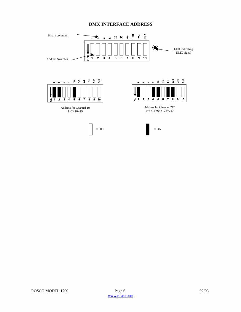
Setting the address: To set the DMX address, use the dip switches located on the DMXinterface. The dip switches are based on the binary system, so the channel number must first beconverted to a binary number. (See illustration). When the dip switch is in the down position, itis “on”. When there is a valid DMX signal, the LED next to the dip switches will light. NOTE:The Rosco Model 1700 uses one DMX channel.
Operating the unit: Turn the power switch (I/O) on. If the DMX interface is plugged in themachine will automatically start to heat up. This will be indicated by the red LED on the top ofthe machine. When the machine reaches proper operating temperature, the green LED on topof the machine will light. When the proper DMX channel is given a non-zero value, themachine will make fog. The fog volume will be proportional to the value of the channel setting.
Test Button: There is a red momentary test button located on the DMX Interface. This buttonis operable if the machine is on and the DMX interface is plugged in. When the machine is atproper operating tempearture (as designated by the green LED on top of the machine),pressing the Test Button will momentarily make fog.
ROSCO MODEL 1700 Page 6 02/03www.rosco.com
DMX INTERFACE ADDRESS
Address Switches
LED indicatingDMX signal
Binary columns
Address for Channel 2171+8+16+64+128=217
Address for Channel 191+2+16=19
= OFF = ON
ROSCO MODEL 1700 Page 7 02/03www.rosco.com
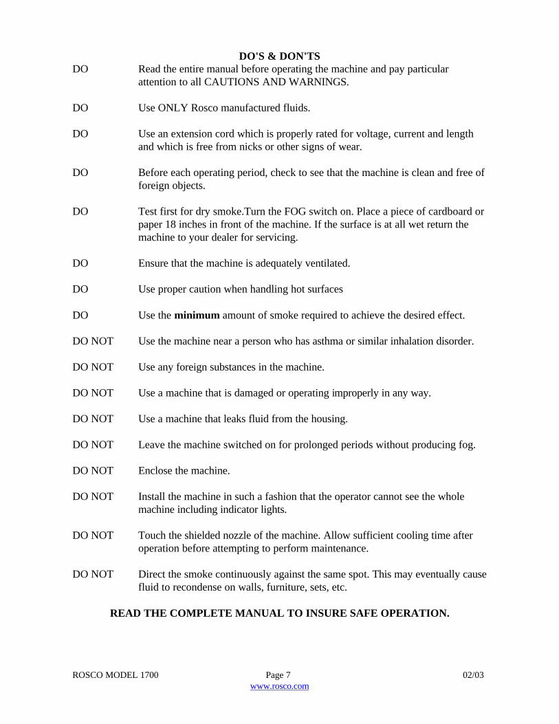
DO'S & DON'TSDO Read the entire manual before operating the machine and pay particular
attention to all CAUTIONS AND WARNINGS.
DO Use ONLY Rosco manufactured fluids.
DO Use an extension cord which is properly rated for voltage, current and lengthand which is free from nicks or other signs of wear.
DO Before each operating period, check to see that the machine is clean and free offoreign objects.
DO Test first for dry smoke.Turn the FOG switch on. Place a piece of cardboard orpaper 18 inches in front of the machine. If the surface is at all wet return themachine to your dealer for servicing.
DO Ensure that the machine is adequately ventilated.
DO Use proper caution when handling hot surfaces
DO Use the minimum amount of smoke required to achieve the desired effect.
DO NOT Use the machine near a person who has asthma or similar inhalation disorder.
DO NOT Use any foreign substances in the machine.
DO NOT Use a machine that is damaged or operating improperly in any way.
DO NOT Use a machine that leaks fluid from the housing.
DO NOT Leave the machine switched on for prolonged periods without producing fog.
DO NOT Enclose the machine.
DO NOT Install the machine in such a fashion that the operator cannot see the wholemachine including indicator lights.
DO NOT Touch the shielded nozzle of the machine. Allow sufficient cooling time afteroperation before attempting to perform maintenance.
DO NOT Direct the smoke continuously against the same spot. This may eventually causefluid to recondense on walls, furniture, sets, etc.
READ THE COMPLETE MANUAL TO INSURE SAFE OPERATION.
ROSCO MODEL 1700 Page 8 02/03www.rosco.com
MAINTENANCE
1. The main fuse of the ROSCO MODEL 1700 smoke machine is located on the circuit cardinside the machine. NOTE: Be sure to check the specifications when replacing any fuses.
WARNING: DISCONNECT THE ROSCO MODEL 1700 FROM POWER BEFORECHECKING OR REPLACING THE FUSE. FAILURE TO DO SO COULD BEHAZARDOUS AND RESULT IN AN ELECTRICAL SHOCK.
2. After every operation, the siphon hose should be removed from the external reservoir. Themachine should be turned on and fog produced. When there is no more fog coming out of themachine, the machine should be immediately turned off.
3. After every operation, only after the machine has cooled, it should be wiped with a cleandamp cloth or paper towel. This practice prevents the build up of dirt and dust which mayenter the machine and damage sensitive internal components. Do not use solvents for cleaning.Soap and water are effective.
4. Before and after the machine is stored for an extended period, the machine should beproperly cleaned. The best method for cleaning is using distilled or de-ionized water. To flushthe machine, turn it on and, when ready to use, put the fluid pick-up tube into a container ofdistilled or de-ionized water. Run the water through the machine and flush for three minutes.The tube should be removed from the water and the machine run until nothing comes out ofthe nozzle. The machine should be immediately turned off.
5. During use, operation of all switches and indicator lights should be monitored. Lights thatblink or flicker when they should be on or off, for example, are an indication of problems in themachine's circuitry.
FOG DISTRIBUTION
The fog distribution in an enclosed area depends on air flow and temperature. Natural airmovement, air conditioning and other ventilation systems will affect movement of the fog. Testunder realistic conditions before using. If a space must be filled very quickly, move the machineup and down and side to side. To conduct fog to particular areas, use a hose adaptor andducting hose (see OPTIONAL ACCESSORIES). Make sure that there is an air space of 2-3inches between the nozzle and any ducting hose. Do not use ducting hose smaller than 4 inchdiameter. The ROSCO MODEL 1700 works properly only in a horizontal position. Do not tiltthe machine during operation.
ROSCO MODEL 1700 Page 9 02/03www.rosco.com
ROSCO OFFICES WORLDWIDE
If the machine fails and repairs are required, call or write the nearest Rosco office (listedbelow) or your local Rosco dealer.
UNITED STATESWorld HeadquartersRosco Laboratories, Inc.52 Harbor View AvenueStamford, CT 06902(203) 708-8900(800) 767-2669E-mail: [email protected]
Rosco Laboratories, Inc.1120 N. Citrus AvenueHollywood, CA 90038(323) 462-2233(800) 767-2652
Rosco Service Center1330 30th Street.Unit GSan Diego, CA 92154(619) 423-1985(800) 468-0114
CANADARosco Laboratories, Ltd.1271 Denison Street #66Markham, OntarioCanada L3R 4B5(905) 475-1400E-mail: [email protected]
UNITED KINGDOMRoscolab, Ltd.Blanchard WorksKangley Bridge RoadSydenham, LondonSE26 5AQ England(81) 659-2300E-mail: [email protected]
SPAIN & PORTUGALRosco Iberica, S.A.C/Perfumería, Nave 8P.I. La Mina28770 Colmenar ViejoMadrid, Spain(34) 918 473 900E-mail: [email protected]
AUSTRALIARosco Australia Pty Ltd.42 Sawyer LaneArtarmon 2064N.S.W. Australia(02)9906-6262E-mail: [email protected]
BRAZILRosco do Brasil Ltda.Rua Costa, 75CEP 01304-010Sao Paulo - SP, Brasil(011) 259-2111E-mail: [email protected]

ROSCO MODEL 1700 Page 10 02/03www.rosco.com
LIMITED WARRANTY
ROSCO LABORATORIES, INC. warrants to the original purchaser that the ROSCO MODEL1700 will be free from original defects in workmanship and material for a period of twelve monthsfrom the date of purchase. During the warranty period, machines will be repaired or replaced atthe option of ROSCO.
The warranty does not extend to any parts of the ROSCO MODEL 1700 that have been subjectto misuse or accident. Neither does the warranty cover any machine that has been opened,modified or repaired other than by ROSCO or its designated repair station.
The warranty will not apply if procedures described in the Operations Manual are not followed. Itis the user's obligation to clean and maintain the ROSCO MODEL 1700 according to theseinstructions, and to follow acceptable practices for handling electrical devices.
NOTE: USE OF ANY FLUID OTHER THAN A ROSCO BRAND FLUID WILL VOIDTHE WARRANTY.
STORAGE AND SHIPMENT
If you do not anticipate using your machine for an extended period, prepare your machine forstorage as follows:
1. Perform maintenance as outlined in "Maintenance" section.
2. Wipe the outside of the machine clean.
3. Store in a sealed cardboard box.
4. Whenever the unit is shipped, considerable care should be taken in packing to avoid damage intransit.
ROSCO MODEL 1700 Page 11 02/03www.rosco.com
ROSCO MODEL 1700TECHNICAL SPECIFICATIONS
POWER REQUIREMENTS120 volts, 60 Hz., 12 amps240 volts, 50 Hz., 5.2 amps
PARTICLE SIZE0.25-60 microns
DIMENSIONSHeight: 8.5 in. (21.6 cm)Width: 9.75 in. (24.8 cm)Length: 19.5 in. (49.5 cm)
WEIGHT22.5 lb. (10.3 kg)
REMOTE CONTROLVolume ControlSequencers
On time: 2-18 secondsOff time: 2-18 seconds
MAX. FLUID CONSUMPTION3.6 liters/hour (60 ml/min.)
FUSE12.5/120v
OPTIONAL ACCESSORIESDMX INTERFACEAllows the machine to be operated from a lighting control console.
HOSE ADAPTORMetal frame that connects ducting hose to machineDimensions: 4 in. (10.2 cm) x 6.75 in. (17.14 cm)
DUCTING HOSEFlexible, plastic hose, connects to hose adaptor for ducting of fogDimensions: 4 in. (10.2 cm) x 25 ft. (7.62 m)
ROSCO MODEL 1700 Page 12 02/03www.rosco.com
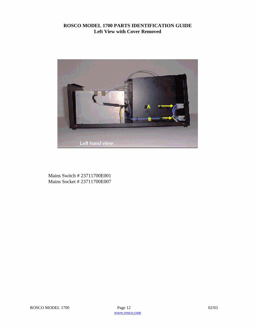
ROSCO MODEL 1700 PARTS IDENTIFICATION GUIDELeft View with Cover Removed
Mains Switch # 23711700E001Mains Socket # 23711700E007
ROSCO MODEL 1700 Page 13 02/03www.rosco.com
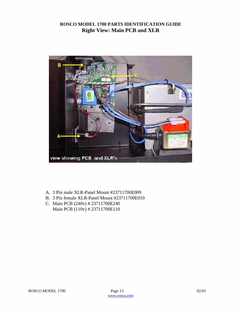
ROSCO MODEL 1700 PARTS IDENTIFICATION GUIDERight View: Main PCB and XLR
A. 3 Pin male XLR-Panel Mount #23711700E009B. 3 Pin female XLR-Panel Mount #23711700E010C. Main PCB (240v) # 23711700E240
Main PCB (110v) # 23711700E110
ROSCO MODEL 1700 Page 14 02/03www.rosco.com
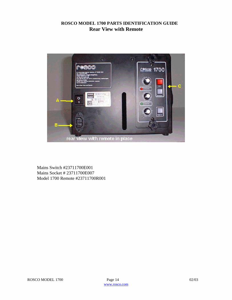
ROSCO MODEL 1700 PARTS IDENTIFICATION GUIDERear View with Remote
Mains Switch #23711700E001Mains Socket # 23711700E007Model 1700 Remote #23711700R001
ROSCO MODEL 1700 Page 15 02/03www.rosco.com
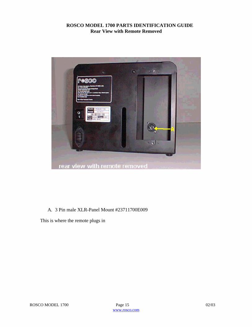
ROSCO MODEL 1700 PARTS IDENTIFICATION GUIDERear View with Remote Removed
A. 3 Pin male XLR-Panel Mount #23711700E009
This is where the remote plugs in
ROSCO MODEL 1700 Page 16 02/03www.rosco.com
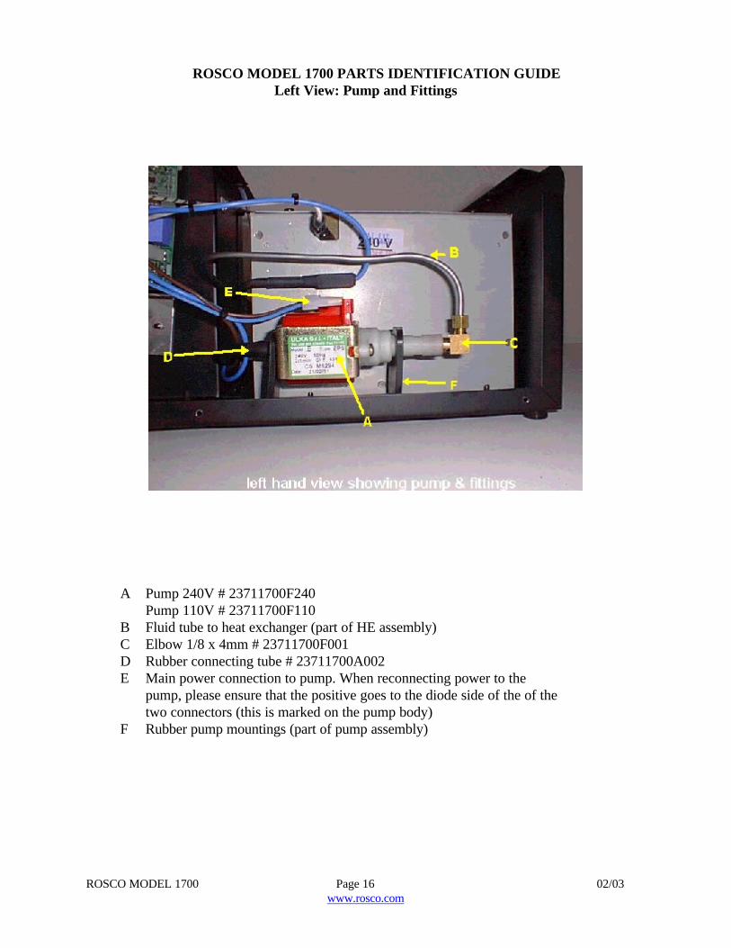
ROSCO MODEL 1700 PARTS IDENTIFICATION GUIDELeft View: Pump and Fittings
A Pump 240V # 23711700F240Pump 110V # 23711700F110
B Fluid tube to heat exchanger (part of HE assembly)C Elbow 1/8 x 4mm # 23711700F001D Rubber connecting tube # 23711700A002E Main power connection to pump. When reconnecting power to the
pump, please ensure that the positive goes to the diode side of the of thetwo connectors (this is marked on the pump body)
F Rubber pump mountings (part of pump assembly)
ROSCO MODEL 1700 Page 17 02/03www.rosco.com
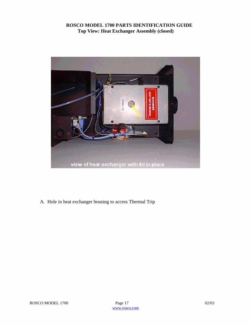
ROSCO MODEL 1700 PARTS IDENTIFICATION GUIDETop View: Heat Exchanger Assembly (closed)
A. Hole in heat exchanger housing to access Thermal Trip
ROSCO MODEL 1700 Page 18 02/03www.rosco.com
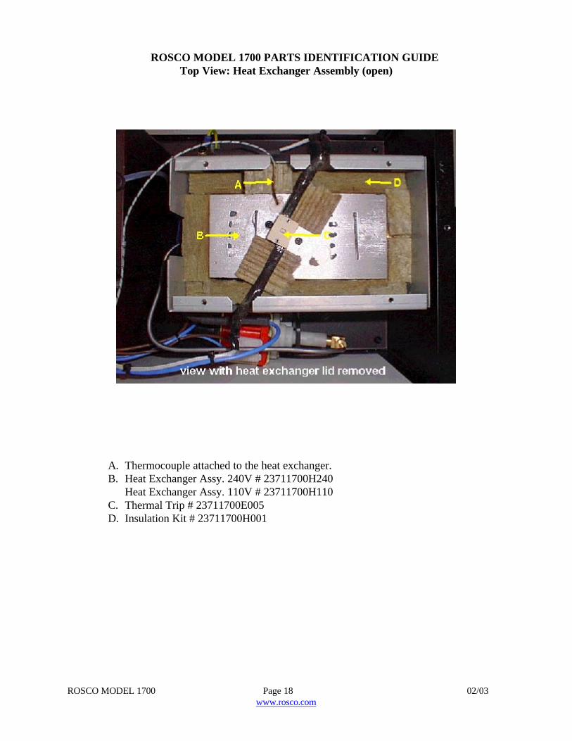
ROSCO MODEL 1700 PARTS IDENTIFICATION GUIDETop View: Heat Exchanger Assembly (open)
A. Thermocouple attached to the heat exchanger.B. Heat Exchanger Assy. 240V # 23711700H240
Heat Exchanger Assy. 110V # 23711700H110C. Thermal Trip # 23711700E005D. Insulation Kit # 23711700H001
ROSCO MODEL 1700 Page 19 02/03www.rosco.com
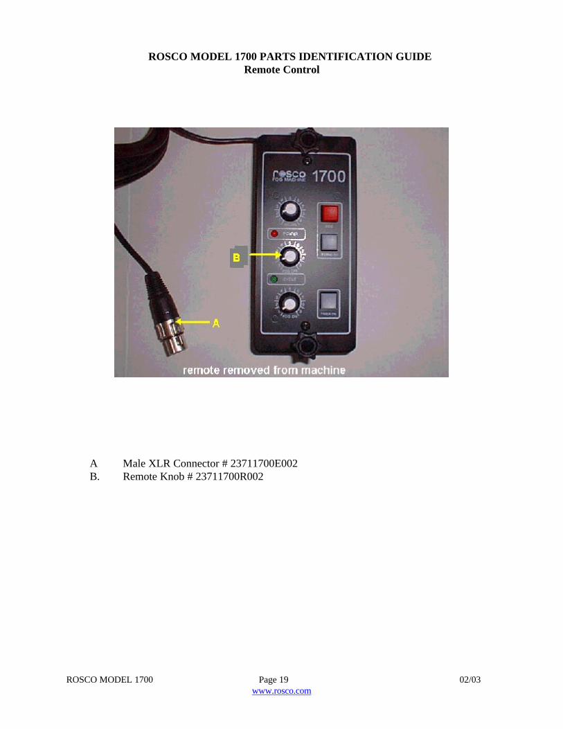
ROSCO MODEL 1700 PARTS IDENTIFICATION GUIDERemote Control
A Male XLR Connector # 23711700E002B. Remote Knob # 23711700R002
ROSCO MODEL 1700 Page 20 02/03www.rosco.com
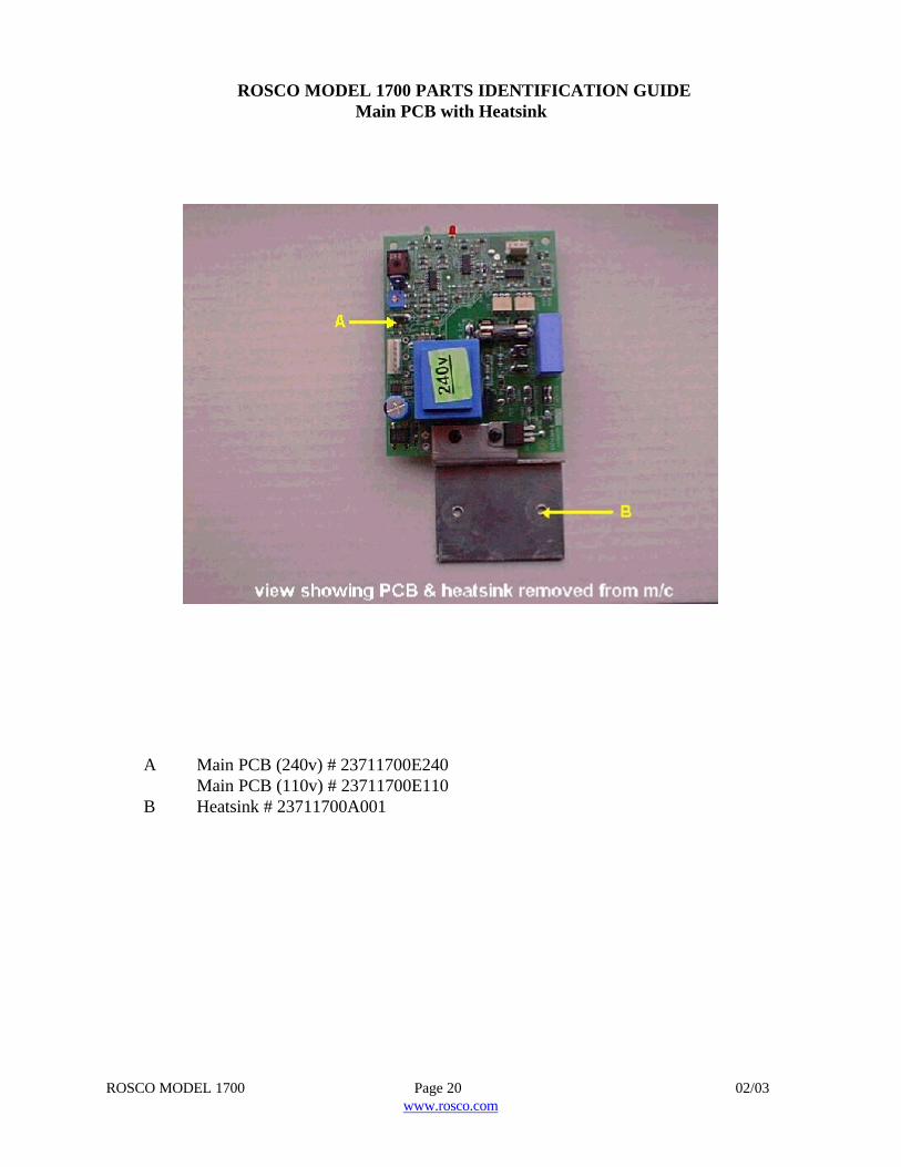
ROSCO MODEL 1700 PARTS IDENTIFICATION GUIDEMain PCB with Heatsink
A Main PCB (240v) # 23711700E240Main PCB (110v) # 23711700E110
B Heatsink # 23711700A001
ROSCO MODEL 1700 Page 21 02/03www.rosco.com
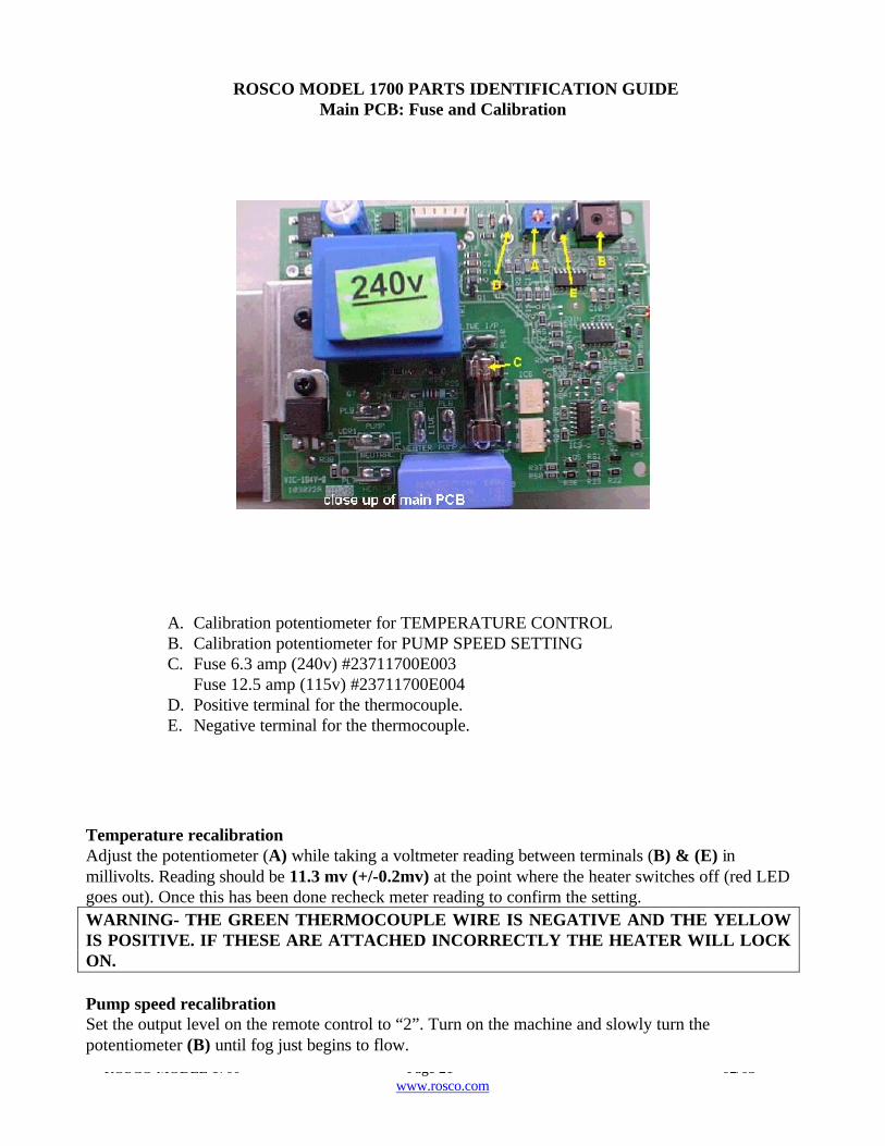
ROSCO MODEL 1700 PARTS IDENTIFICATION GUIDEMain PCB: Fuse and Calibration
A. Calibration potentiometer for TEMPERATURE CONTROLB. Calibration potentiometer for PUMP SPEED SETTINGC. Fuse 6.3 amp (240v) #23711700E003
Fuse 12.5 amp (115v) #23711700E004D. Positive terminal for the thermocouple.E. Negative terminal for the thermocouple.
Temperature recalibrationAdjust the potentiometer (A) while taking a voltmeter reading between terminals (B) & (E) inmillivolts. Reading should be 11.3 mv (+/-0.2mv) at the point where the heater switches off (red LEDgoes out). Once this has been done recheck meter reading to confirm the setting.WARNING- THE GREEN THERMOCOUPLE WIRE IS NEGATIVE AND THE YELLOWIS POSITIVE. IF THESE ARE ATTACHED INCORRECTLY THE HEATER WILL LOCKON.
Pump speed recalibrationSet the output level on the remote control to “2”. Turn on the machine and slowly turn thepotentiometer (B) until fog just begins to flow.
ROSCO MODEL 1700 Page 22 02/03www.rosco.com
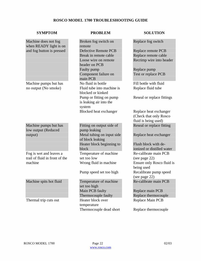
ROSCO MODEL 1700 TROUBLESHOOTING GUIDE
SYMPTOM
Machine does not fogwhen READY light is onand fog button is pressed
Machine pumps but hasno output (No smoke)
Machine pumps but haslow output (Reducedoutput)
Fog is wet and leaves atrail of fluid in front of themachine
Machine spits hot fluid
Thermal trip cuts out
PROBLEM
Broken fog switch onremoteDefective Remote PCBBreak in remote cableLoose wire on remoteheader on PCBFaulty pumpComponent failure onmain PCBNo fluid in bottleFluid tube into machine isblocked or kinkedPump or fitting on pumpis leaking air into thesystemBlocked heat exchanger
Fitting on output side ofpump leakingMetal tubing on input sideof block leakingHeater block beginning toblockTemperature of machineset too lowWrong fluid in machine
Pump speed set too high
Temperature of machineset too highMain PCB faultyThermocouple faultyHeater block overtemperatureThermocouple dead short
SOLUTION
Replace fog switch
Replace remote PCBReplace remote cableRecrimp wire into header
Replace pumpTest or replace PCB
Fill bottle with fluidReplace fluid tube
Reseal or replace fittings
Replace heat exchanger(Check that only Roscofluid is being used)Reseal or replace fitting
Replace heat exchanger
Flush block with de-ionized or distilled waterRe-calibrate main PCB(see page 22)Ensure only Rosco fluid isbeing usedRecalibrate pump speed(see page 22)Re-calibrate main PCB
Replace main PCBReplace thermocoupleReplace Main PCB
Replace thermocouple
ROSCO MODEL 1700 Page 23 02/03www.rosco.com
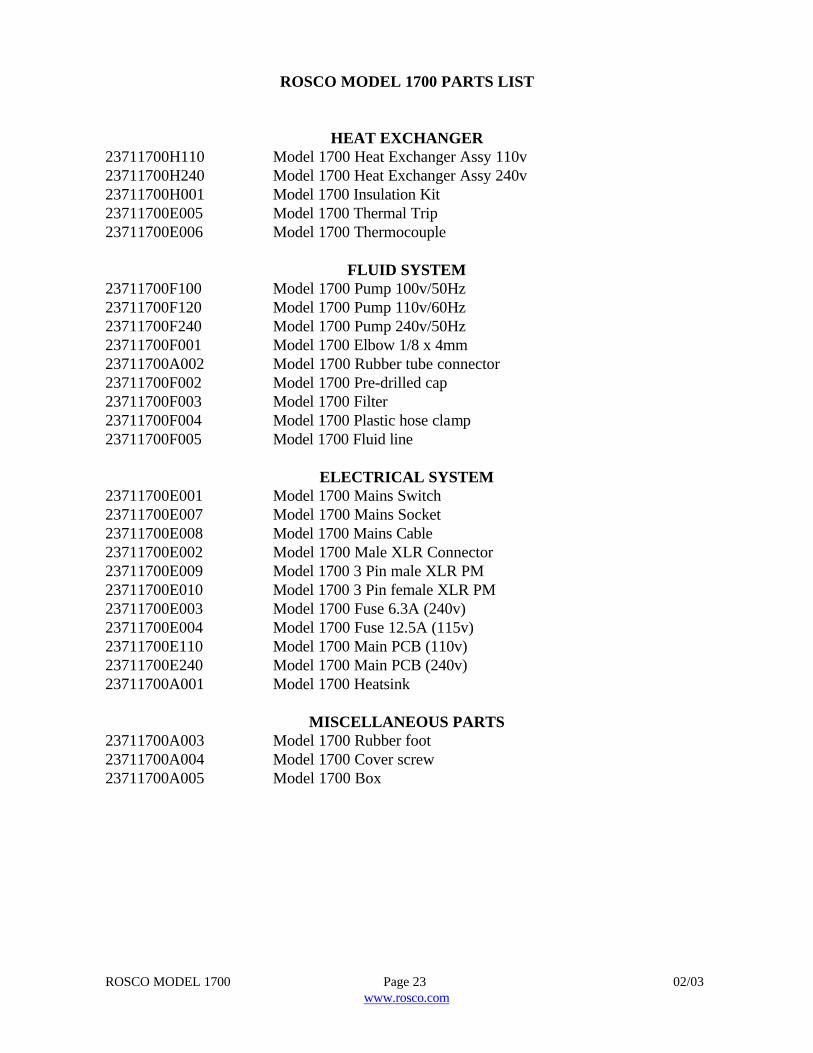
ROSCO MODEL 1700 PARTS LIST
HEAT EXCHANGER23711700H110 Model 1700 Heat Exchanger Assy 110v23711700H240 Model 1700 Heat Exchanger Assy 240v23711700H001 Model 1700 Insulation Kit23711700E005 Model 1700 Thermal Trip23711700E006 Model 1700 Thermocouple
FLUID SYSTEM23711700F100 Model 1700 Pump 100v/50Hz23711700F120 Model 1700 Pump 110v/60Hz23711700F240 Model 1700 Pump 240v/50Hz23711700F001 Model 1700 Elbow 1/8 x 4mm23711700A002 Model 1700 Rubber tube connector23711700F002 Model 1700 Pre-drilled cap23711700F003 Model 1700 Filter23711700F004 Model 1700 Plastic hose clamp23711700F005 Model 1700 Fluid line
ELECTRICAL SYSTEM23711700E001 Model 1700 Mains Switch23711700E007 Model 1700 Mains Socket23711700E008 Model 1700 Mains Cable23711700E002 Model 1700 Male XLR Connector23711700E009 Model 1700 3 Pin male XLR PM23711700E010 Model 1700 3 Pin female XLR PM23711700E003 Model 1700 Fuse 6.3A (240v)23711700E004 Model 1700 Fuse 12.5A (115v)23711700E110 Model 1700 Main PCB (110v)23711700E240 Model 1700 Main PCB (240v)23711700A001 Model 1700 Heatsink
MISCELLANEOUS PARTS23711700A003 Model 1700 Rubber foot23711700A004 Model 1700 Cover screw23711700A005 Model 1700 Box