Embed Size (px)
Citation preview
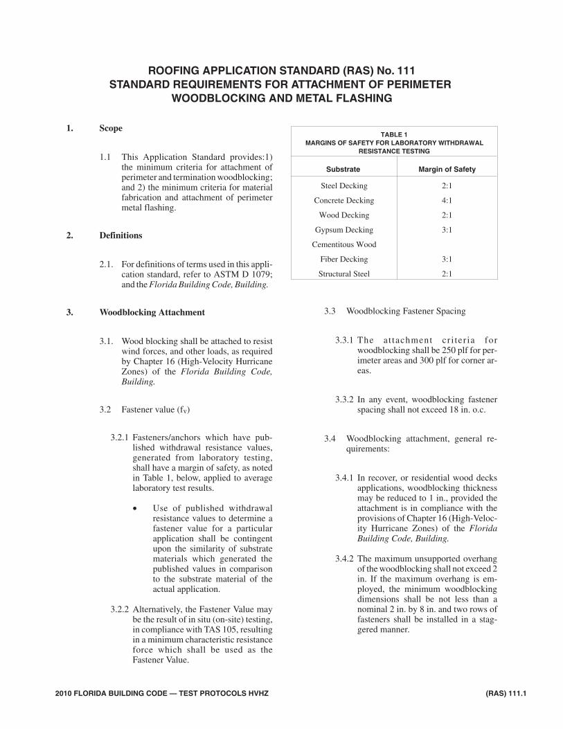
Scope1.
1.1 This Application Standard provides:1)the minimum criteria for attachment ofperimeter and termination woodblocking;and 2) the minimum criteria for materialfabrication and attachment of perimetermetal flashing.
Definitions2.
2.1. For definitions of terms used in this appli-cation standard, refer to ASTM D 1079;and the Florida Building Code, Building.
Woodblocking Attachment3.
3.1. Wood blocking shall be attached to resistwind forces, and other loads, as requiredby Chapter 16 (High-Velocity HurricaneZones) of the Florida Building Code,Building.
3.2 Fastener value (fv)
3.2.1 Fasteners/anchors which have pub-lished withdrawal resistance values,generated from laboratory testing,shall have a margin of safety, as notedin Table 1, below, applied to averagelaboratory test results.
• Use of published withdrawalresistance values to determine afastener value for a particularapplication shall be contingentupon the similarity of substratematerials which generated thepublished values in comparisonto the substrate material of theactual application.
3.2.2 Alternatively, the Fastener Value maybe the result of in situ (on-site) testing,in compliance with TAS 105, resultingin a minimum characteristic resistanceforce which shall be used as theFastener Value.
3.3 Woodblocking Fastener Spacing
3.3.1 The at tachment cr i ter ia forwoodblocking shall be 250 plf for per-imeter areas and 300 plf for corner ar-eas.
3.3.2 In any event, woodblocking fastenerspacing shall not exceed 18 in. o.c.
3.4 Woodblocking attachment, general re-quirements:
3.4.1 In recover, or residential wood decksapplications, woodblocking thicknessmay be reduced to 1 in., provided theattachment is in compliance with theprovisions of Chapter 16 (High-Veloc-ity Hurricane Zones) of the FloridaBuilding Code, Building.
3.4.2 The maximum unsupported overhangof the woodblocking shall not exceed 2in. If the maximum overhang is em-ployed, the minimum woodblockingdimensions shall be not less than anominal 2 in. by 8 in. and two rows offasteners shall be installed in a stag-gered manner.
2010 FLORIDA BUILDING CODE — TEST PROTOCOLS HVHZ (RAS) 111.1
ROOFING APPLICATION STANDARD (RAS) No. 111STANDARD REQUIREMENTS FOR ATTACHMENT OF PERIMETER
WOODBLOCKING AND METAL FLASHING
TABLE 1MARGINS OF SAFETY FOR LABORATORY WITHDRAWAL
RESISTANCE TESTING
Substrate Margin of Safety
Steel Decking 2:1
Concrete Decking 4:1
Wood Decking 2:1
Gypsum Decking 3:1
Cementitous Wood
Fiber Decking 3:1
Structural Steel 2:1
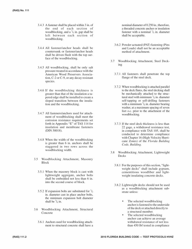
3.4.3 A fastener shall be placed within 3 in. ofthe end of each section ofwoodblocking, and a 1/4 in. gap shall beleft between each section ofwoodblocking.
3.4.4 All fastener/anchor heads shall becountersunk or fastener/anchor headsshall be driven flush with the top sur-face of the woodblocking.
3.4.5 All woodblocking, shall be only saltpressure treated in accordance with theAmerican Wood Preservers Associa-tion, C-2 or C-9, or any decay resistantspecies.
3.4.6 If the woodblocking thickness isgreater than that of the insulation a ta-pered edge shall be installed to create asloped transition between the insula-tion and the woodblocking.
3.4.7 All fasteners/anchors used for attach-ment of woodblocking shall meet thecorrosion resistance requirements setforth in Appendix “E” of TAS 114 forinsulation and membrane fasteners(DIN 50018).
3.4.8 When the width of the woodblockingis greater than 6 in. anchors shall bestaggered in two rows across thewoodblocking width.
3.5 Woodblocking Attachment, MasonryBlock
3.5.1 When the masonry block is cast withlightweight aggregate, anchor boltsshall be embedded not less than 6 in.into the second course of block.
3.5.2 If expansion bolts are substituted for 1/2
in. diameter cast in place anchor bolts,the minimum expansion bolt diametershall be 3/8 in.
3.6 Woodblocking Attachment, StructuralConcrete
3.6.1 Anchors used for woodblocking attach-ment to structural concrete shall have a
nominal diameter of 0.250 in.; therefore,a threaded concrete anchor or insulationfastener with a nominal 1/4 in. diametershall be acceptable.
3.6.2 Powder actuated (PAT) fastening (Pinsand Loads) shall not be an acceptablemethod of attachment.
3.7 Woodblocking Attachment, Steel Deck-ing
3.7.1 All fasteners shall penetrate the topflange of the steel deck.
3.7.2 When woodblocking is attached parallelto the deck flutes, the steel decking shallbe mechanically attached to the struc-tural steel with minimum 1/4 in. diameterself-tapping or self-drilling fastenerswith a minimum 5/8 in. diameter bearingwasher, at a maximum spacing of sevenfeet o.c. prior to the attachment of thewoodblocking.
3.7.3 If the steel deck thickness is less than22 gage, a withdrawal resistance test,in compliance with TAS 105, shall beconducted to determine compliancewith Chapter 16 (High-Velocity Hurri-cane Zones) of the Florida BuildingCode, Building.
3.8 Woodblocking Attachment, LightweightDecks
3.8.1 For the purposes of this section, “light-weight decks” shall include gypsum,cementitious woodfiber and light-weight insulating concrete decks.
3.8.2 Lightweight decks should not be usedas a woodblocking attachment sub-strate unless:
• The selected woodblockinganchor is fastened to the undersideof the deck or attached directly toa structural member.
• The selected woodblockinganchor can achieve an averagewithdrawal resistance of not lessthan 450 lbf tested in compliance
(RAS) 111.2 2010 FLORIDA BUILDING CODE — TEST PROTOCOLS HVHZ
(RAS) No. 111
with TAS 105.
3.8.3 Toggle bolts are not acceptablewoodblocking fasteners for any typedeck.
3.8.4 Fastener spacing for wood blockingshall not exceed 12 inches o.c.
Galvanic Action4.
4.1 Components shall be compatible to mini-mize the potential for galvanic corrosion.Galvanic corrosion will occur when dis-similar metals come into contact with anelectrolyte. An electrolyte is any nonme-tallic substance (especially liquid) thatwill conduct electric current. Water is anelectrolyte. Metals that are more elec-tro-positive (anodic or least noble) andwill corrode more easily are at one end ofthe scale. Those that are more elec-tro-negative (cathodic are more 'noble')and are more corrosion resistant are at theother end of the scale.
4.2 Common metals used in metal roof con-struction in order of least noble to morenoble are as follows:
• Anodic (least noble)• Magnesium• Magnesium Alloys• Zinc• Galvanized Coated Steel• Aluminum 1100• Alclad• Cadmium• Mild Steel• Wrought Iron• Cast Iron• 13 percent Chromium Stainless
Steel (Type 410 active.)• 18-8 Stainless Steel (Type 304 ac-
tive.)• 18-12-3 Stainless Steel (Type 316
active.)• Lead / Tin Solder• Lead• Tin• Muntz Metal• Manganese Bronze• Naval Brass• Nickel (active)• 76 Ni-16 Cr-7 Fe alloy (active)
• 60 Ni-30 Mo-6 Fe-1 Mn• Yellow Brass• Admiralty Brass• Aluminum Brass• Red Brass• Copper• Silicone Bronze• 70:30 Cupro Nickel• G-Bronze• M-Bronze• Silver Solder• Nickel (passive)• 76 Ni-16 Cr-7 Fe alloy (passive)• Monel• 13 % Chromium Stainless Steel
(Type 410 passive)• Titanium• 18-8 Stainless Steel (Type 304 pas-
sive)• 18-12-3 Stainless Steel (Type 316
passive)• Silver• Graphite• Gold• Platinum• Cathodic (more noble)
4.3 To reduce the occurrence of galvanic cor-rosion, the following steps shall be taken:
• Do not place metals far apart in thescale in contact with each other.Fasteners shall be of compatible ma-terials.
• The more noble (cathodic) metalmay be coated with a suitable paintor non-metallic coating.
• Do not design drainage from a cath-odic to anodic metal even if materi-als do not make contact. The waterwill conduct electrical current be-tween the two materials.
• Galvanized nails shall not be used toattach copper metal.
4.4 Flashing gages:
4.4.1 Table 2 lists material thickness re-quirements based on edge metal com-ponent dimensions for roof mean
(RAS) No. 111
2010 FLORIDA BUILDING CODE — TEST PROTOCOLS HVHZ (RAS) 111.3
height less than 54 ft. For roof meanheight of 54 ft. or greater flashing ter-minations shall be designed by a pro-fessional engineer or registeredarchitect proficient in roofing design.Calculations in compliance Chapter 16(High-Velocity Hurricane Zones) ofthe Florida Building Code, Buildingshall be submitted with Section II ofthe Uniform Building PermitApplication to the building official forreview.
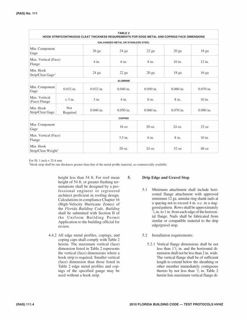
4.4.2 All edge metal profiles, copings, andcoping caps shall comply with Table 2herein. The maximum vertical (face)dimension listed in Table 2 representsthe vertical (face) dimensions where ahook strip is required. Smaller vertical(face) dimension than those listed inTable 2 edge metal profiles and cop-ings of the specified gauge may beused without a hook strip.
Drip Edge and Gravel Stop5.
5.1 Minimum attachment shall include hori-zontal flange attachment with approvedminimum 12 ga. annular ring shank nails ata spacing not to exceed 4 in. o.c. in a stag-gered pattern. Rows shall be approximately3/4 in. to 1 in. from each edge of the horizon-tal flange. Nails shall be fabricated fromsimilar or compatible material to the dripedge/gravel stop.
5.2 Installation requirements:
5.2.1 Vertical flange dimensions shall be notless than 11/2 in. and the horizontal di-mension shall not be less than 2 in. wide.The vertical flange shall be of sufficientlength to extend below the sheathing orother member immediately contiguousthereto by not less than 1/2 in. Table 2herein lists maximum vertical flange di-
(RAS) 111.4 2010 FLORIDA BUILDING CODE — TEST PROTOCOLS HVHZ
(RAS) No. 111
TABLE 2HOOK STRIP/CONTINUOUS CLEAT THICKNESS REQUIREMENTS FOR EDGE METAL AND COPINGS FACE DIMENSIONS
GALVANIZED METAL OR STAINLESS STEEL
Min. ComponentGage
26 ga 24 ga 22 ga 20 ga 18 ga
Max. Vertical (Face)Flange
4 in. 6 in. 8 in. 10 in. 12 in.
Min. HookStrip/Cleat Gage1 24 ga 22 ga 20 ga 18 ga 16 ga
ALUMINIM
Min. ComponentGage 0.032 in. 0.032 in. 0.040 in. 0.050 in. 0.060 in. 0.070 in.
Max. Vertical(Face) Flange < 3 in. 3 in. 4 in. 6 in. 8 in. 10 in.
Min. HookStrip/Cleat Gage
NotRequired
0.040 in. 0.050 in. 0.060 in. 0.070 in. 0.080 in.
COPPER
Min. ComponentGage
16 oz 20 oz. 24 oz. 32 oz
Max. Vertical (Face)Flange
3.5 in. 6 in. 8 in. 10 in.
Min. HookStrip/Cleat Weight1 20 oz. 24 oz. 32 oz 48 oz
For SI: 1 inch = 25.4 mm.1Hook strip shall be one thickness greater than that of the metal profile material, as commercially available.
mensions for various drip edge/gravelstop materials.
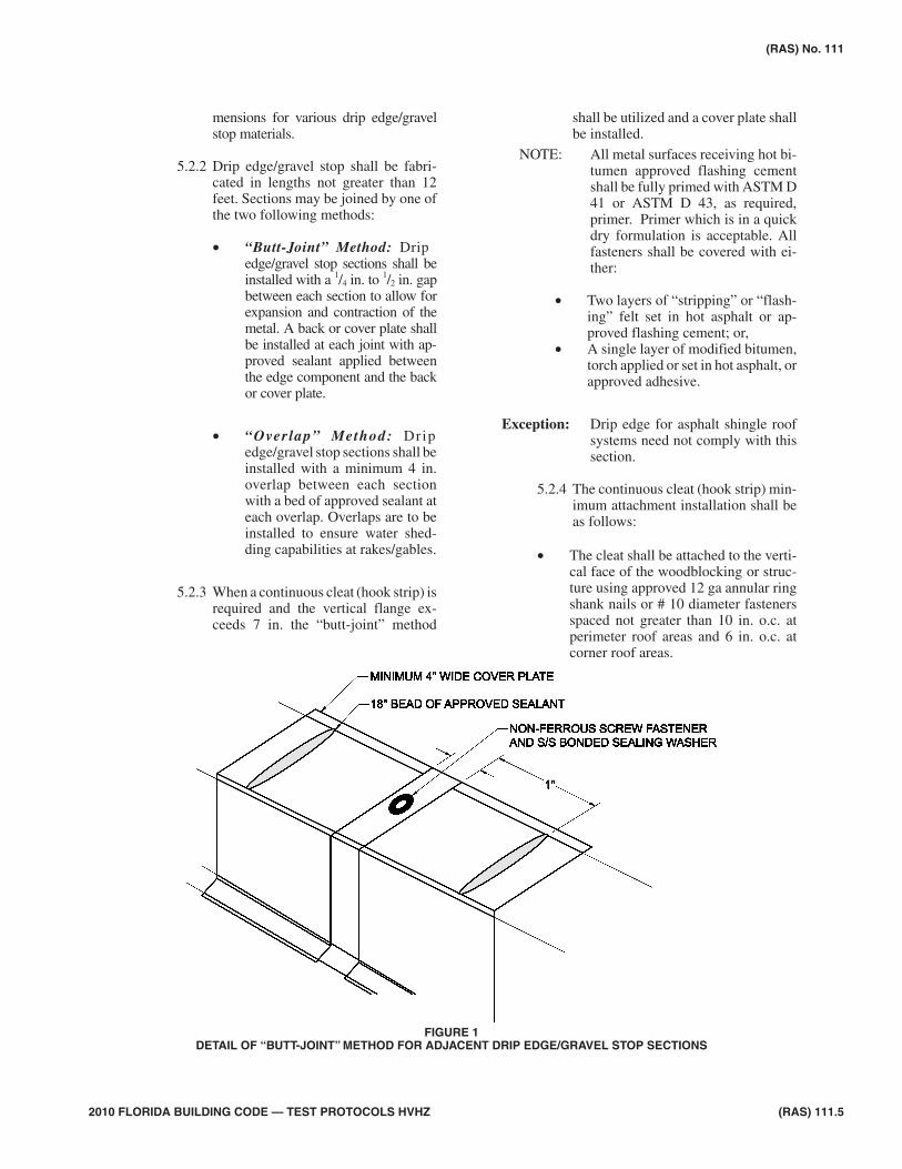
5.2.2 Drip edge/gravel stop shall be fabri-cated in lengths not greater than 12feet. Sections may be joined by one ofthe two following methods:
• “Butt-Joint” Method: Dripedge/gravel stop sections shall beinstalled with a 1/4 in. to 1/2 in. gapbetween each section to allow forexpansion and contraction of themetal. A back or cover plate shallbe installed at each joint with ap-proved sealant applied betweenthe edge component and the backor cover plate.
• “Overlap” Method: Dripedge/gravel stop sections shall beinstalled with a minimum 4 in.overlap between each sectionwith a bed of approved sealant ateach overlap. Overlaps are to beinstalled to ensure water shed-ding capabilities at rakes/gables.
5.2.3 When a continuous cleat (hook strip) isrequired and the vertical flange ex-ceeds 7 in. the “butt-joint” method
shall be utilized and a cover plate shallbe installed.
NOTE: All metal surfaces receiving hot bi-tumen approved flashing cementshall be fully primed with ASTM D41 or ASTM D 43, as required,primer. Primer which is in a quickdry formulation is acceptable. Allfasteners shall be covered with ei-ther:
• Two layers of “stripping” or “flash-ing” felt set in hot asphalt or ap-proved flashing cement; or,
• A single layer of modified bitumen,torch applied or set in hot asphalt, orapproved adhesive.
Exception: Drip edge for asphalt shingle roofsystems need not comply with thissection.
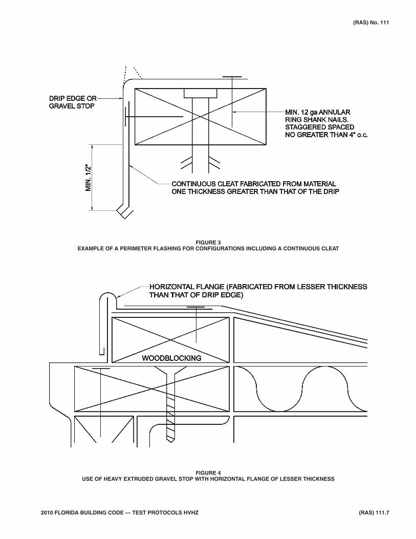
5.2.4 The continuous cleat (hook strip) min-imum attachment installation shall beas follows:
• The cleat shall be attached to the verti-cal face of the woodblocking or struc-ture using approved 12 ga annular ringshank nails or # 10 diameter fastenersspaced not greater than 10 in. o.c. atperimeter roof areas and 6 in. o.c. atcorner roof areas.
2010 FLORIDA BUILDING CODE — TEST PROTOCOLS HVHZ (RAS) 111.5
(RAS) No. 111
FIGURE 1DETAIL OF “BUTT-JOINT” METHOD FOR ADJACENT DRIP EDGE/GRAVEL STOP SECTIONS
• Nails shall be fabricated from similar orcompatible material to that of the contin-uous cleat, and shall be of sufficientlength to penetrate the substrate by notless than 11/4 in. and shall have a mini-mum head size of 5/16 in.
• Nylon or plastic anchors shall not beacceptable.
5.2.5 Notwithstanding the minimum attach-ment criteria noted herein, metal edgesystems of any dimension may betested in compliance with TAS 111(A)and TAS 111 (B), the values fromwhich may be submitted with SectionII of the Uniform Building Permit ap-plication to the building official for re-view.
5.2.6 Heavy, extruded drip edge/gravel stopsections may be used provided a hori-zontal flange of a lesser thickness is in-corporated into the edge metalconfiguration (see Figure 4).
5.2.7 Where the drip edge/gravel stop formspart of a metal roof system, the follow-ing provisions apply:
• The drip edge/gravel stop shallbe secured to the profile metalsheetor structural members withsufficient anchors/fasteners toresist wind forces determined incompliance with Chapter 16(High-Veloci ty Hurr icaneZones) of the Florida BuildingCode, Building and in accor-dance with RAS 111and 133.
• All fasteners shall be fitted withminimum 5/8 in. o.c.bonded seal-ing washers, unlessotherwisenoted in the roofing assemblyProduct Approval.
• Continuous clips (hook strips)shall be required as noted in Ta-ble 2 herein.
(RAS) 111.6 2010 FLORIDA BUILDING CODE — TEST PROTOCOLS HVHZ
(RAS) No. 111
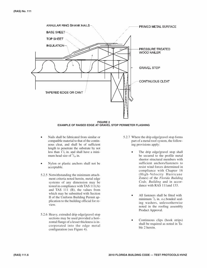
FIGURE 2EXAMPLE OF RAISED EDGE AT GRAVEL STOP PERIMETER FLASHING
(RAS) No. 111
2010 FLORIDA BUILDING CODE — TEST PROTOCOLS HVHZ (RAS) 111.7
FIGURE 3EXAMPLE OF A PERIMETER FLASHING FOR CONFIGURATIONS INCLUDING A CONTINUOUS CLEAT
FIGURE 4USE OF HEAVY EXTRUDED GRAVEL STOP WITH HORIZONTAL FLANGE OF LESSER THICKNESS
Metal Profiles, Copings, & Coping Caps6.
6.1 All metal profiles, copings, and copingcap attachments must resist wind inducedoutward and upward forces which attemptto lift or peel the edge system from its at-tachment points, in compliance withChapter 16 (High-Velocity HurricaneZones) of the Florida Building Code,Building.
6.2 The metal profiles, copings, and copingcaps and their attachments shall be de-signed to meet design pressures in com-pliance with Chapter 16 (High-VelocityHurricane Zones) of the Florida BuildingCode, Building and shall be tested in com-pliance with TAS 111(A), TAS 111(B)and TAS 111C to confirm compliance.
6.2.1 Criteria for vertical flange dimension,material type, thickness, and require-ments for use of a continuous cleat(hook strip) are noted in Table 2herein.
6.3 Installation Requirements
6.3.1 The vertical flange of metal profiles andcoping caps shall be of sufficient lengthto extend below wood blocking by notless than 1/2 in.
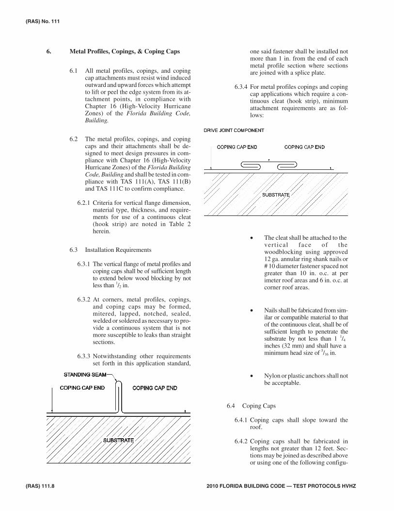
6.3.2 At corners, metal profiles, copings,and coping caps may be formed,mitered, lapped, notched, sealed,welded or soldered as necessary to pro-vide a continuous system that is notmore susceptible to leaks than straightsections.
6.3.3 Notwithstanding other requirementsset forth in this application standard,
one said fastener shall be installed notmore than 1 in. from the end of eachmetal profile section where sectionsare joined with a splice plate.
6.3.4 For metal profiles copings and copingcap applications which require a con-tinuous cleat (hook strip), minimumattachment requirements are as fol-lows:
• The cleat shall be attached to thevert ical face of thewoodblocking using approved12 ga. annular ring shank nails or# 10 diameter fastener spaced notgreater than 10 in. o.c. at perimeter roof areas and 6 in. o.c. atcorner roof areas.
• Nails shall be fabricated from sim-ilar or compatible material to thatof the continuous cleat, shall be ofsufficient length to penetrate thesubstrate by not less than 1 1/4
inches (32 mm) and shall have aminimum head size of 5/16 in.
• Nylon or plastic anchors shall notbe acceptable.
6.4 Coping Caps
6.4.1 Coping caps shall slope toward theroof.
6.4.2 Coping caps shall be fabricated inlengths not greater than 12 feet. Sec-tions may be joined as described aboveor using one of the following configu-
(RAS) 111.8 2010 FLORIDA BUILDING CODE — TEST PROTOCOLS HVHZ
(RAS) No. 111
rations which eliminate splice platesand overlaps.
6.4.2.1 Standing Seam Configuration
6.4.2.2 The Drive Configuration belowallows use of a thinner materialfor the drive joint componentsthan that of the coping sections.
Counter-flashing7.
7.1 For material and thickness requirementssee Table 2 herein. Alternatively, coun-ter-flashing manufacturers may obtainProduct Approval.
7.2 General Attachment Requirements
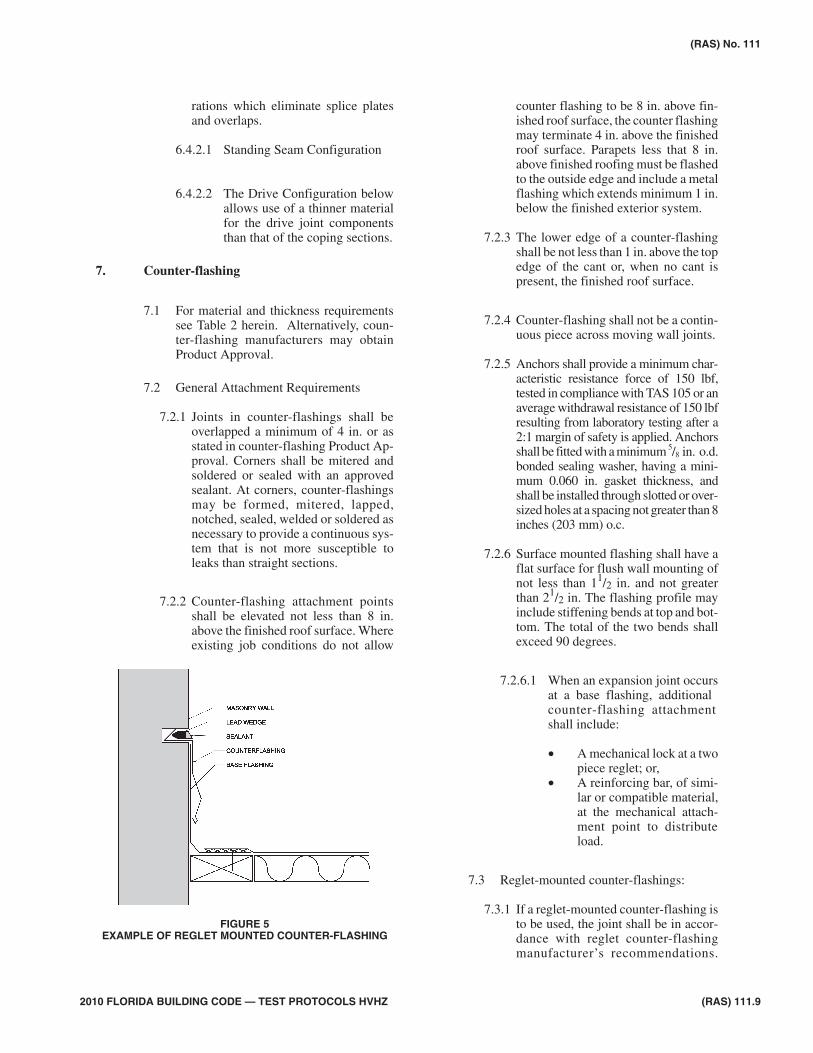
7.2.1 Joints in counter-flashings shall beoverlapped a minimum of 4 in. or asstated in counter-flashing Product Ap-proval. Corners shall be mitered andsoldered or sealed with an approvedsealant. At corners, counter-flashingsmay be formed, mitered, lapped,notched, sealed, welded or soldered asnecessary to provide a continuous sys-tem that is not more susceptible toleaks than straight sections.
7.2.2 Counter-flashing attachment pointsshall be elevated not less than 8 in.above the finished roof surface. Whereexisting job conditions do not allow
counter flashing to be 8 in. above fin-ished roof surface, the counter flashingmay terminate 4 in. above the finishedroof surface. Parapets less that 8 in.above finished roofing must be flashedto the outside edge and include a metalflashing which extends minimum 1 in.below the finished exterior system.
7.2.3 The lower edge of a counter-flashingshall be not less than 1 in. above the topedge of the cant or, when no cant ispresent, the finished roof surface.
7.2.4 Counter-flashing shall not be a contin-uous piece across moving wall joints.
7.2.5 Anchors shall provide a minimum char-acteristic resistance force of 150 lbf,tested in compliance with TAS 105 or anaverage withdrawal resistance of 150 lbfresulting from laboratory testing after a2:1 margin of safety is applied. Anchorsshall be fitted with a minimum 5/8 in. o.d.bonded sealing washer, having a mini-mum 0.060 in. gasket thickness, andshall be installed through slotted or over-sized holes at a spacing not greater than 8inches (203 mm) o.c.
7.2.6 Surface mounted flashing shall have aflat surface for flush wall mounting ofnot less than 11/2 in. and not greaterthan 21/2 in. The flashing profile mayinclude stiffening bends at top and bot-tom. The total of the two bends shallexceed 90 degrees.
7.2.6.1 When an expansion joint occursat a base flashing, additionalcounter-flashing attachmentshall include:
• A mechanical lock at a twopiece reglet; or,
• A reinforcing bar, of simi-lar or compatible material,at the mechanical attach-ment point to distributeload.
7.3 Reglet-mounted counter-flashings:
7.3.1 If a reglet-mounted counter-flashing isto be used, the joint shall be in accor-dance with reglet counter-flashingmanufacturer’s recommendations.
(RAS) No. 111
2010 FLORIDA BUILDING CODE — TEST PROTOCOLS HVHZ (RAS) 111.9
FIGURE 5EXAMPLE OF REGLET MOUNTED COUNTER-FLASHING
The counter-flashing may be held inplace by spring action wedges andsealant. Reglets shall not be cut intohollow cells of masonry walls or con-crete.
7.4 For surface mounted reglet-type coun-ter-flashing applications, the followingprovisions shall apply.
7.4.1 A bead of approved sealant shall be ap-plied at the top edge to create a water-proof seal. Sealant shall be installed inaccordance with the sealant manufac-turers published literature. Primershall be applied to the substrate mate-rial when recommended by the sealantmanufacturer. Sealant shall havetwo-point adhesion; to the reglet and tothe wall substrate for maximum seal-ant performance. Bond breaker orbacker rod shall be installed wherenecessary to create two-point adhe-sion. Refer to the sealant manufac-turer’s published literature for specifictypes of bond breaker of backer rods.
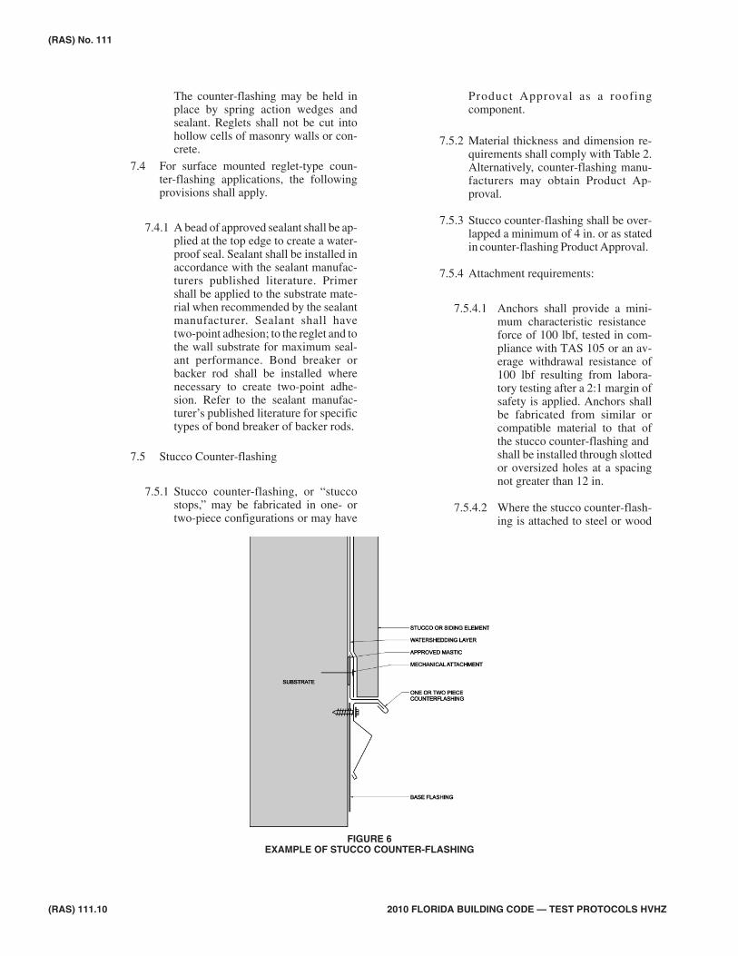
7.5 Stucco Counter-flashing
7.5.1 Stucco counter-flashing, or “stuccostops,” may be fabricated in one- ortwo-piece configurations or may have
Product Approval as a roofingcomponent.
7.5.2 Material thickness and dimension re-quirements shall comply with Table 2.Alternatively, counter-flashing manu-facturers may obtain Product Ap-proval.
7.5.3 Stucco counter-flashing shall be over-lapped a minimum of 4 in. or as statedin counter-flashing Product Approval.
7.5.4 Attachment requirements:
7.5.4.1 Anchors shall provide a mini-mum characteristic resistanceforce of 100 lbf, tested in com-pliance with TAS 105 or an av-erage withdrawal resistance of100 lbf resulting from labora-tory testing after a 2:1 margin ofsafety is applied. Anchors shallbe fabricated from similar orcompatible material to that ofthe stucco counter-flashing andshall be installed through slottedor oversized holes at a spacingnot greater than 12 in.
7.5.4.2 Where the stucco counter-flash-ing is attached to steel or wood
(RAS) 111.10 2010 FLORIDA BUILDING CODE — TEST PROTOCOLS HVHZ
(RAS) No. 111
FIGURE 6EXAMPLE OF STUCCO COUNTER-FLASHING
studs, attachment shall be ateach stud with a minimum #8 di-ameter fastener providing a min-imum characteristic resistanceforce of 150 lbf, tested in com-pliance with TAS 105 or an av-erage withdrawal resistance of150 lbf resulting from labora-tory testing after a 2:1 margin ofsafety is applied.
7.5.5 Stucco counter-flashing attachmentpoints shall be elevated not less than 8in. above the finished roof surface.Where existing job conditions do notallow stucco counter flashing to be 8inches above finished roof surface, thecounter flashing may terminate 4 in.above the finished roof surface.Parapets less than 8 in. above finishedroofing must be flashed to the outsideedge and include a metal flashingwhich extends minimum 1 in. belowthe finished exterior system.
7.5.6 The base water shedding layer behindthe stucco or siding element, where re-quired, shall terminate over top of thevertical leg of the stucco counter-flash-ing. Vertical leg of the stucco coun-ter-flashing shall be set in a bed of
approved mastic prior to mechanicalattachment or sealed in a three courseapplication of asphalt based masticand minimum 4 in. wide fiberglassmembrane following mechanical at-tachment (see Figure 6).
Metal Panel Flashings (Sill Flashings)8.
8.1.1 Material thickness and dimension re-quirements shall complywith Table 2herein. Alternatively, counter-flashingmanufacturers may obtain ProductApproval.
8.1.2 All metal wall panels shall be closedwith a foamed, or other type of com-pressible, closure strip approved foruse with the panel profile in the roofassembly Product Approval.
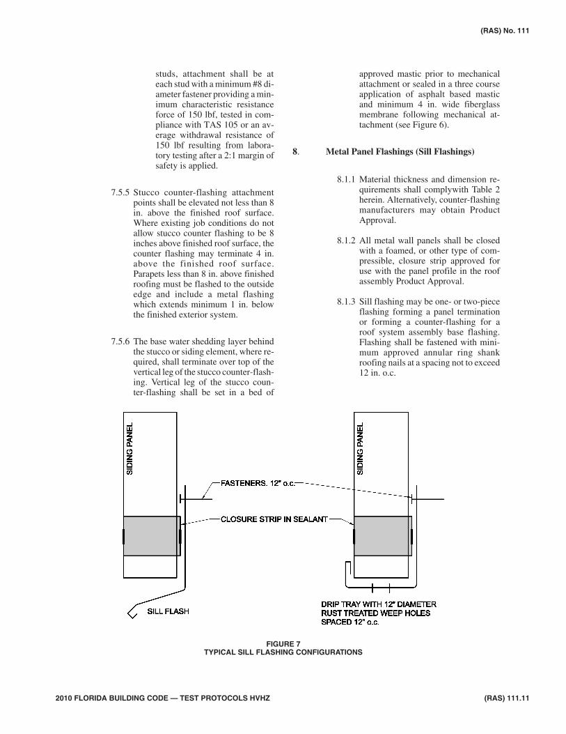
8.1.3 Sill flashing may be one- or two-pieceflashing forming a panel terminationor forming a counter-flashing for aroof system assembly base flashing.Flashing shall be fastened with mini-mum approved annular ring shankroofing nails at a spacing not to exceed12 in. o.c.
(RAS) No. 111
2010 FLORIDA BUILDING CODE — TEST PROTOCOLS HVHZ (RAS) 111.11
FIGURE 7TYPICAL SILL FLASHING CONFIGURATIONS
8.1.4 Weep trays shall have 1/2 in. min. diame-ter weep holes at a spacing not to exceed12 in. o.c. The weep holes shall betreated to prevent corrosion.
8.1.5 Metal wall panels may be terminatedwith similar flashing to those notedherein.
8.1.6 Typical sill flashing configurations arenoted in Figure 7, below.
Membrane Base Flashing9.
9.1 Minimum flashing shall consist of a baselayer of ASTM D 226, Type II; ASTM D4601, Type II; ASTM D 2626 base ply; orASTM D 4897, bonded to a primed verti-cal surface with type IV asphalt or an ap-proved cold adhesive or flashing cement.The base ply shall be covered with oneinterply of a like material to the base ply,bonded in Type IV asphalt or an approvedcold adhesive or flashing cement. The topflashing ply shall be a coated or granulesurfaced membrane of a materialcompatible with the base ply, bonded inType IV asphalt or an approved cold adhe-sive or flashing cement. The top flashing
ply shall have either a granular surface orbe coated with an approved aluminized oremulsion coating to meet the fire classifi-cation and to resist ultraviolet exposure.
9.2 Membrane base flashings shall be mechani-cally attached with a continuous metal ter-mination bar at 6 in. o.c to the vertical wall.Such termination bar shall be placed nomore than 11/2 in. down from the upper edgeof the membrane flashing. Membraneflashing shall terminate under a metal coun-ter flashing or be finished with a metal sur-face mounted reglet attached to the wall at aspacing not to exceed 8 in. on center. Thereglet shall be weatherproofed with a caulkbead of a suitable type to bond to both themetal reglet and the wall surface.
9.2.1 Anchors shall provide a minimumcharacteristic resistance force of 150lbf, tested in compliance with TAS 105or an average withdrawal resistance of150 lbf resulting from laboratory test-ing after a 2:1 margin of safety is ap-plied, and shall be installed throughslotted or oversized holes.
9.3 Membrane base flashings shall not be lessthan 8 in. above the finished roof surface.Where existing job conditions do not al-
(RAS) 111.12 2010 FLORIDA BUILDING CODE — TEST PROTOCOLS HVHZ
(RAS) No. 111
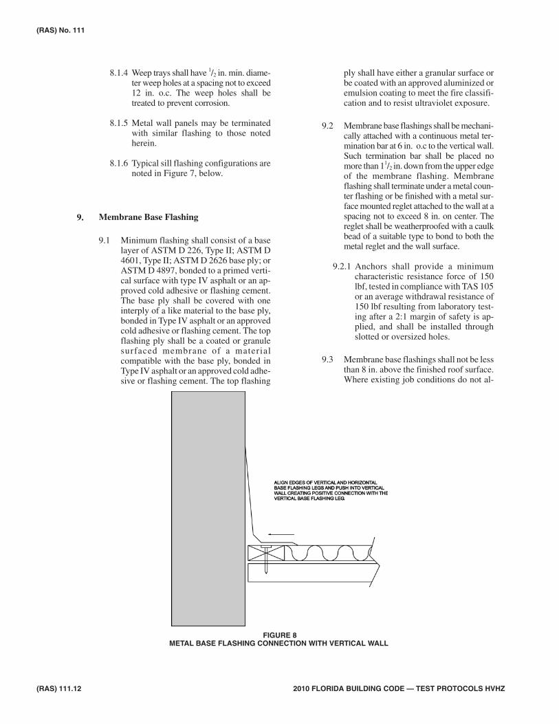
FIGURE 8METAL BASE FLASHING CONNECTION WITH VERTICAL WALL
low membrane base flashing to be 8 in.above finished roof surface, the counterflashing may terminate 4 in. above the fin-ished roof surface.
9.4 Membrane base flashings shall be contin-uous across the transition between thewall and roof.
9.5 All vertical junctions shall be providedwith a cant strip. Base flashing shall ex-tend a minimum of 8 in. above finishedroofing. Membranes shall not be angledup or down greater than 45 degrees whereexposed as part of the waterproofing layerunless specifically detailed in roof assem-blies published literature. Published de-tailed drawings shall be submitted withthe Uniform Building Permit Applicationto the building official for review.
9.6 In nonasphaltic single-ply roofing instal-lation, metal base flashings or perimeterdrip edge/gravel stop may be sealed withproprietary bonding methods, such ascoated metal for thermoplastic welding orcontact adhesives to bond membrane toprepared metal or other surfaces, in accor-dance with roof assemblies manufac-turer’s published literature. Metalterminations shall be secured in compli-
ance with the provisions herein and incompliance with Chapter 16 (High-Ve-locity Hurricane Zones) of the FloridaBuilding Code, Building.
9.7 Bituminous roofing systems may be ter-minated by multiply felts, modified bitu-men flashing, or in accordance with roofassemblies manufacturers published liter-ature. When asphaltic systems are bondedto metal, all metal shall be fully primedwith ASTM D 41 primer. Metal termina-tions shall be secured in compliance withthe provisions herein and in compliancewith Chapter 16 (High-Velocity Hurri-cane Zones) of the Florida BuildingCode, Building.
Termination Bars10.
10.1 Termination bars may be fabricated in a va-riety of shapes and profiles and should befabricated from materials having a highstiffness coefficient to evenly distribute theloads incurred on fasteners. Terminationbars shall be a minimum thickness of 1/8 in.
10.1.1 Holes in the termination bar shall beslotted or oversized to allow for di-mensional changes in the metal.
(RAS) No. 111
2010 FLORIDA BUILDING CODE — TEST PROTOCOLS HVHZ (RAS) 111.13
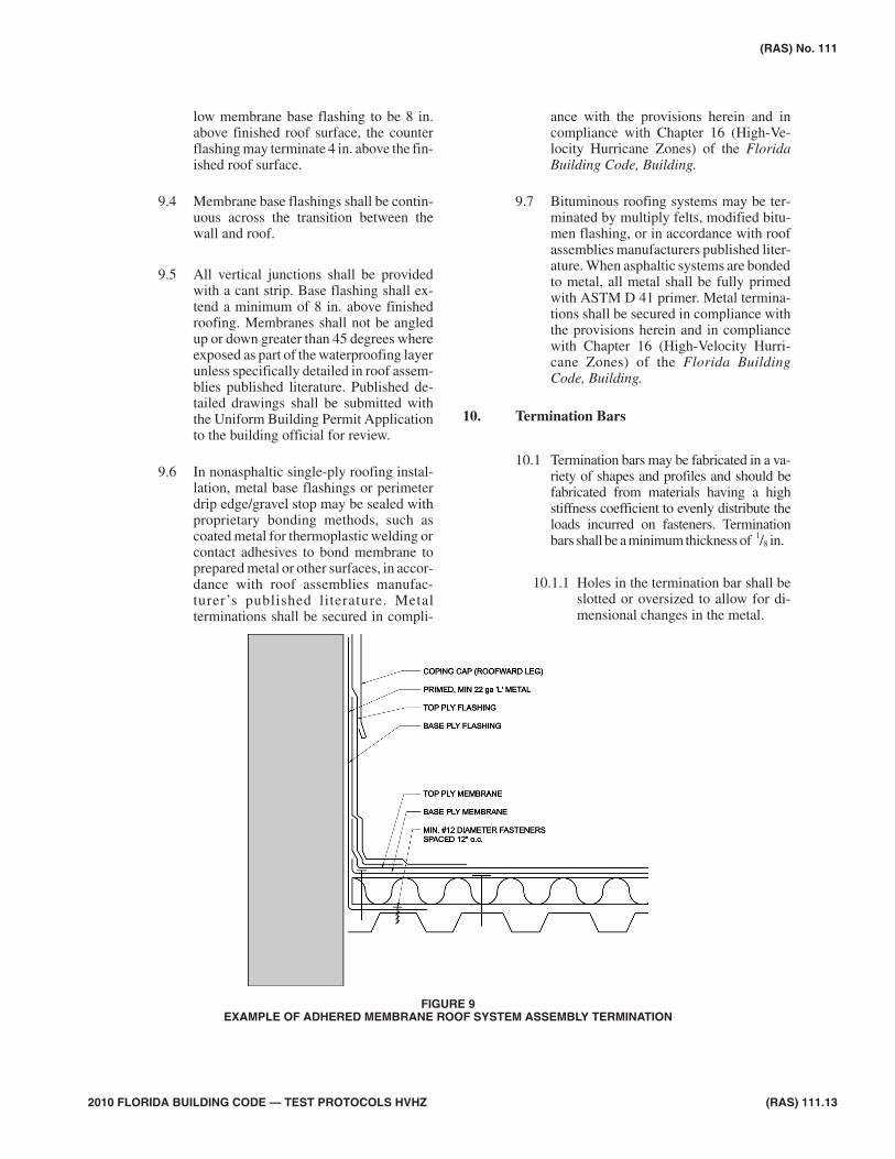
FIGURE 9EXAMPLE OF ADHERED MEMBRANE ROOF SYSTEM ASSEMBLY TERMINATION
10.1.2 All termination bars shall be testedfor corrosion resistance in compli-ance with Appendix E of TAS 114.(DIN 50018).
10.2 Minimum attachment requirements fortermination bars shall include the follow-ing.
• All termination bar fasteners or an-chors shall have a minimum 1/4 in. di-ameter. Anchors shall provide a minimum characteristic resistance force of180 lbf, tested in compliance withTAS 105 or an average withdrawal re-sistance of 180 lbf resulting from lab-oratory testing after a 2:1 margin ofsafety is applied, and shall be installedthrough slotted or oversized holes at aspacing not greater than 8 in. o.c. ex-cept as required in Section 9.2. At thediscretion of the building official afield withdrawal resistance test incompliance with TAS 105 may be re-quired to confirm performance.
• All termination bar fasteners or an-chors shall be fabricated from simi-lar or compatible material to that ofthe termination bar.
• A nonferrous metal bonded sealingwasher shall be installed under thehead of each fastener or anchor if thefastener head is left exposed. Fas-teners used in the installation of ter-mination bars to be covered bycounter flashing shall not requirebonded sealing washers.
• A continuous bead of approval seal-ant shall be applied under or at thetop edge of the termination bars,which are not covered by counterflashing.
• Nylon or plastic anchors shall not beacceptable.
Metal base flashing11.
11.1 Metal base flashings shall be fabricated atan angle slightly greater than 90 degreesto create an adequate connection betweenthe vertical leg and the adjoining verticalwall (see Figure 8).
11.2 Adhered single-ply or modified bitumenroof system assemblies not requiring acant may be terminated at a primed, mini-mum 22 ga “L” metal secured to the deck(see Figure 9).
11.3 Metal base flashings for metal roofingsystems shall comply with requirementsof RAS 133 and those listed herein.
Gutters12.
12.1 Gutters, down spouts, and hold downcomponents shall be secured to resist theload of gravity when full with rainwater inaddition to the design wind loads of Chap-ter 16 (High-Velocity Hurricane Zones)of the Florida Building Code, Building.
12.2 Gutters, and down spouts, shall be sized incompliance with Chapter 11 of theFlorida Building Code, Plumbing.
12.3 Gutters, down spouts, and hold downcomponents shall be constructed in accor-dance with the Sheet Metal and Air Con-di t ioning Contractors NationalAssociation, Inc. (SMACNA) Architec-tural Sheet Metal Manual, 5th edition. Inaddition to the following requirements:
12.3.1 Gutter joints shall be lapped 4 in.sealed with two rows of approvedsealant, and riveted with two rows ofclosed end rivets offset 1 in. o.c.
12.3.2 Maximum gutter lengths shall not ex-ceed 50-ft. Gutter ends shall not bebutted tight to a wall or other obstruc-tion, which may prevent thermal ex-pansion of metal.
(RAS) 111.14 2010 FLORIDA BUILDING CODE — TEST PROTOCOLS HVHZ
(RAS) No. 111