Embed Size (px)
Citation preview

ROLL SENSOR TROUBLESHOOTING GUIDE
∆ WARNING
Service the roll sensor(s) only if you are an authorized technician.
The roll sensor triggers airbags and seat restraints. Accidental deployment could cause serious injury and property damage.
Never remove the roll sensor with cables connected. Removing the roll sensor may deploy the airbags and seat restraints.
Never connect harness to an unmounted roll sensor. Devices may deploy and cause serious injury or property damage.
Cylinders contain explosives and pressurized gas that can be dangerous if punctured, damaged, cut or drilled into.
The roll sensor must be disconnected when welding on the vehicle.
Make sure battery switch is OFF before connecting or disconnecting roll sensor.
TO PERFORM DIAGNOSTIC TROUBLESHOOTING, the following additional items are required. The troubleshooting procedure will vary slightly depending on the diagnostic tools used.
1. RollTek® Diagnostic software and cable for a laptop computer. The laptop computer
must have Windows XP or higher operating system with 1G RAM. RP1210A compliant product with drivers installed into the laptop computer.
2. Digital Voltmeter (DVM) - optional
3. RollTek® System Wiring Diagram - optional
ROLL SENSOR FAULT LAMP FUNCTIONALITY:
The fault lamp normally remains on for approximately 5 seconds after the vehicle ignition power is applied. During these 5 seconds, internal tests verify system functionality.
If the cab is raised and/or the sensor experiences heavy vibration during the 5-second initialization period, the sensor may fault. The fault lamp will activate, and the system will remain inactive. The power must then be cycled when the truck is in a stationary level position for the fault to clear. If roll sensor is unplugged, the connector shorts “Warning Lamp GND” to “Warning Lamp Out”, thus activating the fault lamp. If fault lamp is on, system may NOT be operational and vehicle is operable, but issues should be diagnosed immediately.
ROLL SENSOR FUNCTIONALITY:
The sensor monitors connections to power and the active restraints. Fault conditions are indicated via the roll system fault lamp and the SAE J1939 diagnostic bus. Normal operating voltage: 9-16 VDC ignition power. Operating Current: 275mA at 14 VDC Temperature Range: -40°C to +85°C The roll sensor has a minimum power reserve of 1 second in case of loss of power during a roll. The electrical connections to the roll sensor are made with a special TYCO/AMP connector.
The connector is designed for use with pyrotechnic squibs in the activation of vehicle air bag and similar occupant protection devices.
The connector pins to these squibs short together when the connector becomes disengaged. This design is to reduce the possibility of accidentally deploying devices during installation.
The connector has a secondary red locking tab that must be pushed forward to lock or pulled back to unlock the connector. This tab must have mild pressure applied to remove the connector from the module.
When connecting, gently tug on connector when seated in place to verify locking mechanism has been latched, and apply secondary lock.
The fault lamp should remain active if the roll sensor is disconnected and the battery switch is ON.
Always disconnect power before connecting or disconnecting harness to roll sensor.

LARGE SAFETY SYSTEM APPLICATIONS:
If more than eight safety system devices are required in an application, an extra “Slave” roll sensor may be linked to the “Master” roll sensor. The “master” sensor then signals the “slave” sensor when a roll event occurs.
Source address for master sensor is 83. Source address of slave sensor is 88. The location of the 9 pin diagnostic port that these sensors are connected to may vary with manufacturer, please consult your wiring diagram to locate the appropriate diagnostic port. PYROTECHNIC DEVICES:
If a pyrotechnic device (pretensioner, S4S, side roll airbag) is not used, a 2.2 ohm (5%, ¼ watt minimum) terminating resistor is installed at the connector end of the harness in place of that position. These terminating resistors are available through IMMI.
IF THE FAULT LAMP REMAINS ILLUMINATED:
If the fault lamp remains lit, or does not light during vehicle start up, the vehicle should be serviced by authorized technician. In certain cases, turning OFF the ignition and vehicle power and then turning them back ON may reset the fault lamp.
TROUBLESHOOTING PROCEDURE WITH ROLLTEK DIAG:
If a fault occurs, system diagnostics must be performed to determine the source of the fault. Diagnostics will be performed with a laptop computer using RollTek Diagnostic software and an RP1210A complaint adaptor. Before attempting troubleshooting procedures, the adaptor driver must be installed in the laptop computer. The RollTek Diagnostic software must also be installed in the laptop computer.
Before starting the RollTek Diagnostics software, the following procedure must be followed:
1. Park the vehicle in a level, stationary position.
2. Turn ignition switch off.
3. Connect adaptor to the J1939 diagnostic port that the sensors are connected to.
4. Connect the other end of the adaptor to the laptop.
5. Turn ignition switch on.

To start troubleshooting using RollTek Diagnostics, start the application by double clicking the RollTek Diagnostics Icon. The following startup screen appears (Fig 1):
Figure 1: RollTek Diagnostic Software Start Screen
Choose the “Run Diagnostics” radio button, then press “Select”

You should then see this screen:
Figure 2: RollTek Diagnostics Software Choose Adaptor Screen
In Figure 2, all the RP1210A compliant adapters drivers installed in your computer are displayed inside the adapter list. Select the adaptor that is physically connected between the sensor and the computer, then press “Continue” If you receive an error window after this procedure, there is problem with your adaptor. Please contact your adaptor manufacturer with the error code to resolve the issue before continuing to the next step.
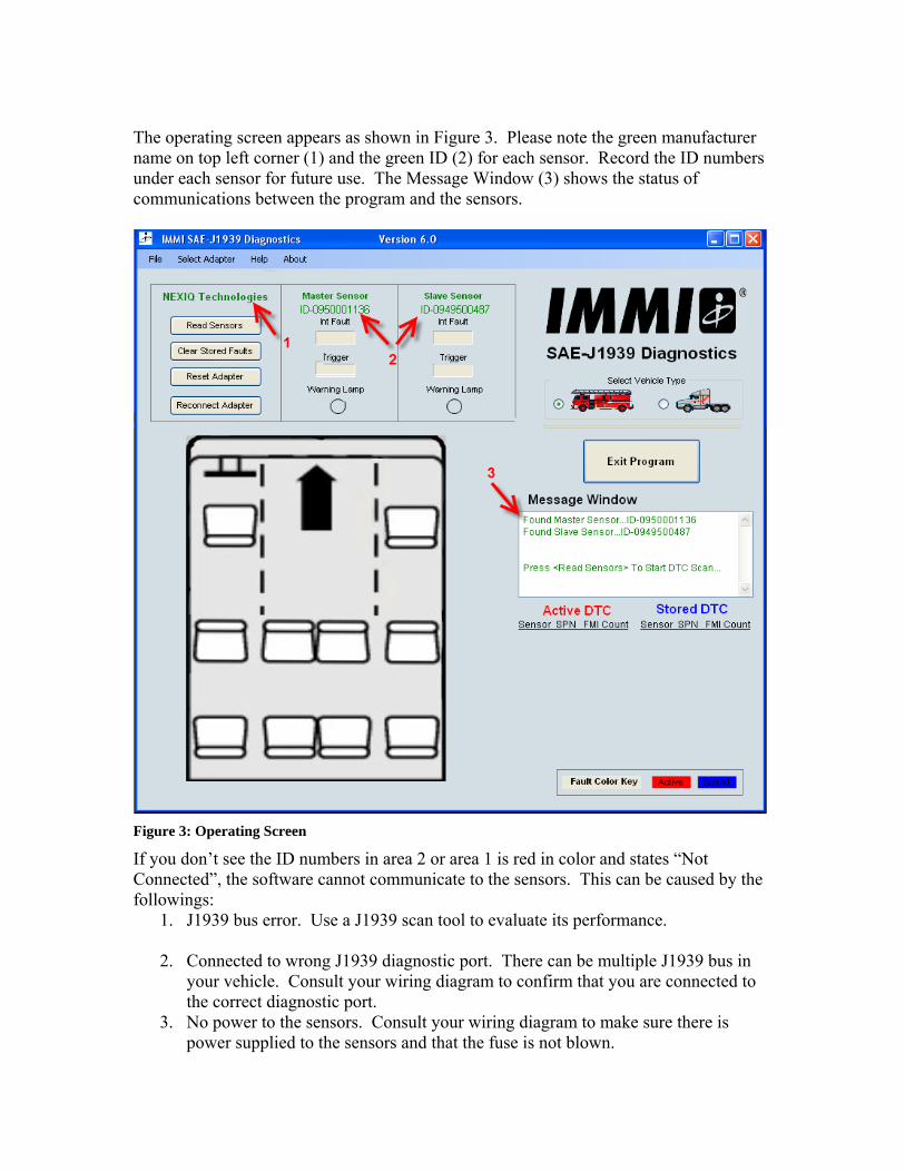
The operating screen appears as shown in Figure 3. Please note the green manufacturer name on top left corner (1) and the green ID (2) for each sensor. Record the ID numbers under each sensor for future use. The Message Window (3) shows the status of communications between the program and the sensors.
Figure 3: Operating Screen
If you don’t see the ID numbers in area 2 or area 1 is red in color and states “Not Connected”, the software cannot communicate to the sensors. This can be caused by the followings:
1. J1939 bus error. Use a J1939 scan tool to evaluate its performance.
2. Connected to wrong J1939 diagnostic port. There can be multiple J1939 bus in your vehicle. Consult your wiring diagram to confirm that you are connected to the correct diagnostic port.
3. No power to the sensors. Consult your wiring diagram to make sure there is power supplied to the sensors and that the fuse is not blown.

4. Adaptor not connected to the computer. Make sure the Adaptor is connected, not
used by other software, and ready to be used by this software. Usually, you can monitor its status using Device Manager.
5. Lack of activity on the J1939 bus. Cycling the power may re-establish bus communications.
Areas 1 and 2 must be green in color and sensor IDs must be recorded before proceeding to the next step. If you experience problems, call technical support after you have verified the following:
1. Proper operation of the adaptor 2. No bus errors 3. Correct diagnostic port
Select the radio button that suits your vehicle type. Selecting different Vehicle Type will cause the pictorial representation of the application to change.
Figure 4: Fire Truck selected Figure 5: Heavy Truck selected
Press the “Read Sensor” button, located at the top left corner, to start communicating with the sensors.
Figure 6: Read Sensor button
The Warning Lamp under each sensor shows status of the fault lamp. If this status is not the same as the physical fault lamp in the vehicle, check the wiring to the fault lamp before proceeding to the next step.

Figure 7: Warning Lamp ON Figure 8: Warning Lamp Off
After retrieving information from the sensor(s), you should see a screen similar to the following diagram (Fig 9) for a fire truck application.
Figure 9: Fire truck with DTCs screen
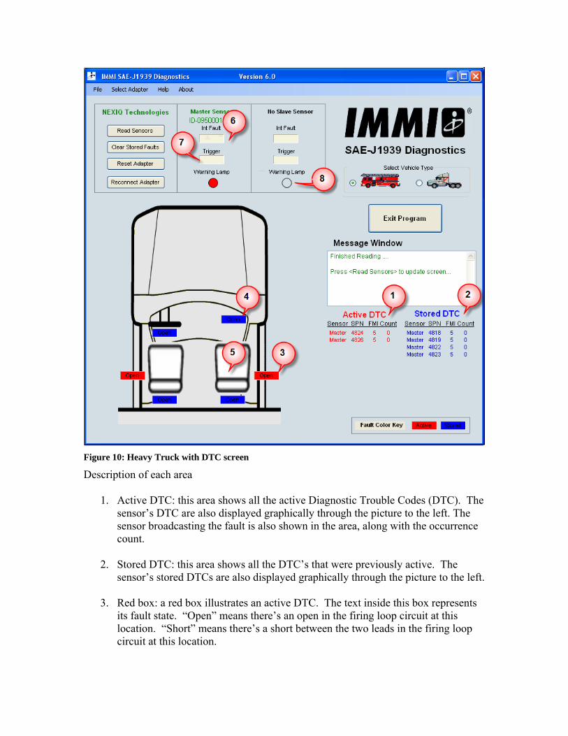
Figure 10: Heavy Truck with DTC screen
Description of each area
1. Active DTC: this area shows all the active Diagnostic Trouble Codes (DTC). The sensor’s DTC are also displayed graphically through the picture to the left. The sensor broadcasting the fault is also shown in the area, along with the occurrence count.
2. Stored DTC: this area shows all the DTC’s that were previously active. The sensor’s stored DTCs are also displayed graphically through the picture to the left.
3. Red box: a red box illustrates an active DTC. The text inside this box represents its fault state. “Open” means there’s an open in the firing loop circuit at this location. “Short” means there’s a short between the two leads in the firing loop circuit at this location.

4. Blue box: a blue box represents a stored DTC. The text inside this box represents its previously active fault state.
5. Seat: this is a graphical representation of the location of each potential firing loop. Note that not all vehicles have all seating locations.
6. Internal Fault: An internal fault can be created when the cab is tilted for servicing, or if there are excessive vibrations at the sensor location.
A slave sensor can generate this fault code if the communication is lost between the Master and Slave. Check the Type II I/O (+/-) wiring circuits between the modules (Pins A12 and A13). Also check the connections to the Master and Slave. After ensuring proper connections, clear the fault(s) by pressing the “Clear Stored Faults” button. If the fault will not clear, the module must be replaced and returned to the manufacturer. UNPLUG roll sensor before attempting to remove from vehicle. Moving an activated roll sensor could deploy safety devices.
7. Trigger: This indicates that a trigger is stored in program memory. Contact IMMI for assistance. Trigger events cannot be cleared with standard diagnostic tools. The roll sensor is designed to activate once. If the system is activated or damaged, authorized technician must replace the unit.
Refer to the vehicle’s RollTek wiring diagram to determine the wiring details. Stored faults may be due to an intermittent wiring issue, so the wiring should be checked before putting the vehicle into service.
∆ WARNING
Before correcting any faults, deactivate the roll sensor by turning off the ignition and battery switch. Do NOT perform service to a live system. Accidental deployment could cause serious injury and property damage.
Identify the source of the open or short circuit. After the wiring is repaired, the fault indicator will change from red to blue. Press “Clear Stored Faults”. Warning light will not deactivate until active and inactive codes are cleared. Verify that vehicle fault lamp matches diagnostic warning lamp status
Note: The connectors going to the pyrotechnic devices and roll sensor are shorted when disconnected. If a digital volt meter is connected to a shorted plug it will not provide an accurate indication of component status.

ELECTRICAL CONNECTIONS The electrical connections to the AB10 sensor are application dependent. Refer to customer drawing for application specific pin assignments. Wiring harness with twisted pairs (≥ 1 turn/in) must be used for device outputs, communication lines, and power supply input. Wire should be 20 AWG, stranded. Use only approved crimped tool and extraction tool when repair of wiring harness is necessary. Follow the instructions as illustrated below when repairing a contact. The following table includes part numbers of the connector mating to the AB10 Master sensor. Location Manufacturer
and Part number
Tool used
Connector A Housing
Tyco 1924685-1 N/A
Connector B Housing
Tyco 1438618-1 N/A
Contacts for A and B
Tyco 1393365-1 Crimp tool : 6-1393462-5 Get B Extraction tool: 3-1579007-6
Table 1: AB10 Master sensor mating connector and contact information
Below instructions on how to extract pins from its connector housing (Information provided by Tyco Electronics)

Figure 11: AB10 Connector A terminal numbers
Figure 12: AB10 Connector B terminal numbers
Figure 13: AB10 Master Sensor Connector A terminal removal instructions

Figure 14: AB10 Master sensor Connector A terminal insertion instructions

Figure 11: AB10 Master sensor connector B terminal removal instructions
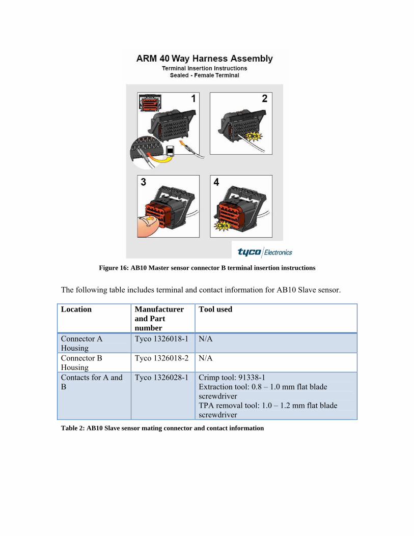
Figure 16: AB10 Master sensor connector B terminal insertion instructions
The following table includes terminal and contact information for AB10 Slave sensor. Location Manufacturer
and Part number
Tool used
Connector A Housing
Tyco 1326018-1 N/A
Connector B Housing
Tyco 1326018-2 N/A
Contacts for A and B
Tyco 1326028-1 Crimp tool: 91338-1 Extraction tool: 0.8 – 1.0 mm flat blade screwdriver TPA removal tool: 1.0 – 1.2 mm flat blade screwdriver
Table 2: AB10 Slave sensor mating connector and contact information
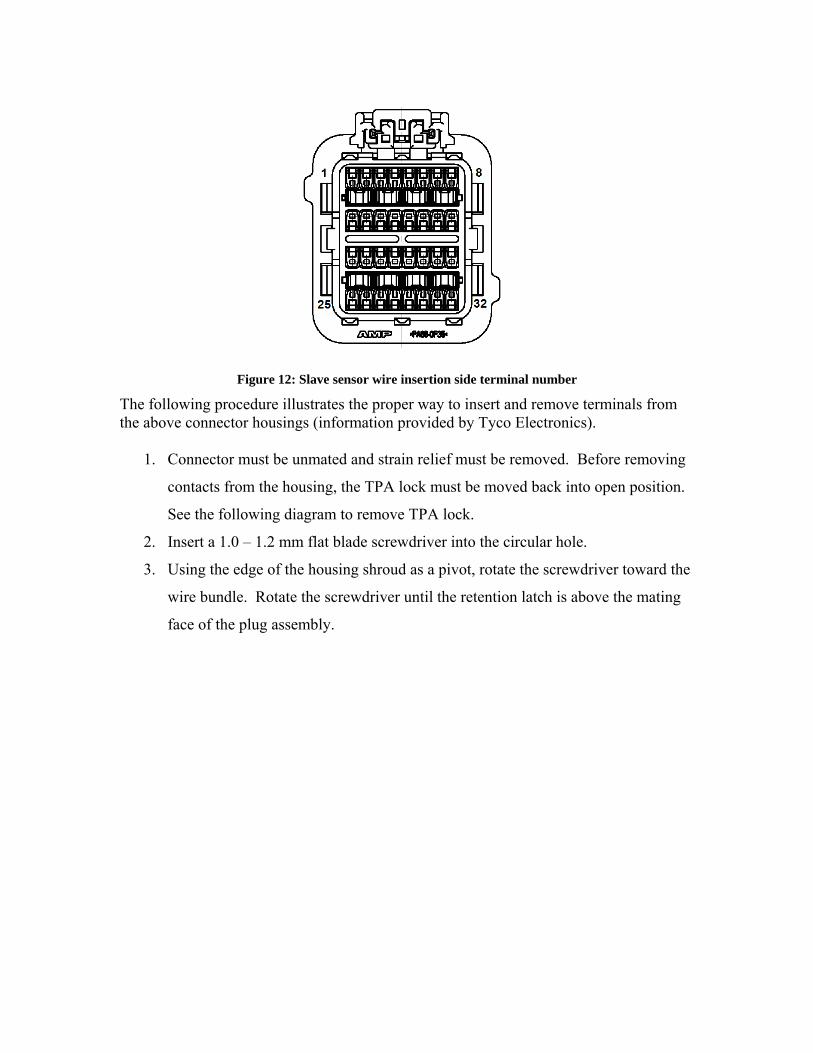
Figure 12: Slave sensor wire insertion side terminal number
The following procedure illustrates the proper way to insert and remove terminals from the above connector housings (information provided by Tyco Electronics).
1. Connector must be unmated and strain relief must be removed. Before removing
contacts from the housing, the TPA lock must be moved back into open position.
See the following diagram to remove TPA lock.
2. Insert a 1.0 – 1.2 mm flat blade screwdriver into the circular hole.
3. Using the edge of the housing shroud as a pivot, rotate the screwdriver toward the
wire bundle. Rotate the screwdriver until the retention latch is above the mating
face of the plug assembly.

Figure 138: AB10 Slave sensor connector TPA removal procedures (from Tyco Electronics)
4. Insert a 0.8 – 1.0 mm flat blade screwdriver into the selected exposed contact
cavity.
5. Hold the wire of the contact to be removed and push the contact forward until it
stops.
6. Using the 0.8 – 1.0 mm flat blade screwdriver, gently deflect the retention finger.
7. Simultaneously pull wire and contact from the plug housing.
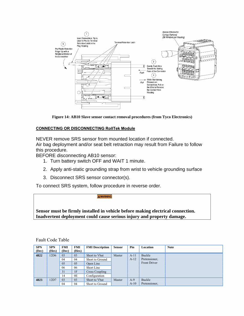
Figure 14: AB10 Slave sensor contact removal procedures (from Tyco Electronics)
CONNECTING OR DISCONNECTING RollTek Module NEVER remove SRS sensor from mounted location if connected. Air bag deployment and/or seat belt retraction may result from Failure to follow this procedure. BEFORE disconnecting AB10 sensor:
1. Turn battery switch OFF and WAIT 1 minute.
2. Apply anti-static grounding strap from wrist to vehicle grounding surface
3. Disconnect SRS sensor connector(s).
To connect SRS system, follow procedure in reverse order.
Sensor must be firmly installed in vehicle before making electrical connection. Inadvertent deployment could cause serious injury and property damage.
Fault Code Table
SPN (Dec)
SPN (Hex)
FMI (Dec)
FMI (Hex)
FMI Description Sensor
Pin Location Note
4822 12D6 03 03 Short to Vbat Master A-11 A-12
Buckle Pretensioner, Front Driver
04 04 Short to Ground 05 05 Open Line 06 06 Short Line 31 1F Cross Coupling 14 0E Configuration
4823 12D7 03 03 Short to Vbat Master A-9 A-10
Buckle Pretensioner,
04 04 Short to Ground

SPN (Dec)
SPN (Hex)
FMI (Dec)
FMI (Hex)
FMI Description Sensor
Pin Location Note
05 05 Open Line Front Passenger 06 06 Short Line 31 1F Cross Coupling 14 0E Configuration
4824 12D8 03 03 Short to Vbat Master B-17 B-18
F1-SRA/IHC 04 04 Short to Ground 05 05 Open Line 06 06 Short Line 31 1F Cross Coupling 14 0E Configuration
4826 12DA 03 03 Short to Vbat Master B-9 B-10
F2-SRA/IHC 04 04 Short to Ground 05 05 Open Line 06 06 Short Line 31 1F Cross Coupling 14 0E Configuration
4828 12DC 03 03 Short to Vbat Master B-19 B-20
Slave #1 This output is available for Master and Slave configuration. In Master only configurations (Frontal Only, Roll Master Only), this output is not available.
04 04 Short to Ground 05 05 Open Line 06 06 Short Line 31 1F Cross Coupling 14 0E Configuration
4834 12E2 03 03 Short to Vbat Slave
B-25 B-26
M1-Buckle Pretensioner
In Master and Slave Configuration.
04 04 Short to Ground
05 05 Open Line Master
B19 B20
In Master Roll Only Configuration 06 06 Short Line 31 1F Cross Coupling 14 0E Configuration
4830 12DE 03 03 Short to Vbat Master B-1 B-2
M1-SRA/IHC 04 04 Short to Ground 05 05 Open Line 06 06 Short Line 31 1F Cross Coupling 14 0E Configuration
4831 12DF 03 03 Short to Vbat Master B-11 B-12
M4-SRA/IHC 04 04 Short to Ground 05 05 Open Line 06 06 Short Line 31 1F Cross Coupling 14 0E Configuration
4832 12E0 03 03 Short to Vbat Master A-7 A-8
Slave 2 This output is available for Master and Slave configuration. In Master only configurations (Frontal Only, Roll Master Only), this output is not available.
04 04 Short to Ground 05 05 Open Line 06 06 Short Line 31 1F Cross Coupling 14 0E Configuration
4835 12E1 03 03 Short to Vbat Slave
B-31 B-32
M4-Buckle Pretensioner
In Master and Slave Configuration.
04 04 Short to Ground 05 05 Open Line
Master A7 A8
In Master Roll Only Configuration
06 06 Short Line 31 1F Cross Coupling 14 0E Configuration
4829 12DD 03 03 Short to Vbat Master B-7 B-8
R1-SRA/IHC 04 04 Short to Ground 05 05 Open Line 06 06 Short Line 31 1F Cross Coupling 14 0E Configuration

SPN (Dec)
SPN (Hex)
FMI (Dec)
FMI (Hex)
FMI Description Sensor
Pin Location Note
4833 12E1 03 03 Short to Vbat Master B-15 B-16
R4-SRA/IHC 04 04 Short to Ground 05 05 Open Line 06 06 Short Line 31 1F Cross Coupling 14 0E Configuration
4836 12E4 05 05 Open Line Slave B-1 B-2
R1 Buckle Pretensioner
06 06 Short Line
4837 12E5 05 05 Open Line Slave B-3 B-4
R2 Buckle Pretensioner
06 06 Short Line
4838 12E6 05 05 Open Line Slave B-5 B-6
R3 Buckle Pretensioner
06 06 Short Line
4839 12E7 05 05 Open Line Slave B-7 B-8
R4 Buckle Pretensioner
06 06 Short Line
4840 12E8 05 05 Open Line Slave B-27 B-28
M2 Buckle Pretensioner
06 06 Short Line
4841 12E9 05 05 Open Line Slave B-29 B-30
M3 Buckle Pretensioner
06 06 Short Line
624 270 03 03 Short to Vbat Master Slave
A-1 A-3
Warning Lamp output Warning Lamp output
Warning Lamp In, to Slave Pin A11 To Warning Lamp Indicator
04 04 Short to Ground 05 05 Open Line 06 06 Short Line 31 1F Cross Coupling 14 0E Configuration
61696 F100 03 03 Vbat Too High Master A-24 A-2
Power Supply Power Supply and Ground 04 04 Vbat too Low
49267 C073 11 0B CAN Busoff Master A19 A-20
CAN-H and CAN-L
4973 136D 14 0E Deployment Fault
Master
36590 8EEE 12 0C Internal fault Master 254 FE 12 0C Internal Fault Slave 240 F0 14 0E Program Memory Slave

Gather info (all info needs to be available before starting troubleshooting procedures):
Manufacturer NameVehicle manufacture yearPart #Name and TitlePhone #Have wiring diagram handy?
Park vehicle in a level stationary
positionTurn ignition Off
RollTek Diagnostic Software Installed
RP1210A device driver installed and
hardware available
Turn Ignition On
N
N
Start RollTek Diagnostic Software
Choose the adaptor you’re
using, then hit OK
Wait…Operating Window appears
Press Read Sensor button
Connect adaptor to Diagnostic port
Locate diagnostic port
Wait…Green Adaptor
Name
Check Adaptor connection
Error window
Contact Adaptor Manufacturer
Resolve issue then restart process
See Green Text above sensor “Connected”
Provide Serial numbers
Red solid Dot under either
sensor?
Check wiring to the diagnostic
lamp
N
N
N
Any Red DTCUnder
message window
Copy Red DTC, under message
window
Reference Table1 for their location
Choose Manual Mode, hit Continue
Choose “Truck” or “Fire”
Pick 1 Red DTCSPN, FMI
Identify FMI
SPN4818481948224823482448254826482848294830483148324833483448354836483748384839
LocationF1-AirbagF2-Airbag
F1-BeltF2-Belt
F1-SRA/IHCN/A
F2-SRA/IHCM2-BeltM1-Belt
M1-SRA/IHCM4-SRA/IHC
M3-BeltM4-Belt
R1-SRA/IHCR4-SRA/IHC
R1-BeltR2-BeltR3-BeltR4-Belt
Fire
LocationDriver-AirbagPass-AirbagDriver-BeltPass-Belt
Driver-SideAirN/A
Pass-SideAirSIL1SIL2SIL3SIL4SIL5SIL6SIL7SIL8SIL9
SIL10SIL11SIL12
Truck
Table 1: SPN to Location
FMI = 5Open
FMI = 6Short
Turn offIgnition and
Battery switch before attempting
any repair
Find location of the wires identified
above
Firing loop exists?
Consult wiring diagram
Check 2.2 ohm resistor connection
Check connection to Ignitor
N
N
SPN in Table 1
Fix problem
The DTC disappeared
Press Clear Stored Faults
Press Read Sensors
N
More Red DTC?
Press Read Sensors Button
Any Blue Stored DTC?
Forward call to Engineering
Problem Solved
N
N
Any Blue DTC under message
window?
N
Forward call to Engineering
Problem Solved
Press Clear Stored Faults
Press Read Sensors Button
Any Blue Stored DTC?
N
N
Check connection
several times already?
N
Purpose:1. Gather General Information about the problematic vehicle and personel2. Help solve routine problems without Engineering assistance

![DCU 305 R3 CAN / J1939 Manual - Auto-Maskin§ [a] SAE, J1939-71 § [b] SAE, J1939-73 § [c] Conrad Etschberger, “Controller Area Network” ... CAN / J1939 Manual CAN / J1939 –](https://img.pdfslide.us/doc/110x75/5ae535d97f8b9a7b218f6863/dcu-305-r3-can-j1939-manual-auto-maskin-a-sae-j1939-71-b-sae-j1939-73.jpg)