Embed Size (px)
Citation preview
INTRODUCTIONVehicles are surely vital part of our lives, but they are also
major sources of environmental issues. To improve thevehicle emission quality, researchers of various fields haveattempted to develop more efficient engines, hybridization,weight reduction, etc. Among these, one of the technologiesthat can bring the most prominent improvement in vehicleenergy efficiency and thus emission relates to powertransmission.
Two of the most widely accepted transmission types areautomatic transmission with a torque converter andtraditional manual transmission. Both types involve distinctstrengths and weaknesses.
The manual transmission has the advantage of lightweight and high energy transmission efficiency. The powersource and the wheels are mechanically linked through theclutch disks. However, it has the disadvantage of
inconvenience coming from having to frequently maneuverthe clutch pedal and gear selectors as the driver drives thevehicle.
On the other hand, the automatic transmission is knownfor its smooth gear shifting and convenience. Through the useof torque converter, it can operate without having to operatethe clutch. However, such use of torque converter inducesenergy loss, since slipping is allowed in the driveline (despitethe previous works to effectively control the lock-up clutch[1, 2, 3, 4]). Also, the unit cost is relatively higher than that oftraditional manual transmission.
Such trade-offs that exist in the two transmission typesinspired the researchers to develop a novel type oftransmission called automated manual transmission (AMT)which can provide both energy efficiency and convenience[5, 6, 7]. Here, the clutch actuator and gear shiftingmechanisms actuate the gear shifts to form an automatedsystem.
2013-01-2587Published 10/14/2013
Copyright © 2013 SAE International and Copyright © 2013 KSAEdoi:10.4271/2013-01-2587saepcmech.saejournals.org
Robust Feedback Tracking Controller Design for Self-Energizing Clutch Actuator of Automated Manual
TransmissionJiwon Oh
KAIST
Jinsung KimHyundai Motors
Seibum ChoiKAIST
ABSTRACTThis study mainly focuses on developing an accurate tracking controller for the self-energizing clutch actuator (SECA)
system consisting of a DC motor with an encoder applied on the automated manual transmission (AMT). In the position-based actuation of the SECA, abruptly increasing torque near the clutch kissing point during the clutch engagementprocess induces control input saturation and jerky response when a conventional feedback controller is applied. Theproposed work resolves such issue and significantly increases the control accuracy of the actuator through the developmentof an effective H-infinity controller. The control performance is shown to be more effective than a simple PID controllervia simulation and experiments using an AMT test bench equipped with SECA aided by d-SPACE and Matlab/Simulink.
CITATION: Oh, J., Kim, J., and Choi, S., "Robust Feedback Tracking Controller Design for Self-Energizing ClutchActuator of Automated Manual Transmission," SAE Int. J. Passeng. Cars - Mech. Syst. 6(3):2013, doi:10.4271/2013-01-2587.
____________________________________
1510
Compared to the conventional AMT system, the AMTequipped with SECA [8, 9] uses smaller-size actuator. This isbecause, in the conventional system, the actuator alone mustovercome the normal force great enough to prevent themission from slipping when high amount of torque is appliedto the driveline, whereas in the AMT with SECA, the self-energizing mechanism of the clutch hardware assists themotor when positive torque is applied. As a result, SECAenables cost and weight reduction and improves actuationefficiency, but involves higher sensitivity to actuator stroke.
Thus, to ensure robust actuator control performance,accurate actuation even under the influence of uncertainties iscrucial, and it cannot be achieved with conventional PIDcontrol. The proposed study finds its resolution in h-infinitycontrol method. This paper is structured as follows. Section Iintroduces the hardware and modeling of the AMT systemequipped with SECA. Section II deals with formation of thetest bench and how the empirical model used for h-infinitycontroller synthesis is induced. Section III shows the loopshaping process for h-infinity controller synthesis andanalysis. Section IV displays the simulation/experimentalresults obtained by applying the suggested controller onto thetest bench with SECA, and compares it with the resultobtained by using the conventional PID control.
AUTOMATED MANUALTRANSMISSION WITH SELF-
ENERGIZING CLUTCH ACTUATOROne of the major weaknesses of the conventional
AMT/DCT is in the actuator. To ensure sufficient normalforce between the clutch disks for engagement even duringhigh amount of torque flow, stiff diaphragm or coil springsare used. The proper actuation of the clutch system with suchnature demands a high-power motor, which increases therequired amount of control effort and weight. Here, the self-energizing clutch actuator system can be effective ineliminating such issues. SECA replaces the diaphragm springof the conventional system, by designing the hardware inwhich the torque flow can work in a favorable way toincrease the normal force in the clutch. In other words, torqueapplied onto the clutch induces the self-energizing clutch diskto telescope toward the direction of increasing normal force,so that the clutch disks can be engaged even with a smallamount of actuation force. Such mechanism allows theamount of required actuation energy to be significantlyreduced, which can lead to the optimization of thetransmission both in its efficiency and weight, and at thesame time securing the dramatic fuel efficiency improvement.
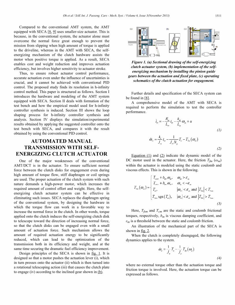
Design principles of the SECA is shown in fig. 1. It isdesigned so that a motor pushes the actuation lever (i), whichin turn presses onto the actuator (ii) which is then turned intoa rotational telescoping action (iii) that causes the clutch plateto engage (iv) according to the inclined gear shown in (b).
Figure 1. (a) Sectional drawing of the self-energizingclutch actuator system, (b) implementation of the self-energizing mechanism by installing the pinion guide
gears between the actuation and fixed plate, (c) operatingschematics of the clutch actuation for engagement.
Further details and specification of the SECA system canbe found in [8].
A comprehensive model of the AMT with SECA isrequired to perform the simulation to test the controllerperformance.
(1)
(2)
Equation (1) and (2) indicate the dynamic model of theDC motor used in the actuator. Here, the friction Tfm (ωm)within the actuator is modeled using the static coulomb andviscous effects. This is shown in the following.
(3)
Here, Tfsm and Tcm are the static and coulomb frictionaltorques, respectively, bm is viscous damping coefficient, andεm is a threshold between the static and coulomb friction.
An illustration of the mechanical part of the SECA isshown in fig. 2.
When the clutch is completely disengaged, the followingdynamics applies to the system.
(4)
where no external torque other than the actuation torque andfriction torque is involved. Here, the actuation torque can beexpressed as follows.
Oh et al / SAE Int. J. Passeng. Cars - Mech. Syst. / Volume 6, Issue 3(November 2013) 1511
(5)
Where ig and ka are the gear ratio of motor to theactuation lever, and the equivalent actuation lever stiffness,respectively. Also, similar to how the motor friction ismodeled, the actuator friction is modeled as the following.
(6)
Again, the terms are named analogously to those of themotor friction.
Now, as the clutch begins to engage, another term must beincluded to express the transmitted clutch torque.
(7)
The added terms Tc and Ts each represent the clutchfriction torque and the self-energizing torque. Apart from thefriction torque as a loss, the clutch friction torque is thetorque that is actually transmitted to the engaged clutch. Theself-energizing torque arises from the structural design of theSECA which works in the direction of locking the clutchestogether. Both are functions of the clutch normal force, andthus they can be expressed as follows.
(8)
where Rc is the effective clutch radius, and
(9)
Here, since the clutch normal force and the self-energizing reaction force can be expressed as
(10)
(11)
equation (7) can be rewritten as the following.
(12)
Notice how β can simply be zero to reach (4) in case theclutch is disengaged.
Figure 2. Illustration of the self-energizing clutchactuator mechanism
TEST BENCH FREQUENCYANALYSIS
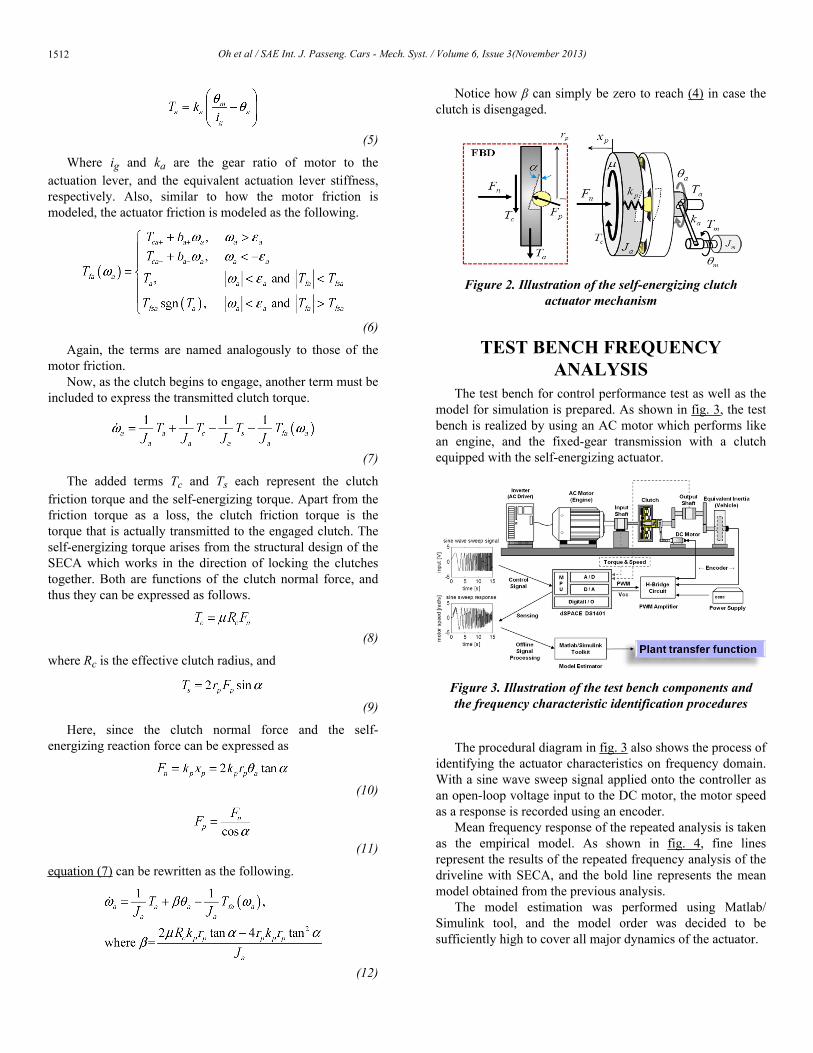
The test bench for control performance test as well as themodel for simulation is prepared. As shown in fig. 3, the testbench is realized by using an AC motor which performs likean engine, and the fixed-gear transmission with a clutchequipped with the self-energizing actuator.
Figure 3. Illustration of the test bench components andthe frequency characteristic identification procedures
The procedural diagram in fig. 3 also shows the process ofidentifying the actuator characteristics on frequency domain.With a sine wave sweep signal applied onto the controller asan open-loop voltage input to the DC motor, the motor speedas a response is recorded using an encoder.
Mean frequency response of the repeated analysis is takenas the empirical model. As shown in fig. 4, fine linesrepresent the results of the repeated frequency analysis of thedriveline with SECA, and the bold line represents the meanmodel obtained from the previous analysis.
The model estimation was performed using Matlab/Simulink tool, and the model order was decided to besufficiently high to cover all major dynamics of the actuator.
Oh et al / SAE Int. J. Passeng. Cars - Mech. Syst. / Volume 6, Issue 3(November 2013)1512
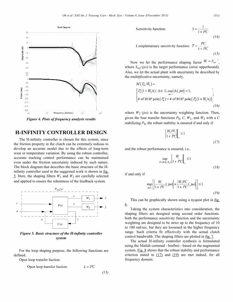
Figure 4. Plots of frequency analysis results
H-INFINITY CONTROLLER DESIGNThe H-infinity controller is chosen for this system, since
the friction property in the clutch can be extremely tedious todevelop an accurate model due to the effects of long-termwear or temperature variation. By using the robust controller,accurate tracking control performance can be maintainedeven under the friction uncertainty induced by such nature.The block diagram that describes the basic structure of the H-infinity controller used in the suggested work is shown in fig.5. Here, the shaping filters W1 and W2 are carefully selectedand applied to ensure the robustness of the feedback system.
Figure 5. Basic structure of the H-infinity controllersystem
For the loop shaping purpose, the following functions aredefined.
Open loop transfer fuction:
(13)
(14)
(15)
Now we let the performance shaping factor ,where Sref (jω) is the target performance (error upperbound).Also, we let the actual plant with uncertainty be described bythe multiplicative uncertainty, namely,
(16)
where W2 (jω) is the uncertainty weighting function. Then,given the four transfer functions P0, C, W1, and W2 with a Cstabilizing P0, the robust stability is ensured if and only if
(17)
and the robust performance is ensured, i.e.,
(18)
if and only if
(19)
This can be graphically shown using a nyquist plot in fig.6.
Taking the system characteristics into consideration, theshaping filters are designed using second order functions.both the performance sensitivity function and the uncertaintyweighting are designed to be strict up to the frequency of 10to 100 rad/sec, but they are loosened in the higher frequencyrange. Such criteria fit effectively with the actual clutchcontrol bandwidth. The shaping filters are plotted in fig. 7.
The actual H-infinity controller synthesis is formulatedusing the Matlab commad - hinflmi - based on the augmentedsystem. Fig. 8 shows that the robust stability and performancecriterion stated in (17) and (19) are met indeed, for allfrequency domain.
Oh et al / SAE Int. J. Passeng. Cars - Mech. Syst. / Volume 6, Issue 3(November 2013) 1513
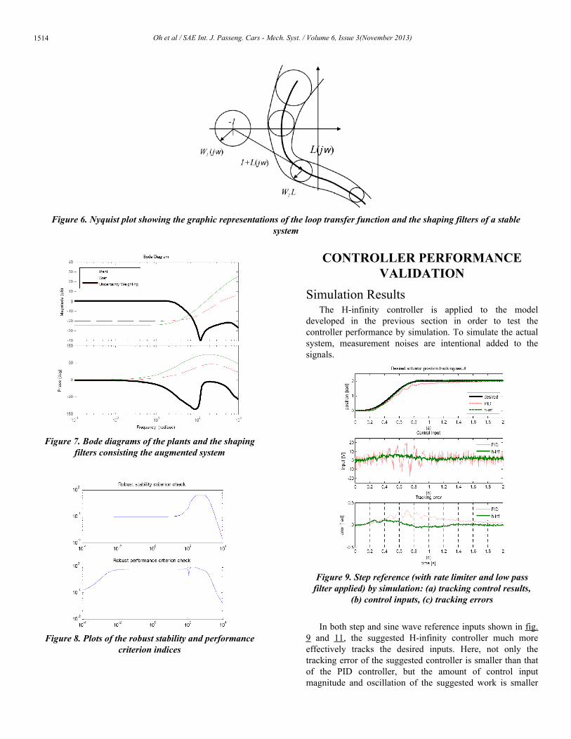
Figure 7. Bode diagrams of the plants and the shapingfilters consisting the augmented system
Figure 8. Plots of the robust stability and performancecriterion indices
CONTROLLER PERFORMANCEVALIDATION
Simulation ResultsThe H-infinity controller is applied to the model
developed in the previous section in order to test thecontroller performance by simulation. To simulate the actualsystem, measurement noises are intentional added to thesignals.
Figure 9. Step reference (with rate limiter and low passfilter applied) by simulation: (a) tracking control results,
(b) control inputs, (c) tracking errors
In both step and sine wave reference inputs shown in fig.9 and 11, the suggested H-infinity controller much moreeffectively tracks the desired inputs. Here, not only thetracking error of the suggested controller is smaller than thatof the PID controller, but the amount of control inputmagnitude and oscillation of the suggested work is smaller
Figure 6. Nyquist plot showing the graphic representations of the loop transfer function and the shaping filters of a stablesystem
Oh et al / SAE Int. J. Passeng. Cars - Mech. Syst. / Volume 6, Issue 3(November 2013)1514
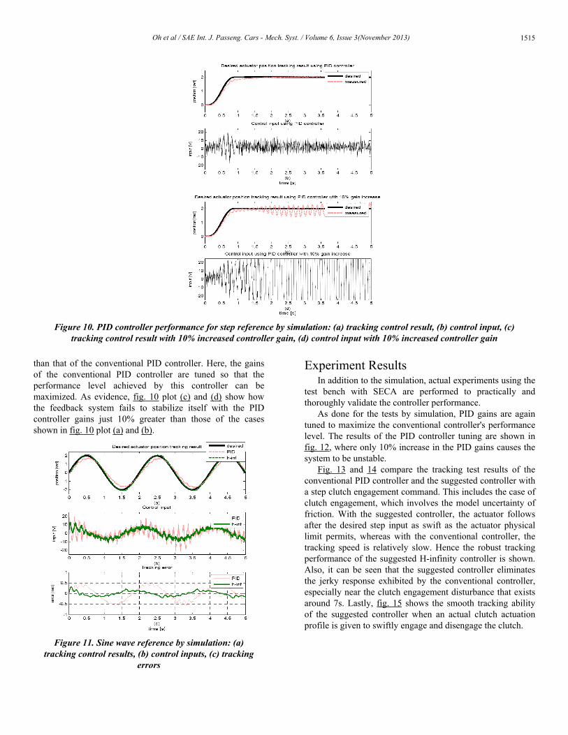
than that of the conventional PID controller. Here, the gainsof the conventional PID controller are tuned so that theperformance level achieved by this controller can bemaximized. As evidence, fig. 10 plot (c) and (d) show howthe feedback system fails to stabilize itself with the PIDcontroller gains just 10% greater than those of the casesshown in fig. 10 plot (a) and (b).
Figure 11. Sine wave reference by simulation: (a)tracking control results, (b) control inputs, (c) tracking
errors
Experiment ResultsIn addition to the simulation, actual experiments using the
test bench with SECA are performed to practically andthoroughly validate the controller performance.
As done for the tests by simulation, PID gains are againtuned to maximize the conventional controller's performancelevel. The results of the PID controller tuning are shown infig. 12, where only 10% increase in the PID gains causes thesystem to be unstable.
Fig. 13 and 14 compare the tracking test results of theconventional PID controller and the suggested controller witha step clutch engagement command. This includes the case ofclutch engagement, which involves the model uncertainty offriction. With the suggested controller, the actuator followsafter the desired step input as swift as the actuator physicallimit permits, whereas with the conventional controller, thetracking speed is relatively slow. Hence the robust trackingperformance of the suggested H-infinity controller is shown.Also, it can be seen that the suggested controller eliminatesthe jerky response exhibited by the conventional controller,especially near the clutch engagement disturbance that existsaround 7s. Lastly, fig. 15 shows the smooth tracking abilityof the suggested controller when an actual clutch actuationprofile is given to swiftly engage and disengage the clutch.
Figure 10. PID controller performance for step reference by simulation: (a) tracking control result, (b) control input, (c)tracking control result with 10% increased controller gain, (d) control input with 10% increased controller gain
Oh et al / SAE Int. J. Passeng. Cars - Mech. Syst. / Volume 6, Issue 3(November 2013) 1515
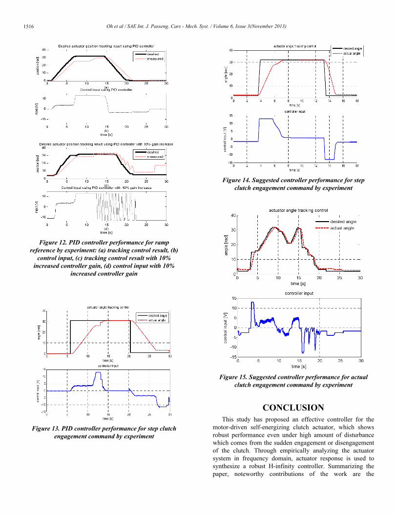
Figure 12. PID controller performance for rampreference by experiment: (a) tracking control result, (b)
control input, (c) tracking control result with 10%increased controller gain, (d) control input with 10%
increased controller gain
Figure 13. PID controller performance for step clutchengagement command by experiment
Figure 14. Suggested controller performance for stepclutch engagement command by experiment
Figure 15. Suggested controller performance for actualclutch engagement command by experiment
CONCLUSIONThis study has proposed an effective controller for the
motor-driven self-energizing clutch actuator, which showsrobust performance even under high amount of disturbancewhich comes from the sudden engagement or disengagementof the clutch. Through empirically analyzing the actuatorsystem in frequency domain, actuator response is used tosynthesize a robust H-infinity controller. Summarizing thepaper, noteworthy contributions of the work are the
Oh et al / SAE Int. J. Passeng. Cars - Mech. Syst. / Volume 6, Issue 3(November 2013)1516
following: improvement of the actuator tracking controlaccuracy in general, reduction of the amount of controlvoltage fluctuation, effective rejection of the suddendisturbance, and reduction of the jerky response of the clutchactuator. The proposed controller has been verified to beeffective both through simulation using the modeleddriveline, and experiments using an actual test bench withSECA.
REFERENCES1. Hibino, R., Osawa M., Kono K., and Yoshizawa K.. “Robust and
simplified design of slip control system for torque converter lock-upclutch.” Journal of dynamic systems, measurement, and control 131(1),2009.
2. Hirata, Mitsuo, IIno Fumiyo, IIno Fumiyo, Kaneko Yutaka, and AdachiKazutaka. “Performance Enhancement of Slip Control of a Lock-UpClutch by Using Gain-Scheduled H infinity Control Method.” IEEJTransactions on Industry Applications 130(10): 1139-1146, 2010.
3. Nianjiong, Yang, Lijun Qian, and Daojun Wu. “Lock-up controlsimulation of torque converter with lock-up clutch.” 2010 2ndInternational Conference on Future Computer and Communication(ICFCC), vol. 1, pp. V1-290, 2010.
4. Gao, Bingzhao, Chen Hong, Liu Qifang, and Sanada Kazushi. “Clutchslip control of automatic transmissions: A nonlinear feedforward-feedback design.” 2010 IEEE International Conference on ControlApplications (CCA), 884-889, 2010.
5. Glielmo, Luigi, Iannelli Luigi, Vacca Vladimiro, and Vasca Francesco.“Gearshift control for automated manual transmissions.” Transactionson Mechatronics, IEEE/ASME 11(1): 17-26, 2006.
6. Hwang, S. “Development of automatic clutch actuator for automatedmanual transmissions.” International journal of automotive technology,6(5): 461-466, 2005.
7. Horn, Joachim, Bamberger Joachim, Michau Peter, and Pindl Stephan.“Flatness-based clutch control for automated manual transmissions.”Control Engineering Practice, 11(12): 1353-1359, 2003.
8. Kim, Jinsung, and Choi Seibum B.. “Self-energizing clutch actuatorsystem: Basic concept and design.” Proc. FISITA 2010 WorldAutomotive Congress, (2010.
9. Kim, Jinsung, and Choi Seibum B.. “Design and modeling of a clutchactuator system with self-energizing mechanism.” IEEE/ASMETransactions on Mechatronics, 16(5): 953-966, 2011.
ACKNOWLEDGMENTSThis work was supported by the National Research
Foundation of Korea (NRF) grant funded by the Koreagovernment (MSIP) (No. 2010-0028680), Global Ph. D.Fellowship Program (NRF-2012H1A2A1048938), andCITRC(Convergence Information Technology ResearchCenter) support program (NIPA-2013-H0401-13-1008)supervised by the NIPA(National IT Industry PromotionAgency).
Oh et al / SAE Int. J. Passeng. Cars - Mech. Syst. / Volume 6, Issue 3(November 2013) 1517