Embed Size (px)
Citation preview

ROBOTICS
Application manualMultiMove

Trace back information:Workspace R18-2 version a11Checked in 2018-10-11Skribenta version 5.3.008
Application manualMultiMove
RobotWare 6.08
Document ID: 3HAC050961-001Revision: E
© Copyright 2004-2018 ABB. All rights reserved.Specifications subject to change without notice.
The information in this manual is subject to change without notice and should notbe construed as a commitment by ABB. ABB assumes no responsibility for any errorsthat may appear in this manual.Except as may be expressly stated anywhere in this manual, nothing herein shall beconstrued as any kind of guarantee or warranty by ABB for losses, damages topersons or property, fitness for a specific purpose or the like.In no event shall ABB be liable for incidental or consequential damages arising fromuse of this manual and products described herein.This manual and parts thereof must not be reproduced or copied without ABB'swritten permission.Keep for future reference.Additional copies of this manual may be obtained from ABB.
Original instructions.
© Copyright 2004-2018 ABB. All rights reserved.Specifications subject to change without notice.
ABB AB, RoboticsRobotics and MotionSe-721 68 Västerås
Sweden
Table of contents7Overview of this manual ...................................................................................................................9Product documentation ....................................................................................................................
11Safety ................................................................................................................................................
131 Introduction131.1 About MultiMove ...............................................................................................141.2 Terminology .....................................................................................................151.3 Example applications .........................................................................................151.3.1 About the example applications .................................................................161.3.2 Example "UnsyncArc" ..............................................................................171.3.3 Example "SyncArc" .................................................................................
192 Installation192.1 Hardware installation .........................................................................................192.1.1 About the hardware installation ..................................................................202.1.2 Connections on the control module ............................................................252.1.3 Connections on the drive module ...............................................................272.2 Software installation ..........................................................................................272.2.1 Software installation ................................................................................
293 Configuration293.1 Configuration overview .......................................................................................303.2 System parameters ...........................................................................................303.2.1 Controller topic ......................................................................................323.2.2 Motion topic ...........................................................................................343.2.3 I/O topic ................................................................................................353.3 Configuration examples ......................................................................................353.3.1 Configuration example for "UnsyncArc" .......................................................373.3.2 Configuration example for "SyncArc" ..........................................................393.3.3 I/O configuration example .........................................................................
414 Calibration414.1 Calibration overview ..........................................................................................424.2 Relative calibration ............................................................................................444.3 Calibration chains .............................................................................................454.4 Examples of coordinate systems ..........................................................................454.4.1 Example "UnsyncArc" ..............................................................................464.4.2 Example "SyncArc" .................................................................................
475 User interface specific for MultiMove475.1 FlexPendant for MultiMove system .......................................................................485.2 Status bar indications ........................................................................................505.3 Opening the Program Editor ................................................................................515.4 Production Window ...........................................................................................525.5 Mechanical unit menu ........................................................................................535.6 Select which tasks to start with START button ........................................................
556 Programming556.1 RAPID components ...........................................................................................586.2 Tasks and programming techniques .....................................................................596.3 Coordinated work objects ...................................................................................606.4 Independent movements ....................................................................................606.4.1 About independent movements .................................................................616.4.2 Example "UnsyncArc" with independent movements .....................................
Application manual - MultiMove 53HAC050961-001 Revision: E
© Copyright 2004-2018 ABB. All rights reserved.
Table of contents
636.5 Semi coordinated movements .............................................................................636.5.1 About semi coordinated movements ...........................................................646.5.2 Example "SyncArc" with semi coordinated movements ..................................696.5.3 Considerations and limitations when using semi coordinated movements ..........716.6 Coordinated synchronized movements ..................................................................716.6.1 About coordinated synchronized movements ...............................................726.6.2 Example "SyncArc" with coordinated synchronized movement ........................756.7 Program execution ............................................................................................756.7.1 Corner zones ..........................................................................................776.7.2 Synchronization behavior .........................................................................786.7.3 Dummy instructions .................................................................................796.7.4 Motion principles .....................................................................................806.7.5 Modify position .......................................................................................816.7.6 Moving a program pointer .........................................................................826.7.7 Tool orientation at circular movements ........................................................836.7.8 Applications affected by MultiMove .............................................................846.8 Programming recommendations ..........................................................................846.8.1 Programming recommendations ................................................................
877 RAPID error recovery877.1 Error recovery for MultiMove ...............................................................................887.2 Simple error recovery example ............................................................................897.3 Asynchronously raised errors .............................................................................917.4 Example of creating asynchronously raised error ....................................................937.5 Example with movements in error handler .............................................................
958 Running a subset of a MultiMove system958.1 How to continue with one or more drive units inactive. .............................................988.2 Running a subset in the “Unsync Arc” examples .....................................................
101Index
6 Application manual - MultiMove3HAC050961-001 Revision: E
© Copyright 2004-2018 ABB. All rights reserved.
Table of contents
Overview of this manualAbout this manual
This manual contains information about the RobotWare optionsMultiMoveIndependent and MultiMove Coordinated. The latter includes some extendedfunctionality. Unless something else is specified, MultiMove refers to both theseoptions.
UsageThis manual can be used either as a brief description to find out if MultiMove isthe right choice for solving a problem, or as a description of how to use it. Thismanual provides information about system parameters and RAPID componentsrelated to MultiMove, and many examples of how to use them. The details regardingsyntax for RAPID components, and similar, are not described here, but can befound in the respective reference manual.
Who should read this manual?This manual is mainly intended for robot programmers.
PrerequisitesThe reader should...
• be familiar with industrial robots and their terminology.• be familiar with the RAPID programming language.• be familiar with system parameters and how to configure them.• be familiar with the option Multitasking (seeApplicationmanual - Engineering
tools).
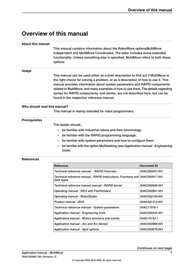
References
Document IDReference
3HAC050947-001Technical reference manual - RAPID Overview
3HAC050917-001Technical reference manual - RAPID Instructions, Functions andData types
3HAC050946-001Technical reference manual manual - RAPID kernel
3HAC050941-001Operating manual - IRC5 with FlexPendant
3HAC032104-001Operating manual - RobotStudio
3HAC021313-001Product manual - IRC5
3HAC17076-1Technical reference manual - System parameters
3HAC020434-001Application manual - Engineering tools
3HAC18152-1Application manual - Motion functions and events
3HAC050988-001Application manual - Arc and Arc Sensor
3HAC050979-001Application manual - Spot options
Continues on next pageApplication manual - MultiMove 73HAC050961-001 Revision: E
© Copyright 2004-2018 ABB. All rights reserved.
Overview of this manual
Revisions
DescriptionRevision
Released with RobotWare 6.0.-
Released with RobotWare 6.01.• Added information about the Ethernet switch, see Ethernet connections
on page 21.
A
Released with RobotWare 6.02.BSection Create a MultiMove system on page 27 updated to use InstallationManager.
Released with RobotWare 6.04.• Minor corrections.
C
Released with RobotWare 6.05.• Minor corrections.
D
Released with RobotWare 6.08.• Max number of motion tasks changed to seven.
E
8 Application manual - MultiMove3HAC050961-001 Revision: E
© Copyright 2004-2018 ABB. All rights reserved.
Overview of this manualContinued
Product documentationCategories for user documentation from ABB Robotics
The user documentation from ABB Robotics is divided into a number of categories.This listing is based on the type of information in the documents, regardless ofwhether the products are standard or optional.All documents can be found via myABB Business Portal, www.myportal.abb.com.
Product manualsManipulators, controllers, DressPack/SpotPack, and most other hardware isdelivered with a Product manual that generally contains:
• Safety information.• Installation and commissioning (descriptions of mechanical installation or
electrical connections).• Maintenance (descriptions of all required preventive maintenance procedures
including intervals and expected life time of parts).• Repair (descriptions of all recommended repair procedures including spare
parts).• Calibration.• Decommissioning.• Reference information (safety standards, unit conversions, screw joints, lists
of tools).• Spare parts list with corresponding figures (or references to separate spare
parts lists).• References to circuit diagrams.
Technical reference manualsThe technical reference manuals describe reference information for roboticsproducts, for example lubrication, the RAPID language, and system parameters.
Application manualsSpecific applications (for example software or hardware options) are described inApplication manuals. An application manual can describe one or severalapplications.An application manual generally contains information about:
• The purpose of the application (what it does and when it is useful).• What is included (for example cables, I/O boards, RAPID instructions, system
parameters, software).• How to install included or required hardware.• How to use the application.• Examples of how to use the application.
Continues on next pageApplication manual - MultiMove 93HAC050961-001 Revision: E
© Copyright 2004-2018 ABB. All rights reserved.
Product documentation
Operating manualsThe operating manuals describe hands-on handling of the products. The manualsare aimed at those having first-hand operational contact with the product, that isproduction cell operators, programmers, and troubleshooters.
10 Application manual - MultiMove3HAC050961-001 Revision: E
© Copyright 2004-2018 ABB. All rights reserved.
Product documentationContinued
SafetySafety of personnel
A robot is heavy and extremely powerful regardless of its speed. A pause or longstop in movement can be followed by a fast hazardous movement. Even if a patternof movement is predicted, a change in operation can be triggered by an externalsignal resulting in an unexpected movement.Therefore, it is important that all safety regulations are followed when enteringsafeguarded space.
Safety regulationsBefore beginning work with the robot, make sure you are familiar with the safetyregulations described in the manualOperatingmanual - General safety information.
Application manual - MultiMove 113HAC050961-001 Revision: E
© Copyright 2004-2018 ABB. All rights reserved.
Safety

This page is intentionally left blank
1 Introduction1.1 About MultiMove
PurposeThe purpose of MultiMove is to let one controller handle several robots. This doesnot only save on hardware costs, it also allows advanced coordination betweendifferent robots and other mechanical units.Here are some examples of applications:
• Several robots can work on the same moving work object.• One robot can move a work object while other robots work on it.• Several robots can cooperate to lift heavy objects.
Included functionalityMultiMove allows up to 7 tasks to be motion tasks (task that has move instructions).Since no more than 4 drive modules can be used, a controller can handle up to 4robots. However, additional axes can be handled by separate tasks up to a totalof 7 motion tasks.Both MultiMove options allow you to implement:
• Independent movements (see Independent movements on page 60)• Semi coordinated movements (seeSemi coordinatedmovements on page63)
In addition to what is mentioned above, the option MultiMove Coordinated allowsyou to implement:
• Coordinated synchronized movements (see Coordinated synchronizedmovements on page 71)
Included optionsIf you have MultiMove, you automatically have access to some options that arenecessary in order to use MultiMove.MultiMove always includes the option:
• MultitaskingIn addition to what is mentioned above, MultiMove Coordinated includes the option:
• Multiple Axis Positioner
Basic approachThis is the general approach for setting up a MultiMove system.
1 Install hardware and software (see Installation on page 19).2 Configure system parameters (see Configuration on page 29).3 Calibrate coordinate systems (see Calibration on page 41).4 Write RAPID program for each task (see Programming on page 55).
Application manual - MultiMove 133HAC050961-001 Revision: E
© Copyright 2004-2018 ABB. All rights reserved.
1 Introduction1.1 About MultiMove
1.2 Terminology
About these termsSome words have a specific meaning when used in this manual. It is important tounderstand exactly what is meant by these words. This manual's definition of thesewords are listed below.
Term list
ExplanationTerm
A robot that is coordinated to a work object will follow themovements of that work object.
Coordination
Movements that are simultaneous. Synchronization refersto a similarity in time, not in room coordinates.
Synchronization
A mechanical unit without TCP, which can only handle jointmovements. A positioner is a mechanical unit, with one orseveral axes, that holds and moves a work object.
Positioner
A mechanical unit with TCP, which can be programmed inCartesian coordinates (x, y and z).
Robot
The same as a program. It is just a way of specifying that itis a program for one specific task.
Task program
14 Application manual - MultiMove3HAC050961-001 Revision: E
© Copyright 2004-2018 ABB. All rights reserved.
1 Introduction1.2 Terminology
1.3 Example applications
1.3.1 About the example applications
Three consistent examplesIn this manual there are many examples (for configuration, RAPID code etc.). Everyexample is created for one of three physical robot systems. These example robotsystem setups are called "UnsyncArc", "SyncArc" and "SyncSpot" and will helpyou understand what kind of robot system an example is made for. The examplesare also consistent, i.e. the RAPID code example for "SyncSpot" is made for arobot system configured as the configuration example for "SyncSpot".
Application manual - MultiMove 153HAC050961-001 Revision: E
© Copyright 2004-2018 ABB. All rights reserved.
1 Introduction1.3.1 About the example applications
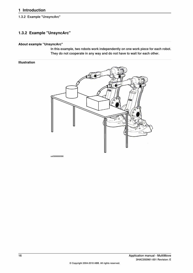
1.3.2 Example "UnsyncArc"
About example "UnsyncArc"In this example, two robots work independently on one work piece for each robot.They do not cooperate in any way and do not have to wait for each other.
Illustration
xx0300000590
16 Application manual - MultiMove3HAC050961-001 Revision: E
© Copyright 2004-2018 ABB. All rights reserved.
1 Introduction1.3.2 Example "UnsyncArc"
1.3.3 Example "SyncArc"
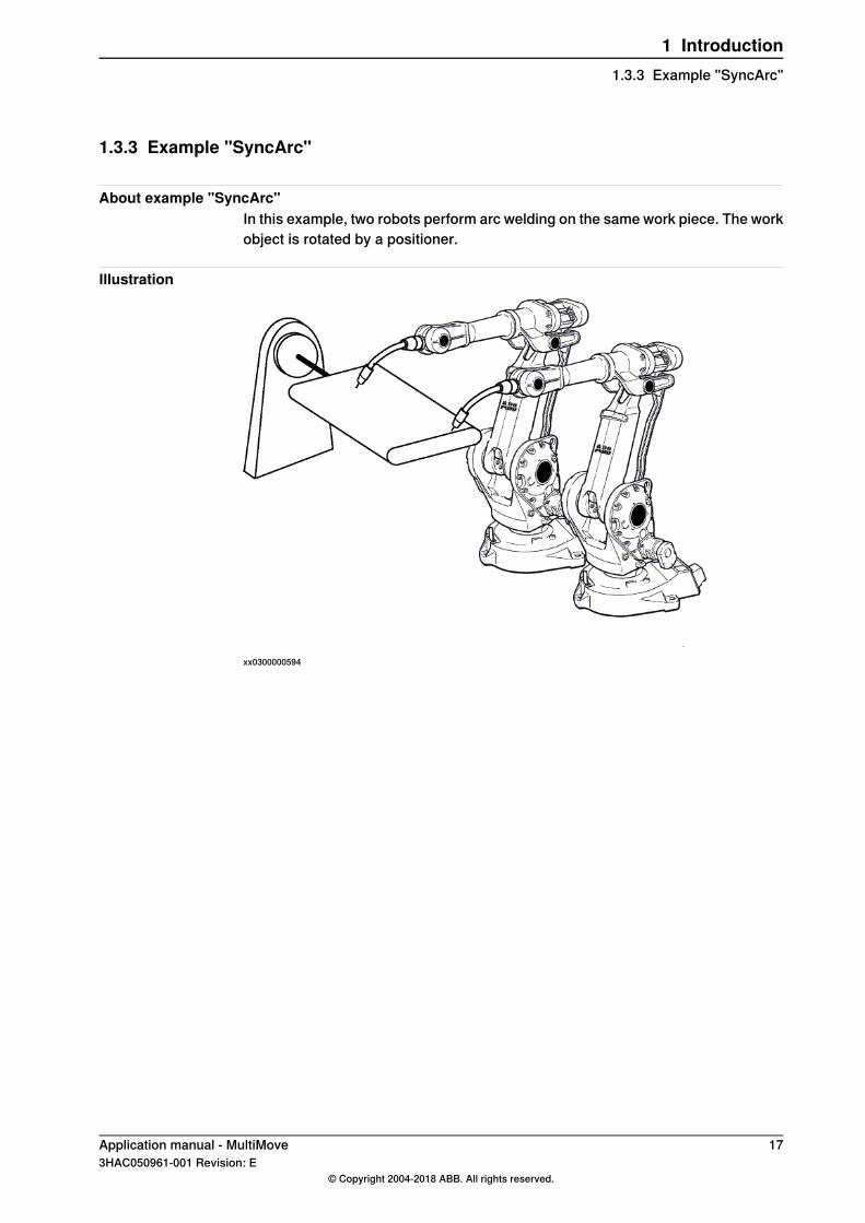
About example "SyncArc"In this example, two robots perform arc welding on the same work piece. The workobject is rotated by a positioner.
Illustration
xx0300000594
Application manual - MultiMove 173HAC050961-001 Revision: E
© Copyright 2004-2018 ABB. All rights reserved.
1 Introduction1.3.3 Example "SyncArc"

This page is intentionally left blank
2 Installation2.1 Hardware installation
2.1.1 About the hardware installation
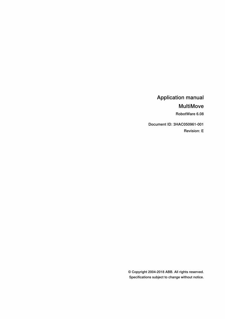
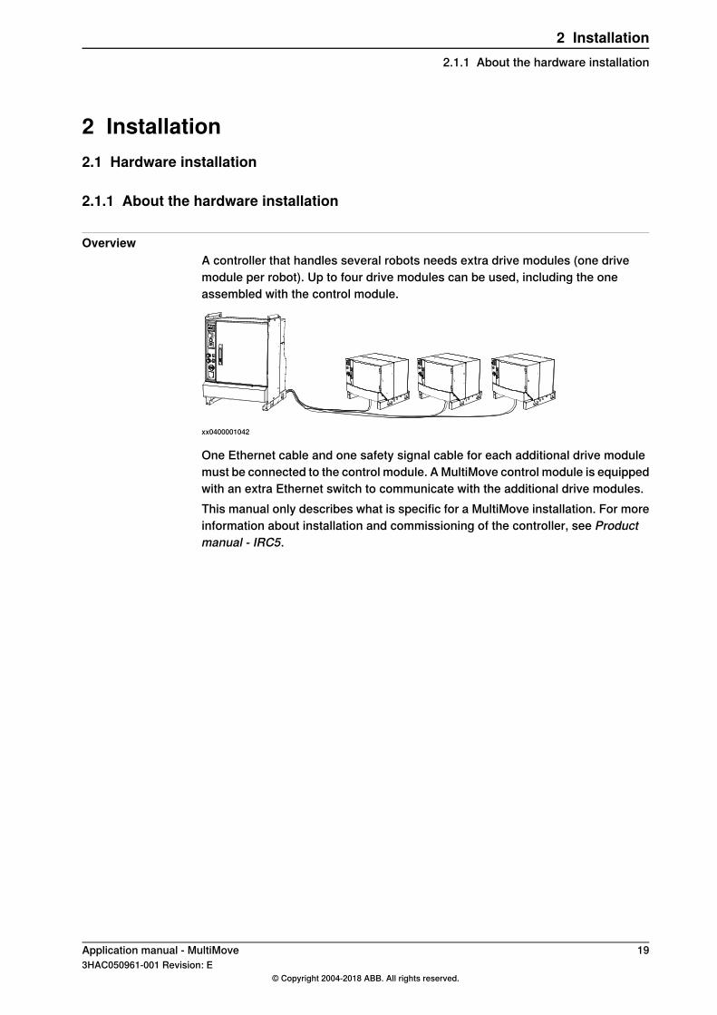
OverviewA controller that handles several robots needs extra drive modules (one drivemodule per robot). Up to four drive modules can be used, including the oneassembled with the control module.
xx0400001042
One Ethernet cable and one safety signal cable for each additional drive modulemust be connected to the control module. A MultiMove control module is equippedwith an extra Ethernet switch to communicate with the additional drive modules.This manual only describes what is specific for a MultiMove installation. For moreinformation about installation and commissioning of the controller, see Productmanual - IRC5.
Application manual - MultiMove 193HAC050961-001 Revision: E
© Copyright 2004-2018 ABB. All rights reserved.
2 Installation2.1.1 About the hardware installation
2.1.2 Connections on the control module
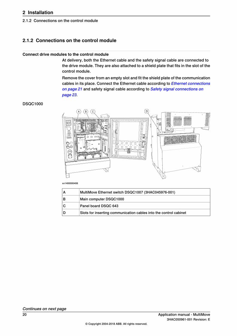
Connect drive modules to the control moduleAt delivery, both the Ethernet cable and the safety signal cable are connected tothe drive module. They are also attached to a shield plate that fits in the slot of thecontrol module.Remove the cover from an empty slot and fit the shield plate of the communicationcables in its place. Connect the Ethernet cable according to Ethernet connectionson page 21 and safety signal cable according to Safety signal connections onpage 23.
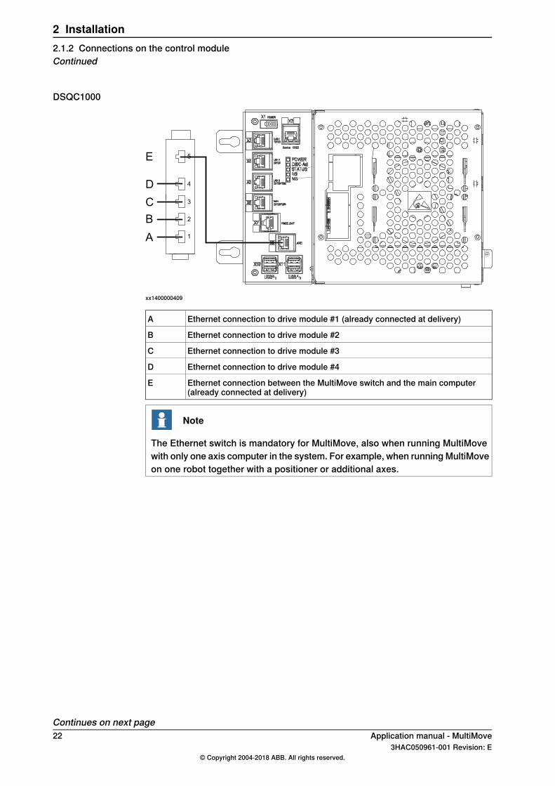
DSQC1000
CBA CBA DD
xx1400000408
MultiMove Ethernet switch DSQC1007 (3HAC045976-001)A
Main computer DSQC1000B
Panel board DSQC 643C
Slots for inserting communication cables into the control cabinetD
Continues on next page20 Application manual - MultiMove
3HAC050961-001 Revision: E© Copyright 2004-2018 ABB. All rights reserved.
2 Installation2.1.2 Connections on the control module
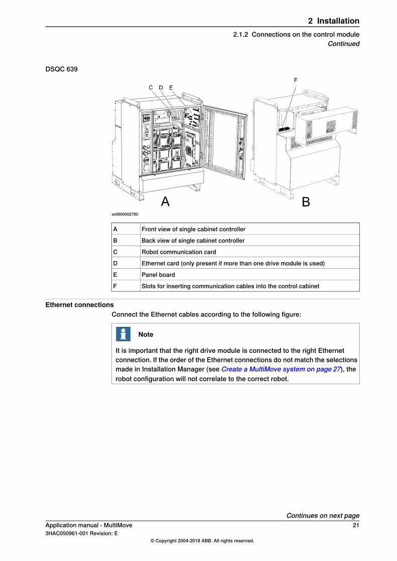
DSQC 639
xx0600002780
Front view of single cabinet controllerA
Back view of single cabinet controllerB
Robot communication cardC
Ethernet card (only present if more than one drive module is used)D
Panel boardE
Slots for inserting communication cables into the control cabinetF
Ethernet connectionsConnect the Ethernet cables according to the following figure:
Note
It is important that the right drive module is connected to the right Ethernetconnection. If the order of the Ethernet connections do not match the selectionsmade in Installation Manager (see Create a MultiMove system on page 27), therobot configuration will not correlate to the correct robot.
Continues on next pageApplication manual - MultiMove 213HAC050961-001 Revision: E
© Copyright 2004-2018 ABB. All rights reserved.
2 Installation2.1.2 Connections on the control module
Continued
DSQC1000
1
2
3
4
5
A
B
C
D
E
xx1400000409
Ethernet connection to drive module #1 (already connected at delivery)A
Ethernet connection to drive module #2B
Ethernet connection to drive module #3C
Ethernet connection to drive module #4D
Ethernet connection between the MultiMove switch and the main computer(already connected at delivery)
E
Note
The Ethernet switch is mandatory for MultiMove, also when running MultiMovewith only one axis computer in the system. For example, when running MultiMoveon one robot together with a positioner or additional axes.
Continues on next page22 Application manual - MultiMove
3HAC050961-001 Revision: E© Copyright 2004-2018 ABB. All rights reserved.
2 Installation2.1.2 Connections on the control moduleContinued
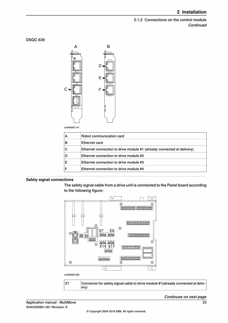
DSQC 639
xx0400001141
Robot communication cardA
Ethernet cardB
Ethernet connection to drive module #1 (already connected at delivery)C
Ethernet connection to drive module #2D
Ethernet connection to drive module #3E
Ethernet connection to drive module #4F
Safety signal connectionsThe safety signal cable from a drive unit is connected to the Panel board accordingto the following figure:
xx0400001295
Connector for safety signal cable to drive module #1(already connected at deliv-ery)
X7
Continues on next pageApplication manual - MultiMove 233HAC050961-001 Revision: E
© Copyright 2004-2018 ABB. All rights reserved.
2 Installation2.1.2 Connections on the control module
Continued
Connector for safety signal cable to drive module #2X8
Connector for safety signal cable to drive module #3X14
Connector for safety signal cable to drive module #4X17
Remove the jumper connector and replace it with the safety signal cable.
24 Application manual - MultiMove3HAC050961-001 Revision: E
© Copyright 2004-2018 ABB. All rights reserved.
2 Installation2.1.2 Connections on the control moduleContinued
2.1.3 Connections on the drive module
Already connected at deliveryWhen a MultiMove system is delivered from ABB, the Ethernet cable and the safetysignal cable are already connected to the drive module. You only need to knowhow these cables are connected if you are going to change the hardwareconfiguration or replace parts.
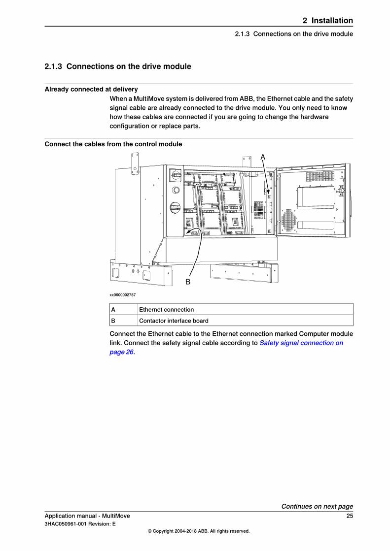
Connect the cables from the control module
A
B
xx0600002787
Ethernet connectionA
Contactor interface boardB
Connect the Ethernet cable to the Ethernet connection marked Computer modulelink. Connect the safety signal cable according to Safety signal connection onpage 26.
Continues on next pageApplication manual - MultiMove 253HAC050961-001 Revision: E
© Copyright 2004-2018 ABB. All rights reserved.
2 Installation2.1.3 Connections on the drive module
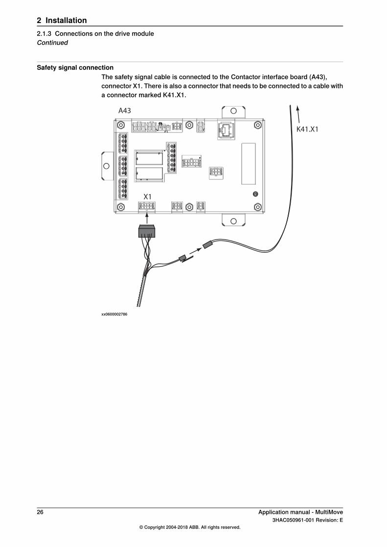
Safety signal connectionThe safety signal cable is connected to the Contactor interface board (A43),connector X1. There is also a connector that needs to be connected to a cable witha connector marked K41.X1.
A43
X1
K41.X1
xx0600002786
26 Application manual - MultiMove3HAC050961-001 Revision: E
© Copyright 2004-2018 ABB. All rights reserved.
2 Installation2.1.3 Connections on the drive moduleContinued
2.2 Software installation
2.2.1 Software installation
Install RobotStudio and RobotWareInstallation of RobotStudio and RobotWare on a PC is described in Operatingmanual - Getting started, IRC5 and RobotStudio.
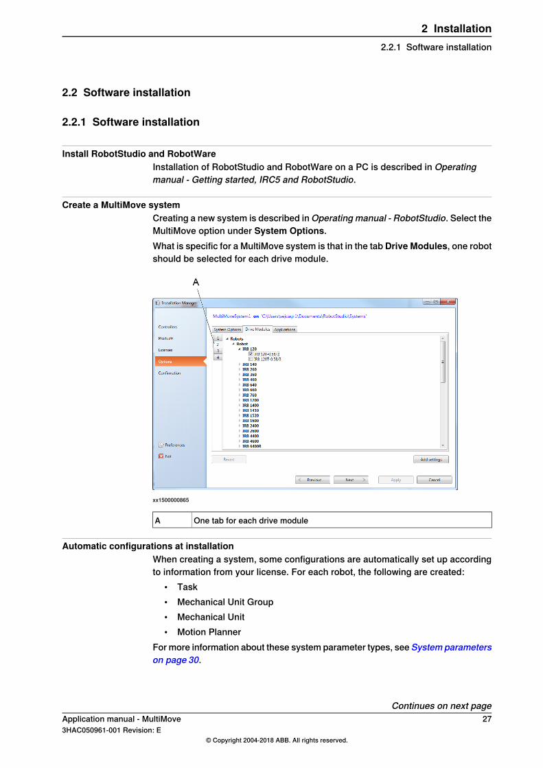
Create a MultiMove systemCreating a new system is described in Operating manual - RobotStudio. Select theMultiMove option under System Options.What is specific for a MultiMove system is that in the tab Drive Modules, one robotshould be selected for each drive module.
xx1500000865
One tab for each drive moduleA
Automatic configurations at installationWhen creating a system, some configurations are automatically set up accordingto information from your license. For each robot, the following are created:
• Task• Mechanical Unit Group• Mechanical Unit• Motion Planner
For more information about these system parameter types, see System parameterson page 30.
Continues on next pageApplication manual - MultiMove 273HAC050961-001 Revision: E
© Copyright 2004-2018 ABB. All rights reserved.
2 Installation2.2.1 Software installation

CAUTION
A motion planner (type Motion Planner), created by the installation process, isconfigured to optimize the movement for its specific robot. If the defaultconfiguration is changed so that a robot uses the wrong motion planner, therobot motion will be affected.
28 Application manual - MultiMove3HAC050961-001 Revision: E
© Copyright 2004-2018 ABB. All rights reserved.
2 Installation2.2.1 Software installationContinued
3 Configuration3.1 Configuration overview
About the system parametersThis chapter contains a brief description of each parameter that is specific forMultiMove. Parameters that are used the same way as for a single robot systemare not mentioned here.For more information about system parameters, see Technical referencemanual - System parameters.
About the examplesThe first three examples cover the topics Controller and Motion, since these arerelated to the physical constellation of the robot system. The last example coversthe topic I/O System, which is handled similarly regardless of the robot system.
Application manual - MultiMove 293HAC050961-001 Revision: E
© Copyright 2004-2018 ABB. All rights reserved.
3 Configuration3.1 Configuration overview
3.2 System parameters
3.2.1 Controller topic
TaskThese parameters belong to the type Task in the topic Controller:
DescriptionParameter
The name of the task.TaskNote that the name of the task must be unique. This means that it cannothave the same name as the mechanical unit, and no variable in theRAPID program can have the same name.
Controls the start/stop and system restart behavior:• NORMAL - The task program is manually started and stopped
(e.g. from the FlexPendant). The task stops at emergency stop.• STATIC - At a restart the task program continues from where it
was. The task program cannot be stopped from the FlexPendantor by emergency stop.
• SEMISTATIC - The task program starts from the beginning at re-start. The task program cannot be stopped from the FlexPendantor by emergency stop.
A task that controls a mechanical unit must be of the type NORMAL.
Type
Indicates whether the task program can control a mechanical unit withRAPID move instructions.
MotionTask
Defines which mechanical unit group is used for the task.Use MechanicalUnit Group Use Mechanical Unit Group refers to the parameter Name for the type
Mechanical Unit Group.A motion task (MotionTask set to Yes) controls the mechanical units inthe mechanical unit group. A non-motion task (MotionTask set to No)will still be able to read values (e.g. the TCP position) for the activemechanical units in the mechanical unit group.Note that Use Mechanical Unit Group must be defined for all tasks, evenif the task does not control any mechanical unit.
Mechanical Unit GroupA mechanical unit group must contain at least one mechanical unit, robot or othermechanical unit (i.e. both Robot and Mech Unit 1 cannot be left empty).These parameters belong to the typeMechanical Unit Group in the topicController:
DescriptionParameter
The name of the mechanical unit group.Name
Specifies the robot (with TCP), if there is any, in the mechanical unit group.RobotRobot refers to the parameter Name for the type Mechanical Unit in thetopic Motion.
Specifies a mechanical unit without TCP, if there is any, in the mechanicalunit group.
Mech Unit 1
Mech Unit 1 refers to the parameter Name for the type Mechanical Unit inthe topic Motion.
Specifies the second mechanical unit without TCP, if there are more thanone, in the mechanical unit group.
Mech Unit 2
Mech Unit 2 refers to the parameter Name for the type Mechanical Unitin the topic Motion.
Continues on next page30 Application manual - MultiMove
3HAC050961-001 Revision: E© Copyright 2004-2018 ABB. All rights reserved.
3 Configuration3.2.1 Controller topic
DescriptionParameter
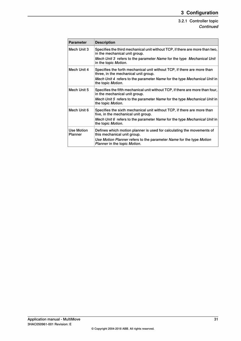
Specifies the third mechanical unit without TCP, if there are more than two,in the mechanical unit group.
Mech Unit 3
Mech Unit 3 refers to the parameter Name for the type Mechanical Unitin the topic Motion.
Specifies the forth mechanical unit without TCP, if there are more thanthree, in the mechanical unit group.
Mech Unit 4
Mech Unit 4 refers to the parameter Name for the type Mechanical Unit inthe topic Motion.
Specifies the fifth mechanical unit without TCP, if there are more than four,in the mechanical unit group.
Mech Unit 5
Mech Unit 5 refers to the parameter Name for the type Mechanical Unit inthe topic Motion.
Specifies the sixth mechanical unit without TCP, if there are more thanfive, in the mechanical unit group.
Mech Unit 6
Mech Unit 6 refers to the parameter Name for the type Mechanical Unit inthe topic Motion.
Defines which motion planner is used for calculating the movements ofthis mechanical unit group.
Use MotionPlanner
Use Motion Planner refers to the parameter Name for the type MotionPlanner in the topic Motion.
Application manual - MultiMove 313HAC050961-001 Revision: E
© Copyright 2004-2018 ABB. All rights reserved.
3 Configuration3.2.1 Controller topic
Continued
3.2.2 Motion topic
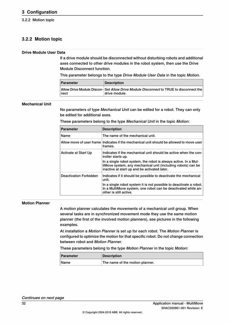
Drive Module User DataIf a drive module should be disconnected without disturbing robots and additionalaxes connected to other drive modules in the robot system, then use the DriveModule Disconnect function.This parameter belongs to the type Drive Module User Data in the topic Motion.
DescriptionParameter
Set Allow Drive Module Disconnect to TRUE to disconnect thedrive module.
Allow Drive Module Discon-nect
Mechanical UnitNo parameters of type Mechanical Unit can be edited for a robot. They can onlybe edited for additional axes.These parameters belong to the type Mechanical Unit in the topic Motion:
DescriptionParameter
The name of the mechanical unit.Name
Indicates if the mechanical unit should be allowed to move userframes.
Allow move of user frame
Indicates if the mechanical unit should be active when the con-troller starts up.
Activate at Start Up
In a single robot system, the robot is always active. In a Mul-tiMove system, any mechanical unit (including robots) can beinactive at start up and be activated later.
Indicates if it should be possible to deactivate the mechanicalunit.
Deactivation Forbidden
In a single robot system it is not possible to deactivate a robot.In a MultiMove system, one robot can be deactivated while an-other is still active.
Motion PlannerA motion planner calculates the movements of a mechanical unit group. Whenseveral tasks are in synchronized movement mode they use the same motionplanner (the first of the involved motion planners), see pictures in the followingexamples.At installation a Motion Planner is set up for each robot. The Motion Planner isconfigured to optimize the motion for that specific robot. Do not change connectionbetween robot and Motion Planner.These parameters belong to the type Motion Planner in the topic Motion:
DescriptionParameter
The name of the motion planner.Name
Continues on next page32 Application manual - MultiMove
3HAC050961-001 Revision: E© Copyright 2004-2018 ABB. All rights reserved.
3 Configuration3.2.2 Motion topic
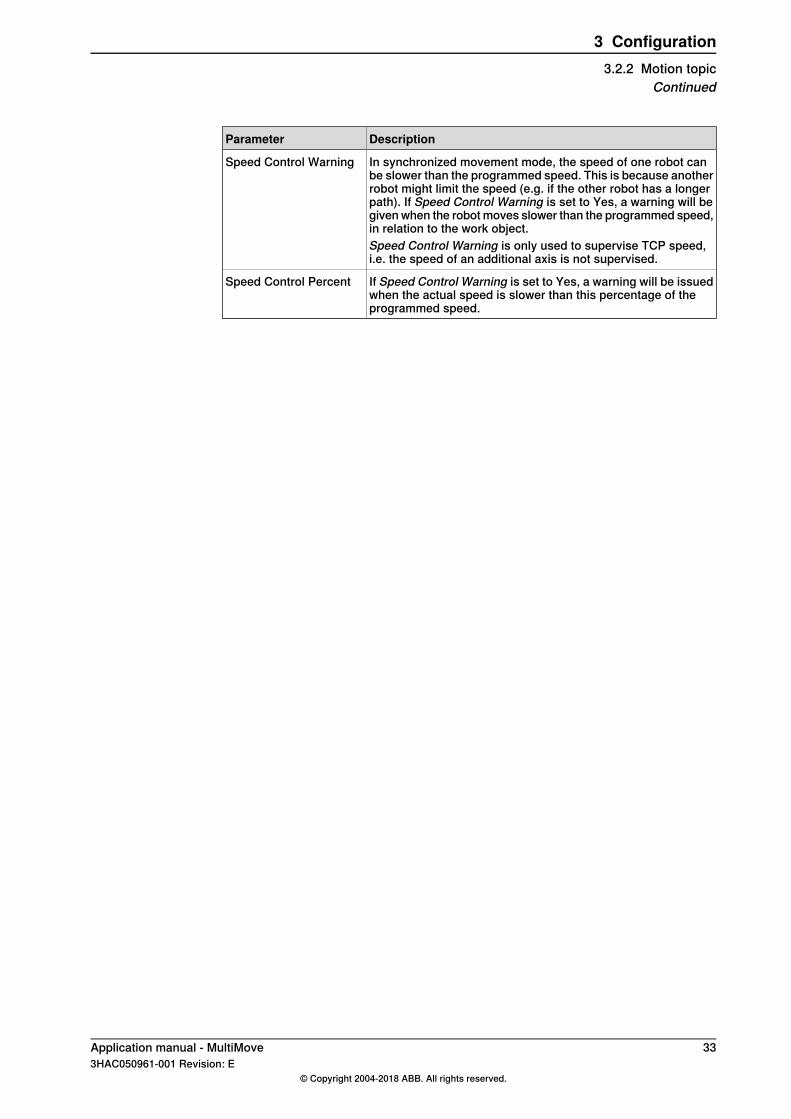
DescriptionParameter
In synchronized movement mode, the speed of one robot canbe slower than the programmed speed. This is because anotherrobot might limit the speed (e.g. if the other robot has a longerpath). If Speed Control Warning is set to Yes, a warning will begiven when the robot moves slower than the programmed speed,in relation to the work object.
Speed Control Warning
Speed Control Warning is only used to supervise TCP speed,i.e. the speed of an additional axis is not supervised.
If Speed Control Warning is set to Yes, a warning will be issuedwhen the actual speed is slower than this percentage of theprogrammed speed.
Speed Control Percent
Application manual - MultiMove 333HAC050961-001 Revision: E
© Copyright 2004-2018 ABB. All rights reserved.
3 Configuration3.2.2 Motion topic
Continued
3.2.3 I/O topic
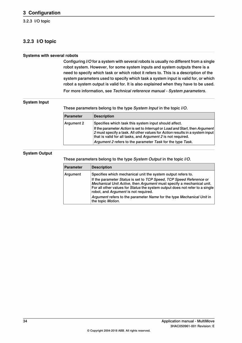
Systems with several robotsConfiguring I/O for a system with several robots is usually no different from a singlerobot system. However, for some system inputs and system outputs there is aneed to specify which task or which robot it refers to. This is a description of thesystem parameters used to specify which task a system input is valid for, or whichrobot a system output is valid for. It is also explained when they have to be used.For more information, see Technical reference manual - System parameters.
System InputThese parameters belong to the type System Input in the topic I/O.
DescriptionParameter
Specifies which task this system input should affect.Argument 2If the parameterAction is set to Interrupt or Load and Start, thenArgument2 must specify a task. All other values forAction results in a system inputthat is valid for all tasks, and Argument 2 is not required.Argument 2 refers to the parameter Task for the type Task.
System OutputThese parameters belong to the type System Output in the topic I/O.
DescriptionParameter
Specifies which mechanical unit the system output refers to.ArgumentIf the parameter Status is set to TCP Speed, TCP Speed Reference orMechanical Unit Active, then Argument must specify a mechanical unit.For all other values for Status the system output does not refer to a singlerobot, and Argument is not required.Argument refers to the parameter Name for the type Mechanical Unit inthe topic Motion.
34 Application manual - MultiMove3HAC050961-001 Revision: E
© Copyright 2004-2018 ABB. All rights reserved.
3 Configuration3.2.3 I/O topic
3.3 Configuration examples
3.3.1 Configuration example for "UnsyncArc"
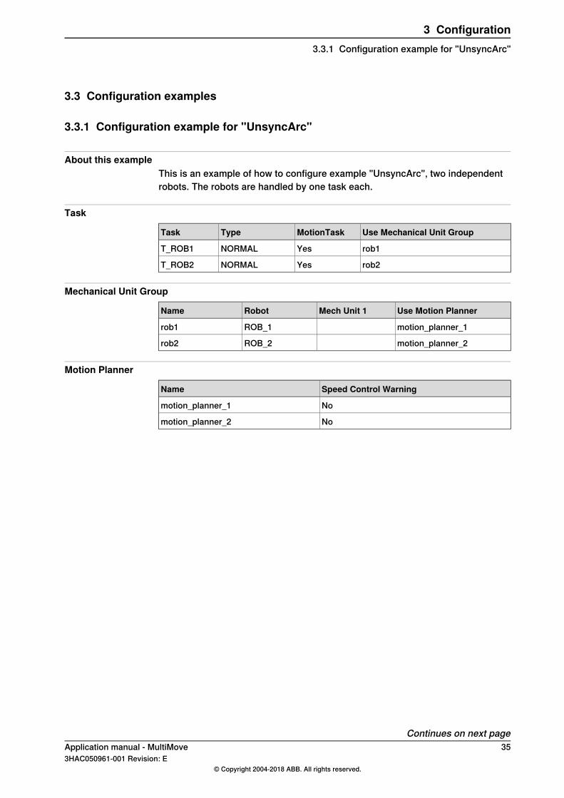
About this exampleThis is an example of how to configure example "UnsyncArc", two independentrobots. The robots are handled by one task each.
Task
Use Mechanical Unit GroupMotionTaskTypeTask
rob1YesNORMALT_ROB1
rob2YesNORMALT_ROB2
Mechanical Unit Group
Use Motion PlannerMech Unit 1RobotName
motion_planner_1ROB_1rob1
motion_planner_2ROB_2rob2
Motion Planner
Speed Control WarningName
Nomotion_planner_1
Nomotion_planner_2
Continues on next pageApplication manual - MultiMove 353HAC050961-001 Revision: E
© Copyright 2004-2018 ABB. All rights reserved.
3 Configuration3.3.1 Configuration example for "UnsyncArc"
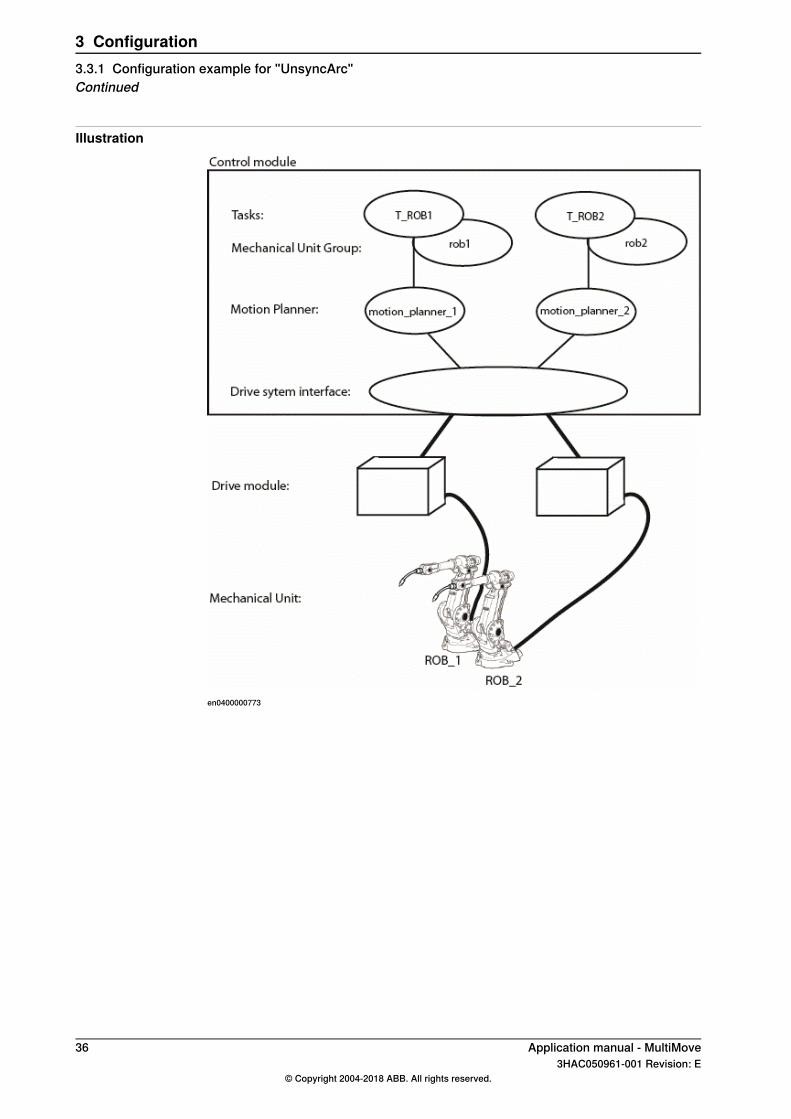
Illustration
en0400000773
36 Application manual - MultiMove3HAC050961-001 Revision: E
© Copyright 2004-2018 ABB. All rights reserved.
3 Configuration3.3.1 Configuration example for "UnsyncArc"Continued
3.3.2 Configuration example for "SyncArc"
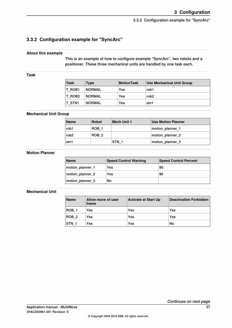
About this exampleThis is an example of how to configure example "SyncArc", two robots and apositioner. These three mechanical units are handled by one task each.
Task
Use Mechanical Unit GroupMotionTaskTypeTask
rob1YesNORMALT_ROB1
rob2YesNORMALT_ROB2
stn1YesNORMALT_STN1
Mechanical Unit Group
Use Motion PlannerMech Unit 1RobotName
motion_planner_1ROB_1rob1
motion_planner_2ROB_2rob2
motion_planner_3STN_1stn1
Motion Planner
Speed Control PercentSpeed Control WarningName
90Yesmotion_planner_1
90Yesmotion_planner_2
Nomotion_planner_3
Mechanical Unit
Deactivation ForbiddenActivate at Start UpAllow move of userframe
Name
YesYesYesROB_1
YesYesYesROB_2
NoYesYesSTN_1
Continues on next pageApplication manual - MultiMove 373HAC050961-001 Revision: E
© Copyright 2004-2018 ABB. All rights reserved.
3 Configuration3.3.2 Configuration example for "SyncArc"
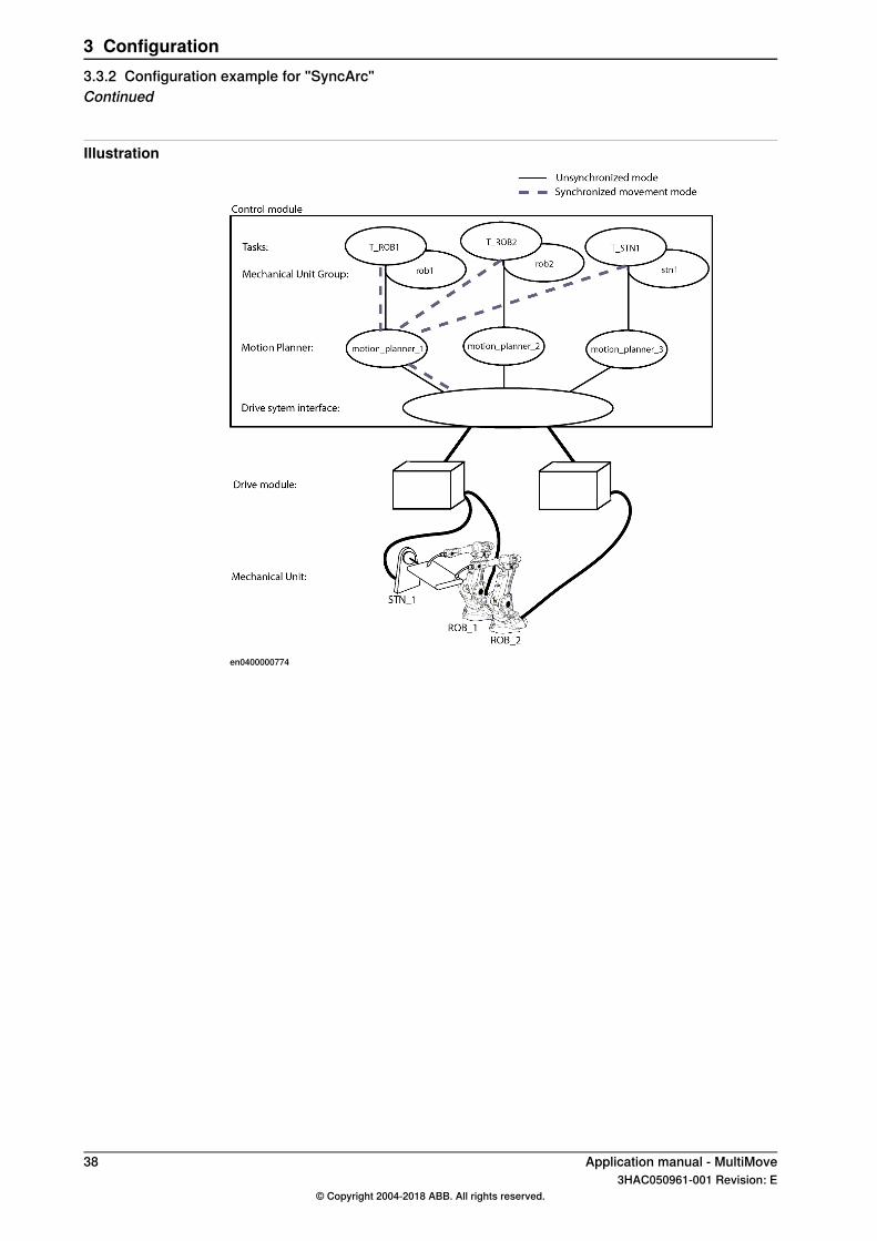
Illustration
en0400000774
38 Application manual - MultiMove3HAC050961-001 Revision: E
© Copyright 2004-2018 ABB. All rights reserved.
3 Configuration3.3.2 Configuration example for "SyncArc"Continued
3.3.3 I/O configuration example
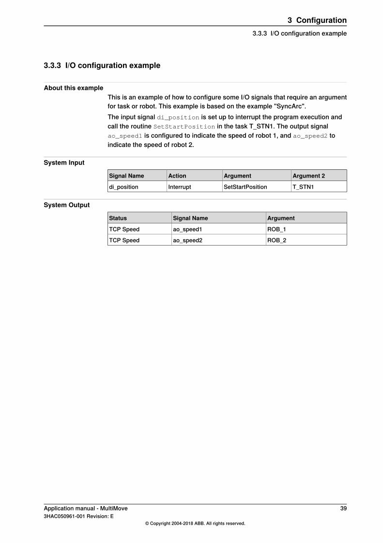
About this exampleThis is an example of how to configure some I/O signals that require an argumentfor task or robot. This example is based on the example "SyncArc".The input signal di_position is set up to interrupt the program execution andcall the routine SetStartPosition in the task T_STN1. The output signalao_speed1 is configured to indicate the speed of robot 1, and ao_speed2 toindicate the speed of robot 2.
System Input
Argument 2ArgumentActionSignal Name
T_STN1SetStartPositionInterruptdi_position
System Output
ArgumentSignal NameStatus
ROB_1ao_speed1TCP Speed
ROB_2ao_speed2TCP Speed
Application manual - MultiMove 393HAC050961-001 Revision: E
© Copyright 2004-2018 ABB. All rights reserved.
3 Configuration3.3.3 I/O configuration example

This page is intentionally left blank
4 Calibration4.1 Calibration overview
Two types of calibrationThere are two types of calibration that must be done for a robot system:
1 Joint calibration ensures that all axes are in correct position. Normally thisis done before delivery of a new robot and only requires recalibration afterrepairing the robot. For more information, see the product manual for therespective robot.
2 Calibration of coordinate systems must be made when the robot is in place.A brief description of what coordinate systems to calibrate and in which orderis presented below.
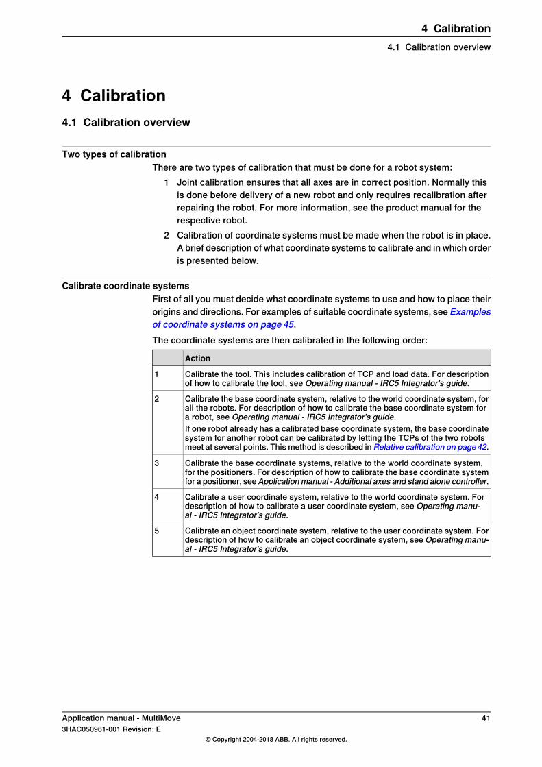
Calibrate coordinate systemsFirst of all you must decide what coordinate systems to use and how to place theirorigins and directions. For examples of suitable coordinate systems, see Examplesof coordinate systems on page 45.The coordinate systems are then calibrated in the following order:
Action
Calibrate the tool. This includes calibration of TCP and load data. For descriptionof how to calibrate the tool, see Operating manual - IRC5 Integrator's guide.
1
Calibrate the base coordinate system, relative to the world coordinate system, forall the robots. For description of how to calibrate the base coordinate system fora robot, see Operating manual - IRC5 Integrator's guide.
2
If one robot already has a calibrated base coordinate system, the base coordinatesystem for another robot can be calibrated by letting the TCPs of the two robotsmeet at several points. This method is described in Relative calibration on page42.
Calibrate the base coordinate systems, relative to the world coordinate system,for the positioners. For description of how to calibrate the base coordinate systemfor a positioner, seeApplicationmanual - Additional axes and stand alone controller.
3
Calibrate a user coordinate system, relative to the world coordinate system. Fordescription of how to calibrate a user coordinate system, see Operating manu-al - IRC5 Integrator's guide.
4
Calibrate an object coordinate system, relative to the user coordinate system. Fordescription of how to calibrate an object coordinate system, see Operating manu-al - IRC5 Integrator's guide.
5
Application manual - MultiMove 413HAC050961-001 Revision: E
© Copyright 2004-2018 ABB. All rights reserved.
4 Calibration4.1 Calibration overview
4.2 Relative calibration
What is relative calibrationRelative calibration is used to calibrate the base coordinate system of one robot,using a robot that is already calibrated. This calibration method can only be usedfor a MultiMove system where two robots are placed close enough to have somepart of their working areas in common.If one robot has a base coordinate system that is identical with the world coordinatesystem, this robot can be used as a reference for another robot. If no robot has abase coordinate system that is identical with the world coordinate system, the basecoordinate system for one robot must be calibrated first. For information aboutother calibration methods, see Operating manual - IRC5 Integrator's guide.
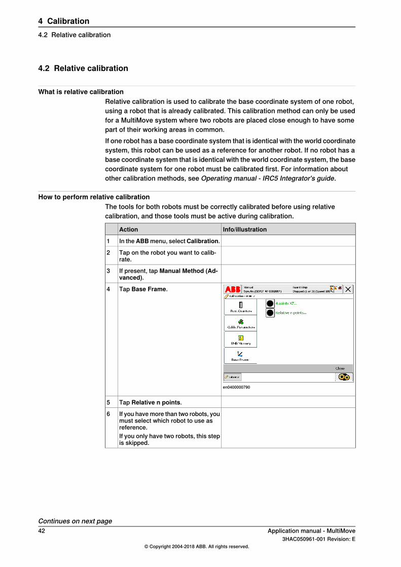
How to perform relative calibrationThe tools for both robots must be correctly calibrated before using relativecalibration, and those tools must be active during calibration.
Info/illustrationAction
In the ABBmenu, selectCalibration.1
Tap on the robot you want to calib-rate.
2
If present, tap Manual Method (Ad-vanced).
3
en0400000790
Tap Base Frame.4
Tap Relative n points.5
If you have more than two robots, youmust select which robot to use asreference.
6
If you only have two robots, this stepis skipped.
Continues on next page42 Application manual - MultiMove
3HAC050961-001 Revision: E© Copyright 2004-2018 ABB. All rights reserved.
4 Calibration4.2 Relative calibration
Info/illustrationAction
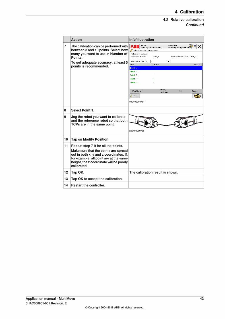
en0400000791
The calibration can be performed withbetween 3 and 10 points. Select howmany you want to use in Number ofPoints.To get adequate accuracy, at least 5points is recommended.
7
Select Point 1.8
xx0400000785
Jog the robot you want to calibrateand the reference robot so that bothTCPs are in the same point.
9
Tap on Modify Position.10
Repeat step 7-9 for all the points.11Make sure that the points are spreadout in both x, y and z coordinates. If,for example, all point are at the sameheight, the z coordinate will be poorlycalibrated.
The calibration result is shown.Tap OK.12
Tap OK to accept the calibration.13
Restart the controller.14
Application manual - MultiMove 433HAC050961-001 Revision: E
© Copyright 2004-2018 ABB. All rights reserved.
4 Calibration4.2 Relative calibration
Continued
4.3 Calibration chains
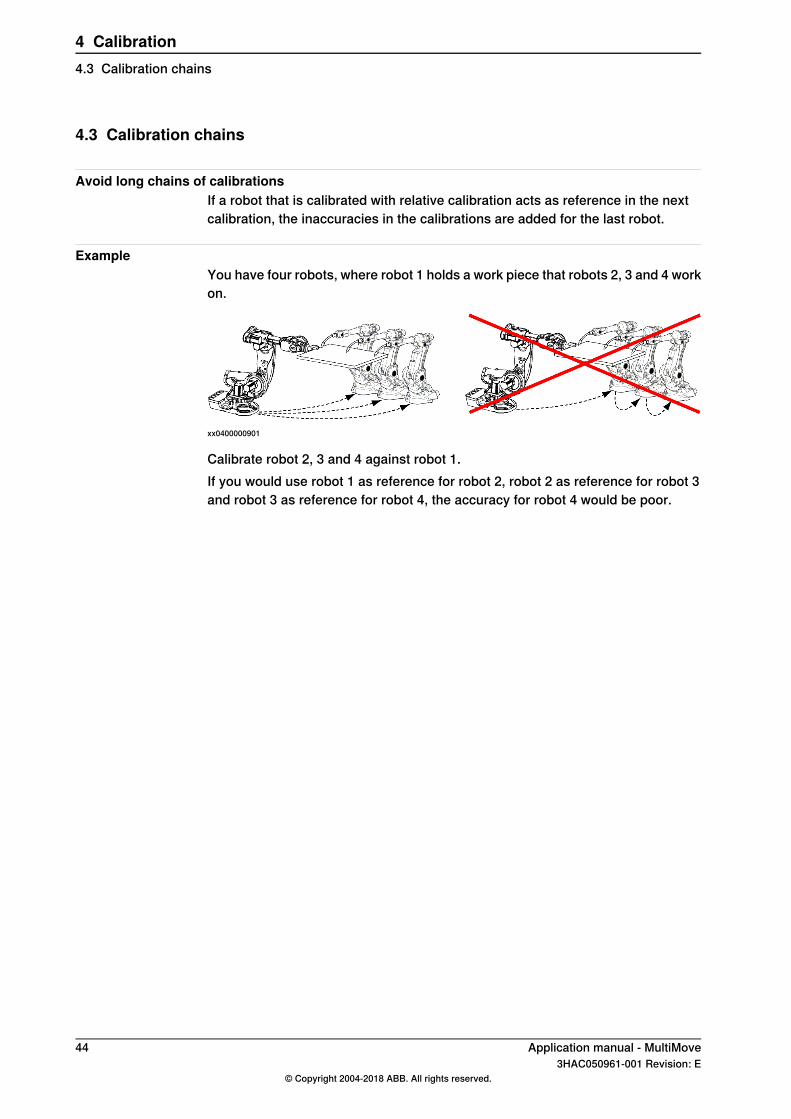
Avoid long chains of calibrationsIf a robot that is calibrated with relative calibration acts as reference in the nextcalibration, the inaccuracies in the calibrations are added for the last robot.
ExampleYou have four robots, where robot 1 holds a work piece that robots 2, 3 and 4 workon.
xx0400000901
Calibrate robot 2, 3 and 4 against robot 1.If you would use robot 1 as reference for robot 2, robot 2 as reference for robot 3and robot 3 as reference for robot 4, the accuracy for robot 4 would be poor.
44 Application manual - MultiMove3HAC050961-001 Revision: E
© Copyright 2004-2018 ABB. All rights reserved.
4 Calibration4.3 Calibration chains
4.4 Examples of coordinate systems
4.4.1 Example "UnsyncArc"
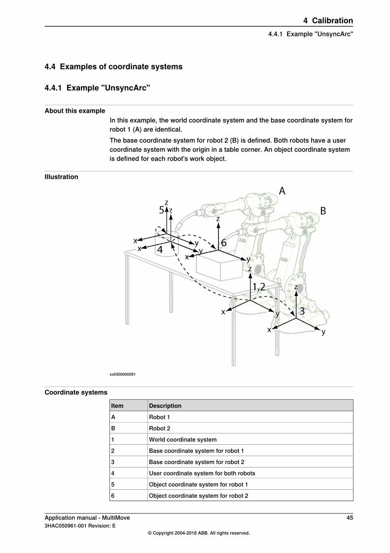
About this exampleIn this example, the world coordinate system and the base coordinate system forrobot 1 (A) are identical.The base coordinate system for robot 2 (B) is defined. Both robots have a usercoordinate system with the origin in a table corner. An object coordinate systemis defined for each robot's work object.
Illustration
xx0300000591
Coordinate systems
DescriptionItem
Robot 1A
Robot 2B
World coordinate system1
Base coordinate system for robot 12
Base coordinate system for robot 23
User coordinate system for both robots4
Object coordinate system for robot 15
Object coordinate system for robot 26
Application manual - MultiMove 453HAC050961-001 Revision: E
© Copyright 2004-2018 ABB. All rights reserved.
4 Calibration4.4.1 Example "UnsyncArc"
4.4.2 Example "SyncArc"
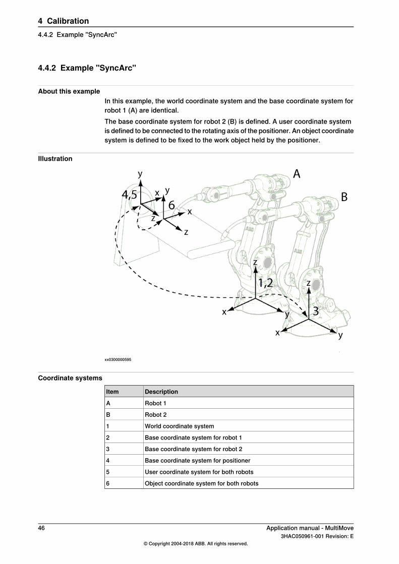
About this exampleIn this example, the world coordinate system and the base coordinate system forrobot 1 (A) are identical.The base coordinate system for robot 2 (B) is defined. A user coordinate systemis defined to be connected to the rotating axis of the positioner. An object coordinatesystem is defined to be fixed to the work object held by the positioner.
Illustration
xx0300000595
Coordinate systems
DescriptionItem
Robot 1A
Robot 2B
World coordinate system1
Base coordinate system for robot 12
Base coordinate system for robot 23
Base coordinate system for positioner4
User coordinate system for both robots5
Object coordinate system for both robots6
46 Application manual - MultiMove3HAC050961-001 Revision: E
© Copyright 2004-2018 ABB. All rights reserved.
4 Calibration4.4.2 Example "SyncArc"
5 User interface specific for MultiMove5.1 FlexPendant for MultiMove system
About FlexPendant for MultiMove systemWorking with the FlexPendant in a MultiMove system is not very different from asingle robot system. This chapter will explain a few things that are specific for aMultiMove system. For general information about the FlexPendant, see Operatingmanual - IRC5 with FlexPendant.
What is specific for MultiMove?Some things that are specific for MultiMove are:
• The status bar shows which robots (and additional axes) are coordinated.See Status bar indications on page 48.
• When opening the program editor, you must select a task. See Opening theProgram Editor on page 50.
• The Production window contains tabs for different tasks. See ProductionWindow on page 51.
• The mechanical unit menu can contain several robots. See Mechanical unitmenu on page 52.
• You can select which tasks to execute at start. See Select which tasks tostart with START button on page 53.
• There is an additional method for calibrating a robot base frame, relativecalibration. See Relative calibration on page 42.
Application manual - MultiMove 473HAC050961-001 Revision: E
© Copyright 2004-2018 ABB. All rights reserved.
5 User interface specific for MultiMove5.1 FlexPendant for MultiMove system
5.2 Status bar indications
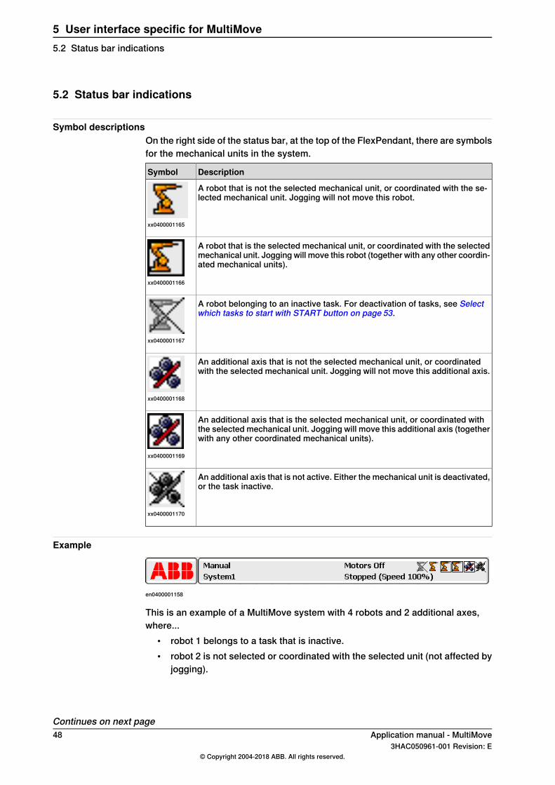
Symbol descriptionsOn the right side of the status bar, at the top of the FlexPendant, there are symbolsfor the mechanical units in the system.
DescriptionSymbol
A robot that is not the selected mechanical unit, or coordinated with the se-lected mechanical unit. Jogging will not move this robot.
xx0400001165
A robot that is the selected mechanical unit, or coordinated with the selectedmechanical unit. Jogging will move this robot (together with any other coordin-ated mechanical units).
xx0400001166
A robot belonging to an inactive task. For deactivation of tasks, see Selectwhich tasks to start with START button on page 53.
xx0400001167
An additional axis that is not the selected mechanical unit, or coordinatedwith the selected mechanical unit. Jogging will not move this additional axis.
xx0400001168
An additional axis that is the selected mechanical unit, or coordinated withthe selected mechanical unit. Jogging will move this additional axis (togetherwith any other coordinated mechanical units).
xx0400001169
An additional axis that is not active. Either the mechanical unit is deactivated,or the task inactive.
xx0400001170
Example
en0400001158
This is an example of a MultiMove system with 4 robots and 2 additional axes,where...
• robot 1 belongs to a task that is inactive.• robot 2 is not selected or coordinated with the selected unit (not affected by
jogging).
Continues on next page48 Application manual - MultiMove
3HAC050961-001 Revision: E© Copyright 2004-2018 ABB. All rights reserved.
5 User interface specific for MultiMove5.2 Status bar indications
• additional axis 1 is selected mechanical unit and robot 3 and 4 are coordinatedwith additional axis 1. Any jogging at this point will move these threemechanical units.
• additional axis 2 is deactivated, or its task inactive.
Application manual - MultiMove 493HAC050961-001 Revision: E
© Copyright 2004-2018 ABB. All rights reserved.
5 User interface specific for MultiMove5.2 Status bar indications
Continued
5.3 Opening the Program Editor
Select taskWhen opening the Program Editor for a system with more than one task, a list ofall the tasks will be displayed. By tapping the task you want, the program code forthat task is displayed.For a system with only one task, this list is never shown. The program code isshown directly.
50 Application manual - MultiMove3HAC050961-001 Revision: E
© Copyright 2004-2018 ABB. All rights reserved.
5 User interface specific for MultiMove5.3 Opening the Program Editor
5.4 Production Window
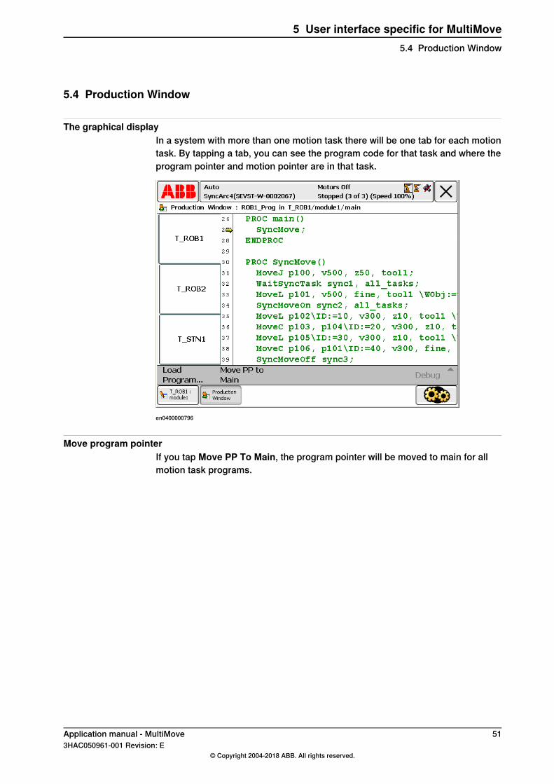
The graphical displayIn a system with more than one motion task there will be one tab for each motiontask. By tapping a tab, you can see the program code for that task and where theprogram pointer and motion pointer are in that task.
en0400000796
Move program pointerIf you tap Move PP To Main, the program pointer will be moved to main for allmotion task programs.
Application manual - MultiMove 513HAC050961-001 Revision: E
© Copyright 2004-2018 ABB. All rights reserved.
5 User interface specific for MultiMove5.4 Production Window
5.5 Mechanical unit menu
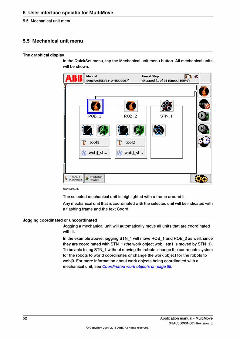
The graphical displayIn the QuickSet menu, tap the Mechanical unit menu button. All mechanical unitswill be shown.
en0400000789
The selected mechanical unit is highlighted with a frame around it.Any mechanical unit that is coordinated with the selected unit will be indicated witha flashing frame and the text Coord.
Jogging coordinated or uncoordinatedJogging a mechanical unit will automatically move all units that are coordinatedwith it.In the example above, jogging STN_1 will move ROB_1 and ROB_2 as well, sincethey are coordinated with STN_1 (the work object wobj_stn1 is moved by STN_1).To be able to jog STN_1 without moving the robots, change the coordinate systemfor the robots to world coordinates or change the work object for the robots towobj0. For more information about work objects being coordinated with amechanical unit, see Coordinated work objects on page 59.
52 Application manual - MultiMove3HAC050961-001 Revision: E
© Copyright 2004-2018 ABB. All rights reserved.
5 User interface specific for MultiMove5.5 Mechanical unit menu
5.6 Select which tasks to start with START button
BackgroundThe default behavior is that the programs of all NORMAL tasks are startedsimultaneously when pressing the START button. However, not all NORMAL taskprograms need to run at the same time. It is possible to select which of the NORMALtask programs will start when pressing the START button.If All Tasks is selected in the Task Panel Settings, the programs of all STATICand SEMISTATIC tasks with TrustLevel set to NoSafety can be selected to bestarted with the START button, forward stepped with the FWD button, backwardstepped with the BWD button, and stopped with the STOP button.If Task Panel Settings is set to Only Normal tasks, all STATIC and SEMISTATICtasks are greyed out and cannot be selected in the task panel, Quickset menu (seeOperating manual - IRC5 with FlexPendant, section Quickset menu). All STATICand SEMISTATIC tasks will be started if the start button is pressed.If Task Panel Settings is set to All tasks, STATIC and SEMISTATIC tasks withTrustLevelNoSafety can be selected in the task panel. All selected STATIC andSEMISTATIC tasks can be stopped, stepped, and started. .A STATIC or SEMISTATIC task, not selected in the task panel, can still be executing.This is not possible for a NORMAL task.Run Mode is always continuous for STATIC and SEMISTATIC tasks. The Run Modesetting in the Quickset menu is only applicable for NORMAL tasks (see Operatingmanual - IRC5 with FlexPendant, section Quickset menu).This will only work in manual mode, no STATIC or SEMISTATIC task can be started,stepped, or stopped in auto mode.
Task Panel SettingsTo start the Task Panel Settings, tap the ABB menu, and then Control Panel,FlexPendant and Task Panel Settings.
Selecting tasksUse this procedure to select which of the tasks are to be started with the STARTbutton.
Action
Set the controller to manual mode.1
On the FlexPendant, tap the QuickSet button and then the tasks panel button to showall tasks.
2
If Task Panel Settings is set toOnly Normal tasks, all STATIC and SEMISTATIC tasksare greyed out and cannot be selected.If Task Panel Settings is set to All tasks, STATIC and SEMISTATIC tasks with Trust-LevelNoSafety can be selected, while STATIC and SEMISTATIC tasks with TrustLevelset to other values are grayed out and cannot be selected.
Select the check boxes for the tasks whose program should be started by the STARTbutton.
3
Continues on next pageApplication manual - MultiMove 533HAC050961-001 Revision: E
© Copyright 2004-2018 ABB. All rights reserved.
5 User interface specific for MultiMove5.6 Select which tasks to start with START button
Resetting debug settings in manual modeUse this procedure to resume normal execution manual mode.
Action
Select Only Normal tasks in the Task Panel Settings.1
Press START button.2All STATIC and SEMISTATIC will run continuously and not be stopped by the STOPbutton or emergency stop.
Switching to auto modeWhen switching to auto mode, all STATIC and SEMISTATIC tasks will be deselectedfrom the tasks panel. The stopped STATIC and SEMISTATIC tasks will start nexttime any of the START, FWD or BWD button are pressed. These tasks will thenrun continuously forward and not be stopped by the STOP button or emergencystop.What happens with NORMAL tasks that has been deselected in the tasks paneldepends on the system parameter Reset in type Auto Condition Reset in topicController. If Reset is set to Yes, all NORMAL tasks will be selected in the taskspanel and be started with the START button. If Reset is set to No, only thoseNORMAL tasks selected in tasks panel will be started by the START button.
Note
Note that changing the value of the system parameter Reset will affect all thedebug resettings (for example speed override and simulated I/O). For moreinformation, see Technical reference manual - System parameters, section AutoCondition Reset.
Restarting the controllerIf the controller is restarted, all NORMAL tasks will keep their status while allSTATIC and SEMISTATIC tasks will be deselected from the tasks panel. As thecontroller starts up all STATIC and SEMISTATIC tasks will be started and then runcontinuously.
Deselect task in synchronized modeIf a task is in a synchronized mode, that is program pointer between SyncMoveOn
and SyncMoveOff, the task can be deselected but not reselected. The task cannotbe selected until the synchronization is terminated. If the execution continues, thesynchronization will eventually be terminated for the other tasks, but not for thedeselected task. The synchronization can be terminated for this task by movingthe program pointer to main or to a routine.If the system parameter Reset is set to Yes, any attempt to change to Auto modewill fail while a deselected task is in synchronized mode. Changing to Auto modeshould make all NORMAL tasks selected, and when this is not possible it is notpossible to change to Auto mode.
54 Application manual - MultiMove3HAC050961-001 Revision: E
© Copyright 2004-2018 ABB. All rights reserved.
5 User interface specific for MultiMove5.6 Select which tasks to start with START buttonContinued
6 Programming6.1 RAPID components
Data typesThis is a brief description of each data type in MultiMove. For more information,see the respective data type in Technical reference manual - RAPID Instructions,Functions and Data types.
DescriptionData type
A variable of the data type syncident is used to identify whichWaitSyncTask, SyncMoveOn or SyncMoveOff instructions, in the differ-ent task programs, should be synchronized with each other.
syncident
The name of the syncident variable must be the same in all task pro-grams.Declare syncident variables globally in each task. Do not reuse asyncident variable (each WaitSyncTask, SyncMoveOn andSyncMoveOff in a task program should have a unique syncident).
A persistent variable of the data type tasks contains names of the tasksthat will be synchronized with WaitSyncTask or SyncMoveOn.
tasks
The tasks variable must be declared as system global (persistent)variable, with the same name and the same content in all task programs.
A numeric value or a variable of type identno is used in the argumentID of any move instructions executed between the SyncMoveOn andSyncMoveOff instructions.
identno
System dataSystem data is predefined, internal data of the robot. A system data can be read,but not changed, from a RAPID program. For more information, see Technicalreference manual - RAPID Instructions, Functions and Data types.
DescriptionSystem data
Reference to the robot (if any) controlled by the task.ROB_IDIf used from a task that does not control a robot, an error will occur. Al-ways use TaskRunRob() to check this before using ROB_ID.
InstructionsThis is a brief description of each instruction in MultiMove. For more information,see the respective instruction in Technical reference manual - RAPID Instructions,Functions and Data types.
DescriptionInstruction
WaitSyncTask is used to synchronize several task programs at a specialpoint in the program.
WaitSyncTask
A WaitSyncTask instruction will wait for the other task programs. Whenall task programs have reached the WaitSyncTask instruction, theywill continue their execution.
Continues on next pageApplication manual - MultiMove 553HAC050961-001 Revision: E
© Copyright 2004-2018 ABB. All rights reserved.
6 Programming6.1 RAPID components
DescriptionInstruction
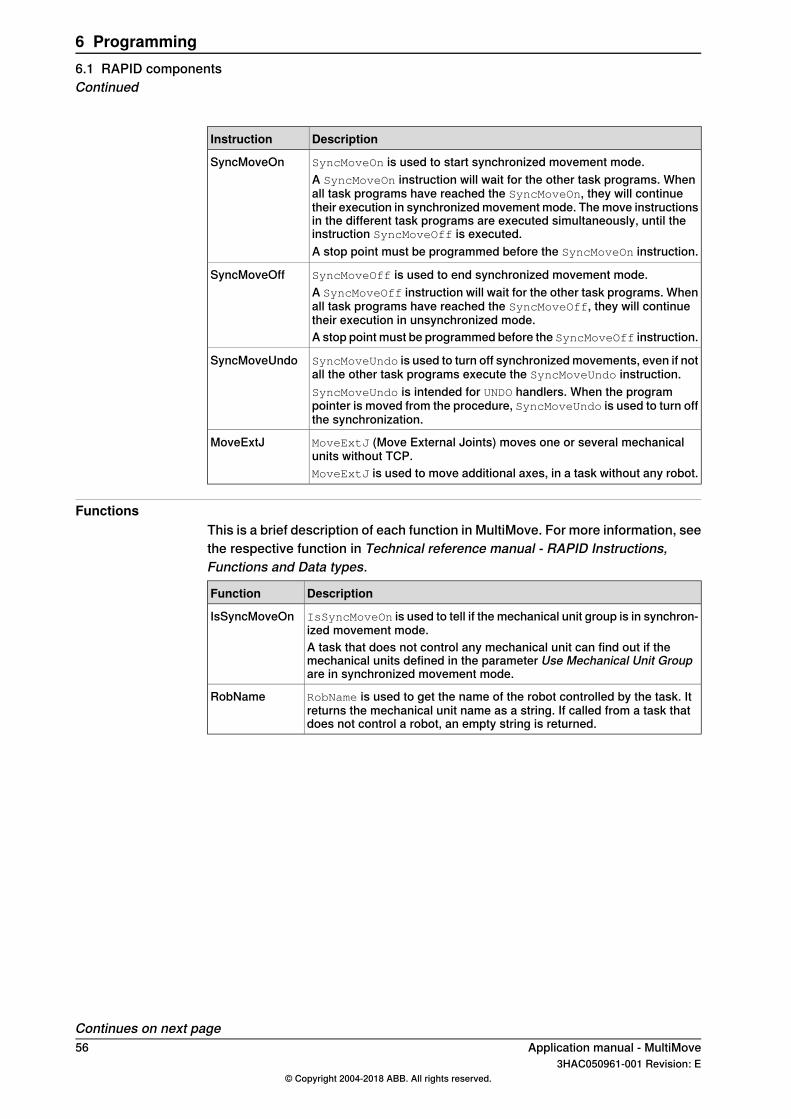
SyncMoveOn is used to start synchronized movement mode.SyncMoveOnA SyncMoveOn instruction will wait for the other task programs. Whenall task programs have reached the SyncMoveOn, they will continuetheir execution in synchronized movement mode. The move instructionsin the different task programs are executed simultaneously, until theinstruction SyncMoveOff is executed.A stop point must be programmed before the SyncMoveOn instruction.
SyncMoveOff is used to end synchronized movement mode.SyncMoveOffA SyncMoveOff instruction will wait for the other task programs. Whenall task programs have reached the SyncMoveOff, they will continuetheir execution in unsynchronized mode.A stop point must be programmed before the SyncMoveOff instruction.
SyncMoveUndo is used to turn off synchronized movements, even if notall the other task programs execute the SyncMoveUndo instruction.
SyncMoveUndo
SyncMoveUndo is intended for UNDO handlers. When the programpointer is moved from the procedure, SyncMoveUndo is used to turn offthe synchronization.
MoveExtJ (Move External Joints) moves one or several mechanicalunits without TCP.
MoveExtJ
MoveExtJ is used to move additional axes, in a task without any robot.
FunctionsThis is a brief description of each function in MultiMove. For more information, seethe respective function in Technical reference manual - RAPID Instructions,Functions and Data types.
DescriptionFunction
IsSyncMoveOn is used to tell if the mechanical unit group is in synchron-ized movement mode.
IsSyncMoveOn
A task that does not control any mechanical unit can find out if themechanical units defined in the parameter Use Mechanical Unit Groupare in synchronized movement mode.
RobName is used to get the name of the robot controlled by the task. Itreturns the mechanical unit name as a string. If called from a task thatdoes not control a robot, an empty string is returned.
RobName
Continues on next page56 Application manual - MultiMove
3HAC050961-001 Revision: E© Copyright 2004-2018 ABB. All rights reserved.
6 Programming6.1 RAPID componentsContinued
Synchronizing argumentThis is a brief description of the arguments used by move instructions to facilitatethe synchronization between tasks. For more information, see any move instructionin Technical reference manual - RAPID Instructions, Functions and Data types.
DescriptionArgument
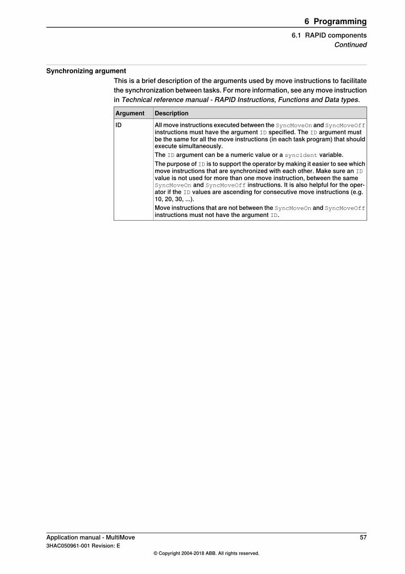
All move instructions executed between the SyncMoveOn and SyncMoveOffinstructions must have the argument ID specified. The ID argument mustbe the same for all the move instructions (in each task program) that shouldexecute simultaneously.
ID
The ID argument can be a numeric value or a syncident variable.The purpose of ID is to support the operator by making it easier to see whichmove instructions that are synchronized with each other. Make sure an IDvalue is not used for more than one move instruction, between the sameSyncMoveOn and SyncMoveOff instructions. It is also helpful for the oper-ator if the ID values are ascending for consecutive move instructions (e.g.10, 20, 30, ...).Move instructions that are not between the SyncMoveOn and SyncMoveOffinstructions must not have the argument ID.
Application manual - MultiMove 573HAC050961-001 Revision: E
© Copyright 2004-2018 ABB. All rights reserved.
6 Programming6.1 RAPID components
Continued
6.2 Tasks and programming techniques
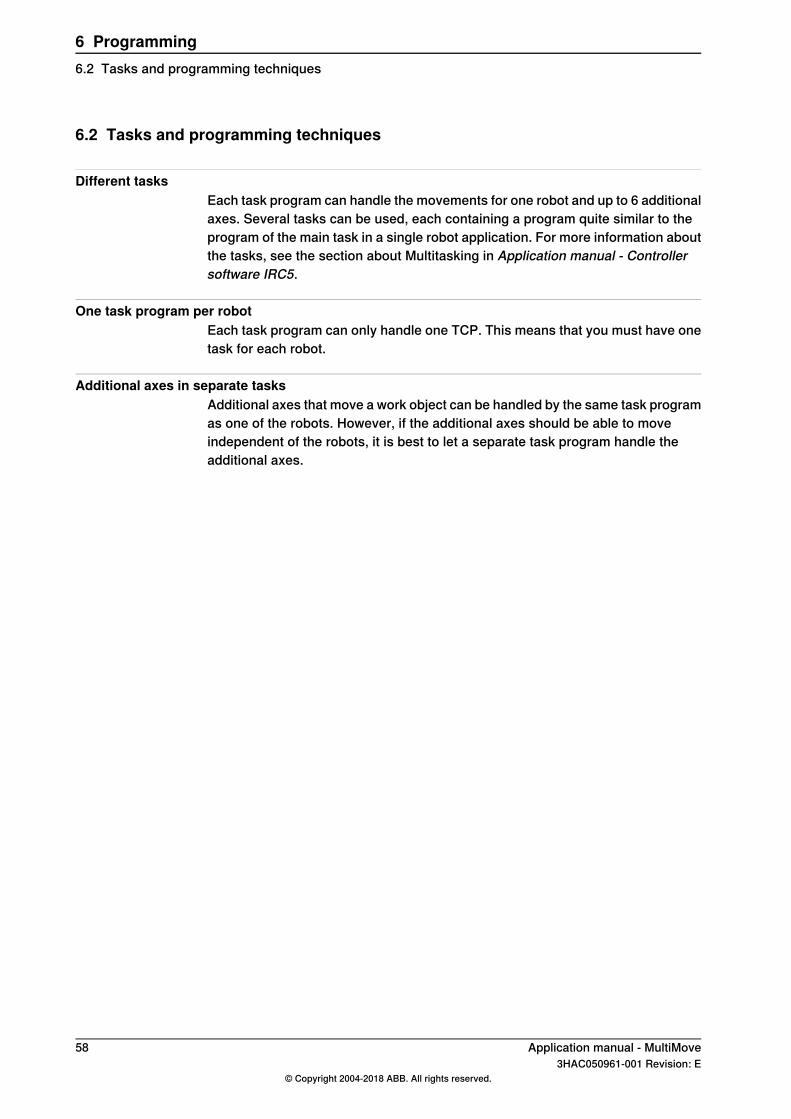
Different tasksEach task program can handle the movements for one robot and up to 6 additionalaxes. Several tasks can be used, each containing a program quite similar to theprogram of the main task in a single robot application. For more information aboutthe tasks, see the section about Multitasking in Application manual - Controllersoftware IRC5.
One task program per robotEach task program can only handle one TCP. This means that you must have onetask for each robot.
Additional axes in separate tasksAdditional axes that move a work object can be handled by the same task programas one of the robots. However, if the additional axes should be able to moveindependent of the robots, it is best to let a separate task program handle theadditional axes.
58 Application manual - MultiMove3HAC050961-001 Revision: E
© Copyright 2004-2018 ABB. All rights reserved.
6 Programming6.2 Tasks and programming techniques
6.3 Coordinated work objects
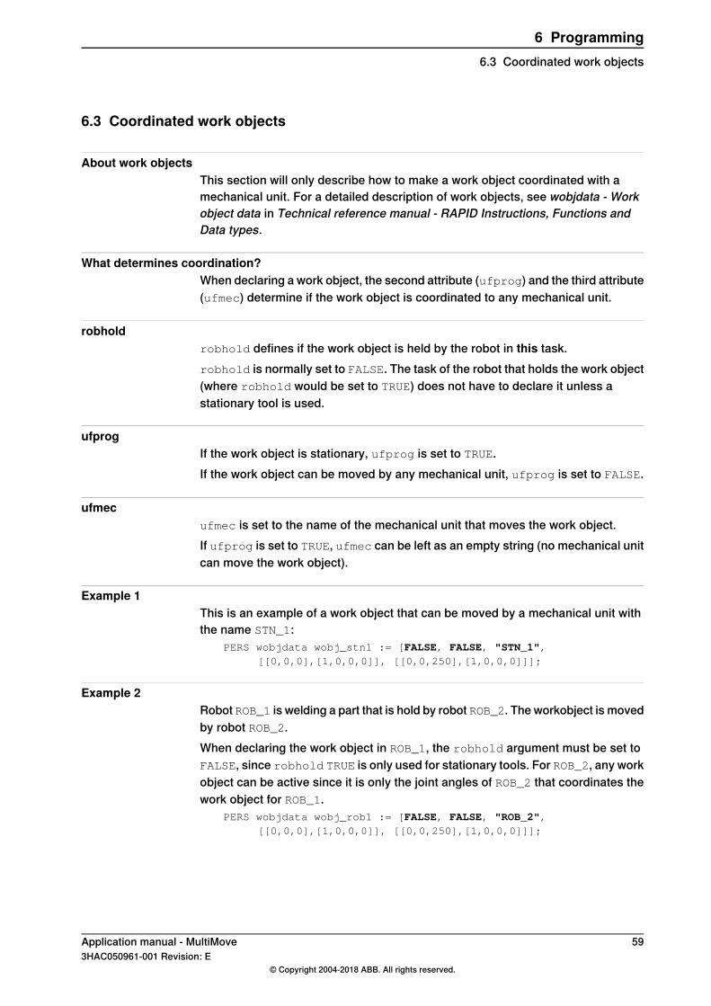
About work objectsThis section will only describe how to make a work object coordinated with amechanical unit. For a detailed description of work objects, see wobjdata - Workobject data in Technical reference manual - RAPID Instructions, Functions andData types.
What determines coordination?When declaring a work object, the second attribute (ufprog) and the third attribute(ufmec) determine if the work object is coordinated to any mechanical unit.
robholdrobhold defines if the work object is held by the robot in this task.robhold is normally set to FALSE. The task of the robot that holds the work object(where robhold would be set to TRUE) does not have to declare it unless astationary tool is used.
ufprogIf the work object is stationary, ufprog is set to TRUE.If the work object can be moved by any mechanical unit, ufprog is set to FALSE.
ufmecufmec is set to the name of the mechanical unit that moves the work object.If ufprog is set to TRUE, ufmec can be left as an empty string (no mechanical unitcan move the work object).
Example 1This is an example of a work object that can be moved by a mechanical unit withthe name STN_1:
PERS wobjdata wobj_stn1 := [FALSE, FALSE, "STN_1",[[0,0,0],[1,0,0,0]], [[0,0,250],[1,0,0,0]]];
Example 2Robot ROB_1 is welding a part that is hold by robot ROB_2. The workobject is movedby robot ROB_2.When declaring the work object in ROB_1, the robhold argument must be set toFALSE, since robhold TRUE is only used for stationary tools. For ROB_2, any workobject can be active since it is only the joint angles of ROB_2 that coordinates thework object for ROB_1.
PERS wobjdata wobj_rob1 := [FALSE, FALSE, "ROB_2",[[0,0,0],[1,0,0,0]], [[0,0,250],[1,0,0,0]]];
Application manual - MultiMove 593HAC050961-001 Revision: E
© Copyright 2004-2018 ABB. All rights reserved.
6 Programming6.3 Coordinated work objects
6.4 Independent movements
6.4.1 About independent movements
What is independent movementsIf the different task programs, and their robots, work independently, nosynchronization or coordination is needed. Each task program is then written asif it was the program for a single robot system.
Other dependencies than movementsSometimes, even if the movements do not need to be coordinated, the taskprograms can have dependencies. For example, if one robot leaves an object thata second robot will pick up, the first robot must finish with the object before thesecond robot can grab it.These interactions can be solved with:
• the instruction WaitSyncTask
• I/O signals• persistent variables together with WaitUntil
See the section about Multitasking in Application manual - Controller softwareIRC5.
60 Application manual - MultiMove3HAC050961-001 Revision: E
© Copyright 2004-2018 ABB. All rights reserved.
6 Programming6.4.1 About independent movements
6.4.2 Example "UnsyncArc" with independent movements
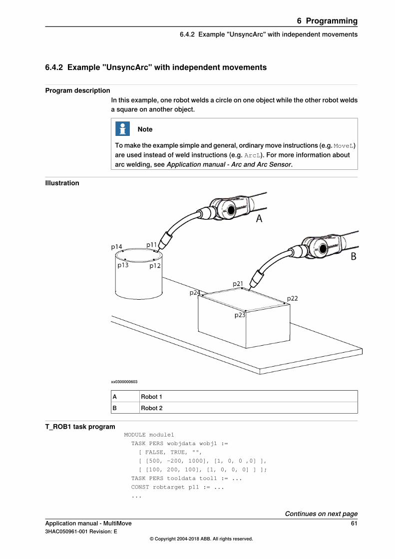
Program descriptionIn this example, one robot welds a circle on one object while the other robot weldsa square on another object.
Note
To make the example simple and general, ordinary move instructions (e.g. MoveL)are used instead of weld instructions (e.g. ArcL). For more information aboutarc welding, see Application manual - Arc and Arc Sensor.
Illustration
xx0300000603
Robot 1A
Robot 2B
T_ROB1 task programMODULE module1
TASK PERS wobjdata wobj1 :=
[ FALSE, TRUE, "",
[ [500, -200, 1000], [1, 0, 0 ,0] ],
[ [100, 200, 100], [1, 0, 0, 0] ] ];
TASK PERS tooldata tool1 := ...
CONST robtarget p11 := ...
...
Continues on next pageApplication manual - MultiMove 613HAC050961-001 Revision: E
© Copyright 2004-2018 ABB. All rights reserved.
6 Programming6.4.2 Example "UnsyncArc" with independent movements
CONST robtarget p14 := ...
PROC main()
...
IndependentMove;
...
ENDPROC
PROC IndependentMove()
MoveL p11, v500, fine, tool1\WObj:=wobj1;
MoveC p12, p13, v500, z10, tool1\WObj:=wobj1;
MoveC p14, p11, v500, fine, tool1\WObj:=wobj1;
ENDPROC
ENDMODULE
T_ROB2 task programMODULE module2
TASK PERS wobjdata wobj2 :=
[ FALSE, TRUE, "",
[ [500, -200, 1000], [1, 0, 0 ,0] ],
[ [100, 1200, 100], [1, 0, 0, 0] ] ];
TASK PERS tooldata tool2 := ...
CONST robtarget p21 := ...
...
CONST robtarget p24 := ...
PROC main()
...
IndependentMove;
...
ENDPROC
PROC IndependentMove()
MoveL p21, v500, fine, tool2\WObj:=wobj2;
MoveL p22, v500, z10, tool2\WObj:=wobj2;
MoveL p23, v500, z10, tool2\WObj:=wobj2;
MoveL p24, v500, z10, tool2\WObj:=wobj2;
MoveL p21, v500, fine, tool2\WObj:=wobj2;
ENDPROC
ENDMODULE
62 Application manual - MultiMove3HAC050961-001 Revision: E
© Copyright 2004-2018 ABB. All rights reserved.
6 Programming6.4.2 Example "UnsyncArc" with independent movementsContinued
6.5 Semi coordinated movements
6.5.1 About semi coordinated movements
What is semi coordinated movementsSeveral robots can work with the same work object, without synchronizedmovements, as long as the work object is not moving.A positioner can move the work object when the robots are not coordinated to it,and the robots can be coordinated to the work object when it is not moving.Switching between moving the object and coordinating the robots is called semicoordinated movements.
ImplementationSemi coordinated movements require some synchronization between the taskprograms (e.g. a WaitSyncTask instruction). The positioner must know when thework object can be moved, and the robots must know when they can work on thework object. However, it is not required that every move instruction is synchronized.
AdvantagesThe advantage is that each robot can work independently with the work object. Ifthe different robots perform very different assignments, this may save cycle timecompared to letting all the robot movements be synchronized.
Application manual - MultiMove 633HAC050961-001 Revision: E
© Copyright 2004-2018 ABB. All rights reserved.
6 Programming6.5.1 About semi coordinated movements
6.5.2 Example "SyncArc" with semi coordinated movements
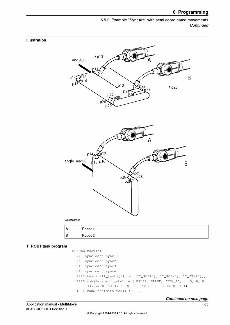
Program descriptionIn this example, we want to accomplish the welding of a small square and a longline on one side of the object. On another side of the object we want to make asquare and a circle.The positioner will first position the work object with the first side up, while therobots wait. Robot 1 will then weld a line at the same time as robot 2 welds a square.When the robots are done with the first welding operations, they wait while thepositioner turns the work object so the second side is upwards. Robot 1 will thenweld a circle at the same time as robot 2 welds a square.
WARNING
If the movement of the work object and the robot is not separated withWaitSyncTask and stop points the following can occur:
• the mechanical units controlled by the different tasks can collide• the robot is stepping backwards in the wrong direction• the movement or restart instruction can be blocked.
Note
To make the example simple and general, ordinary move instructions (e.g. MoveL)are used instead of weld instructions (e.g. ArcL). For more information aboutarc welding, see Application manual - Arc and Arc Sensor.
Continues on next page64 Application manual - MultiMove
3HAC050961-001 Revision: E© Copyright 2004-2018 ABB. All rights reserved.
6 Programming6.5.2 Example "SyncArc" with semi coordinated movements
Illustration
xx0300000596
Robot 1A
Robot 2B
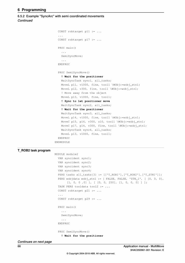
T_ROB1 task programMODULE module1
VAR syncident sync1;
VAR syncident sync2;
VAR syncident sync3;
VAR syncident sync4;
PERS tasks all_tasks{3} := [["T_ROB1"],["T_ROB2"],["T_STN1"]];
PERS wobjdata wobj_stn1 := [ FALSE, FALSE, "STN_1", [ [0, 0, 0],[1, 0, 0 ,0] ], [ [0, 0, 250], [1, 0, 0, 0] ] ];
TASK PERS tooldata tool1 := ...
Continues on next pageApplication manual - MultiMove 653HAC050961-001 Revision: E
© Copyright 2004-2018 ABB. All rights reserved.
6 Programming6.5.2 Example "SyncArc" with semi coordinated movements
Continued
CONST robtarget p11 := ...
...
CONST robtarget p17 := ...
PROC main()
...
SemiSyncMove;
...
ENDPROC
PROC SemiSyncMove()
! Wait for the positioner
WaitSyncTask sync1, all_tasks;
MoveL p11, v1000, fine, tool1 \WObj:=wobj_stn1;
MoveL p12, v300, fine, tool1 \WObj:=wobj_stn1;
! Move away from the object
MoveL p13, v1000, fine, tool1;
! Sync to let positioner move
WaitSyncTask sync2, all_tasks;
! Wait for the positioner
WaitSyncTask sync3, all_tasks;
MoveL p14, v1000, fine, tool1 \WObj:=wobj_stn1;
MoveC p15, p16, v300, z10, tool1 \WObj:=wobj_stn1;
MoveC p17, p14, v300, fine, tool1 \WObj:=wobj_stn1;
WaitSyncTask sync4, all_tasks;
MoveL p13, v1000, fine, tool1;
ENDPROC
ENDMODULE
T_ROB2 task programMODULE module2
VAR syncident sync1;
VAR syncident sync2;
VAR syncident sync3;
VAR syncident sync4;
PERS tasks all_tasks{3} := [["T_ROB1"],["T_ROB2"],["T_STN1"]];
PERS wobjdata wobj_stn1 := [ FALSE, FALSE, "STN_1", [ [0, 0, 0],[1, 0, 0 ,0] ], [ [0, 0, 250], [1, 0, 0, 0] ] ];
TASK PERS tooldata tool2 := ...
CONST robtarget p21 := ...
...
CONST robtarget p29 := ...
PROC main()
...
SemiSyncMove;
...
ENDPROC
PROC SemiSyncMove()
! Wait for the positioner
Continues on next page66 Application manual - MultiMove
3HAC050961-001 Revision: E© Copyright 2004-2018 ABB. All rights reserved.
6 Programming6.5.2 Example "SyncArc" with semi coordinated movementsContinued
WaitSyncTask sync1, all_tasks;
MoveL p21, v1000, fine, tool2 \WObj:=wobj_stn1;
MoveL p22, v300, z10, tool2 \WObj:=wobj_stn1;
MoveL p23, v300, z10, tool2 \WObj:=wobj_stn1;
MoveL p24, v300, z10, tool2 \WObj:=wobj_stn1;
MoveL p21, v300, fine, tool2 \WObj:=wobj_stn1;
! Move away from the object
MoveL p25, v1000, fine, tool2;
! Sync to let positioner move
WaitSyncTask sync2, all_tasks;
! Wait for the positioner
WaitSyncTask sync3, all_tasks;
MoveL p26, v1000, fine, tool2 \WObj:=wobj_stn1;
MoveL p27, v300, z10, tool2 \WObj:=wobj_stn1;
MoveL p28, v300, z10, tool2 \WObj:=wobj_stn1;
MoveL p29, v300, z10, tool2 \WObj:=wobj_stn1;
MoveL p26, v300, fine, tool2 \WObj:=wobj_stn1;
WaitSyncTask sync4, all_tasks;
MoveL p25, v1000, fine, tool2;
ENDPROC
ENDMODULE
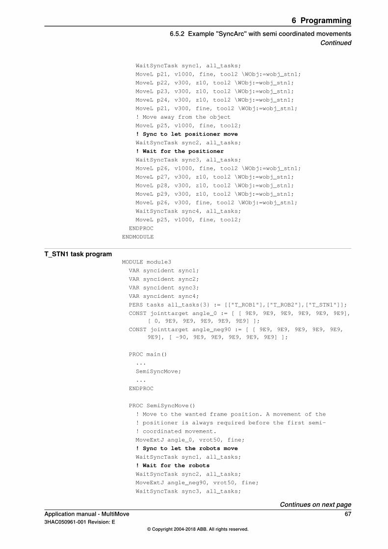
T_STN1 task programMODULE module3
VAR syncident sync1;
VAR syncident sync2;
VAR syncident sync3;
VAR syncident sync4;
PERS tasks all_tasks{3} := [["T_ROB1"],["T_ROB2"],["T_STN1"]];
CONST jointtarget angle_0 := [ [ 9E9, 9E9, 9E9, 9E9, 9E9, 9E9],[ 0, 9E9, 9E9, 9E9, 9E9, 9E9] ];
CONST jointtarget angle_neg90 := [ [ 9E9, 9E9, 9E9, 9E9, 9E9,9E9], [ -90, 9E9, 9E9, 9E9, 9E9, 9E9] ];
PROC main()
...
SemiSyncMove;
...
ENDPROC
PROC SemiSyncMove()
! Move to the wanted frame position. A movement of the
! positioner is always required before the first semi-
! coordinated movement.
MoveExtJ angle_0, vrot50, fine;
! Sync to let the robots move
WaitSyncTask sync1, all_tasks;
! Wait for the robots
WaitSyncTask sync2, all_tasks;
MoveExtJ angle_neg90, vrot50, fine;
WaitSyncTask sync3, all_tasks;
Continues on next pageApplication manual - MultiMove 673HAC050961-001 Revision: E
© Copyright 2004-2018 ABB. All rights reserved.
6 Programming6.5.2 Example "SyncArc" with semi coordinated movements
Continued
WaitSyncTask sync4, all_tasks;
ENDPROC
ENDMODULE
68 Application manual - MultiMove3HAC050961-001 Revision: E
© Copyright 2004-2018 ABB. All rights reserved.
6 Programming6.5.2 Example "SyncArc" with semi coordinated movementsContinued
6.5.3 Considerations and limitations when using semi coordinated movements
Stand still in known positionThe unit that controls the frame should stand still in a known position. To get aknown position, order a movement to a finepoint.
Activate taskThe unit that controls the frame should be activated in the task selection panel onthe FlexPendant (see Selecting tasks on page 53).
Finepoints and WaitSyncTask before and after semi coordinated movementThe semi coordinated movement shall be separated with finepoints andWaitSyncTask instructions before and after the movement.
Dealing with a cleared pathWhen any of the instructions listed below is used, the path is removed and theposition cannot be read by the other tasks.
• ActUnit
• DeactUnit
• ClearPath
• SyncMoveOn
• SyncMoveoff
• SyncMoveSuspend
• SyncMoveResume
After any of these instructions, order a movement to a wanted position for the unitthat controls the frame and insert a WaitSyncTask instruction before thesemicoordinated movement.Before changing to synchronized movement withSyncMoveOn orSyncMoveResume,the semi coordinated movement must be ended with a finepoint and aWaitSyncTask.
Example with semi coordinated and coordinated movement!Example with semicoordinated and synchronized movement
!Program example in task T_ROB1
PERS tasks task_list{2} := [ ["T_ROB1"], ["T_ROB2"] ];
PERS wobjdata rob2_obj:= [FALSE,FALSE,"ROB_2",[[0,0,0],[1,0,0,0]],[[155.241,-51.5938,57.6297],[0.493981,0.506191,-0.501597,0.49815]]];
VAR syncident sync0;
VAR syncident sync1;
VAR syncident sync2;
VAR syncident sync3;
VAR syncident sync4;
PROC main()
...
WaitSyncTask sync0, task_list;
Continues on next pageApplication manual - MultiMove 693HAC050961-001 Revision: E
© Copyright 2004-2018 ABB. All rights reserved.
6 Programming6.5.3 Considerations and limitations when using semi coordinated movements
MoveL p1_90, v100, fine, tcp1 \WObj:= rob2_obj;
WaitSyncTask sync1, task_list;
SyncMoveOn sync2, task_list;
MoveL p1_100 \ID:=10, v100, fine, tcp1 \WObj:= rob2_obj;
SyncMoveOff sync3;
!Wait until the movement has been finished in T_ROB2
WaitSyncTask sync3, task_list;
!Now a semicoordinated movement can be performed
MoveL p1_120, v100, z10, tcp1 \WObj:= rob2_obj;
MoveL p1_130, v100, fine, tcp1 \WObj:= rob2_obj;
WaitSyncTask sync4, task_list;
...
ENDPROC
!Program example in task T_ROB2
PERS tasks task_list{2} := [ ["T_ROB1"], ["T_ROB2"] ];
VAR syncident sync0;
VAR syncident sync1;
VAR syncident sync2;
VAR syncident sync3;
VAR syncident sync4;
PROC main()
...
MoveL p_fine, v1000, fine, tcp2;
WaitSyncTask sync0, task_list;
!Wait until the movement in T_ROB1 task is finished
WaitSyncTask sync1, task_list;
SyncMoveOn sync2, task_list;
MoveL p2_100 \ID:=10, v100, fine, tcp2;
SyncMoveOff sync3;
!The path has been removed at SyncMoveOff
!Perform a movement to wanted position for the object to
!make the position available for other tasks
MoveL p2_100, v100, fine, tcp2;
WaitSyncTask sync3, task_list;
WaitSyncTask sync4, task_list;
MoveL p2_110, v100, z10, tcp2;
...
ENDPROC
When switching between semicoordinated to synchronized movement, aWaitSyncTask is needed (when using identity sync1).When switching between synchronized to semicoordinated movement, the taskthat move the work object (rob2_obj) needs to move to the desired position. Afterthat a WaitSyncTask is needed (identity sync3) before the semicoordinatedmovement can be performed.
70 Application manual - MultiMove3HAC050961-001 Revision: E
© Copyright 2004-2018 ABB. All rights reserved.
6 Programming6.5.3 Considerations and limitations when using semi coordinated movementsContinued
6.6 Coordinated synchronized movements
6.6.1 About coordinated synchronized movements
What is coordinated synchronized movementsSeveral robots can work with the same moving work object.The positioner or robot that holds the work object and the robots that work withthe work object must have synchronized movements. This means that the RAPIDtask programs, that handle one mechanical unit each, execute their moveinstructions simultaneously.
ImplementationThe synchronized movement mode is started by executing a SyncMoveOn
instruction in each task program. The synchronized movement mode is ended byexecuting a SyncMoveOff instruction in each task program. The number ofexecuted move instruction between SyncMoveOn and SyncMoveOff has to be thesame for all task programs.
AdvantagesCoordinated synchronized movements usually save cycle time since the robotsdo not have to wait while the work object is being moved. It also allows robots tocooperate in ways that would otherwise be difficult or impossible to achieve.
LimitationsCoordinated synchronized movements can only be used if you have the RobotWareoption MultiMove Coordinated.
Application manual - MultiMove 713HAC050961-001 Revision: E
© Copyright 2004-2018 ABB. All rights reserved.
6 Programming6.6.1 About coordinated synchronized movements
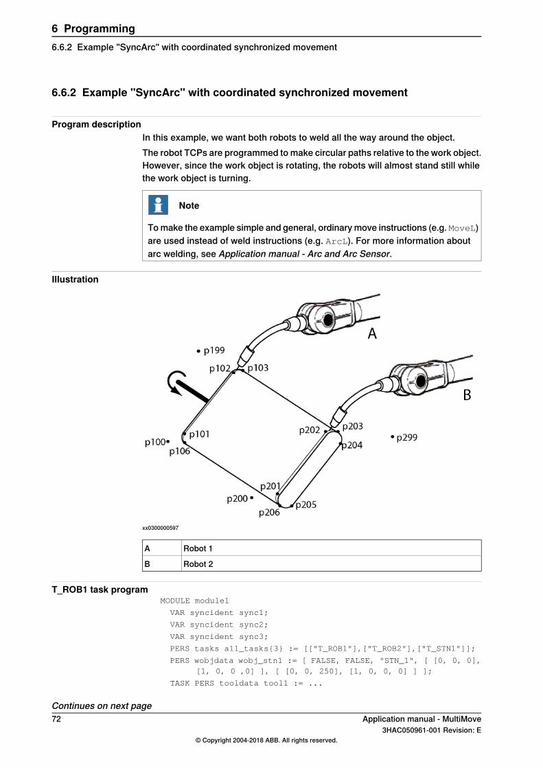
6.6.2 Example "SyncArc" with coordinated synchronized movement
Program descriptionIn this example, we want both robots to weld all the way around the object.The robot TCPs are programmed to make circular paths relative to the work object.However, since the work object is rotating, the robots will almost stand still whilethe work object is turning.
Note
To make the example simple and general, ordinary move instructions (e.g. MoveL)are used instead of weld instructions (e.g. ArcL). For more information aboutarc welding, see Application manual - Arc and Arc Sensor.
Illustration
xx0300000597
Robot 1A
Robot 2B
T_ROB1 task programMODULE module1
VAR syncident sync1;
VAR syncident sync2;
VAR syncident sync3;
PERS tasks all_tasks{3} := [["T_ROB1"],["T_ROB2"],["T_STN1"]];
PERS wobjdata wobj_stn1 := [ FALSE, FALSE, "STN_1", [ [0, 0, 0],[1, 0, 0 ,0] ], [ [0, 0, 250], [1, 0, 0, 0] ] ];
TASK PERS tooldata tool1 := ...
Continues on next page72 Application manual - MultiMove
3HAC050961-001 Revision: E© Copyright 2004-2018 ABB. All rights reserved.
6 Programming6.6.2 Example "SyncArc" with coordinated synchronized movement
CONST robtarget p100 := ...
...
CONST robtarget p199 := ...
PROC main()
...
SyncMove;
...
ENDPROC
PROC SyncMove()
MoveJ p100, v1000, z50, tool1;
WaitSyncTask sync1, all_tasks;
MoveL p101, v500, fine, tool1 \WObj:=wobj_stn1;
SyncMoveOn sync2, all_tasks;
MoveL p102\ID:=10, v300, z10, tool1 \WObj:=wobj_stn1;
MoveC p103, p104\ID:=20, v300, z10, tool1 \WObj:=wobj_stn1;
MoveL p105\ID:=30, v300, z10, tool1 \WObj:=wobj_stn1;
MoveC p106, p101\ID:=40, v300, fine, tool1 \WObj:=wobj_stn1;
SyncMoveOff sync3;
MoveL p199, v1000, fine, tool1;
UNDO
SyncMoveUndo;
ENDPROC
ENDMODULE
T_ROB2 task programMODULE module2
VAR syncident sync1;
VAR syncident sync2;
VAR syncident sync3;
PERS tasks all_tasks{3} := [["T_ROB1"],["T_ROB2"],["T_STN1"]];
PERS wobjdata wobj_stn1 := [ FALSE, FALSE, "STN_1", [ [0, 0, 0],[1, 0, 0 ,0] ], [ [0, 0, 250], [1, 0, 0, 0] ] ];
TASK PERS tooldata tool2 := ...
CONST robtarget p200 := ...
...
CONST robtarget p299 := ...
PROC main()
...
SyncMove;
...
ENDPROC
PROC SyncMove()
MoveJ p200, v1000, z50, tool2;
WaitSyncTask sync1, all_tasks;
MoveL p201, v500, fine, tool2 \WObj:=wobj_stn1;
SyncMoveOn sync2, all_tasks;
MoveL p202\ID:=10, v300, z10, tool2 \WObj:=wobj_stn1;
Continues on next pageApplication manual - MultiMove 733HAC050961-001 Revision: E
© Copyright 2004-2018 ABB. All rights reserved.
6 Programming6.6.2 Example "SyncArc" with coordinated synchronized movement
Continued
MoveC p203, p204\ID:=20, v300, z10, tool2 \WObj:=wobj_stn1;
MoveL p205\ID:=30, v300, z10, tool2 \WObj:=wobj_stn1;
MoveC p206, p201\ID:=40, v300, fine, tool2 \WObj:=wobj_stn1;
SyncMoveOff sync3;
MoveL p299, v1000, fine, tool2;
UNDO
SyncMoveUndo;
ENDPROC
ENDMODULE
T_STN1 task programMODULE module3
VAR syncident sync1;
VAR syncident sync2;
VAR syncident sync3;
PERS tasks all_tasks{3} := [["T_ROB1"],["T_ROB2"],["T_STN1"]];
CONST jointtarget angle_neg20 := [ [ 9E9, 9E9, 9E9, 9E9, 9E9,9E9], [ -20, 9E9, 9E9, 9E9, 9E9, 9E9] ];
...
CONST jointtarget angle_340 := [ [ 9E9, 9E9, 9E9, 9E9, 9E9, 9E9],[ 340, 9E9, 9E9, 9E9, 9E9, 9E9] ];
PROC main()
...
SyncMove;
...
ENDPROC
PROC SyncMove()
MoveExtJ angle_neg20, vrot50, fine;
WaitSyncTask sync1, all_tasks;
! Wait for the robots
SyncMoveOn sync2, all_tasks;
MoveExtJ angle_20\ID:=10, vrot100, z10;
MoveExtJ angle_160\ID:=20, vrot100, z10;
MoveExtJ angle_200\ID:=30, vrot100, z10;
MoveExtJ angle_340\ID:=40, vrot100, fine;
SyncMoveOff sync3;
UNDO
SyncMoveUndo;
ENDPROC
ENDMODULE
74 Application manual - MultiMove3HAC050961-001 Revision: E
© Copyright 2004-2018 ABB. All rights reserved.
6 Programming6.6.2 Example "SyncArc" with coordinated synchronized movementContinued
6.7 Program execution
6.7.1 Corner zones
Corner zones and WaitSyncTaskCorner zones can be used when synchronizing several task programs withWaitSyncTask.
Corner zones and synchronized movementsStop points must be used both before starting the synchronized movements withSyncMoveOn and before ending it with SyncMoveOff. All other move instructionsbetween SyncMoveOn and SyncMoveOff can, on the other hand, use corner zones.
Dependences between synchronized instructionsIn synchronized movements mode, all or none of the simultaneous moveinstructions must be programmed with corner zones. This means that the moveinstructions with the same ID must either all have corner zones, or all have stoppoints. If a move instruction with a corner zone and a move instruction with a stoppoint are synchronously executed in their respective task program, an error willoccur.Synchronously executed move instructions can have corner zones of differentsizes (e.g. one use z10 and one use z50).
Corner zones converted to stop pointsA corner zone will become a stop point if the task program has to wait for anothertask program. This can happen if WaitSyncTask is executed in a corner zone, butone task program reaches this instruction later than the others.
Example with corner zonesGiven the RAPID code below, the following will happen:
• If robot1 reaches p11 at approximately the same time as robot2 reaches p21,both robots will be synchronized in corner zones (p11 and p21).
• If robot1 reaches p11 before robot2 reaches p21, p11 will become a stoppoint.
• If robot2 reaches p21 before robot1 reaches p11, p21 will become a stoppoint.
Note that both move instructions with corner zones and move instructions withstop points can be used in each task. You just have to make sure that theinstructions with the same ID in both task programs are of the same type. Theinstructions before SyncMoveOn and SyncMoveOff must have stop points.
Part of T_ROB1 task program:MoveL p11, v500, z50, tool1;
WaitSyncTask sync1, all_tasks;
MoveL p12, v500, fine, tool1;
SyncMoveOn sync2, all_tasks;
Continues on next pageApplication manual - MultiMove 753HAC050961-001 Revision: E
© Copyright 2004-2018 ABB. All rights reserved.
6 Programming6.7.1 Corner zones
MoveL p13\ID:=10, v500, z50, tool1 \WObj:=wobj_stn1;
MoveL p14\ID:=20, v500, fine, tool1 \WObj:=wobj_stn1;
SyncMoveOff sync3;
MoveL p15, v500, fine, tool1;
Part of T_ROB2 task program:MoveL p21, v500, z50, tool2;
WaitSyncTask sync1, all_tasks;
MoveL p22, v500, fine, tool2;
SyncMoveOn sync2, all_tasks;
MoveL p23\ID:=10, v500, z10, tool2 \WObj:=wobj_stn1;
MoveL p24\ID:=20, v500, fine, tool2 \WObj:=wobj_stn1;
SyncMoveOff sync3;
MoveL p25, v500, fine, tool2;
76 Application manual - MultiMove3HAC050961-001 Revision: E
© Copyright 2004-2018 ABB. All rights reserved.
6 Programming6.7.1 Corner zonesContinued
6.7.2 Synchronization behavior
Synchronization pointWhen one task program reaches a synchronization point, it will wait until all taskprograms have reached the same synchronization point.Synchronization points are:
• all WaitSyncTask instructions• all SyncMoveOn instructions• all SyncMoveOff instructions• all move instructions between SyncMoveOn and SyncMoveOff
When one task program reaches a WaitSyncTask, SyncMoveOn or SyncMoveOffinstruction, it will wait until all task programs have reached the instruction with thesame syncident variable.All move instructions between SyncMoveOn and SyncMoveOff must use theargument ID. When a task program reaches such a move instruction, it will waituntil all task programs have reached the move instruction with the ID argumentset to the same value.
Other instructions than movementsAll synchronized task programs must execute the same number of move instructionsbetween the SyncMoveOn and SyncMoveOff instructions. This does not affectfunctions or other instructions than move instructions. It is possible to have anynumber of functions and instructions that are not move instructions.
ExampleIn this example both task programs execute two move instructions, but one of thetasks executes other instructions and functions.Robot 2 will wait and not move to p21 until robot 1 starts to move towards p11.Since SyncMoveOff is a synchronization point, both tasks will wait for di1 tobecome 1 before executing SyncMoveOff.
Part of T_ROB2 task program:SyncMoveOn sync1, all_tasks;
time := CTime();
Write log, "Synchronization started "\NoNewLine;
Write log, time;
MoveL p11\ID:=10, v500, fine, tool1 \WObj:=wobj_stn1;
Set do1;
MoveC p12, p13\ID:=20, v500, fine, tool1 \WObj:=wobj_stn1;
WaitDI di1, 1;
SyncMoveOff sync2;
Part of T_ROB2 task program:SyncMoveOn sync1, all_tasks;
MoveJ p21\ID:=10, v500, fine, tool2 \WObj:=wobj_stn1;
MoveL p22\ID:=20, v500, fine, tool2 \WObj:=wobj_stn1;
SyncMoveOff sync2;
Application manual - MultiMove 773HAC050961-001 Revision: E
© Copyright 2004-2018 ABB. All rights reserved.
6 Programming6.7.2 Synchronization behavior
6.7.3 Dummy instructions
About dummy instructionsThe same number of move instructions must be executed between SyncMoveOn
and SyncMoveOff in all task programs. If a move instruction is only executedunder certain circumstances, the number of move instructions may differ from theother task programs. This can be solved by adding a move instruction to the pointwhere the robot already is (a dummy instruction) for the case where the originalmove instruction is not executed.
Example with dummy move instructionsIn this example, the task program needs to execute two move instructions if di1 isset to 1. If di1 is 0, two move instructions are executed that move the robot to theposition where it already is (dummy instructions).
Part of a task programSyncMoveOn sync1, all_tasks;
MoveL p1\ID:=10, v500, fine, tool1 \WObj:=wobj_stn1;
IF di1=1 THEN
! Instructions executed under certain conditions
MoveL p2\ID:=20, v500, fine, tool1 \WObj:=wobj_stn1;
MoveL p1\ID:=30, v500, fine, tool1 \WObj:=wobj_stn1;
ELSE
! Add dummy move instructions
MoveL p1\ID:=20, v500, fine, tool1 \WObj:=wobj_stn1;
MoveL p1\ID:=30, v500, fine, tool1 \WObj:=wobj_stn1;
ENDIF
SyncMoveOff sync2;
78 Application manual - MultiMove3HAC050961-001 Revision: E
© Copyright 2004-2018 ABB. All rights reserved.
6 Programming6.7.3 Dummy instructions
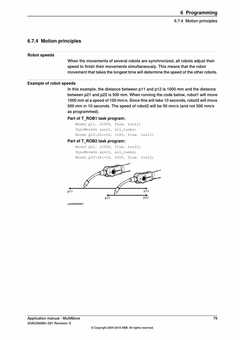
6.7.4 Motion principles
Robot speedsWhen the movements of several robots are synchronized, all robots adjust theirspeed to finish their movements simultaneously. This means that the robotmovement that takes the longest time will determine the speed of the other robots.
Example of robot speedsIn this example, the distance between p11 and p12 is 1000 mm and the distancebetween p21 and p22 is 500 mm. When running the code below, robot1 will move1000 mm at a speed of 100 mm/s. Since this will take 10 seconds, robot2 will move500 mm in 10 seconds. The speed of robot2 will be 50 mm/s (and not 500 mm/sas programmed).Part of T_ROB1 task program:
MoveJ p11, v1000, fine, tool1;
SyncMoveOn sync1, all_tasks;
MoveL p12\ID:=10, v100, fine, tool1;
Part of T_ROB2 task program:MoveJ p21, v1000, fine, tool2;
SyncMoveOn sync1, all_tasks;
MoveL p22\ID:=10, v500, fine, tool2;
xx0400000907
Application manual - MultiMove 793HAC050961-001 Revision: E
© Copyright 2004-2018 ABB. All rights reserved.
6 Programming6.7.4 Motion principles
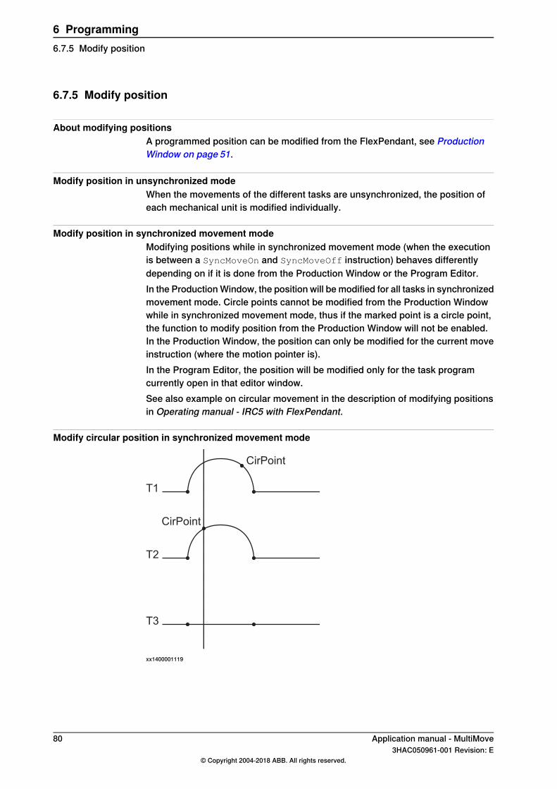
6.7.5 Modify position
About modifying positionsA programmed position can be modified from the FlexPendant, see ProductionWindow on page 51.
Modify position in unsynchronized modeWhen the movements of the different tasks are unsynchronized, the position ofeach mechanical unit is modified individually.
Modify position in synchronized movement modeModifying positions while in synchronized movement mode (when the executionis between a SyncMoveOn and SyncMoveOff instruction) behaves differentlydepending on if it is done from the Production Window or the Program Editor.In the Production Window, the position will be modified for all tasks in synchronizedmovement mode. Circle points cannot be modified from the Production Windowwhile in synchronized movement mode, thus if the marked point is a circle point,the function to modify position from the Production Window will not be enabled.In the Production Window, the position can only be modified for the current moveinstruction (where the motion pointer is).In the Program Editor, the position will be modified only for the task programcurrently open in that editor window.See also example on circular movement in the description of modifying positionsin Operating manual - IRC5 with FlexPendant.
Modify circular position in synchronized movement mode
T1
T2
CirPoint
CirPoint
T3
xx1400001119
80 Application manual - MultiMove3HAC050961-001 Revision: E
© Copyright 2004-2018 ABB. All rights reserved.
6 Programming6.7.5 Modify position
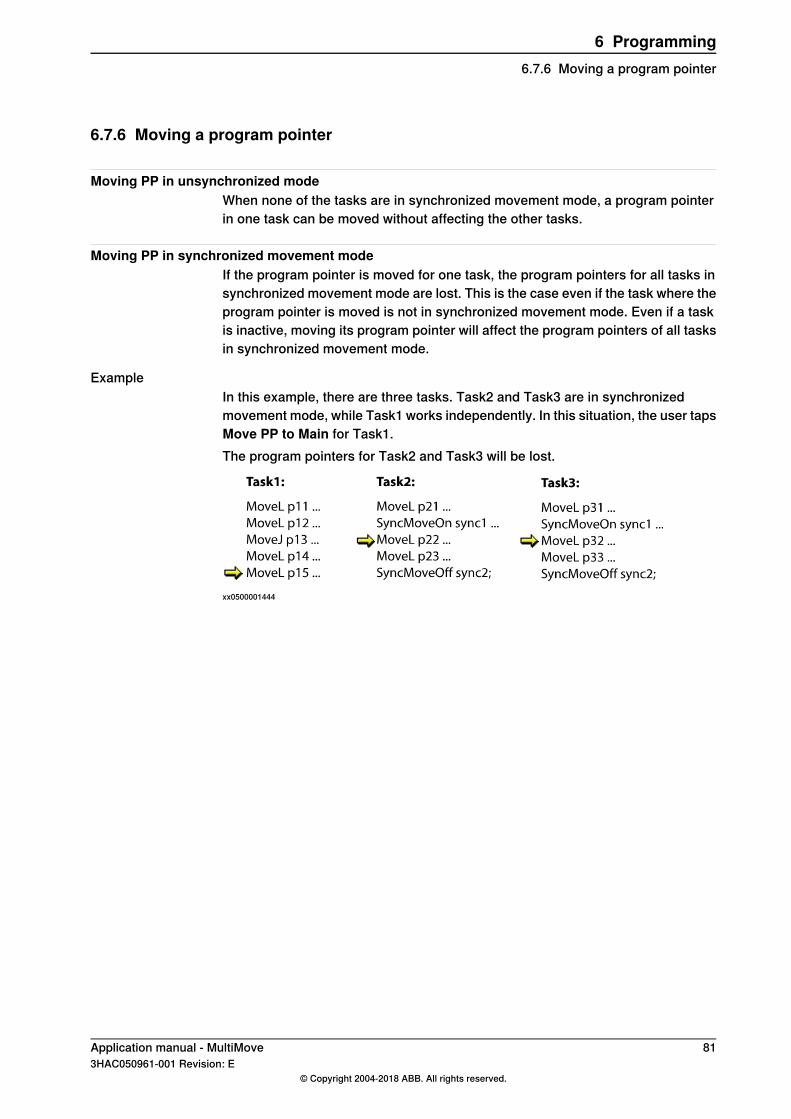
6.7.6 Moving a program pointer
Moving PP in unsynchronized modeWhen none of the tasks are in synchronized movement mode, a program pointerin one task can be moved without affecting the other tasks.
Moving PP in synchronized movement modeIf the program pointer is moved for one task, the program pointers for all tasks insynchronized movement mode are lost. This is the case even if the task where theprogram pointer is moved is not in synchronized movement mode. Even if a taskis inactive, moving its program pointer will affect the program pointers of all tasksin synchronized movement mode.
ExampleIn this example, there are three tasks. Task2 and Task3 are in synchronizedmovement mode, while Task1 works independently. In this situation, the user tapsMove PP to Main for Task1.The program pointers for Task2 and Task3 will be lost.
xx0500001444
Application manual - MultiMove 813HAC050961-001 Revision: E
© Copyright 2004-2018 ABB. All rights reserved.
6 Programming6.7.6 Moving a program pointer
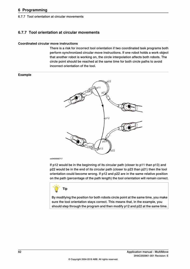
6.7.7 Tool orientation at circular movements
Coordinated circular move instructionsThere is a risk for incorrect tool orientation if two coordinated task programs bothperform synchronized circular move instructions. If one robot holds a work objectthat another robot is working on, the circle interpolation affects both robots. Thecircle point should be reached at the same time for both circle paths to avoidincorrect orientation of the tool.
Example
xx0400000717
If p12 would be in the beginning of its circular path (closer to p11 than p13) andp22 would be in the end of its circular path (closer to p23 than p21) then the toolorientation could become wrong. If p12 and p22 are in the same relative positionon the path (percentage of the path length) the tool orientation will remain correct.
Tip
By modifying the position for both robots circle point at the same time, you makesure the tool orientation stays correct. This means that, in the example, youshould step through the program and then modify p12 and p22 at the same time.
82 Application manual - MultiMove3HAC050961-001 Revision: E
© Copyright 2004-2018 ABB. All rights reserved.
6 Programming6.7.7 Tool orientation at circular movements
6.7.8 Applications affected by MultiMove
Collision DetectionIf collision is detected for one robot, all robots are stopped. Even if the robots arerun individually, all robots behave as if it had collided.One reason for this behavior is that when a collision is detected, there is a big riskthat it was two robots that collided. Another reason is that if one robot stops andanother continues, this might cause another collision.
World ZonesA world zone declared in one task program is only valid for the mechanical unitsthat belong to that task. For a world zone to affect all mechanical units, it must bedeclared in all task programs.
Application manual - MultiMove 833HAC050961-001 Revision: E
© Copyright 2004-2018 ABB. All rights reserved.
6 Programming6.7.8 Applications affected by MultiMove
6.8 Programming recommendations
6.8.1 Programming recommendations
Declare syncident globally in taskBy declaring all variables of the data type syncident globally in the task program,there is no risk of having two syncident with the same name in the same taskprogram.
Do not reuse syncidentA syncident variable is used as an argument for all WaitSyncTask, SyncMoveOnand SyncMoveOff instructions, so that the operator can distinguish whichinstructions are executed simultaneously in the different task programs. If onesyncident variable would be used as argument for more than one instruction pertask, that instruction would no longer be uniquely identified. To make sure yourprogram code is understandable, never reuse a syncident variable.
Declaring tools, work objects and payloadsDeclaring a variable as TASK PERS will make it persistent in the task program, butnot shared between tasks. By declaring tools, work objects and payloads as taskpersistent, you do not have to keep track of whether the variable name is used inother tasks. If tools, work objects and payloads are declared as TASK PERS, thenames do not have to be changed if the program is copied or mirrored to anothertask.A work object that is used by several task programs is preferably declared as PERS.A tool can be declared as PERS if a background task needs to read the robotposition.
Changing a PERSA globally declared PERS will keep its value even if a new declaration of the samePERS is loaded. The value of the PERS that was first loaded will be preserved aslong as there is any reference to that PERS.If you want to replace all the task programs with new programs where the valuesof the PERS is different, remove all task programs first and then load all the newtask programs. That way the old value of the PERSwill be lost when all declarationsof it are removed.Changing the value of a PERS from the Data Variable view on the FlexPendant andsaving the program, will update the PERS in a correct way.
Use SyncMoveUndoAlways use an UNDO handler with a SyncMoveUndo instruction in any procedurethat has synchronized movements (i.e. that has a SyncMoveOn instruction).After a SyncMoveOn instruction, the movements in the task program aresynchronized with movements in other task programs. If the program pointer isthen manually moved before the SyncMoveOff instruction is executed, the
Continues on next page84 Application manual - MultiMove
3HAC050961-001 Revision: E© Copyright 2004-2018 ABB. All rights reserved.
6 Programming6.8.1 Programming recommendations
movements will still be synchronized. This can be avoided by having an UNDO
handler that includes a SyncMoveUndo instruction.When the program pointer is manually moved out of a procedure, the UNDO handlerfor that procedure is called. The SyncMoveUndo instruction will end thesynchronization if the movements currently are synchronized. If the movementsare not synchronized when the program pointer is moved, SyncMoveUndo will donothing. It is, in other words, never any disadvantage in using SyncMoveUndo, butvery useful if the program pointer is moved.For more information about UNDO handlers, see Technical reference manual -RAPID Overview.
Coordinating against a work objectCoordinating against a work object moved by a mechanical unit in another taskcan be done in two ways:
• All move instructions coordinated with the work object must be executedwhen the work object is standing still. See Semi coordinated movements onpage 63.
• The robot that is coordinated with the work object and the mechanical unitthat moves the work object must be in synchronized movement mode. SeeCoordinated synchronized movements on page 71.
It is not possible to coordinate against a moving work object, controlled fromanother task, without being in synchronized movement mode.
Common work areaIf two robots use the same work area, without being in synchronized movementmode, precautions must be taken to avoid collisions. Make sure that only one ofthe robots is in the common area at a time by using one of the following:
• WaitSyncTask• World Zones• I/O signal
Application manual - MultiMove 853HAC050961-001 Revision: E
© Copyright 2004-2018 ABB. All rights reserved.
6 Programming6.8.1 Programming recommendations
Continued

This page is intentionally left blank
7 RAPID error recovery7.1 Error recovery for MultiMove
Error in unsynchronized modeIf an error occurs during unsynchronized mode, it is handled just like in a singlerobot system. No other task program is affected by the error.
Error in synchronized movement modeIf an error occurs during synchronized movement mode, the task program with theerror will stop with an error code, just like in a single robot system. Because of thesynchronization, the other tasks will not continue to move. When the error hasbeen resolved the movement can continue in all task programs.
Application manual - MultiMove 873HAC050961-001 Revision: E
© Copyright 2004-2018 ABB. All rights reserved.
7 RAPID error recovery7.1 Error recovery for MultiMove
7.2 Simple error recovery example
About this exampleIn this example, a division with zero causes an error during synchronized movementmode. Since the error handler can resolve the error without any motion instructions,the error handler does not have to consider the synchronization. The synchronizedmovement mode is active the whole time and the second move instruction is startedfor both robots as soon as the error handler has finished. If no other error canoccur, the T_HANDLEROB task program does not need to have an error handler.
T_PROCROB task program...
SyncMoveOn, sync1, motion_tasks;
MoveL p101\ID:=10, v100, z10, gun2 \WObj:=wobj_handlerob;
a:=3;
b:=0;
c:=a/b;
MoveL p102\ID:=20, v100, fine, gun2 \WObj:=wobj_handlerob;
SyncMoveOff sync2;
...
ERROR
IF ERRNO = ERR_DIVZERO THEN
b:=1;
RETRY;
ENDIF
T_HANDLEROB task program...
SyncMoveOn, sync1, motion_tasks;
MoveL p201\ID:=10, v100, z10, grip1;
MoveL p202\ID:=20, v100, fine, grip1;
SyncMoveOff sync2;
...
88 Application manual - MultiMove3HAC050961-001 Revision: E
© Copyright 2004-2018 ABB. All rights reserved.
7 RAPID error recovery7.2 Simple error recovery example
7.3 Asynchronously raised errors
What is an asynchronously raised errorAsynchronously raised errors can be raised by another instruction than theinstruction where the program pointer is. This means that an asynchronous errorcan be raised while the robot is in the middle of a path movement. For moreinformation about asynchronously raised errors, see Technical reference manualmanual - RAPID kernel.The technique with asynchronously raised errors allows a failing instruction in onetask program to raise an error in all other task programs with synchronizedmovements.
How to raise an asynchronous errorThe instruction ProcerrRecovery will raise the error ERR_PATH_STOP and stopthe movement for all task programs with synchronized movements.Asynchronous errors can also be raised by process instructions (e.g. ArcL). Thesecan raise one error code (describing the cause of the error) in the task programwhere the error occurred, and raise the error ERR_PATH_STOP in the other taskprograms with synchronized movements.
The task programs without errorsIf two task programs run synchronized move instructions and one of them raisean asynchronous error, the movements will stop for both tasks. The task programwhere nothing went wrong will then get the error ERR_PATH_STOP. This error mustbe handled by an error handler. The error handler can handle ERR_PATH_STOP byjust waiting for the other task to solve its problems and then resume the movements.By using the instruction StartMoveRetry, the execution will continue when alltasks reach this instruction.
Independent movements in the error handlerIf the error handler in one task program needs to execute a move instruction, thesynchronization must be suspended first.The synchronization is automatically suspended by the StorePath instruction.All tasks with synchronized movements must execute a StorePath instructionbefore the synchronization is turned off and the execution can continue.The instruction RestoPath will restore synchronization to the mode it had beforeStorePath. All task programs with synchronized movements must execute theRestoPath instruction in their error handlers before the synchronization is resumedand the execution can continue.Between the instructions StorePath and RestoPath, the failing task programcan move independently to solve its problem. Since RestoPath works as asynchronization point, the other task programs will wait at this point until theproblem has been resolved.If the task program is not in synchronized movements mode, StorePath andRestoPath act just like they do in a single robot system. This means that the same
Continues on next pageApplication manual - MultiMove 893HAC050961-001 Revision: E
© Copyright 2004-2018 ABB. All rights reserved.
7 RAPID error recovery7.3 Asynchronously raised errors
error handler code can handle errors that occur both in synchronized movementsmode and unsynchronized mode.StorePath and RestoPath require the option Path Recovery. For more informationabout StorePath and RestoPath, see Application manual - Controller softwareIRC5.
90 Application manual - MultiMove3HAC050961-001 Revision: E
© Copyright 2004-2018 ABB. All rights reserved.
7 RAPID error recovery7.3 Asynchronously raised errorsContinued
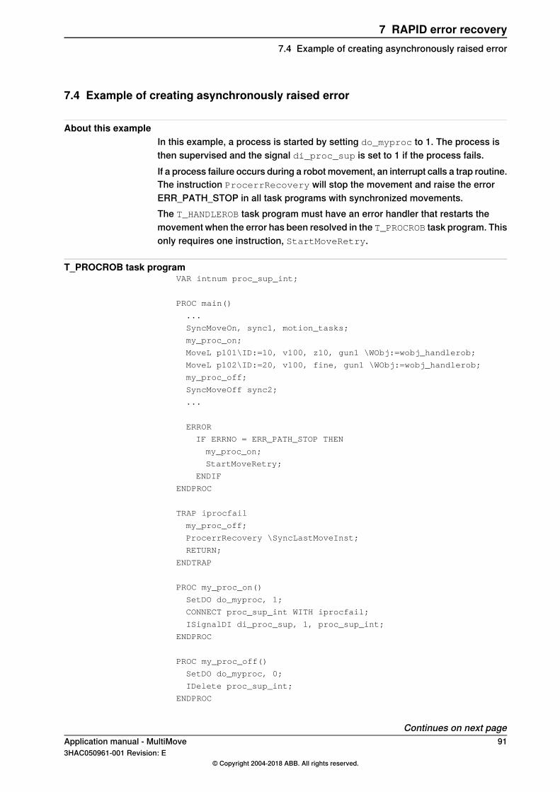
7.4 Example of creating asynchronously raised error
About this exampleIn this example, a process is started by setting do_myproc to 1. The process isthen supervised and the signal di_proc_sup is set to 1 if the process fails.If a process failure occurs during a robot movement, an interrupt calls a trap routine.The instruction ProcerrRecovery will stop the movement and raise the errorERR_PATH_STOP in all task programs with synchronized movements.The T_HANDLEROB task program must have an error handler that restarts themovement when the error has been resolved in the T_PROCROB task program. Thisonly requires one instruction, StartMoveRetry.
T_PROCROB task programVAR intnum proc_sup_int;
PROC main()
...
SyncMoveOn, sync1, motion_tasks;
my_proc_on;
MoveL p101\ID:=10, v100, z10, gun1 \WObj:=wobj_handlerob;
MoveL p102\ID:=20, v100, fine, gun1 \WObj:=wobj_handlerob;
my_proc_off;
SyncMoveOff sync2;
...
ERROR
IF ERRNO = ERR_PATH_STOP THEN
my_proc_on;
StartMoveRetry;
ENDIF
ENDPROC
TRAP iprocfail
my_proc_off;
ProcerrRecovery \SyncLastMoveInst;
RETURN;
ENDTRAP
PROC my_proc_on()
SetDO do_myproc, 1;
CONNECT proc_sup_int WITH iprocfail;
ISignalDI di_proc_sup, 1, proc_sup_int;
ENDPROC
PROC my_proc_off()
SetDO do_myproc, 0;
IDelete proc_sup_int;
ENDPROC
Continues on next pageApplication manual - MultiMove 913HAC050961-001 Revision: E
© Copyright 2004-2018 ABB. All rights reserved.
7 RAPID error recovery7.4 Example of creating asynchronously raised error
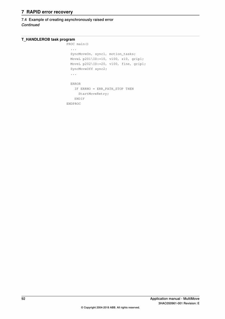
T_HANDLEROB task programPROC main()
...
SyncMoveOn, sync1, motion_tasks;
MoveL p201\ID:=10, v100, z10, grip1;
MoveL p202\ID:=20, v100, fine, grip1;
SyncMoveOff sync2;
...
ERROR
IF ERRNO = ERR_PATH_STOP THEN
StartMoveRetry;
ENDIF
ENDPROC
92 Application manual - MultiMove3HAC050961-001 Revision: E
© Copyright 2004-2018 ABB. All rights reserved.
7 RAPID error recovery7.4 Example of creating asynchronously raised errorContinued
7.5 Example with movements in error handler
About this exampleIn this example, an asynchronous error can occur that requires the robot to moveto another position to resolve the error. The synchronization is suspended by usingStorePath in all tasks with synchronized movements, and restored by usingRestoPath.The instruction ArcL is used in this example. This instruction handles the processfor arc welding as well as acts as a move instruction. To understand this example,all you need to know is that it is a move instruction (similar to MoveL) which canresult in asynchronous process errors. For more information about ArcL, seeApplication manual - Arc and Arc Sensor and Technical reference manual - RAPIDInstructions, Functions and Data types.
Note
Note that the T_STN1 task program must have the instructions StorePath andRestoPath, even if there is no code between these instructions. No task programcontinues to execute its error handler until all task programs execute theStorePath instruction.
T_ROB1 task program...
SyncMoveOn, sync1, all_tasks;
ArcL p101\ID:=10, v100, seam1, weld1, weave1, z10, gun1\WObj:=wobj_stn1;
...
ERROR
IF ERRNO=AW_WELD_ERR OR ERRNO=ERR_PATH_STOP THEN
StorePath;
IF ERRNO=AW_WELD_ERR THEN
gun_cleaning;
ENDIF
RestoPath;
StartMoveRetry;
ENDIF
...
PROC gun_cleaning()
VAR robtarget p199;
p199 := CRobT(\Tool:=gun1 \WObj:=wobj0);
MoveL pclean, v100, fine, gun1;
...
MoveL p199, v100, fine, gun1;
ENDPROC
T_ROB2 task program...
SyncMoveOn, sync1, all_tasks;
Continues on next pageApplication manual - MultiMove 933HAC050961-001 Revision: E
© Copyright 2004-2018 ABB. All rights reserved.
7 RAPID error recovery7.5 Example with movements in error handler
ArcL p201\ID:=10, v100, seam2, weld2, weave2, z10, gun2\WObj:=wobj_stn1;
...
ERROR
IF ERRNO=AW_WELD_ERR OR ERRNO=ERR_PATH_STOP THEN
StorePath;
IF ERRNO=AW_WELD_ERR THEN
gun_cleaning;
ENDIF
RestoPath;
StartMoveRetry;
ENDIF
...
PROC gun_cleaning()
VAR robtarget p299;
p299 := CRobT(\Tool:=gun2 \WObj:=wobj0);
MoveL pclean, v100, fine, gun2;
...
MoveL p299, v100, fine, gun2;
ENDPROC
T_STN1 task program...
SyncMoveOn, sync1, all_tasks;
MoveExtJ angle_20\ID:=10, vrot50, z10;
...
ERROR
IF ERRNO=ERR_PATH_STOP THEN
StorePath;
RestoPath;
StartMoveRetry;
ENDIF
...
94 Application manual - MultiMove3HAC050961-001 Revision: E
© Copyright 2004-2018 ABB. All rights reserved.
7 RAPID error recovery7.5 Example with movements in error handlerContinued
8 Running a subset of a MultiMove system8.1 How to continue with one or more drive units inactive.
OverviewIt is possible to disconnect a drive module and continue working, for example:
• if a drive module is required elsewhere due to failure or similar.• for tuning purposes during commissioning, for instance programming one
robot at a time while the others are temporarily shut down.Make sure the application allows work to continue without this drive module, byusing the procedure Continue with the Drive Module Disconnect function onpage 95.But if one of the following conditions are fulfilled then Continue with alternativeconfiguration on page 96.
• The first alternative fails.• The limit switches are used on the robot.• The drive module needs to be moved (e.g. for repair or installation in another
cell).
Tip
Sometimes it is necessary to change the program and/or configuration so thatthe application will work with one less drive module.
Continue with the Drive Module Disconnect functionThis procedure shows how to let the functional robots continue with theirapplications without changing the configuration. This requires that the functionalrobots have no dependencies to the disconnected robot, or additional axesconnected to the same drive module.This is a brief description how to disconnect the drive module, for more detailedinformation see Product manual - IRC5, section Connections - Connection of theDrive Module Disconnect.
Info/illustrationAction
Make sure that the system parameterAllow_Drive_Module_Disconnectis set to true.
1
Switch to manual mode.2
Make sure the controller is in Motors Offstate.
3
Continues on next pageApplication manual - MultiMove 953HAC050961-001 Revision: E
© Copyright 2004-2018 ABB. All rights reserved.
8 Running a subset of a MultiMove system8.1 How to continue with one or more drive units inactive.
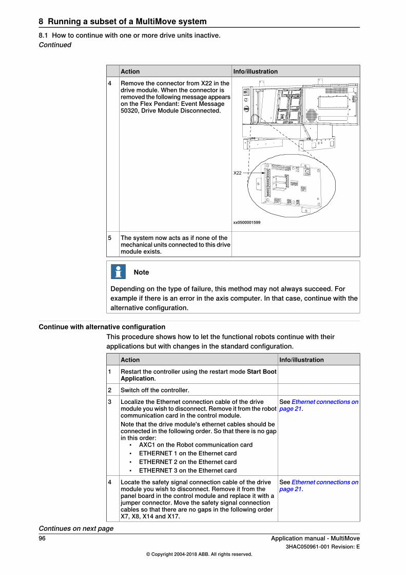
Info/illustrationAction
xx0500001599
Remove the connector from X22 in thedrive module. When the connector isremoved the following message appearson the Flex Pendant: Event Message50320, Drive Module Disconnected.
4
The system now acts as if none of themechanical units connected to this drivemodule exists.
5
Note
Depending on the type of failure, this method may not always succeed. Forexample if there is an error in the axis computer. In that case, continue with thealternative configuration.
Continue with alternative configurationThis procedure shows how to let the functional robots continue with theirapplications but with changes in the standard configuration.
Info/illustrationAction
Restart the controller using the restart mode Start BootApplication.
1
Switch off the controller.2
SeeEthernet connections onpage 21.
Localize the Ethernet connection cable of the drivemodule you wish to disconnect. Remove it from the robotcommunication card in the control module.
3
Note that the drive module's ethernet cables should beconnected in the following order. So that there is no gapin this order:
• AXC1 on the Robot communication card• ETHERNET 1 on the Ethernet card• ETHERNET 2 on the Ethernet card• ETHERNET 3 on the Ethernet card
SeeEthernet connections onpage 21.
Locate the safety signal connection cable of the drivemodule you wish to disconnect. Remove it from thepanel board in the control module and replace it with ajumper connector. Move the safety signal connectioncables so that there are no gaps in the following orderX7, X8, X14 and X17.
4
Continues on next page96 Application manual - MultiMove
3HAC050961-001 Revision: E© Copyright 2004-2018 ABB. All rights reserved.
8 Running a subset of a MultiMove system8.1 How to continue with one or more drive units inactive.Continued
Info/illustrationAction
Switch on the power to the controller.5
Select a new robot system that is configured without thedisconnected mechanical unit.
6
Note that the configuration has to be in accordance withthe connections in step 3.
Application manual - MultiMove 973HAC050961-001 Revision: E
© Copyright 2004-2018 ABB. All rights reserved.
8 Running a subset of a MultiMove system8.1 How to continue with one or more drive units inactive.
Continued
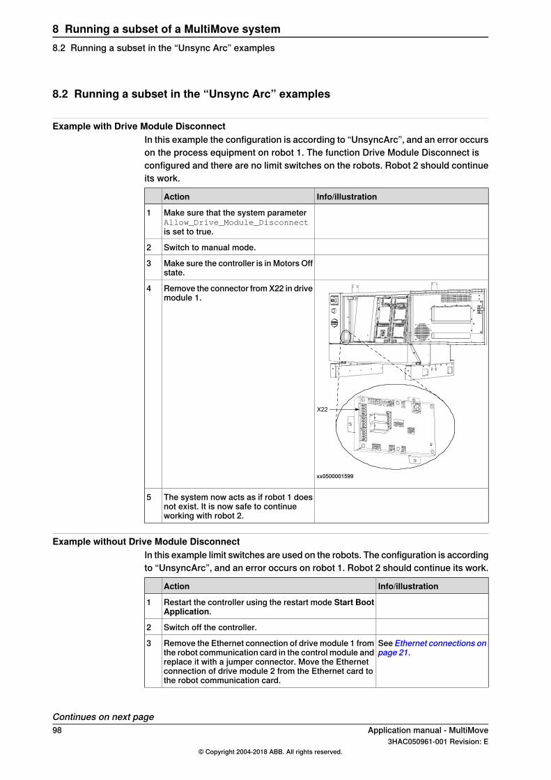
8.2 Running a subset in the “Unsync Arc” examples
Example with Drive Module DisconnectIn this example the configuration is according to “UnsyncArc”, and an error occurson the process equipment on robot 1. The function Drive Module Disconnect isconfigured and there are no limit switches on the robots. Robot 2 should continueits work.
Info/illustrationAction
Make sure that the system parameterAllow_Drive_Module_Disconnectis set to true.
1
Switch to manual mode.2
Make sure the controller is in Motors Offstate.
3
xx0500001599
Remove the connector from X22 in drivemodule 1.
4
The system now acts as if robot 1 doesnot exist. It is now safe to continueworking with robot 2.
5
Example without Drive Module DisconnectIn this example limit switches are used on the robots. The configuration is accordingto “UnsyncArc”, and an error occurs on robot 1. Robot 2 should continue its work.
Info/illustrationAction
Restart the controller using the restart mode Start BootApplication.
1
Switch off the controller.2
See Ethernet connections onpage 21.
Remove the Ethernet connection of drive module 1 fromthe robot communication card in the control module andreplace it with a jumper connector. Move the Ethernetconnection of drive module 2 from the Ethernet card tothe robot communication card.
3
Continues on next page98 Application manual - MultiMove
3HAC050961-001 Revision: E© Copyright 2004-2018 ABB. All rights reserved.
8 Running a subset of a MultiMove system8.2 Running a subset in the “Unsync Arc” examples
Info/illustrationAction
See Ethernet connections onpage 21.
Remove the safety signal connection of drive module 1from X7 on the panel board in the control module. Movethe safety signal connection of drive module 2 from X8to X7. Then push the jumper connector in the X8 connect-or.
4
Switch on the power to the controller.5
Select a new robot system that is configured withoutrobot 1.
6
Note that the configuration has to be in accordance withthe connections in step 3. I.e. the remaining robot willbe referred to as robot 1.
Tip
The same actions can be taken if the axis computer fails, or other failure thatcannot be helped with Drive Module Disconnect.
Application manual - MultiMove 993HAC050961-001 Revision: E
© Copyright 2004-2018 ABB. All rights reserved.
8 Running a subset of a MultiMove system8.2 Running a subset in the “Unsync Arc” examples
Continued

This page is intentionally left blank
IndexAActivate at Start Up, 32, 37Allow Drive Module Disconnect, 32Allow move of user frame, 32, 37Argument, 34, 39Argument 2, 34, 39asynchronously raised errors, 89Auto mode, 54
Bbase coordinate system, 45–46
Ccalibration, 41circular movements, 82Collision Detection, 83configuration, 29controller, 19Controller, 30Controller topic, 30control module, 20coordinated, 52coordinated synchronized movements, 71coordinated work object, 59coordinate systems, 41, 45coordination, 14corner zones, 75create MultiMove system, 27
Ddata types, 55deactivate tasks, 53Deactivation Forbidden, 32, 37drive module, 25Drive Module Disconnect, 95drive modules, 19Drive Module User Data, 32dummy instructions, 78
EERR_PATH_STOP, 89error recovery, 87Ethernet connections, 21example applications, 15
Ffailure in the hardware, 95FlexPendant, 47functions, 56
Hhardware, 19hardware failure, 95
II/O, 34I/O topic, 34ID, 57identno, 55independent movements, 60installation, 19instructions, 55IsSyncMoveOn, 56
Jjogging, 48, 52
MMechanical Unit, 32, 37Mechanical Unit Group, 30, 35, 37mechanical unit menu, 52modify position, 80Motion, 32Motion Planner, 32, 35, 37MotionTask, 30, 35, 37motion tasks, 13Motion topic, 32MoveExtJ, 56move instructions, 78Move PP To Main, 51
NNORMAL, 30
Oobject coordinate system, 45–46options, 7, 13
PPERS, 84positioner, 14ProcerrRecovery, 89, 91Production window, 51program example, 61, 64, 72programming, 55
RRAPID, 55RAPID example, 61, 64, 72relative calibration, 42Relative n points, 42RestoPath, 89, 93robot, 14robot speed, 79
Ssafety, 11Safety signal connections, 23, 26select tasks, 53semi coordinated movements, 63SEMISTATIC, 30speed, 79Speed Control Percent, 33, 37Speed Control Warning, 33, 35, 37STATIC, 30status bar, 48stop points, 75StorePath, 89, 93SyncArc, 17, 37, 46, 64, 72synchronization, 14, 63, 77synchronizing argument, 57syncident, 55, 84SyncMoveOff, 56, 71SyncMoveOn, 56, 71SyncMoveUndo, 56, 84System Input, 34, 39System Output, 34, 39system parameters, 30
TTask, 30, 35, 37
Application manual - MultiMove 1013HAC050961-001 Revision: E
© Copyright 2004-2018 ABB. All rights reserved.
Index
TASK PERS, 84task program, 14tasks, 53, 55, 58tool orientation, 82Type, 30, 35, 37
UUNDO, 84UnsyncArc, 16, 35, 45, 61, 98Use Mechanical Unit Group, 30, 35, 37
Use Motion Planner, 31, 35, 37user coordinate system, 45–46user interface, 47
WWaitSyncTask, 55, 63work object, 59world coordinate system, 45–46World Zones, 83
102 Application manual - MultiMove3HAC050961-001 Revision: E
© Copyright 2004-2018 ABB. All rights reserved.
Index

ABB AB, RoboticsRobotics and MotionS-721 68 VÄSTERÅS, SwedenTelephone +46 (0) 21 344 400
ABB AS, RoboticsRobotics and MotionNordlysvegen 7, N-4340 BRYNE, NorwayBox 265, N-4349 BRYNE, NorwayTelephone: +47 22 87 2000
ABB Engineering (Shanghai) Ltd.Robotics and MotionNo. 4528 Kangxin HighwayPuDong DistrictSHANGHAI 201319, ChinaTelephone: +86 21 6105 6666
ABB Inc.Robotics and Motion1250 Brown RoadAuburn Hills, MI 48326USATelephone: +1 248 391 9000
abb.com/robotics
3HAC050961-001,Rev
E,en
© Copyright 2004-2018 ABB. All rights reserved.Specifications subject to change without notice.