Embed Size (px)
Citation preview

1/6/2014
1
Trimble Robotic Total Station Field Maintenance
Jay Haskamp – Trimble Certified TrainerFrontier Precision, Inc. – St. Cloud, MN
• Transport• Hard field handling• Vibration & shock from
construction equipment• Extreme temperature changes• Windy, rainy, snowy weather
IntroductionWhat happens to your robot that can have an
effect on your accuracy?
1/6/2014
2
• Instrument care and maintenance• Understand and improve your radio link• Check of electronic level• Check & adjust tribrach bubble• Check telescope for single face measurement• Check Tracker vs. Optics• Check & adjust optical plumb in S-series instrument• SurePoint, how it works
Session Agenda
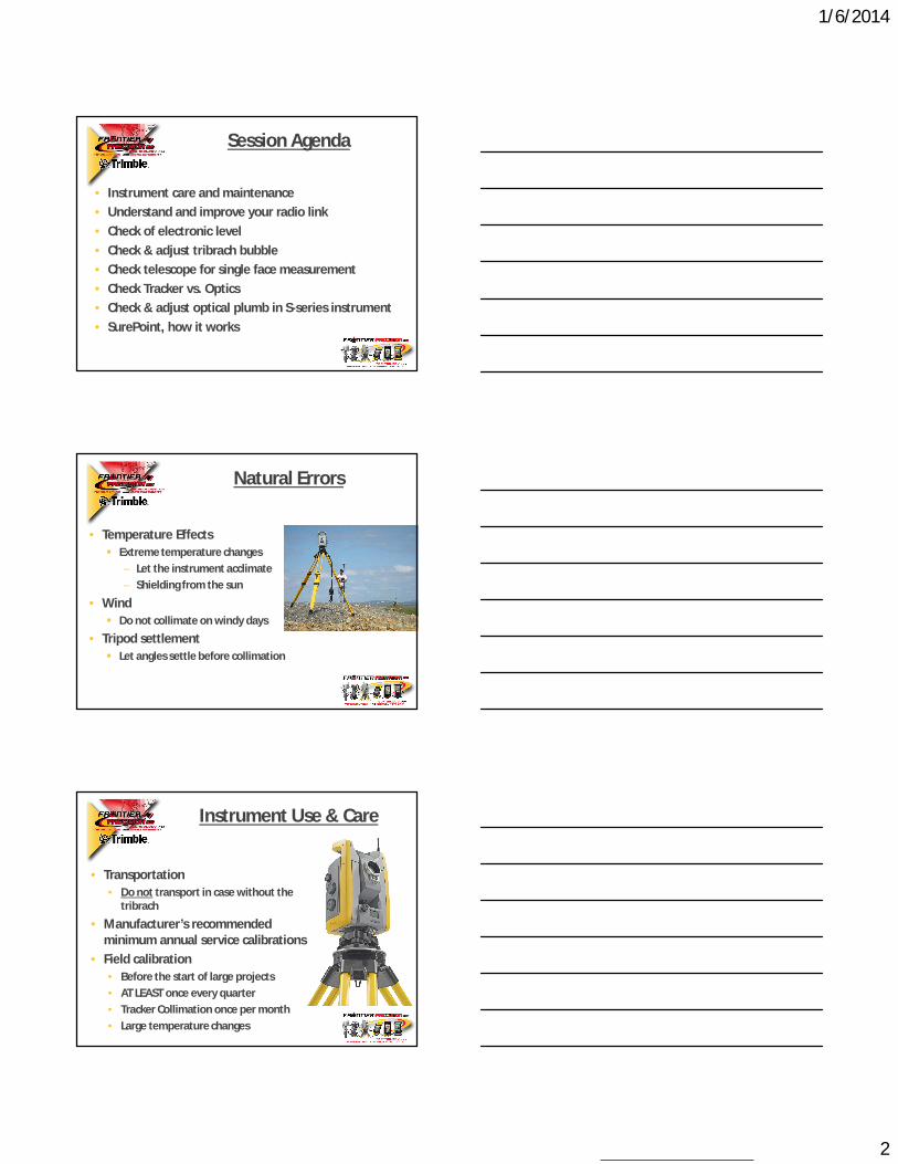
• Temperature Effects Extreme temperature changes
– Let the instrument acclimate– Shielding from the sun
• Wind Do not collimate on windy days
• Tripod settlement Let angles settle before collimation
Natural Errors
• Transportation• Do not transport in case without the
tribrach
• Manufacturer’s recommendedminimum annual service calibrations
• Field calibration• Before the start of large projects• AT LEAST once every quarter• Tracker Collimation once per month• Large temperature changes
Instrument Use & Care
1/6/2014
3
• Sufficient time for acclimation Approx 1 minute for every 1° F
• Example… 77°F transport temp. 23°F outside temp. 54 min. acclimation time
Instrument Acclimation
Robotic Radios: How they work
Antenna Angled Vertically
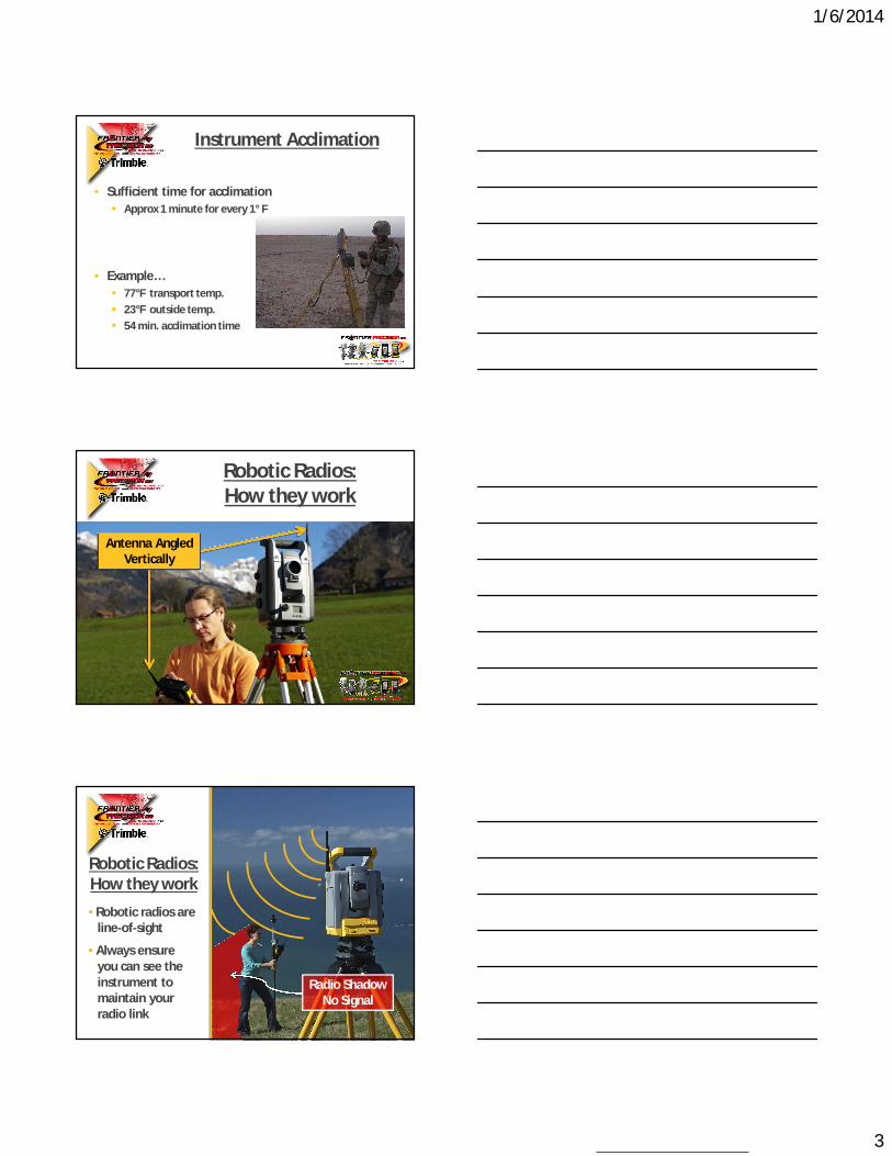
• Robotic radios are line-of-sight
• Always ensure you can see the instrument to maintain your radio link
Robotic Radios: How they work
Radio ShadowNo Signal
1/6/2014
4
Robotic Radios: How they work
Top View of Antenna
Signal in all directions
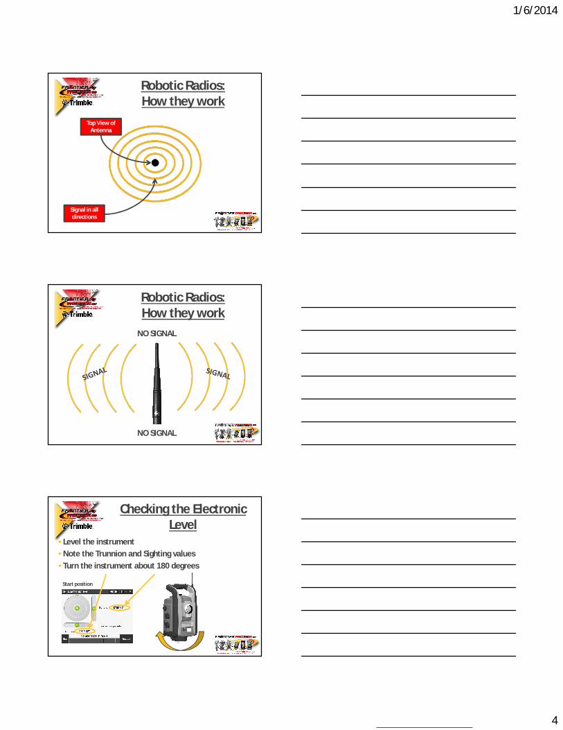
Robotic Radios: How they work
NO SIGNAL
NO SIGNAL
• Level the instrument • Note the Trunnion and Sighting values• Turn the instrument about 180 degrees
Start position
Checking the Electronic Level

1/6/2014
5
Data should be the same but with different signs
180 degreesStart position
Checking the Electronic Level
Note, if TCU is attached to the instrument it will give 50cc difference, but that is expected.
If you get different values, how will that affect the result?
Difference @ 320 ft
8 seconds 0.007 feet
Difference @160 ft
24 seconds 0.01 feet
Checking the Electronic Level
It is very important that the instrument have been powered up for about 3 minutes before you start the calibration procedure.
This is to get the compensator warmed up.
Calibrate the Electronic Level

1/6/2014
6
Calibrate the Electronic Level
It is an automated process that takes just about 1 minute to complete.
AS EASY AS….
ONE
TWO
THREE
Robot level bubble in face 2 display: The level bubble in the face 2 display has different options depending on what you want to see.
Default start-up display:Default display has a scale of 1:250 of the bubble.
Level Bubble in Face 2 Display
Change scale:With a short press on the middle key (↓) it is possible to changethe scale of the bubble, from 1:250 to 1:100, 1:10 or 1:1. In the lastoption 1:1 it is very sensitive! In the top left corner the currentscale is displayed.
Level Bubble in Face 2 Display

1/6/2014
7
Level Bubble in Face 2 Display
Digital info:With a long press on the middle key (↓) it is possible to show digitalinfo instead.
Level Bubble in Face 2 Display
Why should I use this?There is no need to level the instrument better than the first display 1:250, the compensator takes care of the minor miss leveling that might still be there.
It is much more important to calibrate the compensator regularly!
However some users still want to level the instrument very accurately, which is why these options exist.
Once your S Series robot is digitally leveled, check adjust the level bubble in the tribrach.
Adjust the Tribrach Bubble
1/6/2014
8
Adjust the Tribrach Bubble
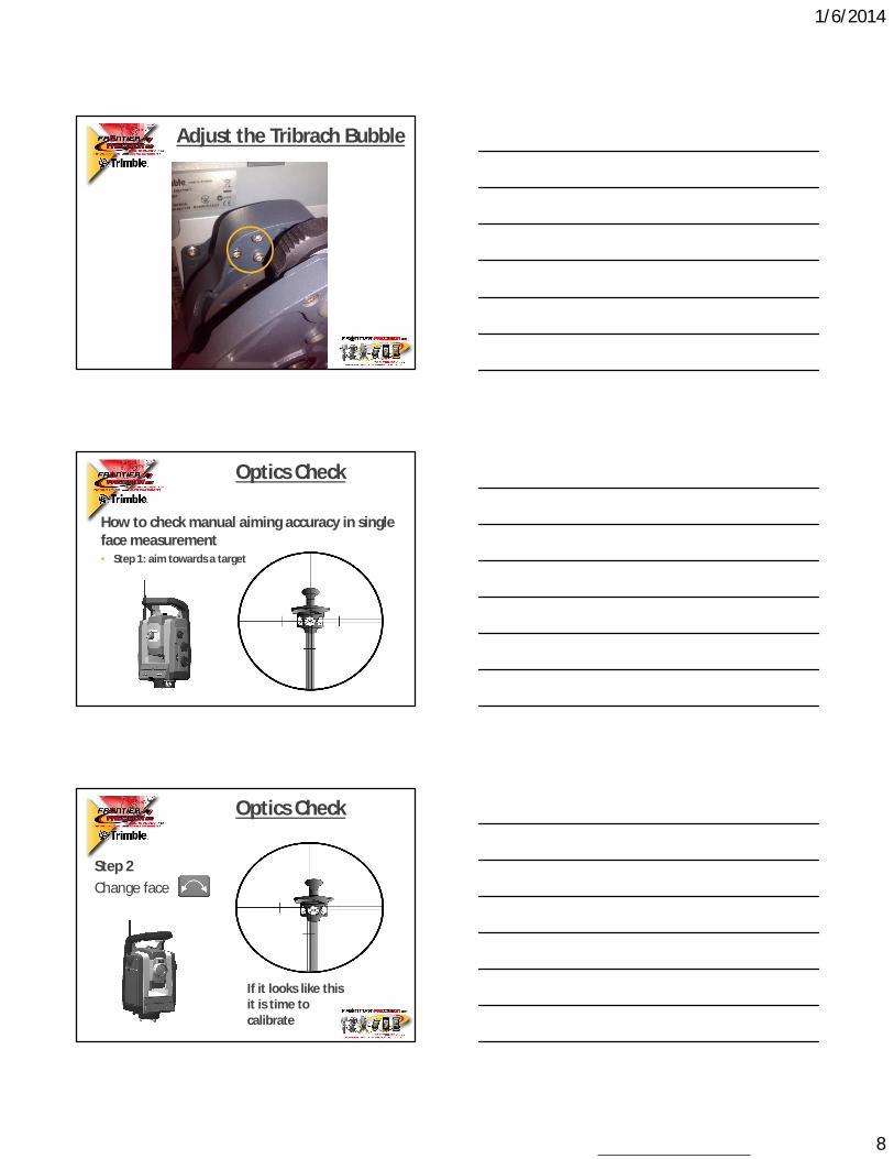
How to check manual aiming accuracy in single face measurement• Step 1: aim towards a target
Optics Check
Step 2Change face
If it looks like this it is time to calibrate
Optics Check

1/6/2014
9
Step 3: Calibrate if needed
Optics Check
Note: The prism must be at least 100 meters from your total station for this adjustment.
Step 3 (Cont.): Perform Collimation
Optics Check
Note: The prism must be at least 100 meters from your total station for this adjustment.
Step 3 (Cont.): Check Collimation Results
Optics Check

1/6/2014
10
Difference between aiming Manually (left) and with Autolock (right).
Manual aiming Tracker aiming
How to check aiming:Optical vs. Tracker
• Coaxial optical path• Coaxial tracker transmitter• Coaxial tracker detector
Telescope Overview
Step 1: Aim to prism with Tracker (Autolock) disabled
Optical vs. Tracker Check

1/6/2014
11
Optical vs. Tracker Check
• You can also check the HA and VA angles
Step 2: Enable the Tracker (Autolock):
Optical vs. Tracker Check
Optical vs. Tracker Check
• Compare HA and VA with data from the Autolock measurement

1/6/2014
12
Optical vs. Tracker Check
Step 3: Calibrate if needed Note: This is an automated adjustment. Access will notify you when the process is complete.
When the adjustment is finished, re-do Steps 1 & 2 to check the results.
Laser adjustment plate
Aim to a Laser adjustment plate
Laser Pointer Adjustment
Laser Pointer Adjustment
Laser adjustment plate
Y
1/6/2014
13
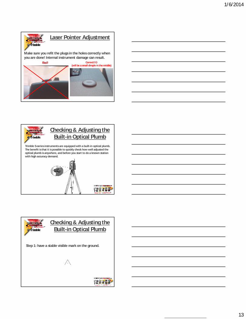
Make sure you refit the plugs in the holes correctly when you are done! Internal instrument damage can result.
Bad! Correct!!(will be a small dimple in the middle)
Laser Pointer Adjustment
Trimble S-series instruments are equipped with a built-in optical plumb. The benefit is that it is possible to quickly check how well adjusted the optical plumb is anywhere, and before you start to do a known station with high accuracy demand.
Checking & Adjusting the Built-in Optical Plumb
Checking & Adjusting the Built-in Optical Plumb
Step 1: have a stable visible mark on the ground.

1/6/2014
14
Checking & Adjusting the Built-in Optical Plumb
Step 2: Set the instrument up on a tripod so you get about 1.5 m (5 ft) instrument height. Then level the instrument over the reference point as you normally would. Here is a perfectly aimed cross-hair when looking through the optical plumb after the set-up. However you have no idea if it is good or not, it just might look good.
1,5m(5 ft)
~ 1,5m(5 ft)
Step 3: Now turn the instrument about 180 degrees.Look through the optical plumb again. If it still points correctly the optical plumb is perfectly aligned, but if it looks like the picture below it is time to adjust the optical plumb.
Checking & Adjusting the Built-in Optical Plumb
Step 4: Find the tools needed.In the instrument case, there is a tool kit to be used, for this adjustment it is the two smaller hex keys (the other larger hex key is to adjust the tribrachbubble).
Checking & Adjusting the Built-in Optical Plumb

1/6/2014
15
Step 5: Adjusting the optical plumb “horizontally”Now we are coming to the critical part, BE CAREFUL, do not over-tighten any screws.
To start, place the two tools as shown in the picture below.
Checking & Adjusting the Built-in Optical Plumb
Which screw to start with?
In this example the cross-hair needs to be adjusted to the right. To start, release the right screw counter clockwise, then turn the screw on the left side clockwise to adjust the optical plumb to the right. Only adjust it half the way.
12
Counterclockwise
Clockwise
Checking & Adjusting the Built-in Optical Plumb
Step 6: Adjusting the optical plumb “vertically”Do the same as above but now vertically, In this example the cross-hair needs to be adjusted “down”. To start, release the bottom screw counter clockwise and then the screw in the top clockwise to adjust the optical plumb down.
Checking & Adjusting the Built-in Optical Plumb
1/6/2014
16
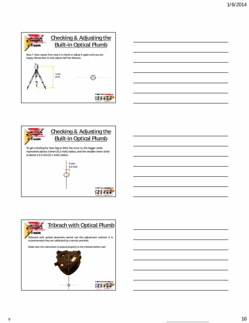
Step 7: Now repeat from step 2 to check or adjust it again until you are happy. Remember to only adjust half the distance.
~1,5m(5 ft)
Checking & Adjusting the Built-in Optical Plumb
To get a feeling for how big or little the error is, the bigger circle represents about a 5mm (0.2 inch) radius, and the smaller inner circle is about a 2.5 mm (0.1 inch) radius.
5 mm 0.2 inch
Checking & Adjusting the Built-in Optical Plumb
Tribrachs with optical plummets cannot use this adjustment method. It isrecommended they are calibrated by a service provider.
Make sure the instrument is seated properly in the tribrach before use!
Tribrach with Optical Plumb
Y

1/6/2014
17
• General rule, each year or after 3000h (about 8h/day 365days)
• Optical alignment of EDM and Tracker• Calibration of EDM• Calibration of servo and angle system• Servo focus calibration and check• Camera (Video) calibration• Updates according to Service Bulletins• Greasing of moving parts• ..etc
What should be done at the service shop?
Biggest Sources to Bad Measurements
3.) Bad (calibrated) instrument
2.) Bad Tribrach
1.) Bad tripod or instrument set-up
• Control loop active all the time• Always turns instrument to the current
reference angle
• Reference angle only changed when• Knobs are turned• Position commands are given• Instrument is turned firmly so that it
enters friction mode
• If instrument is disturbed slightly it will be aimed back at target
• Buttons pushed on instrument• Contact with instrument when looking
through telescope • Wind
SurePoint™

1/6/2014
18
• What happens when you aim at a plumb line and turn the vertical knob?
• Old systems will only turn the vertical motor• The aim will not follow the plumb line but the horizontal
angle will be compensated for this drift
HA: 143.4532VA: 95.0000VA: 90.0000VA: 85.0000VA: 80.0000VA: 75.0000VA: 70.0000VA: 65.0000VA: 60.0000VA: 55.0000VA: 100.0000VA: 50.0000HA: 143.4478HA: 143.4431HA: 143.4363HA: 143.4301HA: 143.4268HA: 143.4216HA: 143.4141HA: 143.4097HA: 143.4051HA: 143.4004
Collimation error the old way
• SurePoint™ will feed the corrections back into the control loop when the vertical knob is turned!
• SurePoint™ will use both motors and make the instrument follow the plumb line
VA: 95.0000VA: 90.0000VA: 85.0000VA: 80.0000VA: 75.0000VA: 70.0000VA: 65.0000VA: 60.0000VA: 55.0000VA: 100.0000VA: 50.0000HA: 143.4532
Collimation error with SurePoint™
• Compact durable design
• Accurate and reliable• Low power
consumption• Refresh rate of
6 Hz• Mounted in the center
of the instrument
Tilt Sensor
1/6/2014
19
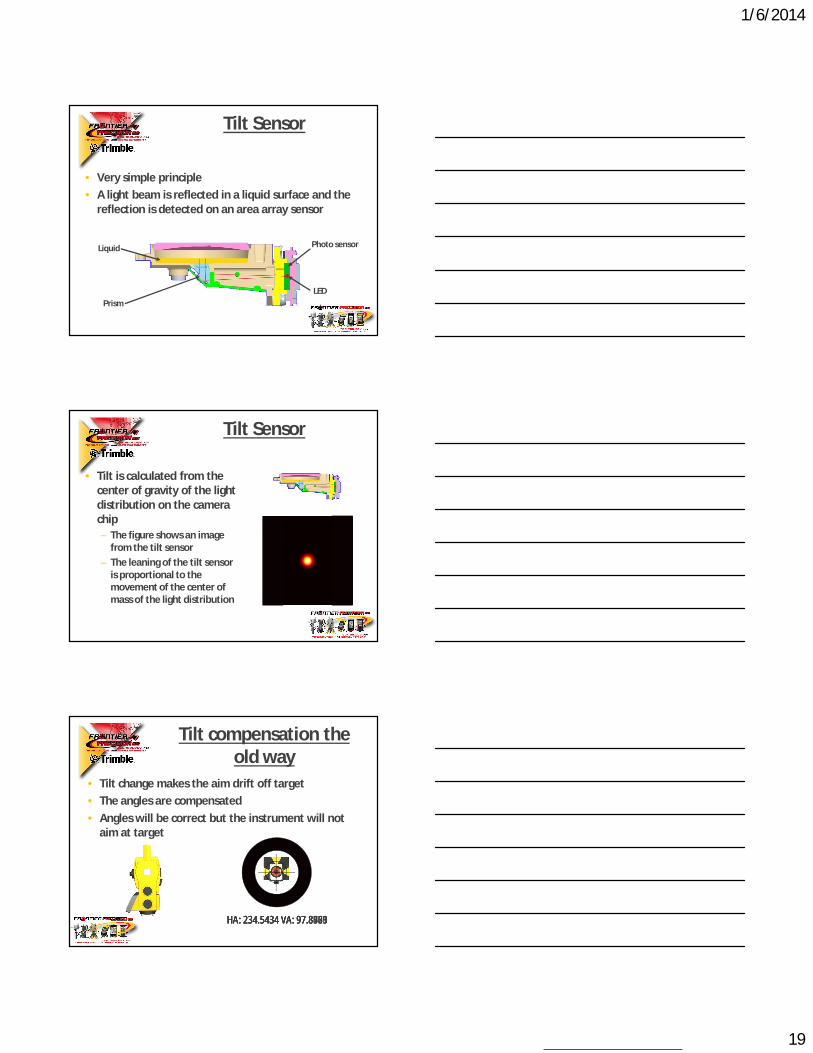
• Very simple principle• A light beam is reflected in a liquid surface and the
reflection is detected on an area array sensor
Liquid
Prism
Photo sensor
LED
Tilt Sensor
• Tilt is calculated from the center of gravity of the light distribution on the camera chip – The figure shows an image
from the tilt sensor– The leaning of the tilt sensor
is proportional to the movement of the center of mass of the light distribution
Tilt Sensor
• Tilt change makes the aim drift off target• The angles are compensated• Angles will be correct but the instrument will not
aim at target
HA: 234.5434 VA: 97.8320HA: 234.5434 VA: 97.8461HA: 234.5434 VA: 97.8603HA: 234.5434 VA: 97.8789HA: 234.5434 VA: 97.8975
Tilt compensation the old way

1/6/2014
20
• Tilt change makes the aim drift off target• SurePoint™ corrects the position back on to the
target
HA: 234.5434 VA: 97.8320
Tilt compensation with SurePoint™
• Check your instruments regularly• Field checks are necessary when working with
Autolock or Robotic Total Stations• Instruments should be calibrated annually via
Service Provider• Robotic trackers need to be field collimated regularly• Regular maintenance will go a long way in
maintaining the accuracy of your instruments
Summary