Embed Size (px)
Citation preview

Robotic Implant to Apply Tissue Traction Forcesin the Treatment of Esophageal Atresia
Dana D. Damian, Member, IEEE, Slava Arabagi, Assunta Fabozzo, M.D., Peter Ngo, M.D.,Russell Jennings, M.D., Michael Manfredi, M.D., and Pierre E. Dupont, Fellow, IEEE
Abstract— This paper introduces robotic implants as a novelclass of medical robots in the context of treating esophagealatresia. The robotic implant is designed to apply traction forcesto the two disconnected esophageal segments to induce sufficientgrowth so that the two ends can be joined together to forma functioning esophagus. In contrast to the current manualmethod of externally applying traction forces, the implantoffers the potential to avoid prolonged patient sedation andto substantially reduce the number of X-rays required. Aprototype design is presented along with evaluation experimentsthat demonstrate its capabilities to apply traction forces to exvivo esophageal tissues.
I. INTRODUCTION
Surgical robots have yielded benefits in medicine by aug-menting the surgeon’s physical capabilities while enablingthe integration of multi-modal imaging and sensory data [1].The greatest potential impact is when the use of roboticsin comparison with manual surgery results in both reducedinvasiveness together with superior outcomes. Towards re-ducing invasiveness, medical robots are being designed thatmove inside the body without reliance on a rigid mechanicalconnection outside the patient. Examples include tetheredmobile robots such as Heartlander that can perform localizedsensing, mapping and treatment over the entire surface of theheart [2]. Another class of examples is the tethered intestinalcrawlers designed to increase the capabilities of colonoscopywhile simultaneously reducing its trauma [3] [4] [5]. In addi-tion, tetherless unactuated smart pills incorporating wirelesscameras and other sensors have opened up new directions inmedical diagnostics [6] [7] [8] [9] [10].
A completely new category of medical robot that hasyet to be explored is that of robotic implants. This fieldcharacterizes robots that autonomously regulate biologicalprocesses inside the body for long periods of time. Thebenefits of robotic implants are multiple: they remove thenecessity of repetitive surgical interventions, and consequentinfection risks and pain, while restoring degraded or missingbiological functionalities. While they may move through thebody, they may also reside in one location and employ theirdegrees of freedom to interact with tissue structures. Forexample, they could perform such tasks as adjusting flowrates through valves and organs or act to change the lengthor compliance of tissues.
*This work was supported by Swiss National Science Foundation grantPBZHP2 143344.
D.D. Damian, S. Arabagi, A. Fabozzo, P. Ngo, R. Jennings, M. Manfrediand P. Dupont are with Boston Children’s Hospital, Harvard Medical School,Boston, U.S.A. [email protected]
A B C
Esophageal
segments
Sutures
Robotic
implant
Fig. 1. Inducing tissue growth through traction forces. A. Long-gapesophageal atresia. B. Current treatment uses sutures looped around ribsand tied off outside back. C. Proposed robotic implant.
One example for which a robotic implant would beextremely beneficial is esophageal atresia (EA). This is acongenital defect afflicting about 1000 babies per year inthe US, in which the ends (segments) of the esophagusare not connected (see Fig. 1A). Other applications includeconditions where lengthening of tubular structures is desired,such as the bowel and the vasculature [11]. If the gapbetween the two ends is small, they can be surgicallyconnected. When the gap is 3cm or more, however, it isnot possible to stretch the tissue sufficiently to create aconnection. For these cases, known as long-gap esophagealatresia (LGEA), the best current solution consists of applyingtraction forces to each end of the esophagus for 14 days inaverage (Foker’s technique) [12] [13]. This causes each endof the esophagus to grow (lengthen) in the direction of theforces. When sufficient lengthening is achieved, the two endsare surgically connected. As shown in Fig. 1B, the tractionforces are currently applied using sutures that are loopedaround the ribs and tied off outside the patient’s back. Everyday the sutures are manually tightened and X-ray imaging isused about every other day to assess tissue lengthening andto check for potential suture tear out.
While producing superior outcomes to alternative proce-dures, the child is sedated and kept on a ventilator for theduration of the treatment. Sedation is necessary to avoidmotion of the rib cage that occurs during arm movementas it may lead to tearing out the traction sutures. It wouldbe extremely beneficial to these patients if (1) multi-weeksedation could be avoided so as to eliminate any effect onlong-term neurocognitive development, (2) X-ray imaging
2014 IEEE International Conference on Robotics & Automation (ICRA)Hong Kong Convention and Exhibition CenterMay 31 - June 7, 2014. Hong Kong, China
978-1-4799-3684-7/14/$31.00 ©2014 IEEE 786

1 cm
Esophagus
segment
Robotic
implant
Fig. 2. Positioning of robotic implant within the chest.
to verify progress could be reduced or eliminated, and (3)the need for re-operation due to suture tear out could bereduced. A robotic implant has the potential to resolve theseshortcomings. As depicted in Fig. 1C, such a device couldapply tension to both ends of the esophagus simultaneously.Since sutures are no longer tensioned around ribs, the pa-tient could avoid sedation. In addition, tissue lengtheningand force could be monitored and controlled using implantsensors reducing the need for X-rays while also enablingmore precise control of traction forces.
The contribution of this paper is to propose, fabricateand perform initial testing of a robotic implant for treatingLGEA. Section II describes alternate approaches to treatingLGEA. Section III presents design requirements and implantdesign. Calibration and evaluation experiments appear inSection IV and conclusions are given in the final section.
II. RELATED WORK
The repair of LGEA is considered one of the most difficultsurgical interventions in pediatrics. A number of surgicalprocedures are being applied in order to restore the struc-ture and functionality of the esophagus [14]. Some LGEAtreatments aim to complete the esophagus using a surrogatetissue for the missing segment. Colonic, gastric and jejunalgraft interposition are among the most popular [15] [16].However, there is a general agreement that using the patient’sown esophagus should lead to superior results compared toany esophageal replacement [14].
The long gap between the two esophageal segments ledto the development of techniques that attempt to stretch thesegments and finally connect the two ends (anastomosis). Awidely used method of lengthening the esophageal segments
X
H
4 years
2 years
8 years
8 months
3 months
A
1 cm
B
Age X[mm] H[mm]
3 months 10 50
8 months 15 55
2 years 30 100
4 years 35 105
8 years 40 140
C
Fig. 3. Available space for robotic implant shown on X-ray image of eightyear old patient. A. Front view. B. Lateral view. C. Clinical estimate ofvolume available based on patient age.
is circular myotomy, which proposes the elongation of thehighly stretchy submucosal layer of the esophagus in orderto bring the segments together [17]. However, because thislayer is highly stretched, while the other layers are dividedand not included in the anastomosis, the method leads toleaks and other complications at the myotomy sites.
A different LGEA technique uses a multistaged ex-trathoracic elongation process of the esophagus seg-ments [18] [19] [20]. This method involves making se-quential skin incision sites to which the esophagus segmentis connected under tension, until its length is sufficient toperform anastomosis.
Lengthening the esophagus axially is an alternate vi-able approach. This has been attempted using magneticforces, e.g., electromagnetic bougienage [21], hydraulicallycontroller magnetic forces [22]. Although axial traction ismechanically advantageous in the LGEA, the magnets tendto erode the esophagus internal tissue where they reside, dueto increasing attraction magnetic forces, leading to the riskof magnet evasion into the body.
Foker’s technique, as described in the previous section,has been used in numerous cases and relies on manual andperiodic application of traction forces on sutures loops thatare attached to the esophagus segments [12] [13] [23]. Overthe course of a couple of weeks, suture tension is adjusteddaily to induce lengthening of the esophageal segmentsthrough two incision sites on the patient’s back. While asuccessful technique for cases of varying complexity, the ap-proach has several shortcomings as described earlier. Theseinclude the need for multi-week sedation, frequent X-raysto assess progress and the potential for the (typically) fourpledgeted suture loops to tear out of a segment necessitatingre-operation. Furthermore, the elongated tissue has a reducedlumen size (stricture) potentially because of the “necking”that occurs with the current suture attachment method. Therobotic implant introduced here is based on Foker’s techniqueand its design is intended to address these shortcomings.
787

TABLE IIMPLANT DESIGN REQUIREMENTS
Requirements Value UnitMaximum force 4 NMaximum gap size 45 mmTargeted child age 2 years
III. ROBOTIC IMPLANT DESIGN
The concept for the robotic implant is depicted in Fig. 2.In the proposed approach, a motorized implant will applyequal and opposite forces to the two esophageal segments.It will be positioned on the right side of the chest, awayfrom the heart and displace a small portion of the volumenormally filled by the right lung. In the anterior-posteriordirection, it will be positioned so as to avoid compression ofthe main stem bronchus. To avoid the need for sedation, thedevice will not be attached to the ribs, but instead will be“floating” in the chest, supported by the esophageal segmentsand surrounding tissue.
These clinical considerations regarding implant position-ing, as well as the age of the child, are determining factors forthe space available for the robotic implant. An estimation ofthe available space is listed in Fig. 3C. Miniaturization is oneof several challenges in prototype design. The approach takenhere was to develop a device sized for a two-year-old patientand in future versions reduce its size for younger patients.Furthermore, while it may be possible to create a wirelessimplant in the future, it is assumed here that a cable willexit the patient’s chest to supply power and communicationsignals.
While the effect of force variation with time on tissuelengthening is not known, the clinical evidence suggests thatthe current approach of increasing force once a day and thenallowing the tissue to relax is effective. By incorporating bothforce and position sensors in the implant, traction force canbe programmed to replicate current clinical practice whilealso monitoring tissue lengthening. In this manner, X-raymonitoring can be significantly reduced.
Preliminary experiments to measure applied suture forcesindicate forces are in the range of 2-4N. For these cases, thesutures were subjected to significant friction because theywere pulled out of the body. These traction forces weresufficient to elongate the tissue about 5mm per day [24].In the technique described in [22], the axial traction forceon the esophagus was 0.5N. Regarding the gap between thetwo esophageal segments, a typical gap size is 45mm, thoughit can also reach up to 100mm. Based on these consider-ations, the force production and sensing specifications forthe implant were set at 5N while the travel and positionsensing distance was set to 45mm. The design specificationsare summarized in Table I.
The current method of suture attachment to esophagealsegments using pledgeted suture loops is illustrated inFig. 4A [23]. The proposed alternative method of attachmentto the robotic implant appears in Fig. 4B. In the proposedapproach, the tissue is sutured to a rigid ring such that the
Traction force
Traction force
A B
Suture
holes
Traction
sutures
Esophagus
segment
Suture
ring
Pledget
Esophagus
segment
Fig. 4. Suture attachment methods. A. Standard method using fourpledgeted suture loops. B. Proposed attachment method using ring to whichtissue is sutured.
traction force is distributed more uniformly to the tissue and,furthermore, esophagus diameter is maintained with the goalof avoiding the “necking” and stricture inherent in the currentapproach.
A. Implant design
To replicate manual force application, the implant shouldbe capable of applying a desired force and then holding theactuator position associated with that force until the nextadjustment time. The proposed robotic implant automatesthe tissue lengthening process.
The non-continuous manual traction operation currentlyperformed on the esophagus requires an automatic mecha-nism that can hold the position of the esophagus segmentfor most of the time and actuate in short time bursts. Thissuggests the use of a nonbackdrivable transmission whichwas implemented using a rack and worm gear combinationas shown in Fig. 5. The worm gear is coupled to a DC motorand mounted on an aluminum car sliding on a polymer rackreinforced with an embedded steel rod. As shown, the lengthof the rack is 6cm, but this can be adjusted for differentLGEA gaps.
The esophageal segments are sutured to the two ringsmounted on the rack and sliding car, which are broughttogether as the worm moves along the rack. Distance betweenthe rings is measured using a linear potentiometer mountedon the rack (Tekscan, Inc.) and ring force is measured using asensor (Honeywell, Inc) mounted on a freely rotating hinge,as shown in Fig. 5A,B. Because the implant will be looselysutured to the chest wall to support its weight, the effect ofthe implant’s mass on the force sensor will be minimized.
B. Encapsulation
A compliant waterproof encapsulation was developed toisolate the mechanical and electrical components of therobotic implant from the surrounding tissue. The encapsu-lation must have sufficient rigidity to exclude surroundingtissue and yet be sufficiently compliant to prevent tissue
788
Motor
Suture
rings
Linear
potentiometer
Force sensor
Slider
car
B CA
Motor
Slider
car
Hinge
Force
sensor
Rack
Worm
gear
Suture
ring
Elastomeric
encapsulation
1 cm
Cap
Mounting
rings
Rod
Fig. 5. Robotic implant. A. CAD schematic. B. Implant without elastomeric sleeve. C. Encapsulated implant.
damage. To achieve these aims, the encapsulation structureconsists of a stiff internal skeleton and a soft elastomer sleeveas shown in Fig. 5C.
The internal skeleton consists of three longitudinal steelrods, two aluminum rings that act as elastomer membranefixing anchors, and two polymer end caps to secure the endsof the elastomer membrane. An outer compliant cylindricalsealing sleeve (Ecoflex 00-30, Smooth-On, Inc.) covers theentire robotic implant except for the two suture rings. Thesleeve is manufactured by first curing a flat 1.5mm thicksheet on a flat surface, and then wrapping it around a30mm wide cylinder, while sealing the edges with identicalelastomer.
The resulting soft sleeve is fixed to the two end caps ofthe implant, as well as to the two mounting rings on theslider car by means of a compression clamp, in order toreduce risks of tear outs due to holes created by screws.Furthermore, the two mounting rings serve to eliminateany stresses on the elastomeric sleeve due to slider carmotion, in order to prevent any effect on the force sensormeasurements. The steel longitudinal rods are lubricatedbefore encapsulation to promote sliding of the sleeve duringactuation. The encapsulated implant is 100mm long with adiameter of 30mm and a mass of 55g.
C. Controller design
The control task is to drive suture ring force to a specifiedset point and then hold the corresponding position whilemonitoring force and position over time. Thus, the motoris activated only during force set point control and thenonbackdrivability of the rack and gear transmission is usedto hold gap distance fixed between actuation cycles. Asshown in Fig. 6, the controller was implemented usinga Baby Orangutan 328P Board (Pololu Corp.), equippedwith an Atmel microcontroller, a motor driver, and serialcommunication capabilities. The board acquires data from
Atmega
328P
Motor
driver
MotorForce
sensor
Distance
sensor
Serial
com.
PC
Main board
5V Power
supply
Amplifier
Outside bodyInside body
Fig. 6. Controller schematic. The “Inside body” label designates theelectronics that are incorporated in the robotic implant, while the “Outsidebody” label denotes the electronics that would currently reside outside thebody of the patient.
the linear potentiometer and force sensor at 200Hz andtransmits it to an external PC via USB. The force signalis amplified and filtered using a low pass filter with a cutofffrequency of 22.7Hz. Force control was implemented, inwhich the force reference control is set from the PC andtransmitted to the board through serial communication. Anoverdamped proportional controller is used to avoid tractionforce overshoot during set-point adjustment.
IV. EXPERIMENTS
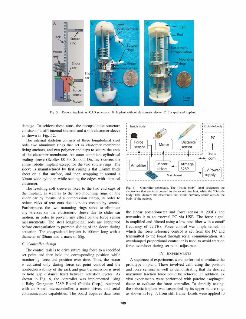
A sequence of experiments were performed to evaluate theprototype implant. These involved calibrating the positionand force sensors as well as demonstrating that the desiredmaximum traction force could be achieved. In addition, exvivo experiments were performed with porcine esophagealtissue to evaluate the force controller. To simplify testing,the robotic implant was suspended by its upper suture ring,as shown in Fig. 7, from stiff frame. Loads were applied to
789
Calibrated
weight
Robotic
implant
Fig. 7. Experimental setup for sensor calibration.
the implant through its lower suture ring. The configurationshown is for the sensor calibration experiments. For tissuetesting, the hanging weight was replaced with esophagealtissue as described later in this section.
A. Distance sensor calibration
Distance sensor calibration experiments were conductedon the encapsulated robotic implant. Three calibratedweights, 100, 200, and 300g, were attached to the lowersuture ring as shown in Fig. 7. For each weight, the gap wasset at distances of 40, 30, 20, and 10mm, in descendingand ascending order, using a digital caliper. The outputof the distance sensor acquired by the microcontroller wasrecorded.
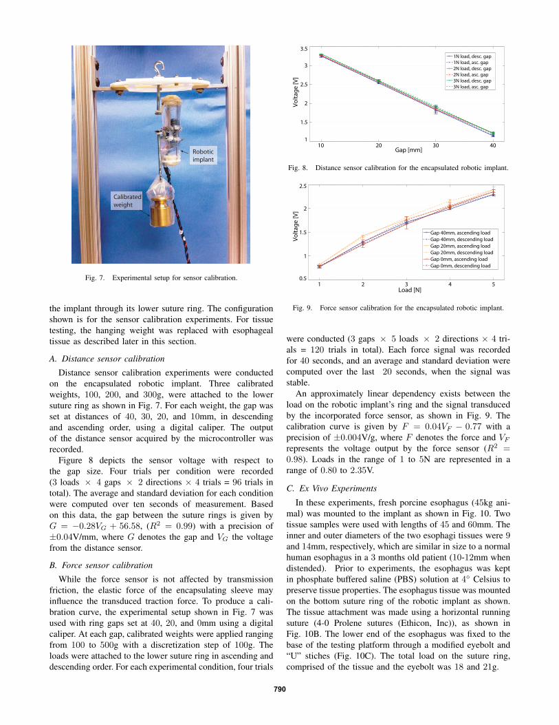
Figure 8 depicts the sensor voltage with respect tothe gap size. Four trials per condition were recorded(3 loads × 4 gaps × 2 directions × 4 trials = 96 trials intotal). The average and standard deviation for each conditionwere computed over ten seconds of measurement. Basedon this data, the gap between the suture rings is given byG = −0.28VG + 56.58, (R2 = 0.99) with a precision of±0.04V/mm, where G denotes the gap and VG the voltagefrom the distance sensor.
B. Force sensor calibration
While the force sensor is not affected by transmissionfriction, the elastic force of the encapsulating sleeve mayinfluence the transduced traction force. To produce a cali-bration curve, the experimental setup shown in Fig. 7 wasused with ring gaps set at 40, 20, and 0mm using a digitalcaliper. At each gap, calibrated weights were applied rangingfrom 100 to 500g with a discretization step of 100g. Theloads were attached to the lower suture ring in ascending anddescending order. For each experimental condition, four trials
10 20 30 401
1.5
2
2.5
3
3.5
Gap [mm]
Vo
lta
ge
[V
]
1N load, desc. gap
1N load, asc. gap
2N load, desc. gap
2N load, asc. gap
3N load, desc. gap
3N load, asc. gap
Fig. 8. Distance sensor calibration for the encapsulated robotic implant.
1 2 3 4 50.5
1
1.5
2
2.5
Load [N]V
olt
ag
e [
V]
Gap 40mm, ascending load
Gap 40mm, descending load
Gap 20mm, ascending load
Gap 20mm, descending load
Gap 0mm, ascending load
Gap 0mm, descending load
Fig. 9. Force sensor calibration for the encapsulated robotic implant.
were conducted (3 gaps × 5 loads × 2 directions × 4 tri-als = 120 trials in total). Each force signal was recordedfor 40 seconds, and an average and standard deviation werecomputed over the last 20 seconds, when the signal wasstable.
An approximately linear dependency exists between theload on the robotic implant’s ring and the signal transducedby the incorporated force sensor, as shown in Fig. 9. Thecalibration curve is given by F = 0.04VF − 0.77 with aprecision of ±0.004V/g, where F denotes the force and VF
represents the voltage output by the force sensor (R2 =0.98). Loads in the range of 1 to 5N are represented in arange of 0.80 to 2.35V.
C. Ex Vivo Experiments
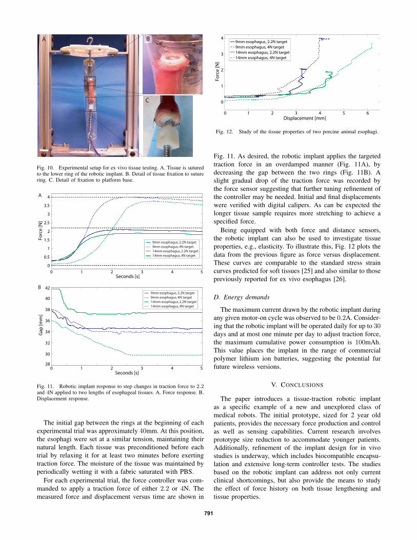
In these experiments, fresh porcine esophagus (45kg ani-mal) was mounted to the implant as shown in Fig. 10. Twotissue samples were used with lengths of 45 and 60mm. Theinner and outer diameters of the two esophagi tissues were 9and 14mm, respectively, which are similar in size to a normalhuman esophagus in a 3 months old patient (10-12mm whendistended). Prior to experiments, the esophagus was keptin phosphate buffered saline (PBS) solution at 4◦ Celsius topreserve tissue properties. The esophagus tissue was mountedon the bottom suture ring of the robotic implant as shown.The tissue attachment was made using a horizontal runningsuture (4-0 Prolene sutures (Ethicon, Inc)), as shown inFig. 10B. The lower end of the esophagus was fixed to thebase of the testing platform through a modified eyebolt and“U” stiches (Fig. 10C). The total load on the suture ring,comprised of the tissue and the eyebolt was 18 and 21g.
790
A
C
B
Fig. 10. Experimental setup for ex vivo tissue testing. A. Tissue is suturedto the lower ring of the robotic implant. B. Detail of tissue fixation to suturering. C. Detail of fixation to platform base.
0 1 2 3 4 528
30
32
34
36
38
40
42
Seconds [s]
Ga
p [
mm
]
0 1 2 3 4 5
0
0.5
1
1.5
2
2.5
3
3.5
4
Seconds [s]
Fo
rce
[N
]
9mm esophagus, 2.2N target
9mm esophagus, 4N target
14mm esophagus, 2.2N target
14mm esophagus, 4N target
A
B9mm esophagus, 2.2N target
9mm esophagus, 4N target
14mm esophagus, 2.2N target
14mm esophagus, 4N target
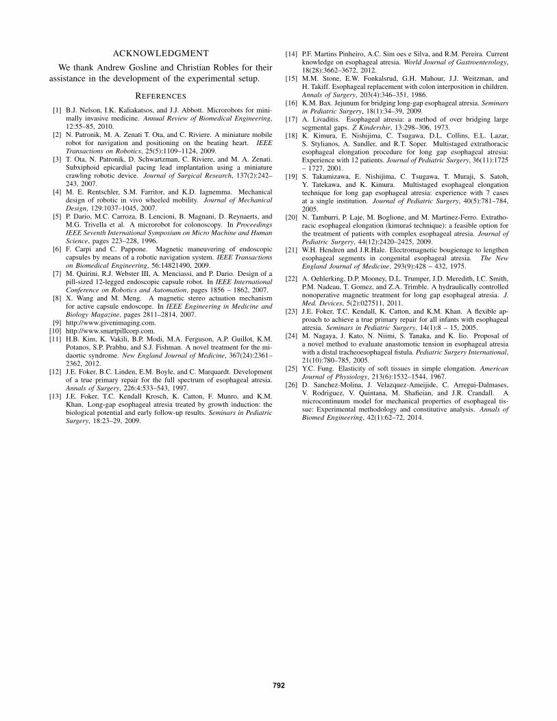
Fig. 11. Robotic implant response to step changes in traction force to 2.2and 4N applied to two lengths of esophageal tissues. A. Force response. B.Displacement response.
The initial gap between the rings at the beginning of eachexperimental trial was approximately 40mm. At this position,the esophagi were set at a similar tension, maintaining theirnatural length. Each tissue was preconditioned before eachtrial by relaxing it for at least two minutes before exertingtraction force. The moisture of the tissue was maintained byperiodically wetting it with a fabric saturated with PBS.
For each experimental trial, the force controller was com-manded to apply a traction force of either 2.2 or 4N. Themeasured force and displacement versus time are shown in
0 1 2 3 4 5 6
0
1
2
3
4
Displacement [mm]
Fo
rce
[N
]
9mm esophagus, 2.2N target
9mm esophagus, 4N target
14mm esophagus, 2.2N target
14mm esophagus, 4N target
Fig. 12. Study of the tissue properties of two porcine animal esophagi.
Fig. 11. As desired, the robotic implant applies the targetedtraction force in an overdamped manner (Fig. 11A), bydecreasing the gap between the two rings (Fig. 11B). Aslight gradual drop of the traction force was recorded bythe force sensor suggesting that further tuning refinement ofthe controller may be needed. Initial and final displacementswere verified with digital calipers. As can be expected thelonger tissue sample requires more stretching to achieve aspecified force.
Being equipped with both force and distance sensors,the robotic implant can also be used to investigate tissueproperties, e.g., elasticity. To illustrate this, Fig. 12 plots thedata from the previous figure as force versus displacement.These curves are comparable to the standard stress straincurves predicted for soft tissues [25] and also similar to thosepreviously reported for ex vivo esophagus [26].
D. Energy demands
The maximum current drawn by the robotic implant duringany given motor-on cycle was observed to be 0.2A. Consider-ing that the robotic implant will be operated daily for up to 30days and at most one minute per day to adjust traction force,the maximum cumulative power consumption is 100mAh.This value places the implant in the range of commercialpolymer lithium ion batteries, suggesting the potential furfuture wireless versions.
V. CONCLUSIONS
The paper introduces a tissue-traction robotic implantas a specific example of a new and unexplored class ofmedical robots. The initial prototype, sized for 2 year oldpatients, provides the necessary force production and controlas well as sensing capabilities. Current research involvesprototype size reduction to accommodate younger patients.Additionally, refinement of the implant design for in vivostudies is underway, which includes biocompatible encapsu-lation and extensive long-term controller tests. The studiesbased on the robotic implant can address not only currentclinical shortcomings, but also provide the means to studythe effect of force history on both tissue lengthening andtissue properties.
791
ACKNOWLEDGMENT
We thank Andrew Gosline and Christian Robles for theirassistance in the development of the experimental setup.
REFERENCES
[1] B.J. Nelson, I.K. Kaliakatsos, and J.J. Abbott. Microrobots for mini-mally invasive medicine. Annual Review of Biomedical Engineering,12:55–85, 2010.
[2] N. Patronik, M. A. Zenati T. Ota, and C. Riviere. A miniature mobilerobot for navigation and positioning on the beating heart. IEEETransactions on Robotics, 25(5):1109–1124, 2009.
[3] T. Ota, N. Patronik, D. Schwartzman, C. Riviere, and M. A. Zenati.Subxiphoid epicardial pacing lead implantation using a miniaturecrawling robotic device. Journal of Surgical Research, 137(2):242–243, 2007.
[4] M. E. Rentschler, S.M. Farritor, and K.D. Iagnemma. Mechanicaldesign of robotic in vivo wheeled mobility. Journal of MechanicalDesign, 129:1037–1045, 2007.
[5] P. Dario, M.C. Carroza, B. Lencioni, B. Magnani, D. Reynaerts, andM.G. Trivella et al. A microrobot for colonoscopy. In ProceedingsIEEE Seventh International Symposium on Micro Machine and HumanScience, pages 223–228, 1996.
[6] F. Carpi and C. Pappone. Magnetic maneuvering of endoscopiccapsules by means of a robotic navigation system. IEEE Transactionson Biomedical Engineering, 56:14821490, 2009.
[7] M. Quirini, R.J. Webster III, A. Menciassi, and P. Dario. Design of apill-sized 12-legged endoscopic capsule robot. In IEEE InternationalConference on Robotics and Automation, pages 1856 – 1862, 2007.
[8] X. Wang and M. Meng. A magnetic stereo actuation mechanismfor active capsule endoscope. In IEEE Engineering in Medicine andBiology Magazine, pages 2811–2814, 2007.
[9] http://www.givenimaging.com.[10] http://www.smartpillcorp.com.[11] H.B. Kim, K. Vakili, B.P. Modi, M.A. Ferguson, A.P. Guillot, K.M.
Potanos, S.P. Prabhu, and S.J. Fishman. A novel treatment for the mi-daortic syndrome. New England Journal of Medicine, 367(24):2361–2362, 2012.
[12] J.E. Foker, B.C. Linden, E.M. Boyle, and C. Marquardt. Developmentof a true primary repair for the full spectrum of esophageal atresia.Annals of Surgery, 226:4:533–543, 1997.
[13] J.E. Foker, T.C. Kendall Krosch, K. Catton, F. Munro, and K.M.Khan. Long-gap esophageal atresia treated by growth induction: thebiological potential and early follow-up results. Seminars in PediatricSurgery, 18:23–29, 2009.
[14] P.F. Martins Pinheiro, A.C. Sim oes e Silva, and R.M. Pereira. Currentknowledge on esophageal atresia. World Journal of Gastroenterology,18(28):3662–3672, 2012.
[15] M.M. Stone, E.W. Fonkalsrud, G.H. Mahour, J.J. Weitzman, andH. Takiff. Esophageal replacement with colon interposition in children.Annals of Surgery, 203(4):346–351, 1986.
[16] K.M. Bax. Jejunum for bridging long-gap esophageal atresia. Seminarsin Pediatric Surgery, 18(1):34–39, 2009.
[17] A. Livaditis. Esophageal atresia: a method of over bridging largesegmental gaps. Z Kindershir, 13:298–306, 1973.
[18] K. Kimura, E. Nishijima, C. Tsugawa, D.L. Collins, E.L. Lazar,S. Stylianos, A. Sandler, and R.T. Soper. Multistaged extrathoracicesophageal elongation procedure for long gap esophageal atresia:Experience with 12 patients. Journal of Pediatric Surgery, 36(11):1725– 1727, 2001.
[19] S. Takamizawa, E. Nishijima, C. Tsugawa, T. Muraji, S. Satoh,Y. Tatekawa, and K. Kimura. Multistaged esophageal elongationtechnique for long gap esophageal atresia: experience with 7 casesat a single institution. Journal of Pediatric Surgery, 40(5):781–784,2005.
[20] N. Tamburri, P. Laje, M. Boglione, and M. Martinez-Ferro. Extratho-racic esophageal elongation (kimuras technique): a feasible option forthe treatment of patients with complex esophageal atresia. Journal ofPediatric Surgery, 44(12):2420–2425, 2009.
[21] W.H. Hendren and J.R.Hale. Electromagnetic bougienage to lengthenesophageal segments in congenital esophageal atresia. The NewEngland Journal of Medicine, 293(9):428 – 432, 1975.
[22] A. Oehlerking, D.P. Mooney, D.L. Trumper, J.D. Meredith, I.C. Smith,P.M. Nadeau, T. Gomez, and Z.A. Trimble. A hydraulically controllednonoperative magnetic treatment for long gap esophageal atresia. J.Med. Devices, 5(2):027511, 2011.
[23] J.E. Foker, T.C. Kendall, K. Catton, and K.M. Khan. A flexible ap-proach to achieve a true primary repair for all infants with esophagealatresia. Seminars in Pediatric Surgery, 14(1):8 – 15, 2005.
[24] M. Nagaya, J. Kato, N. Niimi, S. Tanaka, and K. Iio. Proposal ofa novel method to evaluate anastomotic tension in esophageal atresiawith a distal tracheoesophageal fistula. Pediatric Surgery International,21(10):780–785, 2005.
[25] Y.C. Fung. Elasticity of soft tissues in simple elongation. AmericanJournal of Physiology, 213(6):1532–1544, 1967.
[26] D. Sanchez-Molina, J. Velazquez-Ameijide, C. Arregui-Dalmases,V. Rodriguez, V. Quintana, M. Shafieian, and J.R. Crandall. Amicrocontinuum model for mechanical properties of esophageal tis-sue: Experimental methodology and constitutive analysis. Annals ofBiomed Engineering, 42(1):62–72, 2014.
792