Embed Size (px)
Citation preview

www. .com
your reliable partner
K.856.V18.EN
ROBA-stop®-S

your reliable partner
ROBA-stop®-S have two functions. During standard operation they work as holding brakes. When the drives have been switched off, the brakes hold the system safely in position.During critical operational situations, e.g. with EMERGENCY STOP or power failure, ROBA-stop®-S are designed to absorb peak loads with high friction work. These brakes are designed for vertical and horizontal operations.
Dust and waterproofCompletely enclosed brake designcorresponds to Protection IP 67.
Permanent protectionagainst corrosionProtection IP 67, a high-qualitybrake body primary coating,chromed interior parts or use of stainless steel ensure protection against corrosion.
Easy handlingCompact construction and small outer diameters mean easy brake handling.
Minimum maintenanceexpenditureShould the friction linings be worn,just readjust the air gap or replacethe rotor with its friction linings.
Minimum operatingexpensesHigh working reliability and lowmaintenance expenditure reducethe operating expenses of thebrake to a minimum.
Condensation waterinspectionRegular inspection is possible via a drain plug.
RectifierA rectifier integrated in the terminalbox allows a brake connection toAC-supply. The magnetic coil isdesigned as a DC-coil.
Wear monitoringAn additional microswitch can beinstalled into the ROBA-stop®-Swhich monitors the wear onthe friction linings.
Brake housing andintegral terminal boxThe one-piece cast iron housingwith integrated terminal box isextremely robust and, therefore,protected against mechanicaldamages.
Anti-condensation heatingThe heater avoids condensationwater inside the brake. This usageis especially recommendedat temperatures under zero degreesCelsius or in high air humidity.
Braking torqueBy changing the number of springs,the braking torque can be adapted tothe system-specific requirements.
Optimum protection forelectrical equipmentThe electrical supply and the inspection and monitoring functionmicroswitches are completelyprotected inside the cast terminal box.
Release monitoringThe ROBA-stop®-S is fittedwith a microswitch for releasemonitoring. The microswitch emits asignal when the brake is opened.
Tacho attachmentThe brake body can be fitted with a tacho attachment. If no tacho is used, the coil carrier is closed by a cover.
Emergency hand releaseThe sea water brake is fittedwith an emergency hand release.The brake can be released mechanically via two screws (bracket hand release available on request).
Inspection withoutsystem downtimesA threaded hole allows fast inspection of the air gap without dismantling the brake.
Motors withself-ventilationIn order to assemble theROBA-stop®-S onto motors with continuous shafts on the B-bearing side, the closed standard cover on the brake rear side is exchanged for the open cover with integrated radial shaft sealing ring.
2

C USLR 108927
your reliable partner
Quality, Experience, Competence
3

L2
z1
v
h1
Ø M
1
Ø Z
1 H
8
Ø V
Ø s
1
N
Ø D
H
M20x1,5M20x1,5 L
l
z
L1
l1
l2
Ø M
Ø Z
H8
Ø d
max
Ø s
L3
l3
z
ØZ
F6
Ød 1
k2
Ød
h
ØM
2
s 2
L4
l1
l ØD
N
H
M20x1,5M20x1,5
ØD
1
ØZ
F6
z
k
ØM
s
your reliable partner
View without flange plate
Size ØD H h1 L L1 L2 l 1) l1 l2 ØM ØM1 N s s1 ØV v Z Z1 z z1
8 240 155 10 143,5 118 108 35 12 4 100 100 109 6 x ø9 M6 46 6,5 130 85 5 5,5
9 270 167 10 138,5 128,5 118,5 35 18 4 110 100 109 8 x ø9 M6 50 6,5 140 85 5 6
10 310 185 10 152,0 148 138 50 21-10 4 128 100 109 8 x ø11 M6 66 2,0+10 160 85 5 9
Size Ød1 ØD ØD1 H h k k2 L3 L4 l 1) l1 l3 ØM ØM2 N s s2 Z z
11 150 450 435 217 25 24 17,5 169,1 194,1 115 40,8 10 400 400 106 6 x M12 8 x M16 350 6
Dimensions [mm]
Bores Ødmin 1) Ødmax
1)
Size DIN 6885/1 DIN 6885/1 DIN 6885/3
11 55 75 -
Bores Ødmin 1) Ødmax
1)
Size DIN 6885/1 DIN 6885/1 DIN 6885/3
8 25 45 -
9 25 47 50
10 25 57 60
Sizes 8 – 10
Size 11
1) Please observe load on shaft or key!4

your reliable partner
Order Number – Sizes 8 - 10
__ / 8 5 6 . 4 1 7 . __ / __ / __ / __
Size 8910
Terminal box: with terminalwith half-wave rectifier
with bridge rectifier
145
Voltage * [VDC] ± 10 %
24104180207
Bore Ø d H7
(Dimensionspage 4)
Keyway acc.
DIN 6885/1 or
DIN 6885/3Options: - Anti-condensation heating
- Microswitch for wear monitoring- Other Types available on request
Example: 9 / 856.417.4 / 104 / 30 / 6885/1
Technical DataSize
8 9 10 11
Braking torque 2) M1 [Nm] 100 200 400 800
Max. speed nmax [rpm] 3400 3000 3000 3000
Input powerP20 [W] 85 100 120 268
ACH 3) [W] 15 15 21 on request
Moment of inertia rotor and hub for dmax.. I [10-4 kgm2] 17,9 33,7 84,8 360,6
Tightening torque fixing screwss [Nm] 23 23 46 61
s2 [Nm] - - - 122
Friction work
per 0,1 mm wear Q0,1 [J] 44 x 106 54,5 x 10⁶ 70 x 106 95 x 106
up to re-adjustment QN [J] 132 x 106 272 x 106 420 x 106 475 x 106
up to wear on rotor Qtot. [J] 308 x 106 545 x 106 770 x 106 1900 x 106
Weightwith flange plate [kg] 19 26 42 95
without flange plate [kg] - - - 86
Technical Data and Order Number
Order Number – Size 11
__ / 8 5 6 . 4 1 __ . __ / __ / __ / __
Size 11
Additional parts: without additional partsflange plate
flange plate + wear monitoringwear monitoring
3568
Voltage ** [VDC] ± 10 %
104180207
Bore Ø d H7
(Dimensionspage 4)
Keyway acc.
DIN 6885/1
Terminal box: with terminalwith half-wave rectifier
with bridge rectifier
145
Options: - Anti-condensation heating - Tacho attachment possible- Other Types available on request
Example: 11 / 856.411.5 /180 / 60 / 6885/1
** Standard voltages [VDC]: 104; 180; 207. Permitted voltage tolerance ± 10 % according to DIN IEC 60038.
2) Tolerance = + 40 % / - 20 %. Other braking torques available on request. 3) ACH = Anti-condensation heating, standard voltages [VAC]: 115; 230.
* Standard voltages [VDC]: 24; 104; 180; 207. Permitted voltage tolerance ± 10 % according to DIN IEC 60038.
On request ROBA-stop®-S brakes can also be delivered with UL approval.
According to German notation, decimal points in this document are represented with a comma (e.g. 0,5 instead of 0.5).We reserve the right to make dimensional and constructional alterations.
E1897285

100
1 000
10 000
100 000
1 000 000
1 10 100 1 000
your reliable partner
Friction Power Diagrams
Diagram 1: ROBA-stop®-S Sizes 8 - 10 / Type 856.417._
Conditions:
Speed: 1750 rpmBrake 100% duty cycle.
Mounting brake without cooling current.
Ambient temperature: 60 °C
Sh Switching frequency [1/h]
Qpe
rm P
erm
itted
fric
tion
wor
k [J
] Size 10
Size 9
Size 8
For higher speeds than 1750 rpm (Sizes 8 – 10): Please contact the manufacturers for information on the permitted friction work Qperm.!
Permitted Brake Friction Work
The permitted friction work dependent on the switching frequency, as shown in the characteristic curves (pages 6 and 7) must not be exceeded. Diagrams 1 and 2 show the permitted friction work Qperm for the various brake sizes and speeds (1750 rpm with brake Sizes 8 – 10 and 1000 rpm with brake Size 11) with reference to the switching frequency on which it is based.
6

100 000
1 000 000
0
50 000
100 000
150 000
200 000
250 000
300 000
350 000
400 000
450 000
500 000
300 000
101 100
1 000 1 500 2 000 2 500 0 100 3 000 1 250
3,510 000
your reliable partner
Conditions:
Speed: 1000 rpm At higher speeds, the friction work reduces acc. diagram 3.
Brake 100% duty cycle.
Mounting brake without cooling current.
Sh Switching frequency [1/h]
Qpe
rm P
erm
itted
fric
tion
wor
k [J
]
For higher speeds than 1000 rpm (Size 11): Please observe diagram 3!
Design example for a speed of 1250 rpm:
Permitted friction work Qperm for 1250 rpm from diagram 3: 300 000 J.This value limits the permitted friction work Qperm acc. diagram 2 for low switching frequencies (here up to 3,5 switchings per hour). The permitted friction work Qperm reduces acc. diagram 2 with higher switching frequencies.
Qpe
rm P
erm
itted
fric
tion
wor
k [J
]
n Speed [rpm]
Diagram 2: ROBA-stop®-S Size 11 / Type 856.417._
Diagram 3: ROBA-stop®-S Size 11 / Type 856.417._
Size 11
7
24 6 19 20 3.1
12
25 15 14
26
10
10
13
26
3 5 1 2
17
18
16
22
23
421/21.1
9 8 7 11 10
4
1
5
16.1
28/28.1
22 32 31 33
2
24
15
6.1
1427
18
17/20
10
34 26
30
25
29
10
10
6.2
117.1 10
12/13
your reliable partner
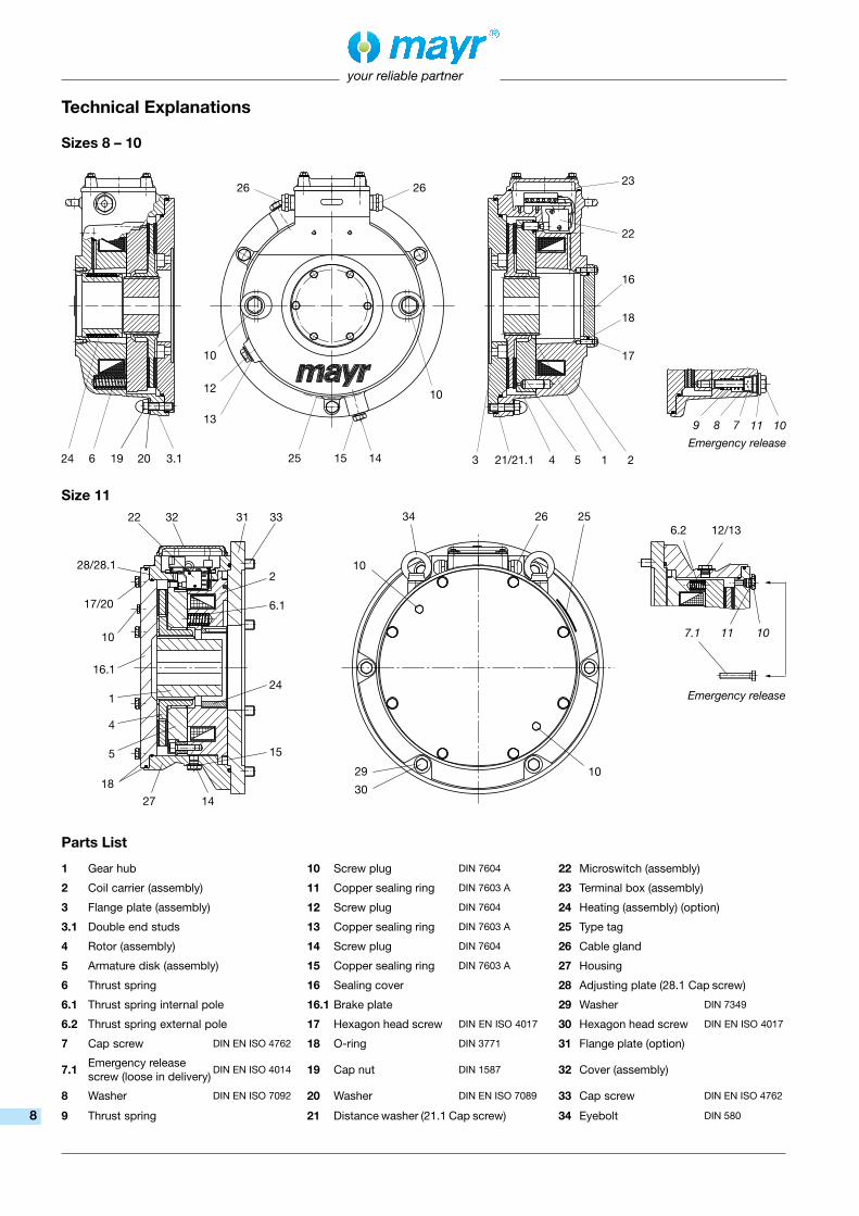
Technical Explanations
Emergency release
Sizes 8 – 10
Size 11
Parts List
1 Gear hub 10 Screw plug DIN 7604 22 Microswitch (assembly)
2 Coil carrier (assembly) 11 Copper sealing ring DIN 7603 A 23 Terminal box (assembly)
3 Flange plate (assembly) 12 Screw plug DIN 7604 24 Heating (assembly) (option)
3.1 Double end studs 13 Copper sealing ring DIN 7603 A 25 Type tag
4 Rotor (assembly) 14 Screw plug DIN 7604 26 Cable gland
5 Armature disk (assembly) 15 Copper sealing ring DIN 7603 A 27 Housing
6 Thrust spring 16 Sealing cover 28 Adjusting plate (28.1 Cap screw)
6.1 Thrust spring internal pole 16.1 Brake plate 29 Washer DIN 7349
6.2 Thrust spring external pole 17 Hexagon head screw DIN EN ISO 4017 30 Hexagon head screw DIN EN ISO 4017
7 Cap screw DIN EN ISO 4762 18 O-ring DIN 3771 31 Flange plate (option)
7.1 Emergency release screw (loose in delivery)
DIN EN ISO 4014 19 Cap nut DIN 1587 32 Cover (assembly)
8 Washer DIN EN ISO 7092 20 Washer DIN EN ISO 7089 33 Cap screw DIN EN ISO 4762
9 Thrust spring 21 Distance washer (21.1 Cap screw) 34 Eyebolt DIN 580
Emergency release
8

your reliable partner
DesignStandard
• Release monitoring• Emergency hand release• Terminal block• Condensation drain screw• Air gap inspection hole• Protection IP 67• Corrosion protection
Options
• Wear monitoring• Bracket hand release• Built-in rectifier• Anti-condensation heating• Tacho attachment possibility (standard on Sizes 8 – 10)• Available without flange plate
(only on Size 11)
Installation ConditionsThe following points must be observed before installing the ROBA-stop®-S:
- The eccentricity of the shaft end in relation to the mounting pitch circle must not exceed 0,4 mm.
- The run-out deviation of the screw-on surface to the shaft must not exceed the permitted run-out tolerance according to DIN 42955. Larger deviations can lead to a drop in torque, to continuous slipping on the rotor and to overheating.
- The rotor and brake surfaces must be oil and grease-free.
Brake InstallationPlease find a detailed installation description in the Installation and Operational Instructions for each product.
Sizes 8 – 10:
1) Loosen the cap nuts (19) and remove the washers (20).2) Remove the flange plate (3) from the brake by lightly beating on
the double end studs (3.1) with a plastic hammer.3) Screw the flange plate (3) onto the machine wall (must be
sealed customer-side; if you have any questions concerning the sealing, please contact the manufacturer).
4) Mount the gear hub (1) onto the shaft and secure it axially.5) Push the rotor (4) onto the gear hub (1) by hand. 6) Push the brake over the double end studs (3.1) and arrange it
on the flange plate (3).7) Screw on the brake with the cap nuts (19) and the washers (20)
placed under them.8) Screw out the screw plugs (10) incl. copper sealing rings (11).9) Screw out both emergency release screws (7) from the armature
disk (5).10) Screw in the screw plugs (10) with the copper sealing rings
(11) again, whereby the emergency release screws (7) are to be spring-contacted.
11) Check the air gap: 0,2 on Size 8; 0,25 on Sizes 9 – 10.
Size 11:
1) Only for designs with flange plate (Item 31/option): Loosen the hexagon head screws (30) and remove the flange plate from the brake. Screw the flange plate to the machine wall using the cap screws (33) (must be sealed customer-side).
2) Remove the brake plate (16.1) by loosening the hexagon head screws (17).
3) Remove the rotor (4) from the brake.4) Mount the gear hub (1) onto the shaft and secure it axially.5) Screw the brake onto the flange plate (31) or a customer-side
brake surface.6) Push the rotor (4) onto the gear hub (1) by hand. 7) Mount the brake plate (16.1), observe the correct angular
position of the emergency release. 8) Check the air gap: 0,45 on Size 11.
Braking Torque AdjustmentThe ROBA-stop®-S are set manufacturer-side to the nominal torque or the braking torque requested on order. In order to reduce the braking torque, the brake must be dismantled and the thrust springs must be removed. This prevents unintended or unpermitted external torque adjustment.
Braking torque adjustment takes place via different configuration variants of the thrust springs in the coil carrier.
Sizes 8 – 10:
Two springs (6) lying opposite each other must always be removed or inserted to make sure that the armature disk (5) is evenly loaded.
Size 11:
Braking torque adjustment takes place by evenly removing or inserting thrust springs (6.1 and 6.2) on the internal and external pole of the coil carrier (2).
Air Gap InspectionThe nominal air gap between the armature disk (5) and the coil carrier (2) is set manufacturer-side to 0,2 on Size 8, to 0,25 on Sizes 9 – 10 and to 0,45 on Size 11. However, the air gap between the armature disk (5) and the coil carrier (2) is increased due to wear on the friction linings. The wear condition of the rotor (4) must be monitored by regular air gap inspections. Only carry out air gap inspections on a de-energised brake!
1) Unscrew the screw plug (12) incl. copper sealing ring (13).
2) Check the air gap by means of a feeler gauge. The air gap must lie between the nominal air gap and the max. air gap. (Max. air gap: Size 8 = 0,75; Size 9 = 1,0; Size 10 = 1,1; Size 11 = 1,65 – values refer to the nominal braking torque). If the max. air gap is reached, re-adjust the air gap.
Air Gap Re-adjustment
Sizes 8 – 10:
The air gap can be re-adjusted once by removing the distance rings (21) between the flange plate (3) and the coil carrier (2).
1) Unscrew the screw plugs (10) incl. copper sealing rings (11).2) Screw in both emergency release screws (7) evenly until they
contact the coil carrier (2).3) Loosen the cap nuts (19) with washers (20).4) Remove the brake from the flange plate (3).5) Unscrew the distance washers (21) from the flange plate (3). 6) Push the brake over the double end studs (3.1) and set it on the
flange plate (3).7) Screw on the brake using the cap nuts (19) or the washers (20).8) Procedure as described in “Brake Installation, Sizes 8 – 10”,
according to points 9) – 11).If the air gap exceeds the max. values again and the distance washers (21) have already been removed, the rotor (4) must be replaced.
Size 11:
The air gap can be re-adjusted twice. This is carried out by removing one layer of the adjusting plate (28) on the housing (27).1) Remove the brake plate (16.1) by loosening the hexagon head
screws (17).2) Loosen the cap screws (28.1), remove one layer of the adjusting
plate (28). Tighten the cap screws (28.1).3) Procedure as described in “Brake Installation, Size 11”, according
to points 7) – 8).
If the max. air gap is reached again, the rotor (4) must be replaced.Please keep a replacement rotor in stock in order to avoid system downtimes.
9

your reliable partner
Replacing Worn PartsThe rotor (4), the armature disk (5) and the gear hub (1) are parts which are subject to wear.
1) At first, please follow the same procedure as in “Air Gap Re-Adjustment”:
- Sizes 8 – 10 according to points 1 – 4 - Size 11 according to point 12) Check the parts subject to wear and replace them if necessary.
• Replacing the rotor: - Size 11: Attach the adjusting plate (28) to the housing (27) using
the cap screws (28.1). (Adjusting plate and cap screws are part of the replacement rotor delivery).
- Sizes 8 – 11: Replace the rotor (4). - Sizes 8 – 10: Screw the distance rings (21) onto the flange plate
(3) using the cap screws (21.1). (Distance washers and cap screws are part of the replacement rotor delivery).
3) Mount the brake according to “Brake Installation”: - Sizes 8 – 10 according to points 6 – 7 and points 9 – 10 - Size 11 according to point 74) Check the air gap.
Release MonitoringThe ROBA-stop®-S is equipped with a microswitch for release monitoring as part of the standard delivery. It emits a signal when the brake is opened. The microswitch is completely enclosed inside the terminal box. It can easily be replaced, re-adjusted and tested by removing the terminal box cover and the terminal block/rectifier.
Wear Monitoring (Option)An additional microswitch for wear monitoring can be integrated into the ROBA-stop®-S. It emits a signal before the max. permitted wear is exceeded.
Anti-Condensation Heating (Option)The ROBA-stop®-S can be equipped with an anti-condensation heating. An AC coil installed inside the brake prevents condensation and its consequences. Please Observe!The projecting key must not collide with the heating.
Condensation Drain ScrewCondensation water draining can be carried out via the drain screw (14) at the bottom of the brake. The hole is normally closed.
Emergency ReleaseIn case of a malfunction or power failure, the brake remains closed and cannot be released electrically. In this case, a manual emergency release can be carried out.
• Unscrew the screw plugs (10) with the copper sealing rings (11).• - Sizes 8 – 10: Screw both emergency release screws (7) evenly
into the armature disk (5).- Size 11: Screw in both emergency release screws (7.1) evenly.
• The brake is released and the rotor is free.
Electrical ConnectionThe ROBA-stop®-S is equipped with a DC coil. Inside the terminal box, a terminal block or rectifier is installed.
10

your reliable partner
Protection IP67: Dust-proof and protected against contact as well as against temporary immersion in water.
Intended Usemayr® brakes have been developed, manufactured and tested in compliance with the VDE 0580 standard, in accordance with the EU Low Voltage Directive. During installation, operation and maintenance of the product, the standard requirements must be observed. mayr® brakes are for use in machines and systems and must only be used in the situations for which they are ordered and confirmed. Using them for any other purpose is not allowed!
Guidelines for Electromagnetic Compatibility (EMC)In accordance with the EMC Directives 2004/108/EC, the individual components produce no emissions. However, functional components e.g. mains-side energisation of the brakes with rectifiers, phase demodulators, ROBA®-switch devices or similar controls can produce disturbance which lies above the allowed limit values. For this reason it is important to read the Installation and Operational Instructions very carefully and to keep to the EMC Directives.
Regulations, Standards and Directives UsedVDE 0580 Electromagnetic devices and components, general directives2006/95/EC Low voltage directiveCSA C22.2 No. 14-2010 Industrial Control EquipmentUL 508 (Edition 17) Industrial Control EquipmentEN ISO 12100 Safety of machinery - General principles - Risk assessment and risk reductionEN 61000-6-4 Interference emissionEN 61000-6-2 Interference immunityEN 60204-1 Electrical machine equipment
Liability• The information, guidelines and technical data in these documents
were up to date at the time of printing. Demands on previously delivered brakes are not valid.
• Liability for damage and operational malfunction will not be taken when - the Installation and Operational Instructions are ignored or
neglected.- the brakes are used inappropriately.- the brakes are modified.- the brakes are worked on unprofessionally.- the brakes are handled or operated incorrectly.
Guarantee• The guarantee conditions correspond with the Chr. Mayr GmbH +
Co. KG sales and delivery conditions.• Mistakes or deficiencies are to be reported to mayr® at once!
Safety GuidelinesBrakes may generate, among other things, the following risks:
Contact with voltage- carrying
components
Contact with hot surfaces
Hand injuries
Danger of seizure
Magnetic fields
During the required risk assessment when designing the machine or system, the dangers involved must be evaluated and removed by taking appropriate protective measures. To prevent injury or damage, only professionals and specialists should work on the devices. They must be familiar with the dimensioning, transport, installation, initial operation, maintenance and disposal according to the relevant standards and regulations.
Application Conditions
The catalogue values are guideline values which have been determined in test facilities. It may be necessary to carry out your own tests for the intended application. When dimensioning the brakes, please remember that installation situations, braking torque fluctuations, permitted friction work, run-in behaviour and wear as well as general ambient conditions can all affect the given values. These factors should therefore be carefully assessed, and alignments made accordingly.
r Mounting dimensions and connecting dimensions must be adjusted according to the size of the brake at the place of installation.
r The magnetic coils are designed for a relative duty cycle of 100 %, if no other values are stated.
r The braking torque is dependent on the present run-in condition of the brakes.
r The brakes are only designed for dry running. The torque is lost if the friction surfaces come into contact with oil, grease, water or similar substances, as well as other foreign substances.
r Manufacturer-side corrosion protection of the metallic surfaces. r The rotors may rust up and block in corrosive ambient conditions
and/or after long periods of storage.
Ambient Temperature - 20 °C up to + 40 °C
Earthing Connection The brake is designed for Protection Class I. This protection covers not only the basic insulation, but also the connection of all conductive parts to the PE conductor on the fixed installation. If the basic insulation fails, no contact voltage will remain. Please carry out a standardized inspection of the PE conductor connections to all contactable metal parts!
Guidelines on the Declaration of Conformity: A conformity evaluation has been carried out for the product (electromagnetic safety brake) according to the EC Low Voltage Directive 2006/95/EC. The conformity evaluation is set out in writing in a separate document and can be requested if required.
Guidelines on the EMC Directive (2004/108/EC): The product cannot be operated independently according to the EMC Directive. Due to their passive state, brakes are also non-critical equipment according to the EMC. Only after integration of the product into an overall system can this be evaluated in terms of the EMC. For electronic equipment, the evaluation has been verified for the individual product in laboratory conditions but not in the overall system.
Guidelines on the Machinery Directive (2006/42/EC): The product is a component for installation into machines according to the Machinery Directive 2006/42/EC. The brakes can fulfil the specifications for safety-related applications in coordination with other elements. The type and scope of the required measures result from the machine risk analysis. The brake then becomes a machine component and the machine manufacturer assesses the conformity of the safety unit to the directive. It is forbidden to put the product into initial operation until it has been ensured that the machine accords with the stipulations in the directive.
Guidelines on the ATEX Directive: Without a conformity evaluation, this product is not suitable for use in areas where there is a high danger of explosion. In order to use this product in areas where there is a danger of explosion, classification and marking according to the directive 94/9/EC must be carried out.
11

Representatives
More representatives:
Austria, Belgium, Brazil, Canada, Denmark, Finland, Greece, Hongkong, Hungary, Indonesia, Israel, Luxembourg, Malaysia, New Zealand, Norway, Philippines, Romania, Russia, Slovakia, Slovenia, South Africa, Spain, Sweden, Thailand, TurkeyYou can find the complete address for the representative responsible for your area under www.mayr.com in the internet.
Headquarters
Chr. Mayr GmbH + Co. KGEichenstraße 1, D-87665 MauerstettenTel.: +49 83 41/8 04-0, Fax: +49 83 41/80 44 21www.mayr.com, E-Mail: [email protected]
Branch office
Service Germany
Baden-WürttembergEsslinger Straße 770771 Leinfelden-EchterdingenTel.: 07 11/45 96 01 0Fax: 07 11/45 96 01 10
BavariaEichenstraße 187665 MauerstettenTel.: 0 83 41/80 41 04Fax: 0 83 41/80 44 23
ChemnitzBornaer Straße 20509114 ChemnitzTel.: 03 71/4 74 18 96Fax: 03 71/4 74 18 95
FrankenUnterer Markt 991217 HersbruckTel.: 0 91 51/81 48 64Fax: 0 91 51/81 62 45
KamenLünener Straße 21159174 KamenTel.: 0 23 07/23 63 85Fax: 0 23 07/24 26 74
NorthSchiefer Brink 832699 ExtertalTel.: 0 57 54/9 20 77Fax: 0 57 54/9 20 78
Rhine-MainHans-Böckler-Straße 664823 Groß-Umstadt Tel.: 0 60 78/7 82 53 37Fax: 0 60 78/9 30 08 00
ChinaMayr ZhangjiagangPower Transmission Co., Ltd. Fuxin Road No.7, Yangshe Town215637 ZhangjiagangTel.: 05 12/58 91-75 67Fax: 05 12/58 91-75 [email protected]
Great BritainMayr Transmissions Ltd.Valley Road, Business ParkKeighley, BD21 4LZWest YorkshireTel.: 0 15 35/66 39 00Fax: 0 15 35/66 32 [email protected]
FranceMayr France S.A.S.Z.A.L. du MinopoleRue Nungesser et Coli62160 Bully-Les-MinesTel.: 03.21.72.91.91Fax: [email protected]
ItalyMayr Italia S.r.l.Viale Veneto, 335020 Saonara (PD)Tel.: 0498/79 10 20Fax: 0498/79 10 [email protected]
SingaporeMayr Transmission (S) PTE Ltd.No. 8 Boon Lay Way Unit 03-06, TradeHub 21Singapore 609964 Tel.: 00 65/65 60 12 30Fax: 00 65/65 60 10 [email protected]
SwitzerlandMayr Kupplungen AGTobeläckerstraße 118212 Neuhausen am RheinfallTel.: 0 52/6 74 08 70Fax: 0 52/6 74 08 [email protected]
USAMayr Corporation10 Industrial AvenueMahwahNJ 07430Tel.: 2 01/4 45-72 10Fax: 2 01/4 45-80 [email protected]
AustraliaRegal Beloit Australia Pty Ltd.19 Corporate Ave03178 Rowville, VictoriaAustralienTel.: 0 3/92 37 40 00Fax: 0 3/92 37 40 [email protected]
IndiaNational EngineeringCompany (NENCO)J-225, M.I.D.C. Bhosari Pune 411026Tel.: 0 20/27 13 00 29Fax: 0 20/27 13 02 [email protected]
JapanMATSUI Corporation2-4-7 AzabudaiMinato-kuTokyo 106-8641Tel.: 03/35 86-41 41Fax: 03/32 24 24 [email protected]
NetherlandsGroneman BV Amarilstraat 117554 TV Hengelo OVTel.: 074/2 55 11 40Fax: 074/2 55 11 [email protected]
PolandWamex Sp. z o.o. ul. Pozaryskiego, 2804-703 WarszawaTel.: 0 22/6 15 90 80Fax: 0 22/8 15 61 [email protected]
South KoreaMayr Korea Co. Ltd.15, Yeondeok-ro 9beon-gilSeongsan-gu51571 Changwon-siGyeongsangnam-do. KoreaTel.: 0 55/2 62-40 24Fax: 0 55/2 62-40 [email protected]
TaiwanGerman Tech Auto Co., Ltd.No. 28, Fenggong Zhong Road, Shengang Dist.,Taichung City 429, Taiwan R.O.C.Tel.: 04/25 15 05 66Fax: 04/25 15 24 [email protected]
Czech RepublicBMC - TECH s.r.o.Hviezdoslavova 29 b62700 BrnoTel.: 05/45 22 60 47Fax: 05/45 22 60 [email protected]
HagenIm Langenstück 658093 HagenTel.: 0 23 31/78 03 0Fax: 0 23 31/78 03 25
your reliable partner
16/1
2/20
16 S
C/G
F