Embed Size (px)
Citation preview
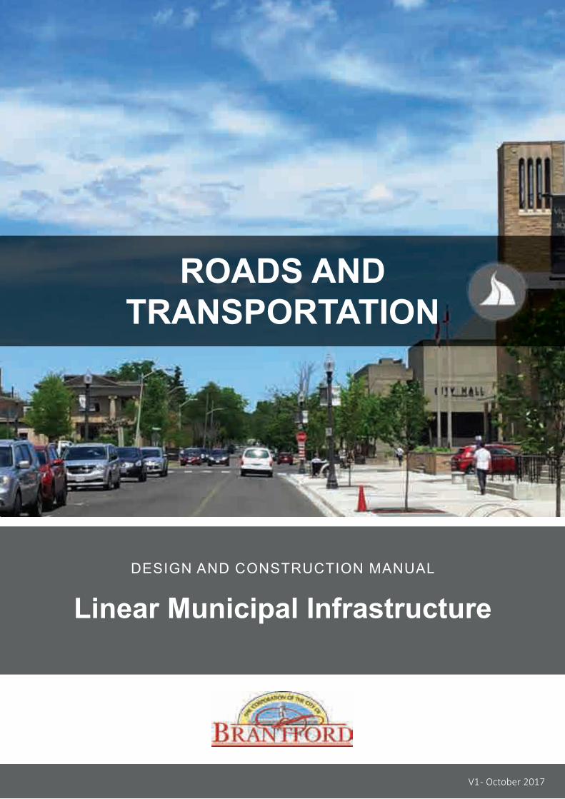
ROADS ANDTRANSPORTATION
DESIGN AND CONSTRUCTION MANUAL
Linear Municipal Infrastructure
V1 - October 2017

Roads and TransportationExisting Version New Version New (N); Revised (Rev); Cancelled (C); Reissued (R)
October 2017 N: V1 – Original Final Submission
REVIS ION TRACKING
TABLE OF CONTENTS
V1 - October 2017 i
12333
4555
677788888
101111111112
121212
1414141515
INTRODUCTION1.0 General Requirements2.0 Other Reference Documents3.0 Industry Standards and Specifications4.0 Other Applicable Acts and Legislations
DESIGN5.0 General6.0 Road Classifications
6.1 Classifications
7.0 Roadway Cross-Sections8.0 Geometric Design Elements9.0 Intersections10.0 Cul-de-Sacs11.0 Location of Utilities12.0 Bike Lanes13.0 Pavement Design
13.1 General Requirements13.2 Alternative Materials
14.0 Concrete Curb15.0 Subdrains16.0 Driveway and Driveways Approaches
16.1 General Requirements16.2 Driveway Design16.3 Curb Depression
17.0 Roundabouts17.1 General Requirements17.2 Initial Assessment
18.0 Pedestrian Ways18.1 General Requirements18.2 Sidewalks18.3 Multi-Use Trails18.4 Tactile Surface Warning Plates
TABLE OF CONTENTS
V1 - October 2017 ii
19.0 Bus Stops and Shelters20.0 Traffic Control
20.1 General Requirements20.2 Traffic Control Signs20.3 Intersection Pedestrian Signals20.4 Electrical Design20.5 Pavement Design20.6 Traffic Calming Measures
21.0 Street Lighting21.1 General Requirements21.2 Photometric Plan Submission Requirements21.3 Pole Types21.4 Light Types
22.0 Street Signs22.1 General Requirements
23.0 Parking24.0 Street Trees
24.1 General Requirements24.2 Spacing and Buffers24.3 Tree Species24.4 Topsoil, Seed and Sod
25.0 Boulevard Design26.0 Fences and Walls
26.1 Fences26.2 Noise Attenuation Walls26.3 Retaining Walls
1516161616161616
1717171717
1818
181818191919
2021212121
V1 - October 2017 iii
TABLE OF CONTENTS
22232627272828292930313140404547484950
5161
CONSTRUCTIONSPECIAL PROVISIONS - GENERAL27.0 Asphalt Work28.0 Pavement Markings29.0 Granular Material30.0 Concrete Curb31.0 Subdrain32.0 Asphalt Driveways33.0 Concrete Driveways34.0 Replacement of Existing Paving Stone35.0 Sidewalks and Multi-use Trail36.0 Tactile Warning Surfaces37.0 Traffic Signals38.0 Traffic Sign39.0 Topsoil and Sod40.0 Topsoil and Seed41.0 Plantings42.0 Remove and Replace Fences43.0 Retaining Wall44.0 Adjustment of Existing Appurtenances
TYPICAL RIGHT-OF-WAY CROSS SECTIONSSTANDARD DRAWINGS
L IST OF TABLES
TABLE 1 Street Classifications.................................................................
TABLE 2 Geometric Design Elements........................................................
TABLE 3 Minimum Pavement Design Requirements for Local Roads...........
TABLE 4 Minimum Pavement Design Requirements for Collector Roads......
TABLE 5 Minimum Pavement Design Requirements for Arterial Roads........
TABLE 6 Soil Classifications.....................................................................
TABLE 7 Driveway Requirements..............................................................
TABLE 8 Driveway / Curb Depression Widths............................................
TABLE 9 Concrete Sidewalk Requirements................................................
TABLE 10 Tree Spacing and Buffers...........................................................
TABLE 11 Asphalt Driveway Requirements..................................................
TABLE 12 Concrete Driveway Requirements................................................
TABLE 13 Bolt Size and Spacing for Pole Bases..........................................
TABLE 14 Traffic Signal Cable Colour Codes...............................................
TABLE 15 Wiring Chart..............................................................................
TABLE 16 Traffic Signal Head Colour Codes...............................................
TABLE 17 Pedestrian Signal Head Colour Codes.........................................
TABLE 18 Riser Cable Identification Chart..................................................
5
7
9
9
10
10
11
12
14
19
28
29
31
33
33
33
34
34
V1 - October 2017 iv
ROADS AND TRANSPORTATION
Introduction
V1 - October 2017 1
ROADS & TRANSPORTATIONINTRODUCTION
1.0 GENERAL REQUIREMENTS
This manual has been prepared to provide the City, consultanting engineers, contractors, developers and the general public with a common reference to ensure the consistent application of design and construction practices of road and related infrastructure within the City.
The information provided is not intended to hinder innovation and is rooted on meeting performance requirements over the lifecycle of the infrastructure. If deviating from the criteria and requirements set out in this manual, the Proponent shall provide justification for the change via a Standard Deviation Form (Appendix G-1 in the General Preface).
INTRODUCTION
The key guiding principles underlying this manual are to:
• Prioritize the health and safety of the public by providing accessible, safe and appealing options for travel around the City.
• Undertake sustainable planning, operation and maintenance of the road system, recognizing the important linkage to utilities and storm drainage infrastructure.
V1 - October 2017 2
ROADS & TRANSPORTATIONINTRODUCTION
3.0 INDUSTRY STANDARDS AND SPECIFICATIONS
All roads and transportation systems shall comply with the latest version of all applicable industry standards and specifications for quality management and quality control, including but not limited to the following:
• Electrical Safety Authority (ESA)
• Canadian Standards Association (CSA)
• American Society for Testing and Materials (ASTM)
4.0 OTHER APPLICABLE ACTS AND LEGISLATIONS
This manual does not supersede, nor replace any legislation governing the design and construction of road and transportation systems.
The Proponent shall be fully familiar with the latest version of these legislative requirements such when carrying out design and construction of City linear projects, such as:
• Ontario Highway Traffic Act, Municipal Act
• Ontario Water Resources Act
• Environmental Assessment Act
• Environmental Protection Act
• Accessibility for Ontarians with Disability Act (AODA)
2.0 OTHER REFERENCE DOCUMENTS
All roads and transportation systems shall be designed and constructed in accordance with the latest versions of this manual as well as other industry standards and best practices, including but not limited:
• Ontario Provincial Standard Specifications (OPSS) and Ontario Provincial Standard Drawings (OPSD)
• Geometric Design Guide for Canadian Roads prepared by the Transportation Association of Canada (TAC)
• Ontario Traffic Manual (OTM) prepared by the Ministry of Transportation (MTO)
• American Association of Transportation Highway Officials (AASHTO), latest edition
• Roadway Lighting ANSI / IES RP-8 prepared by the Illuminating Engineering Society of North America (IESNA), latest edition
• Guideline for Security Lighting for People, Property and Public Spaces, G-1-03 prepared by IESNA, latest edition
• Crime Prevention Through Environmental Design (CPTED)
• City of Brantford Facility Accessibility Design Standards
• City of Brantford Downtown Streetscape Design Plan
• City of Brantford Urban Design Guideline
• City of Brantford Traffic Signals Minimum Warrants for Installation Policy
• City of Brantford Traffic Calming Policy
• National Cooperative Highway Research Program (NCHRP), Report 672
V1 - October 2017 3

ROADS AND TRANSPORTATION
Design
V1 - October 2017 4
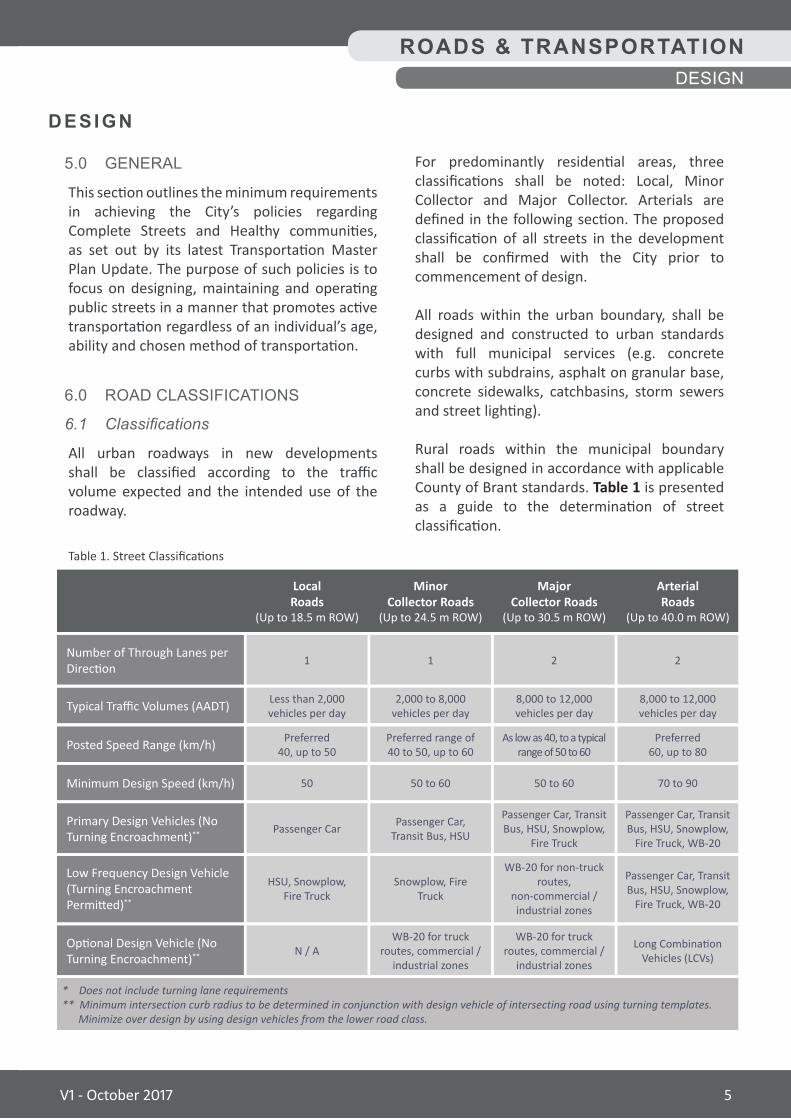
For predominantly residential areas, three classifications shall be noted: Local, Minor Collector and Major Collector. Arterials are defined in the following section. The proposed classification of all streets in the development shall be confirmed with the City prior to commencement of design.
All roads within the urban boundary, shall be designed and constructed to urban standards with full municipal services (e.g. concrete curbs with subdrains, asphalt on granular base, concrete sidewalks, catchbasins, storm sewers and street lighting).
Rural roads within the municipal boundary shall be designed in accordance with applicable County of Brant standards. Table 1 is presented as a guide to the determination of street classification.
5.0 GENERAL
This section outlines the minimum requirements in achieving the City’s policies regarding Complete Streets and Healthy communities, as set out by its latest Transportation Master Plan Update. The purpose of such policies is to focus on designing, maintaining and operating public streets in a manner that promotes active transportation regardless of an individual’s age, ability and chosen method of transportation.
6.0 ROAD CLASSIFICATIONS
6.1 Classifications
All urban roadways in new developments shall be classified according to the traffic volume expected and the intended use of the roadway.
DESIGN
Table 1. Street Classifications
LocalRoads
(Up to 18.5 m ROW)
1
Passenger Car
N / A
HSU, Snowplow, Fire Truck
Less than 2,000 vehicles per day
Preferred 40, up to 50
50
2
Passenger Car, Transit Bus, HSU, Snowplow,
Fire Truck
WB-20 for truck routes, commercial /
industrial zones
WB-20 for non-truck routes,
non-commercial /industrial zones
8,000 to 12,000vehicles per day
As low as 40, to a typical range of 50 to 60
50 to 60
1
Passenger Car, Transit Bus, HSU
WB-20 for truck routes, commercial /
industrial zones
Snowplow, Fire Truck
2,000 to 8,000vehicles per day
Preferred range of 40 to 50, up to 60
50 to 60
2
Passenger Car, Transit Bus, HSU, Snowplow,
Fire Truck, WB-20
Long Combination Vehicles (LCVs)
Passenger Car, Transit Bus, HSU, Snowplow,
Fire Truck, WB-20
8,000 to 12,000vehicles per day
Preferred 60, up to 80
70 to 90
Number of Through Lanes per Direction
Primary Design Vehicles (No Turning Encroachment)**
Optional Design Vehicle (No Turning Encroachment)**
Low Frequency Design Vehicle (Turning Encroachment Permitted)**
Typical Traffic Volumes (AADT)
Posted Speed Range (km/h)
Minimum Design Speed (km/h)
MinorCollector Roads
(Up to 24.5 m ROW)
MajorCollector Roads
(Up to 30.5 m ROW)
ArterialRoads
(Up to 40.0 m ROW)
* Does not include turning lane requirements** Minimum intersection curb radius to be determined in conjunction with design vehicle of intersecting road using turning templates. Minimize over design by using design vehicles from the lower road class.
ROADS & TRANSPORTATIONDESIGN
V1 - October 2017 5
ROADS & TRANSPORTATIONDESIGN
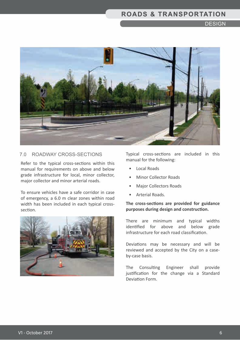
7.0 ROADWAY CROSS-SECTIONS
Refer to the typical cross-sections within this manual for requirements on above and below grade infrastructure for local, minor collector, major collector and minor arterial roads.
To ensure vehicles have a safe corridor in case of emergency, a 6.0 m clear zones within road width has been included in each typical cross-section.
Typical cross-sections are included in this manual for the following:
• Local Roads
• Minor Collector Roads
• Major Collectors Roads
• Arterial Roads.
The cross-sections are provided for guidance purposes during design and construction.
There are minimum and typical widths identified for above and below grade infrastructure for each road classification.
Deviations may be necessary and will be reviewed and accepted by the City on a case- by-case basis.
The Consulting Engineer shall provide justification for the change via a Standard Deviation Form.
V1 - October 2017 6
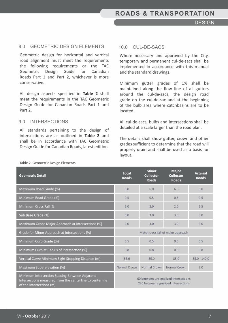
8.0 GEOMETRIC DESIGN ELEMENTS
Geometric design for horizontal and vertical road alignment must meet the requirements the following requirements or the TAC Geometric Design Guide for Canadian Roads Part 1 and Part 2, whichever is more conservative.
All design aspects specified in Table 2 shall meet the requirements in the TAC Geometric Design Guide for Canadian Roads Part 1 and Part 2.
9.0 INTERSECTIONS
All standards pertaining to the design of intersections are as outlined in Table 2 and shall be in accordance with TAC Geometric Design Guide for Canadian Roads, latest edition.
Table 2. Geometric Design Elements
LocalRoadsGeometric Detail
6.0
3.0
2.5
0.8
85.0 - 140.0
0.5
0.5
3.0
2.0
8.0
3.0
Match cross fall of major approach
2.0
0.8
85.0
0.5
0.5
3.0
Normal Crown
60 between unsignalized intersections240 between signalized intersections
6.0
3.0
2.0
0.8
85.0
0.5
0.5
3.0
Normal Crown
6.0
3.0
2.0
0.8
85.0
0.5
0.5
3.0
Normal Crown
Maximum Road Grade (%)
Maximum Grade Major Approach at Intersections (%)
Grade for Minor Approach at Intersections (%)
Minimum Cross Fall (%)
Minimum Curb at Radius of Intersection (%)
Vertical Curve Minimum Sight Stopping Distance (m)
Minimum Road Grade (%)
Minimum Curb Grade (%)
Sub Base Grade (%)
Maximum Superelevation (%)
Minimum Intersection Spacing Between Adjacent Intersections measured from the centerline to centerline of the intersections (m)
MinorCollector
Roads
MajorCollector
Roads
ArterialRoads
10.0 CUL-DE-SACS
Where necessary and approved by the City, temporary and permanent cul-de-sacs shall be implemented in accordance with this manual and the standard drawings.
Minimum gutter grades of 1% shall be maintained along the flow line of all gutters around the cul-de-sacs, the design road grade on the cul-de-sac and at the beginning of the bulb area where catchbasins are to be located.
All cul-de-sacs, bulbs and intersections shall be detailed at a scale larger than the road plan.
The details shall show gutter, crown and other grades sufficient to determine that the road will properly drain and shall be used as a basis for layout.
ROADS & TRANSPORTATIONDESIGN
V1 - October 2017 7
11.0 LOCATION OF UTILITIES
The location of all utilities within the road allowance shall in accordance with the Typical Cross-section in this manual and with the Utilities Design and Construction Manual.
12.0 BIKE LANES
Bike lane facilities shall be designed to the latest edition of TAC Bikeway Traffic Control Guidelines for Canada and Ontario Traffic Manual (OTM) Book 18.
Bike lanes shall be incorporated into all future minor collector / arterial roads and any such roads that are redesigned and repaved, if technically feasible.
Bike lanes will be incorporated onto major collector roads, where available space permits. Pavement structure for the on-street bike lanes are to be as per the required pavement structure for the class of road on which the bike lane is being constructed.
Refer to the Typical Cross-sections in this manual for further guidance on location. Bike lanes shall be 1.9 m wide. Signage and pavement markings are to be incorporated in accordance with TAC Bikeway Traffic Control Guidelines for Canada, latest edition.
Refer to the Ontario Traffic Manual (OTM) Book 18 for cycle track design.
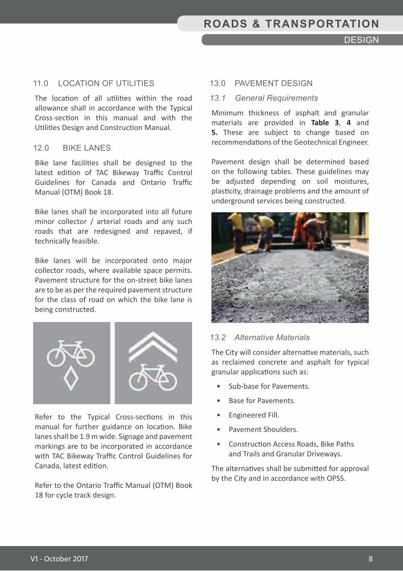
13.0 PAVEMENT DESIGN
13.1 GeneralRequirements
Minimum thickness of asphalt and granular materials are provided in Table 3, 4 and 5. These are subject to change based on recommendations of the Geotechnical Engineer.
Pavement design shall be determined based on the following tables. These guidelines may be adjusted depending on soil moistures, plasticity, drainage problems and the amount of underground services being constructed.
13.2 AlternativeMaterials
The City will consider alternative materials, such as reclaimed concrete and asphalt for typical granular applications such as:
• Sub-base for Pavements.
• Base for Pavements.
• Engineered Fill.
• Pavement Shoulders.
• Construction Access Roads, Bike Paths and Trails and Granular Driveways.
The alternatives shall be submitted for approval by the City and in accordance with OPSS.
ROADS & TRANSPORTATIONDESIGN
V1 - October 2017 8
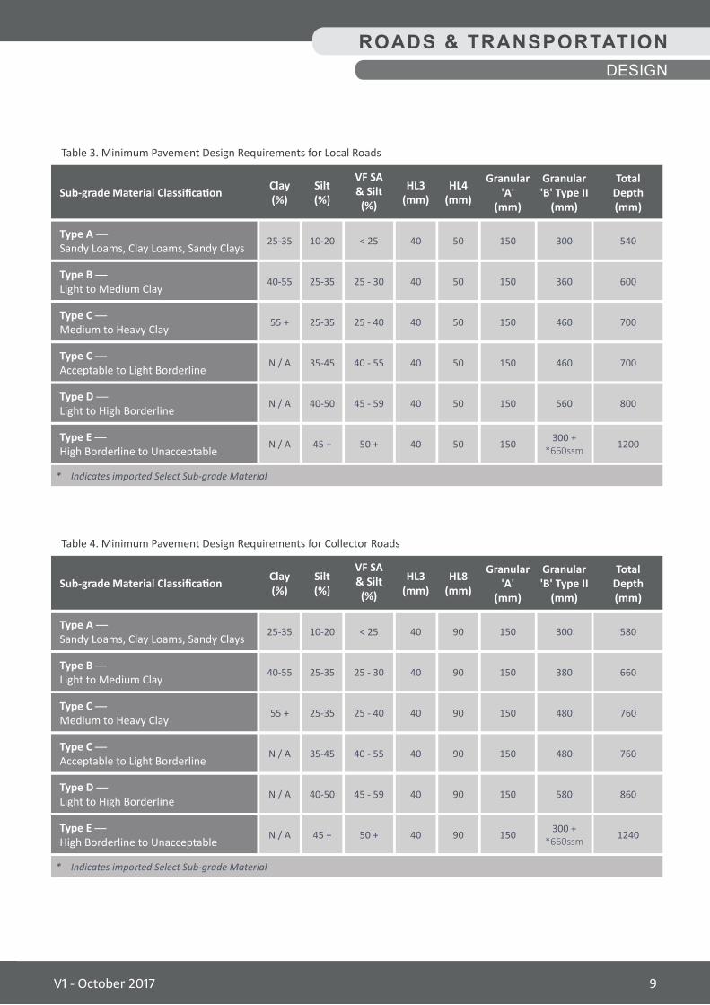
Table 3. Minimum Pavement Design Requirements for Local Roads
HL3(mm)
HL4(mm)
VF SA& Silt (%)
Clay(%)
Silt(%)Sub-grade Material Classification
25-35
55 +
40-55
N / A
N / A
N / A
10-20
25-35
25-35
35-45
40-50
45 +
40
40
40
40
40
40
50
50
50
50
50
50
< 25
25 - 40
25 - 30
40 - 55
45 - 59
50 +
150
150
150
150
150
150
300
460
360
460
560
300 +*660ssm
540
700
600
700
800
1200
Type A — Sandy Loams, Clay Loams, Sandy Clays
Type C — Medium to Heavy Clay
Type B — Light to Medium Clay
Type C — Acceptable to Light Borderline
Type D — Light to High Borderline
Type E — High Borderline to Unacceptable
Granular'A'
(mm)
Granular'B' Type II
(mm)
TotalDepth (mm)
* Indicates imported Select Sub-grade Material
Table 4. Minimum Pavement Design Requirements for Collector Roads
HL3(mm)
HL8(mm)
VF SA& Silt (%)
Clay (%)
Silt (%)Sub-grade Material Classification
25-35
55 +
40-55
N / A
N / A
N / A
10-20
25-35
25-35
35-45
40-50
45 +
40
40
40
40
40
40
90
90
90
90
90
90
< 25
25 - 40
25 - 30
40 - 55
45 - 59
50 +
150
150
150
150
150
150
300
480
380
480
580
300 +*660ssm
580
760
660
760
860
1240
Type A — Sandy Loams, Clay Loams, Sandy Clays
Type C — Medium to Heavy Clay
Type B — Light to Medium Clay
Type C — Acceptable to Light Borderline
Type D — Light to High Borderline
Type E — High Borderline to Unacceptable
Granular'A'
(mm)
Granular'B' Type II
(mm)
TotalDepth (mm)
* Indicates imported Select Sub-grade Material
ROADS & TRANSPORTATIONDESIGN
V1 - October 2017 9
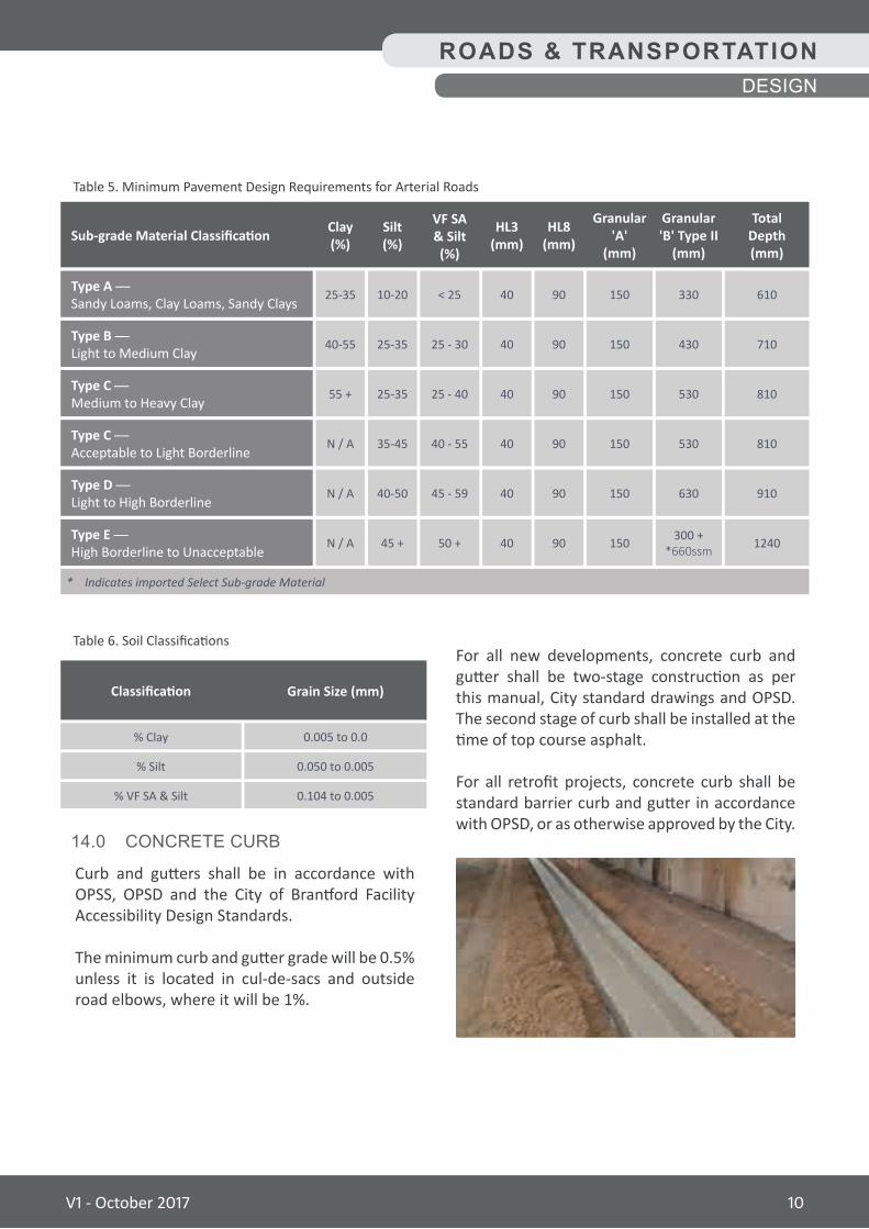
Table 5. Minimum Pavement Design Requirements for Arterial Roads
HL3(mm)
HL8(mm)
VF SA& Silt (%)
Clay (%)
Silt (%)Sub-grade Material Classification
25-35
55 +
40-55
N / A
N / A
N / A
10-20
25-35
25-35
35-45
40-50
45 +
40
40
40
40
40
40
90
90
90
90
90
90
< 25
25 - 40
25 - 30
40 - 55
45 - 59
50 +
150
150
150
150
150
150
330
530
430
530
630
300 +*660ssm
610
810
710
810
910
1240
Type A — Sandy Loams, Clay Loams, Sandy Clays
Type C — Medium to Heavy Clay
Type B — Light to Medium Clay
Type C — Acceptable to Light Borderline
Type D — Light to High Borderline
Type E — High Borderline to Unacceptable
Granular'A'
(mm)
Granular'B' Type II
(mm)
TotalDepth (mm)
* Indicates imported Select Sub-grade Material
ROADS & TRANSPORTATIONDESIGN
Table 6. Soil Classifications
0.005 to 0.0
0.050 to 0.005
0.104 to 0.005
% Clay
% Silt
% VF SA & Silt
Classification Grain Size (mm)
14.0 CONCRETE CURB
Curb and gutters shall be in accordance with OPSS, OPSD and the City of Brantford Facility Accessibility Design Standards.
The minimum curb and gutter grade will be 0.5% unless it is located in cul-de-sacs and outside road elbows, where it will be 1%.
For all new developments, concrete curb and gutter shall be two-stage construction as per this manual, City standard drawings and OPSD. The second stage of curb shall be installed at the time of top course asphalt.
For all retrofit projects, concrete curb shall be standard barrier curb and gutter in accordance with OPSD, or as otherwise approved by the City.
V1 - October 2017 10
15.0 SUBDRAINS
Subdrains shall be in accordance with OPSS and shall be considered on a case-by-case basis as specified by the Geotechnical Engineer. Subdrains shall include the connection of an outlet to a drainage structure or another approved drainage outlet.
Subdrain shall be perforated high density polyethylene pipe complete with geotextile sock with a minimum diameter of 150 mm and a minimum slope of 0.5% shall be installed continuously below the curb and gutter, unless soil conditions warrant otherwise.
16.0 DRIVEWAY AND DRIVEWAYS APPROACHES
16.1 GeneralRequirements
Driveway and approaches / curb depressions shall be designed in accordance with OPSS, OPSD, City of Brantford Site Plan Manual and the City of Brantford Facility Accessibility Design Standards.
Existing driveway to property and driveway approaches shall be replaced with like materials if impacted by construction activities.
New driveway and driveway approaches shall be submitted to the City for review and approval.
Existing curb returns at driveways will be reinstated on a case-by-case basis as approved by the City.
A minimum driveway separation distance shall be determined based on TAC standards and in accordance with OPSS.
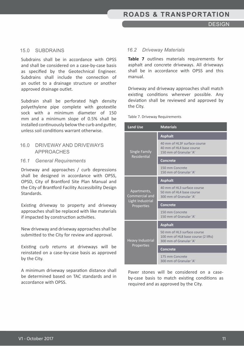
16.2 DrivewayMaterials
Table 7 outlines materials requirements for asphalt and concrete driveways. All driveways shall be in accordance with OPSS and this manual.
Driveway and driveway approaches shall match existing conditions wherever possible. Any deviation shall be reviewed and approved by the City.
Paver stones will be considered on a case-by-case basis to match existing conditions as required and as approved by the City.
Table 7. Driveway Requirements
Land Use
Apartments, Commercial and Light Industrial
Properties
Heavy Industrial Properties
Single Family Residential
40 mm of HL3 surface course50 mm of HL4 base course300 mm of Granular 'A'
50 mm of HL3 surface course100 mm of HL8 base course (2 lifts)300 mm of Granular 'A'
40 mm of HL3F surface course40 mm of HL4 base course150 mm of Granular 'A'
150 mm Concrete150 mm of Granular 'A'
175 mm Concrete300 mm of Granular 'A'
150 mm Concrete150 mm of Granular 'A'
Asphalt
Asphalt
Asphalt
Concrete
Concrete
Concrete
Materials
ROADS & TRANSPORTATIONDESIGN
V1 - October 2017 11
Roundabouts shall be considered for installation at the following locations:
• All locations which meet or will meet future all-way stop or traffic signal warrants should be studied for feasibility of installing roundabouts.
• Existing intersections which may be experiencing capacity problems, those operating at poor levels of service or those which have collision problems are locations which could be improved by conversion to roundabouts.
• Development-related intersections: the best opportunities to implement roundabouts will occur through the development process where major issues, such as land requirements and construction costs, can be most easily dealt with and roundabouts can be integrated into the overall design concept.
• Capital Project Forecast: as part of the yearly roadway improvement capital program, locations which will be subject to major reconstruction should be considered candidates for roundabout conversions and should be reviewed to determine the feasibility of roundabout implementation.
17.2 InitialAssessment
An initial assessment is required to confirm whether a roundabout is feasible.
Although roundabouts are not specifically subject to the Class Environmental Assessment (EA) process, stakeholders will be contacted and the public advised of any roundabouts planned as part of a capital project. Public information centres (PICs) shall be held to allow for public input.
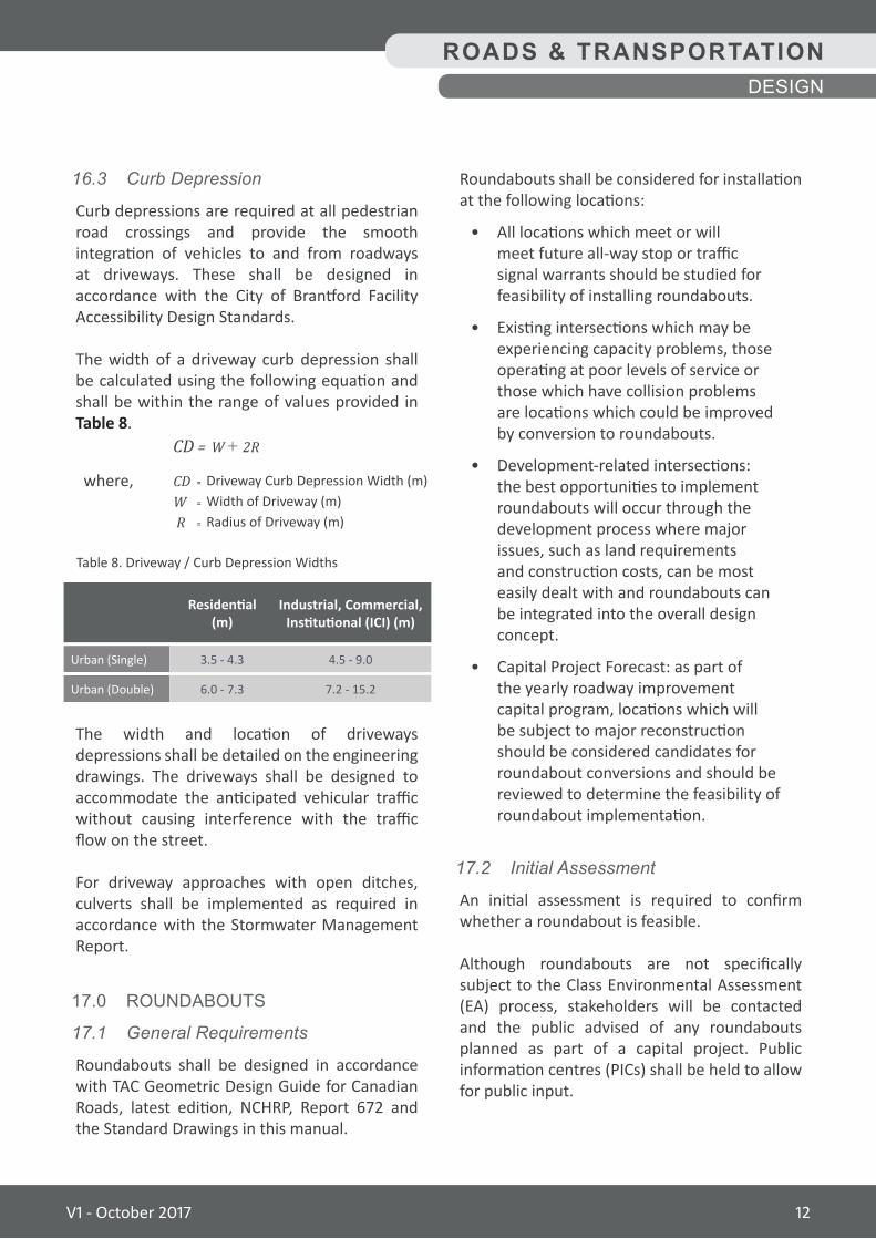
16.3 CurbDepression
Curb depressions are required at all pedestrian road crossings and provide the smooth integration of vehicles to and from roadways at driveways. These shall be designed in accordance with the City of Brantford Facility Accessibility Design Standards.
The width of a driveway curb depression shall be calculated using the following equation and shall be within the range of values provided in Table 8.
CD = W + 2R
where, CD W R
The width and location of driveways depressions shall be detailed on the engineering drawings. The driveways shall be designed to accommodate the anticipated vehicular traffic without causing interference with the traffic flow on the street.
For driveway approaches with open ditches, culverts shall be implemented as required in accordance with the Stormwater Management Report.
17.0 ROUNDABOUTS
17.1 GeneralRequirements
Roundabouts shall be designed in accordance with TAC Geometric Design Guide for Canadian Roads, latest edition, NCHRP, Report 672 and the Standard Drawings in this manual.
ROADS & TRANSPORTATIONDESIGN
= Driveway Curb Depression Width (m)= Width of Driveway (m)= Radius of Driveway (m)
Table 8. Driveway / Curb Depression Widths
Urban (Single)
Urban (Double)
3.5 - 4.3
6.0 - 7.3
4.5 - 9.0
7.2 - 15.2
Residential(m)
Industrial, Commercial, Institutional (ICI) (m)
V1 - October 2017 12
6. Nearby Structures or Traffic Control: Is the location near a structure?
A roundabout may not require additional approach lanes and therefore not require that a nearby overpass or underpass be widened.
Is it near a signalized intersection where queues may spill back into the roundabout? Is it located near a railway crossing, where queues may block the railway tracks?
Traffic signals can be interconnected with a railway crossing, but not a roundabout.
7. Nearby Driveways: Do any driveways need to be relocated because of splitter islands?
8. Land Use Context: Is there a land use transition where a roundabout could notify motorists of a change in the road environment? Can they be used at either end of a commercial corridor to accommodate U-turns, allowing access driveways to be right turns only?
This can mean more commercial sites served with driveways spaced closer together.
9. Traffic Calming: Are high traffic speeds being experienced, or likely, due to the design of the road and the surrounding land uses?
10. Vulnerable Road Users: Does the intersection have high numbers of bicyclists, or are there visually impaired pedestrians?
11. Technical Constraints: Are there any steep grades, unusual drainage, possible difficulties with meeting sight distance requirements, that may preclude a roundabout?
17.2 InitialAssessment(cont'd)
Criteria useful for an initial assessment of roundabouts at existing or new intersections as part of a capital project include:
1. Right-of-Way (ROW): Is there enough space for a roundabout, or is additional ROW or property required?
The size of a roundabout will depend on the design vehicle to be accommodated and traffic flows that dictate whether the roundabout is single-lane or multi-lane.
2. Intersection Geometry: Does the intersection have an offset, high skew angle, or more than four legs?
Roundabouts can accommodate unusual geometry if there is sufficient ROW.
3. Safety: Are there high numbers of angle and turning movement collisions that could be mitigated with a roundabout?
4. Delays or Queues: Are there high delays or long vehicle queues being experienced that could be mitigated with a roundabout?
5. Traffic Flows: Are existing or forecast traffic flows relatively balanced between approaches?
However, unbalanced flows do not necessarily mean a roundabout is not a suitable alternative, as there are other benefits to roundabouts such as safety.
Also consider if there a high percentage of turning movements?
High left turn flows, for instance, favours roundabouts because of signal lost time.
ROADS & TRANSPORTATIONDESIGN
V1 - October 2017 13
17.2 InitialAssessment(cont'd)
An Initial Assessment Report will be prepared by the designer outlining the results and recommendations for the implementation of a roundabout for review and approval by the City.
18.0 PEDESTRIAN WAYS
18.1 GeneralRequirements
Improving accessibility of the built environment not only meets Accessibility for Ontarians with Disabilities Act (AODA) compliance requirements but also supports the City’s commitment to the Walkability Charter. The Walkability Charter aims to create a barrier-free community to promote inclusion and social / economic participation of all residents and visitors.
Design of pedestrian ways shall be in accordance with OPSS, OPSD, AODA, TAC Geometric Design Guide for Canadian Roads and the City of Brantford Facility Accessibility Design Standards.
The Typical Cross-sections in this manual shall be used as a guideline for the location and design of sidewalks and multi-use trails on all road classifications.
18.2 Sidewalks
The location and extent of sidewalks shall be reviewed and approved by the City.
Sidewalk locations should first be located depending on factors such as continuity of routes and direct routes to major pedestrian destinations or attractions such as schools, parks, libraries, community mail boxes, commercial properties.
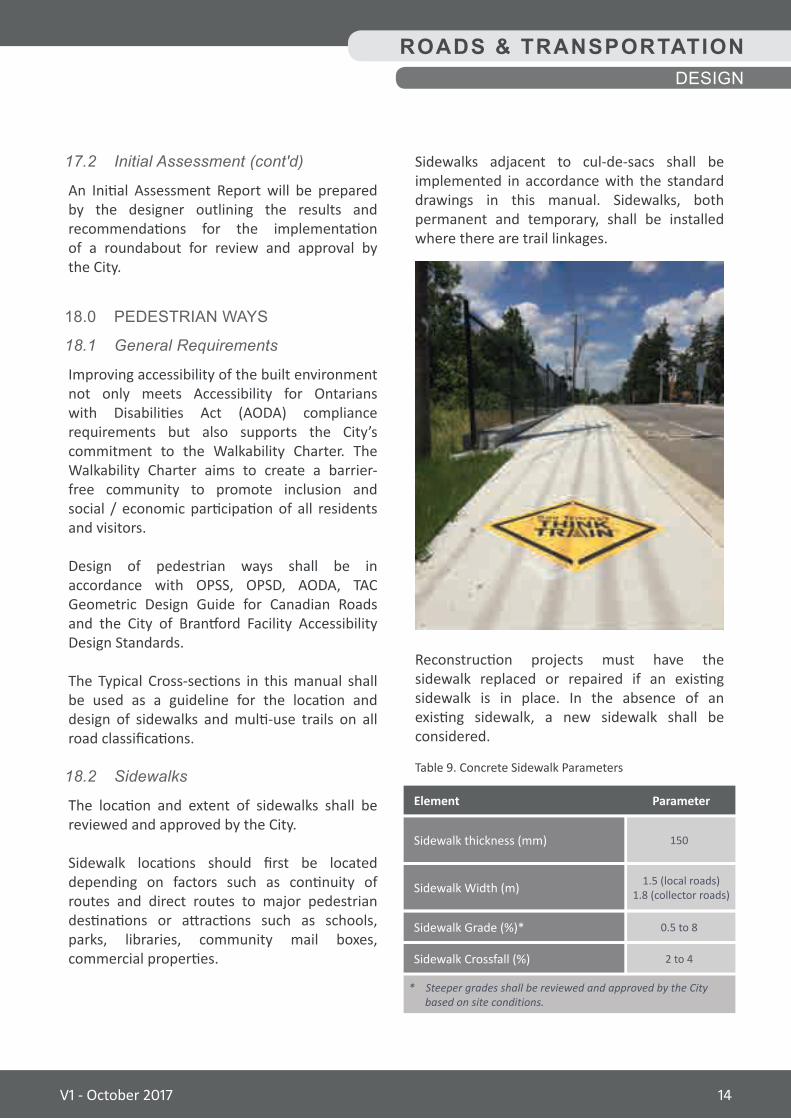
Sidewalks adjacent to cul-de-sacs shall be implemented in accordance with the standard drawings in this manual. Sidewalks, both permanent and temporary, shall be installed where there are trail linkages.
Reconstruction projects must have the sidewalk replaced or repaired if an existing sidewalk is in place. In the absence of an existing sidewalk, a new sidewalk shall be considered.
ROADS & TRANSPORTATIONDESIGN
Table 9. Concrete Sidewalk Parameters
Sidewalk thickness (mm)
Sidewalk Width (m)
Sidewalk Grade (%)*
Sidewalk Crossfall (%)
150
1.5 (local roads)1.8 (collector roads)
0.5 to 8
2 to 4
ParameterElement
* Steeper grades shall be reviewed and approved by the City based on site conditions.
V1 - October 2017 14
19.0 BUS STOPS AND SHELTERS
Bus stops and bus shelters shall provide barrier-free access, meeting the design standards outlined in the City of Brantford's Facility Accessibility Design (FAD) Standards and the standards stated herein.
Bus Shelters shall:
• Be located on firm, concrete, level pads approximately at the same elevation as the sidewalk or walkway.
• Have clearances around at least two sides of the shelter, including the landing pad side, of at least 1.22 m.
• Be set back a minimum of 0.5 m from curbs and sidewalks, to provide sufficient space for snow clearing.
• Provide a clear view of oncoming traffic.
• Incorporate sufficient clear floor space to accommodate a person using a wheelchair or scooter.
• Feature at least one seat with armrests.
• Incorporate decals and other safety features on all glazed panels surrounding bus shelters.
Bus Stops shall:
• Be located as close to intersections as possible and their location coordinated with neighbourhood train connections and building entrances.
• Incorporate a paved, firm level surface.
• Have minimum dimensions of 10.0 m (parallel to the curb) by 2.5 m.
• Where necessary, be connected to adjacent sidewalks.
18.3 Multi-UseTrails
The design of multi-use trails will depend on the number of users, the neighbourhood demography and the surrounding environment that the trail or pathway will pass through. The location and extent of multi-use trails shall be reviewed and approved by the City early in design. Multi-use trails shall be in accordance with Accessibility for Ontarians with Disabilities Act (AODA) guidelines.
Multi-use trails shall contain the following minimum pavement structure: 40 mm (HL3F), 40 mm (HL4) and 150 mm (Granular A). Permeable pavement shall be considered where suitable.
The minimum width for multi-use trails shall be 3.0 m, with a 0.6 m buffer from property line and other obstructions. The exact width will depend on its anticipated use, the infrastructure adjacent to it, its surrounding natural features, topography and the area through which it passes.
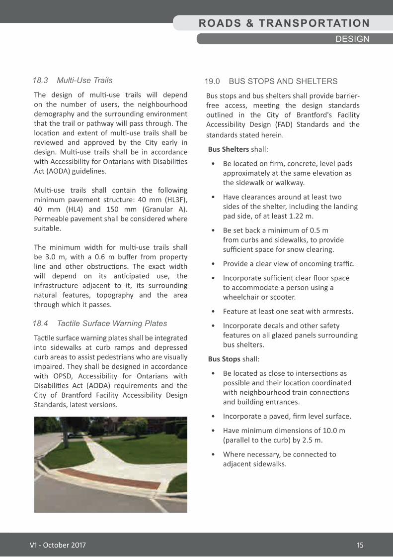
18.4 TactileSurfaceWarningPlates
Tactile surface warning plates shall be integrated into sidewalks at curb ramps and depressed curb areas to assist pedestrians who are visually impaired. They shall be designed in accordance with OPSD, Accessibility for Ontarians with Disabilities Act (AODA) requirements and the City of Brantford Facility Accessibility Design Standards, latest versions.
ROADS & TRANSPORTATIONDESIGN
V1 - October 2017 15
20.0 TRAFFIC CONTROL
20.1 GeneralRequirements
Designs for traffic control devices shall be in accordance with the TAC Geometric Design Guide for Canadian Roads, Ontario Traffic Manual and the Highway Traffic Act.
A Pavement Marking and Traffic Signage Plan shall be submitted for approval by the City which includes but is not limited to all required traffic signals, signs and markings, such as:
• Directional
• Parking and Accessible Parking Signs
• Visibility Triangles
• Vehicle Turning radii
• Abutting Streets
• Traffic Islands (where applicable)
• Pavement Markings
20.2 TrafficControlSignals
Traffic signals shall be considered warranted if intersection conditions meet or exceed the requirements of Ontario Traffic Manual – Book 12 and approved by the City. The general spacing between signalized intersections will be based on the road classification and will be determined by the Traffic Impact Study (TIS).
20.3 IntersectionPedestrianSignals
Traffic signals shall be considered warranted if intersection conditions meet or exceed the requirements of Ontario Traffic Manual – Book 12 and approved by the City. Sidewalks shall provide access to pedestrian activated (pushbutton) signals. Where required, designs shall be in accordance with Accessibility for Ontarians with Disabilities Act (AODA) requirements and the City of Brantford Facility Accessibility Design Standards, latest edition.
20.4 ElectricalDesign
Electrical Design for intersections shall be in accordance with the following as well as Ministry of Transportation Traffic Signal Design manual and OPSS.
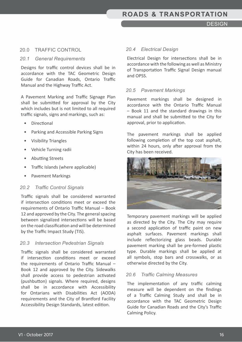
20.5 PavementMarkings
Pavement markings shall be designed in accordance with the Ontario Traffic Manual – Book 11 and the standard drawings in this manual and shall be submitted to the City for approval, prior to application.
The pavement markings shall be applied following completion of the top coat asphalt, within 24 hours, only after approval from the City has been received.
Temporary pavement markings will be applied as directed by the City. The City may require a second application of traffic paint on new asphalt surfaces. Pavement markings shall include reflectorizing glass beads. Durable pavement marking shall be pre-formed plastic type. Durable markings shall be applied at all symbols, stop bars and crosswalks, or as otherwise directed by the City.
20.6 TrafficCalmingMeasures
The implementation of any traffic calming measure will be dependent on the findings of a Traffic Calming Study and shall be in accordance with the TAC Geometric Design Guide for Canadian Roads and the City’s Traffic Calming Policy.
ROADS & TRANSPORTATIONDESIGN
V1 - October 2017 16
21.0 STREET LIGHTING
21.1 GeneralRequirements
Lighting shall be designed in accordance with the Illuminating Engineering Society of North America (IESNA) RP-8, Roadway Lighting. General lighting requirements are as follows:
• Roadway lighting should provide appropriate and sufficient illumination for pedestrian security and safety, traffic safety and enhancement of external building design and landscaped open space.
• Design of lighting and light fixtures shall be compatible with the character of the building(s), landscaping and the site.
• The type, location, height, intensity and direction of lighting shall ensure that glare is not cast onto adjacent residential properties adversely affecting the living environment. No light source shall directly or negatively impinge upon any adjacent residential lots.
• Light poles must not conflict with the location of existing or proposed trees and landscaping on the site or any proposed tree protection measures.
• A Photometric Plan or (‘Site Lighting Plan’) should demonstrate general compliance with the City’s lighting standards.
21.2 PhotometricPlanSubmission Requirements
The Photometric Plan shall be prepared and should reference ‘LUX’ units of measure for information purposes.
The Plan shall include a point-by-point photometric grid superimposed over the site that clearly indicates the proposed site lighting levels.
Other plan requirements include:
• A fixture legend, indicating the fixture details
• Arm length and height
• LED wattage
• Shield specifications (if applicable)
• LED Colour Rendering Index rating(s)
• Fixture light shield locations
• A chart that calculates average, minimum and maximum LUX and foot-candle, veiling luminescence and uniformity.
21.3 PoleTypes
Pole materials shall include:
• Aluminum
• Concrete
21.4 LightTypes
Light types shall include:
• Decoratives
• Cobra head
ROADS & TRANSPORTATIONDESIGN
V1 - October 2017 17
24.0 STREET TREES
24.1 GeneralRequirements
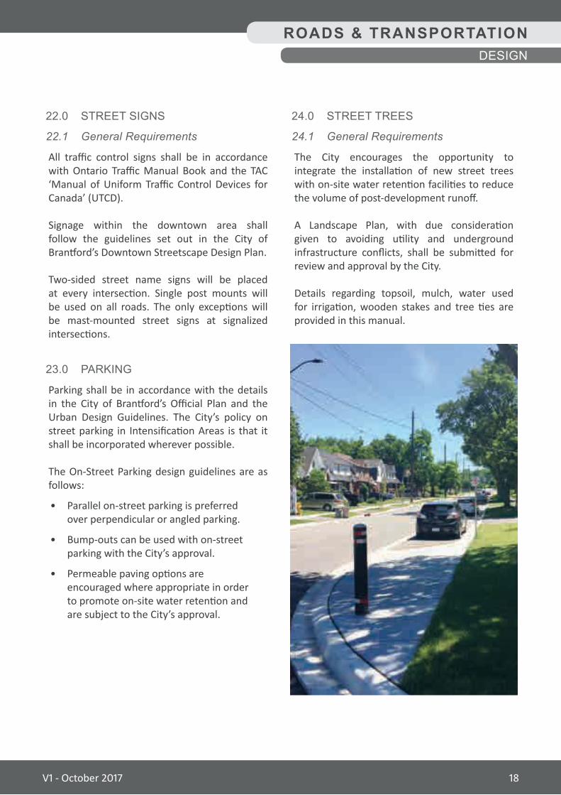
The City encourages the opportunity to integrate the installation of new street trees with on-site water retention facilities to reduce the volume of post-development runoff.
A Landscape Plan, with due consideration given to avoiding utility and underground infrastructure conflicts, shall be submitted for review and approval by the City.
Details regarding topsoil, mulch, water used for irrigation, wooden stakes and tree ties are provided in this manual.
22.0 STREET SIGNS
22.1 GeneralRequirements
All traffic control signs shall be in accordance with Ontario Traffic Manual Book and the TAC ‘Manual of Uniform Traffic Control Devices for Canada’ (UTCD).
Signage within the downtown area shall follow the guidelines set out in the City of Brantford’s Downtown Streetscape Design Plan.
Two-sided street name signs will be placed at every intersection. Single post mounts will be used on all roads. The only exceptions will be mast-mounted street signs at signalized intersections.
23.0 PARKING
Parking shall be in accordance with the details in the City of Brantford’s Official Plan and the Urban Design Guidelines. The City’s policy on street parking in Intensification Areas is that it shall be incorporated wherever possible.
The On-Street Parking design guidelines are as follows:
• Parallel on-street parking is preferred over perpendicular or angled parking.
• Bump-outs can be used with on-street parking with the City’s approval.
• Permeable paving options are encouraged where appropriate in order to promote on-site water retention and are subject to the City’s approval.
ROADS & TRANSPORTATIONDESIGN
V1 - October 2017 18
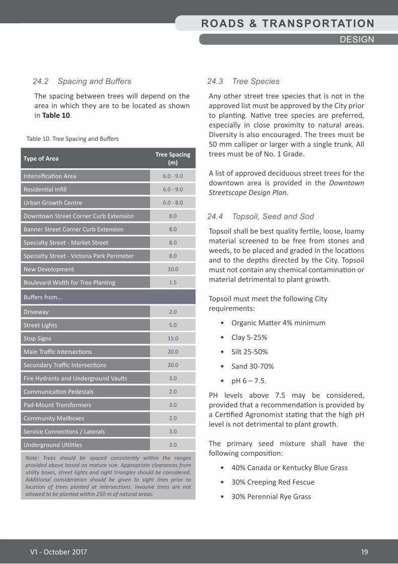
24.2 SpacingandBuffers
The spacing between trees will depend on the area in which they are to be located as shown in Table 10.
Table 10. Tree Spacing and Buffers
Intensification Area
Driveway
Specialty Street - Market Street
Secondary Traffic Intersections
Urban Growth Centre
Stop Signs
New Development
Communication Pedestals
Residential Infill
Street Lights
Specialty Street - Victoria Park Perimeter
Fire Hydrants and Underground Vaults
Downtown Street Corner Curb Extension
Banner Street Corner Curb Extension
Main Traffic Intersections
Boulevard Width for Tree Planting
Pad-Mount Transformers
Service Connections / Laterals
Community Mailboxes
Underground Utilities
6.0 - 9.0
2.0
8.0
20.0
6.0 - 8.0
15.0
10.0
2.0
6.0 - 9.0
5.0
8.0
3.0
8.0
8.0
20.0
1.5
3.0
3.0
2.0
3.0
Tree Spacing (m)Type of Area
Buffers from...
Note: Trees should be spaced consistently within the ranges provided above based on mature size. Appropriate clearances from utility boxes, street lights and sight triangles should be considered. Additional consideration should be given to sight lines prior to location of trees planted at intersections. Invasive trees are not allowed to be planted within 250 m of natural areas.
ROADS & TRANSPORTATIONDESIGN
24.3 TreeSpecies
Any other street tree species that is not in the approved list must be approved by the City prior to planting. Native tree species are preferred, especially in close proximity to natural areas. Diversity is also encouraged. The trees must be 50 mm calliper or larger with a single trunk. All trees must be of No. 1 Grade.
A list of approved deciduous street trees for the downtown area is provided in the Downtown Streetscape Design Plan.
24.4 Topsoil,SeedandSod
Topsoil shall be best quality fertile, loose, loamy material screened to be free from stones and weeds, to be placed and graded in the locations and to the depths directed by the City. Topsoil must not contain any chemical contamination or material detrimental to plant growth.
Topsoil must meet the following Cityrequirements:
• Organic Matter 4% minimum
• Clay 5-25%
• Silt 25-50%
• Sand 30-70%
• pH 6 – 7.5.
PH levels above 7.5 may be considered, provided that a recommendation is provided by a Certified Agronomist stating that the high pH level is not detrimental to plant growth.
The primary seed mixture shall have the following composition:
• 40% Canada or Kentucky Blue Grass
• 30% Creeping Red Fescue
• 30% Perennial Rye Grass
V1 - October 2017 19
25.0 BOULEVARD DESIGN
Street furniture, such as seating, planters, bollards, waste receptacles and recycling centres for the downtown streetscape will be as per the City of Brantford's Downtown Streetscape Design Plan.
Street furniture in other areas of the City shall be in accordance with the Urban Design Guidelines for Intensification Proposals.
Typical cross-sections shall be referenced when placing street furniture to avoid utility conflicts and ensure proper clear zone setbacks from edge of driving lane.
24.4 Topsoil,SeedandSod(cont'd)
Bags shall bear the seed supplier’s label clearly indicating species’ content, grade and mass as well as the recommended seeding rate for the establishment of new lawn areas.
Sod shall be Commercial Grade Kentucky Bluegrass Nursery Sod according to the Specifications, Classifications and Use of Turfgrass Sod for Nursery Sod Growers Association of Ontario.
Sod shall be seeded and established in nursery sod fields as a turf-grass sod. There shall be no more than 5 broad-leaf weeds per 40 m2 of sod and up to 20% non-specified grass.
Sod shall be of sufficient density that no surface soil is visible. The grass height shall be 30 mm minimum and 70 mm maximum.
Starter fertilizer shall comply with the provisions of the Canada Fertilizers Act and Fertilizer Regulations.
Fertilizer shall be supplied in bags bearing the manufacturer’s label indicating mass and analysis.
All fertilizer shall be in granular form: dry, free flowing, free from lumps and with an analysis of 8-32-16.
ROADS & TRANSPORTATIONDESIGN
V1 - October 2017 20
In the case where an encroachment on the adjacent property is inevitable, a written consent from the property owner shall be obtained. Coordination of the easement shall be through the City.
Retaining walls that exceed 1.0 m in exposed height are required to have a detailed drawing for the proposed retaining wall. Rails shall be located at the top of the wall.
The design, drawings and construction compliance certification shall be stamped by a Professional Engineer and submitted to the City for approval.
All private retaining walls shall be located on private property and shall conform to standards outlined in the City of Brantford Site Plan Manual.
26.0 FENCES AND WALLS
26.1 Fences
Fencing shall be implemented within the ROW as required by the City. Fencing abutting City property shall be located 0.3 m from the property line in the ROW.
Fencing is not required where noise barrier walls are to be installed. All private fencing shall be located on private property and shall conform to standards outlined in the City of Brantford's Site Plan Manual and in City Fencing By-law.
26.2 NoiseAttenuationWalls
The acoustical design and structure of all required noise attenuation walls shall be approved by the City. A noise attenuation wall abutting City property shall be located 0.3 m from the property line in the ROW.
All private noise attenuation walls shall be located on private property and shall conform to standards outlined in the City of Brantford's Site Plan Manual.
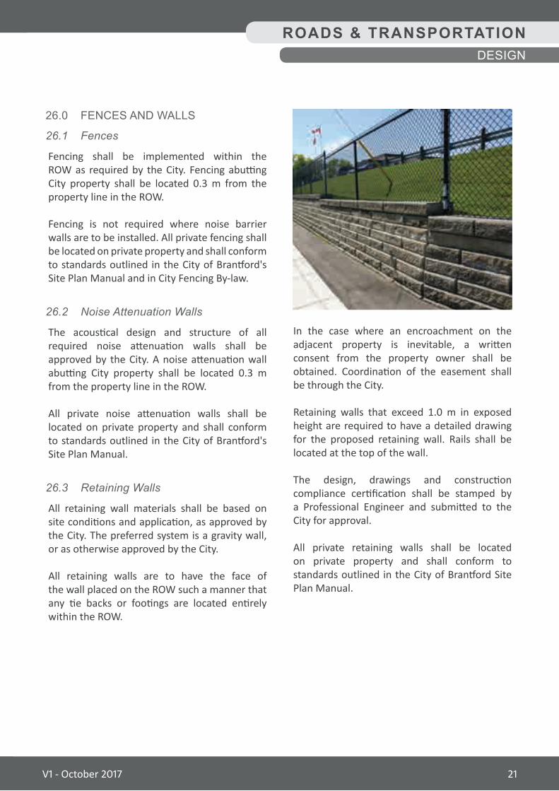
26.3 RetainingWalls
All retaining wall materials shall be based on site conditions and application, as approved by the City. The preferred system is a gravity wall, or as otherwise approved by the City.
All retaining walls are to have the face of the wall placed on the ROW such a manner that any tie backs or footings are located entirely within the ROW.
ROADS & TRANSPORTATIONDESIGN
V1 - October 2017 21
ROADS AND TRANSPORTATION
Construction
V1 - October 2017 22
— Asphalt Cement —
Shall be as per OPSS. The City reserves the right to upgrade the PGAC as per Table A-2 when noted in Special Provisions.
— Winter Heating Charges —
Winter Heat charges shall be deemed to be included in the various unit prices bid in the contract for asphalt work.
— Milling and Disposal —
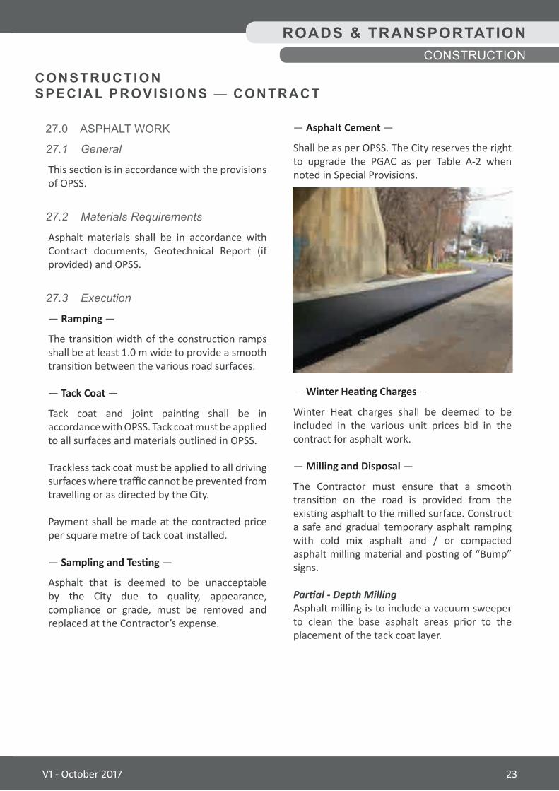
The Contractor must ensure that a smooth transition on the road is provided from the existing asphalt to the milled surface. Construct a safe and gradual temporary asphalt ramping with cold mix asphalt and / or compacted asphalt milling material and posting of “Bump” signs.
Partial - Depth MillingAsphalt milling is to include a vacuum sweeper to clean the base asphalt areas prior to the placement of the tack coat layer.
27.0 ASPHALT WORK
27.1 General
This section is in accordance with the provisions of OPSS.
27.2 MaterialsRequirements
Asphalt materials shall be in accordance with Contract documents, Geotechnical Report (if provided) and OPSS.
27.3 Execution
— Ramping —
The transition width of the construction ramps shall be at least 1.0 m wide to provide a smooth transition between the various road surfaces.
— Tack Coat —
Tack coat and joint painting shall be in accordance with OPSS. Tack coat must be applied to all surfaces and materials outlined in OPSS.
Trackless tack coat must be applied to all driving surfaces where traffic cannot be prevented from travelling or as directed by the City.
Payment shall be made at the contracted price per square metre of tack coat installed.
— Sampling and Testing —
Asphalt that is deemed to be unacceptable by the City due to quality, appearance, compliance or grade, must be removed and replaced at the Contractor’s expense.
CONSTRUCTIONSPECIAL PROVIS IONS — CONTRACT
ROADS & TRANSPORTATIONCONSTRUCTION
V1 - October 2017 23
27.3 Execution(cont'd)
— Milling and Disposal (cont'd) —
Full - Depth MillingThis tender item shall include milling of the existing bituminous pavement and the underlying granular base where specified, to the dimensions outlined in the Contract Document.
The operation shall ensure that 100% of the mixed material by mass passes the 50 mm sieve size and 95% passes the 37.5 mm sieve.
The Contractor shall remove and dispose of unsuitable materials that cannot be removed by the milling machine (e.g. Clay-type or larger stones) to reach the depths required to accommodate the new granular / asphalt design depths.
Disposal of Asphalt / Granular Milled MaterialsManagement of asphalt / granular materials by disposal shall be in accordance with current regulations.
— Longitudinal Joints —
The longitudinal edge of the paving lane must be at least 120°C prior to placement of the adjacent lane and initial compaction of the longitudinal joint. If the temperature of the longitudinal edge falls below 120°C the Contractor will be required to use a joint heater to raise and maintain the asphalt temperature to above 120°C.
— Paving Joint Deficiencies —
When matching a compacted joint, the depth of the uncompact mat shall be set to allow for compaction.
Where the joint construction produces a ridge or lip along the longitudinal joint of adjacent mats or joint along any other rigid surface, the joint shall be corrected by one of the following procedures at the discretion of the City.
Milling of the ridge or lip to produce a flush surface across the joint. This milling procedure is not an approved method for the top lift asphalt layer, or full removal and replacement of the lift of the paving lane(s).
— Paving Equipment —
Placement of Hot Mix Asphalt: RoadsHighway Class Pavers and Rollers shall be used to accomplish the placement and compaction of hot mix asphalt pavement on city roads and operated by experienced operators.
Spreader SpecificationsUniformly heated screed, fully floating, hydraulically operated with gradual vibrating controller and a minimum width of 2.4 m and minimum extendable width of 4.0 m with automatic grade and slope controls.
The screed should be capable of producing a desirable, smooth surface and even texture, free of any mat defects such as tearing, shoving, gouging and segregation.
Spreader shall be certified annually by the manufacturer before the start of the paving season.
• Hopper Capacity: minimum 12 tonne
• Track Length: 3 m or equivalent with Rubber tires
• Operating Weight: minimum 15 tonne
ROADS & TRANSPORTATIONCONSTRUCTION
V1 - October 2017 24
— Increase / Decrease in Hot Mix Asphalt Prices —
The City will adjust the payment to the Contractor based on changes to the Ministry of Transportation specifications and performance graded asphalt cement price index.
The price index will be published monthly in the MTO Contract Bulletin and displayed on the OHMPA (www.ohmpa.org) and MTO website (www.mto.gov.on.ca).
The price index will be used to calculate the amount of the payment adjustment per tonne of asphalt cement accepted into the Work.
The price index will be based on the price, excluding taxes, freight on board (FOB) the depots in the Toronto area, of asphalt cement grade PG 58-28 or equivalent. One index will be used to establish and calculate the payment adjustment for all grades.
A payment adjustment per tonne of asphalt cement will be established for each month in which paving occurs when the price index for the month differs by more than $15.00 / tonne from the AC price index for the month prior to the tender opening. When the price index differential is less than $15.00 / tonne, there will be no payment adjustment for that month.
Payment adjustments due to changes in the price index are independent of any other payment adjustments made to hot mix tender items.
Harmonized sales tax (HST) adjustment should be applied to the adjustment. The payment adjustment per tonne will apply to the quantity of asphalt cement in the hot mix accepted into the Work during the month for which it is established.
27.3 Execution(cont'd)
— Placement of Hot Mix Asphalt for Parking Lots and Multi-Use Trails —
Placement of hot mix asphalt pavement for parking lots shall be accomplished by using an approved paver and roller.
Spreader SpecificationsA uniformly heated screed, fully floating, hydraulically operated with gradual vibrating controllers and a minimum width of 2.4 m extended to 4.0 m with an automatic grade and slope controller.
The screed should be capable of producing a desirable, smooth surface and even texture, free from of any mat defects such as tearing, shoving, gouging and segregation.
Spreader shall be certified annually by the manufacturer before the start of the paving season.
• Hopper Capacity: minimum 8 tonne
• Track Length: 2.0 m or equivalent with Rubber tires
27.4 MeasurementforPayment
Measurement for payment shall be per tonne of asphalt cement, by grade.
27.5 BasisforPayment
The unit bid price shall include all labour, equipment and materials to complete the work as noted above. AC indexes will be applied accordingly.
ROADS & TRANSPORTATIONCONSTRUCTION
V1 - October 2017 25
27.5 BasisforPayment(cont'd)
— Increase / Decrease in Hot Mix Asphalt Prices (cont'd)—
The payment adjustment for the month will be calculated by the following means:
1. When AC Prices are Rising by more than $15.00 / tonne:
The payment adjustment to be paid to the Contractor is the result of subtracting the price index for the month prior to the tender opening from the price index in effect when paving takes place, minus the $15.00 float, multiplied by the number of tonnes of PGAC incorporated in the mix(s) as determined by the job mix formula.
HST on the adjustment will be added.
2. When AC Prices are Falling by more than $15.00 / tonne:
The payment adjustment made in favour of the Owner is the result of subtracting the price index in effect when paving takes place, plus the $15.00 float from the price index for the month prior to the tender opening, multiplied by the number of tonnes of PGAC incorporated in the mix(s) as determined by the job mix formula.
HST on the adjustment will be added.
The quantity of new asphalt cement includes all grades of asphalt cement supplied by the Contractor with and without polymer modifiers.
For each month in which a payment adjustment has been established, the quantity of the escalation / de-escalation will be calculated using the hot mix quantity accepted into the Work and its corresponding asphalt cement content as required by the job mix formula.
28.0 PAVEMENT MARKINGS
28.1 General
This section is in accordance with the provisions of OTM, Book 11.
28.2 MaterialsRequirements
Pavement Markings include reflectorizing glass beads. Durable Pavement Marking shall not be pre-formed plastic type.
28.3 Execution
Pavement markings shall be in accordance with the Contract Drawings, this manual and OTM Book 11. The City prior to the application of the pavement markings must approve the pre-marking.
28.4 MeasurementofPayment
Measurement for payment shall be per metre for the length noted in the tender. Symbols shall be by each.
28.5 BasisforPayment
The unit bid price shall include all labour, equipment and materials to inventory prior to construction, layout, pre-mark and install markings in accordance with the Ontario Traffic Manuals.
ROADS & TRANSPORTATIONCONSTRUCTION
V1 - October 2017 26
29.0 GRANULAR MATERIAL
29.1 General
This section is in accordance with the provisions of OPSS.
29.2 MaterialsRequirements
Granular materials supplied and placed under the contract shall meet the requirements of the Contract drawings and OPSS except for the following changes for Granular ‘B’ Type II:
• Granular ‘B’ Type II materials supplied and placed under the contract shall be from natural aggregate and shall meet the OPSS gradation requirements for Type II.
• Pit run material is an approved product for Granular B Type II but must have a minimum of 45% crushed aggregate. If suitable, recycled material for granular ‘A’ shall be considered on a case-by-case basis.
29.3 Execution
The Contractor is responsible for the supply, placement and compaction of Granular materials that will meet the gradation and physical properties in the specifications. Placement of the granular is to be as per the Construction and Detail Drawings and in accordance with OPSS.
Granular material that does not meet specifications must be removed and replaced with acceptable material at the Contractor’s expense.
Before paving will be permitted, the finished granular elevations must meet the design elevations.
29.4 MeasurementofPayment
Measurement for payment shall be per tonne of materials supplied and placed.
ROADS & TRANSPORTATIONCONSTRUCTION
29.5 BasisforPayment
The unit bid price shall include all labour, equipment and materials to supply and place granular material in roadways, driveways, sidewalk and associated appurtenance and culverts.
30.0 CONCRETE CURB
30.1 General
This section is in accordance with the provisions of OPSS.
30.2 MaterialsRequirements
See Section 30.1.
30.3 Execution
A minimum subbase thickness of 150 mm granular ‘A’ is to be used as a base for curbs. The material must be compacted to 98% Standard Proctor Maximum Dry Density (SPMDD) and must extend 300 mm beyond the back of the curb.
Concrete shall have a 28 day compressive strength of 30 MPa.
30.4 MeasurementofPayment
Measurement for payment shall be per metre along the flow line of the gutter whether straight or curved, without separation into types. Such measurements shall include the space occupied by setbacks, gutter outlets and frames with grates.
30.5 BasisforPayment
The unit bid price shall include all labour, equipment and materials to supply and install all types of concrete curbs and gutters, including drop sections at driveways and sidewalk ramps and curb and gutter terminations.
V1 - October 2017 27

When subdrain and outlet pipe are placed below subgrade and the embedment and backfill material are the same material used in the road base or subbase, the embedment and backfill material shall be paid for with the road base or subbase item.
When embedment or backfill material or both are different than the material used for the road base or subbase, payment for the embedment and backfill material shall be included in the Contract price for the pipe subdrain.
32.0 ASPHALT DRIVEWAYS
32.1 General
This section is in accordance with the provisions of OPSS.
32.2 MaterialsRequirements
Materials shall be in accordance with OPSS and as specified in the Contract Documents and Drawings.
32.3 Execution
31.0 SUBDRAIN
31.1 General
This section is in accordance with the provisions of OPSS.
31.2 MaterialsRequirements
The subdrain shall be perforated high density polyethylene pipe with geotextile sock, or as otherwise specified by the Contract.
31.3 Execution
Installation of subdrain pipe shall be in accordance with OPSS and Contract Drawings and Details.
The perforated subdrain will be coupled with a geotextile sock prior to its installation. The subdrain shall be installed after the subgrade cross-section is established.
31.4 MeasurementofPayment
Measurement for payment shall be per metre horizontally along the centreline of the pipe between the ends of the pipe subdrain, including outlets, or between the upstream end of the pipe subdrain and the centre of a maintenance hole, catchbasin, or ditch inlet.
31.5 BasisforPayment
The unit bid price shall include all labour, equipment and materials to do the work.
When excavation and backfilling of subdrain and outlet pipe overlaps the excavation and backfilling required for other work, payment for overlapping excavation and backfilling shall be made in accordance with the specifications.
Table 11. Asphalt Driveway Requirements
Land Use
Apartments, Commercial and Light Industrial
Properties
Heavy Industrial Properties
Single Family Residential
40 mm of HL3 surface course50 mm of HL4 base course300 mm of Granular 'A'
50 mm of HL3 surface course100 mm of HL8 base course (2 lifts)300 mm of Granular 'A'
40 mm of HL3F surface course40 mm of HL4 base course150 mm of Granular 'A'
Asphalt
Asphalt
Asphalt
Materials
ROADS & TRANSPORTATIONCONSTRUCTION
V1 - October 2017 28
ROADS & TRANSPORTATIONCONSTRUCTION
32.4 MeasurementofPayment
Measurement for payment shall be per square metre of existing asphalt (full depth) and granular removal and disposal.
Measurement for payment shall be per tonne of hot mix asphalt and granular ‘A’ supplied and placed at specified depths.
32.5 BasisforPayment
The unit bid price shall include all labour, equipment and materials required to complete the hot mix asphalt and granular work at depths specified above, including excavation, disposal, preparation, supply and placement.
33.0 CONCRETE DRIVEWAYS
33.1 General
This section is in accordance with the provisions of OPSS.
33.2 MaterialsRequirements
See Section 33.1.
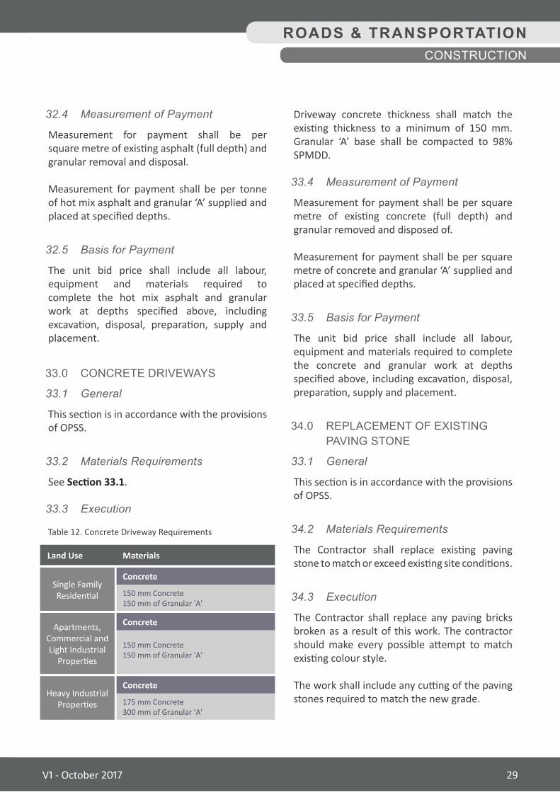
33.3 Execution
Driveway concrete thickness shall match the existing thickness to a minimum of 150 mm. Granular ‘A’ base shall be compacted to 98% SPMDD.
33.4 MeasurementofPayment
Measurement for payment shall be per square metre of existing concrete (full depth) and granular removed and disposed of.
Measurement for payment shall be per square metre of concrete and granular ‘A’ supplied and placed at specified depths.
33.5 BasisforPayment
The unit bid price shall include all labour, equipment and materials required to complete the concrete and granular work at depths specified above, including excavation, disposal, preparation, supply and placement.
34.0 REPLACEMENT OF EXISTING PAVING STONE
33.1 General
This section is in accordance with the provisions of OPSS.
34.2 MaterialsRequirements
The Contractor shall replace existing paving stone to match or exceed existing site conditions.
34.3 Execution
The Contractor shall replace any paving bricks broken as a result of this work. The contractor should make every possible attempt to match existing colour style.
The work shall include any cutting of the paving stones required to match the new grade.
Table 12. Concrete Driveway Requirements
Land Use
Apartments, Commercial and Light Industrial
Properties
Heavy Industrial Properties
Single Family Residential
150 mm Concrete150 mm of Granular 'A'
175 mm Concrete300 mm of Granular 'A'
150 mm Concrete150 mm of Granular 'A'
Concrete
Concrete
Concrete
Materials
V1 - October 2017 29
The concrete shall be poured in place with a broom finish for traction. This same finish applies if it is separated from the curb and gutter by a boulevard.
Where a sidewalk is within 1.0 m of any tree, the concrete shall be reinforced with rebar to provide protection against heaving. Multi-use trail materials shall be in accordance with OPSS and as specified in the Contract Drawings.
35.3 Execution
Construction of concrete sidewalks shall be in accordance with OPSS, OPSD and the Contract Drawings and details:
• Contraction joints shall be sawcut, 5 mm wide and should be cut at a minimum depth of one quarter of the sidewalk thickness.
• Expansion joints shall be placed every 30.0 m centre to centre maximum. Expansion joints shall be constructed to the full depth and width of the slab.
• Contraction joints shall be spaced at 2.5 m centre to centre maximum.
• All joints are to be perpendicular to the line of the sidewalk.
Sidewalks shall be 1.5 m to 1.8 m as specified by the Contract Drawings. They must have firm, stable and slip resistant surfaces. The surface of the paved trail shall be constructed in such a manner as to give a smooth transition between all new construction. The width for multi-use trails or pathways shall be 3.0 m, or as otherwise specified.
The Contractor shall not remove any sidewalk, walkway or trail unless required until such time as the Contractor is prepared to construct new surfaces. If the Contractor removes surfaces for any reason, the Contractor shall maintain and level surface for safe pedestrian access.
34.4 MeasurementofPayment
Measurement for payment shall be per square metre installed.
34.5 BasisforPayment
The unit bid price shall include all labour, equipment and materials to complete the work including: disassemble and stockpile the existing paving stones, replacing damaged paving stones or new as specified, handwork required to reinstate grade and screenings.
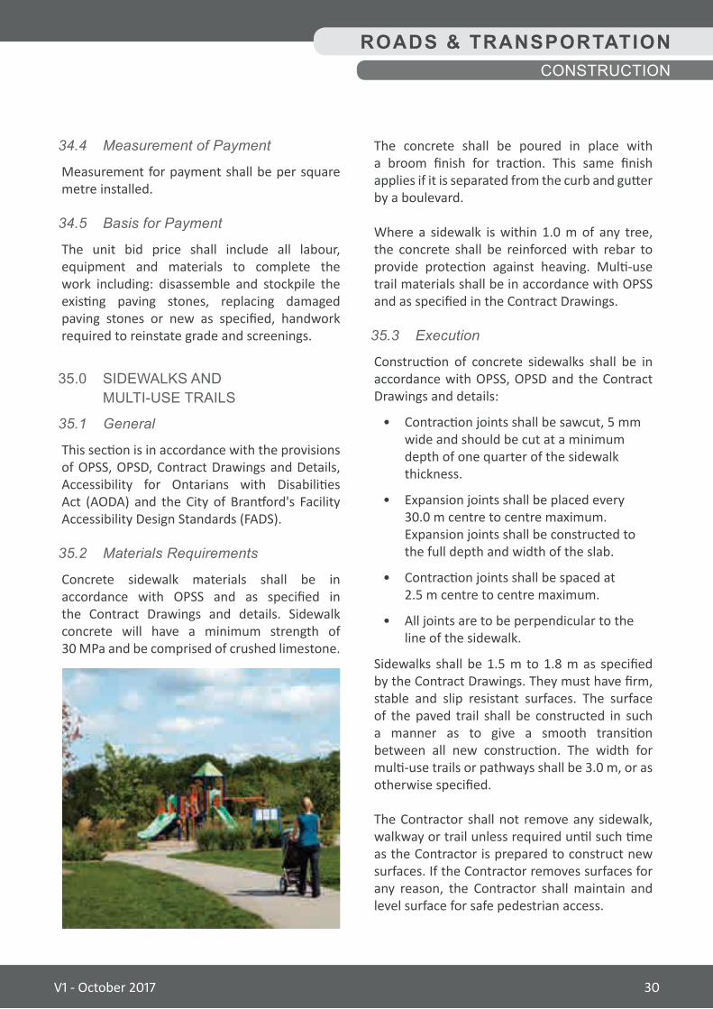
35.0 SIDEWALKS AND MULTI-USE TRAILS
35.1 General
This section is in accordance with the provisions of OPSS, OPSD, Contract Drawings and Details, Accessibility for Ontarians with Disabilities Act (AODA) and the City of Brantford's Facility Accessibility Design Standards (FADS).
35.2 MaterialsRequirements
Concrete sidewalk materials shall be in accordance with OPSS and as specified in the Contract Drawings and details. Sidewalk concrete will have a minimum strength of 30 MPa and be comprised of crushed limestone.
ROADS & TRANSPORTATIONCONSTRUCTION
V1 - October 2017 30
35.4 MeasurementofPayment
Measurement for payment shall be per square metres in area.
35.5 BasisforPayment
The unit bid price shall include all labour, equipment and materials to excavate and fill as outlined above. Payment for Granular ‘A’ shall be included under the appropriate granular item in the Schedule of Tender Unit Prices.
36.0 TACTILE WARNING SURFACES
36.1 General
This section is in accordance with the provisions of OPSD, Accessibility for Ontarians with Disabilities Act (AODA) and the City of Brantford Facility Accessibility Design Standards.
36.2 MaterialsRequirements
Tactile surface warning plates shall be cast iron and be of uniform quality, free from surface defects and shall be provided with an untreated, natural surface finish.
36.3 Execution
Tactile Surface Warning Plates are to be installed at all intersection ramps. The detectable warning system shall be installed in fresh concrete flush with the adjacent sidewalk resulting in a snug fit between tiles to limit water infiltration around the perimeter of the system and between tiles.Installation procedures shall be according to the manufacturer’s specifications.
36.4 MeasurementofPayment
Measurement for payment shall be per plate of 610 mm width acceptably installed to the specified conditions.
36.5 BasisforPayment
The unit bid price shall include all labour, equipment and materials for the installation of cast iron tiles and all other items of work necessary to complete this item in accordance with the contract requirements and other applicable standards.
37.0 TRAFFIC SIGNALS
37.1 General
The following are the requirements for traffic signal installation and shall be in accordance with current regulations.
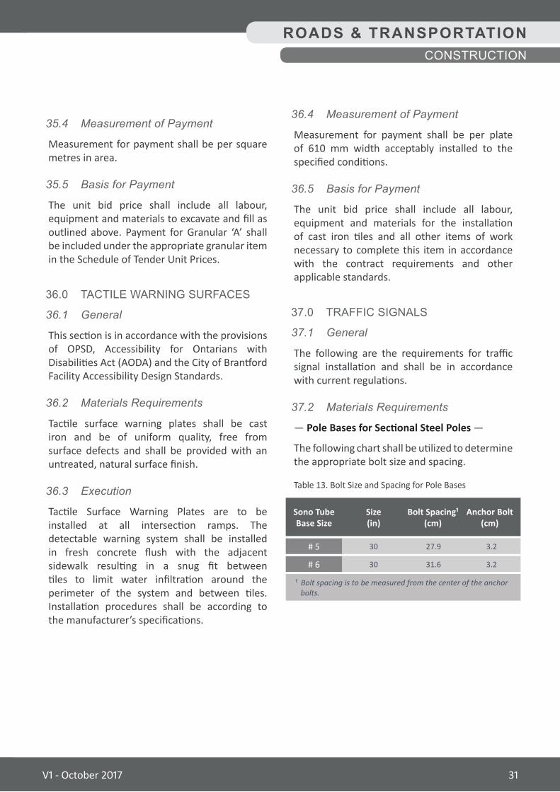
37.2 MaterialsRequirements
— Pole Bases for Sectional Steel Poles —
The following chart shall be utilized to determine the appropriate bolt size and spacing.
ROADS & TRANSPORTATIONCONSTRUCTION
27.930
31.630
3.2
3.2
# 5
# 6
Sono Tube Base Size
Anchor Bolt(cm)
Bolt Spacing¹ (cm)
Size (in)
¹ Bolt spacing is to be measured from the center of the anchor bolts.
Table 13. Bolt Size and Spacing for Pole Bases
V1 - October 2017 31
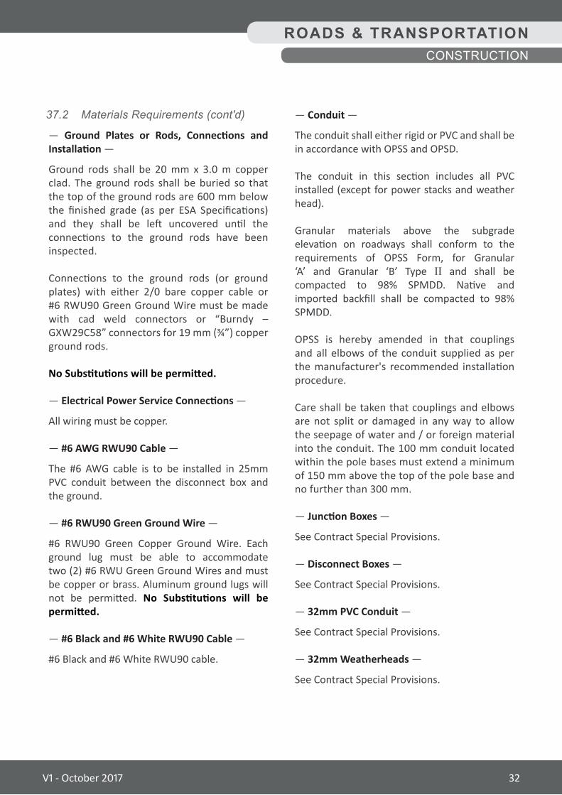
— Conduit —
The conduit shall either rigid or PVC and shall be in accordance with OPSS and OPSD.
The conduit in this section includes all PVC installed (except for power stacks and weather head).
Granular materials above the subgrade elevation on roadways shall conform to the requirements of OPSS Form, for Granular ‘A’ and Granular ‘B’ Type II and shall be compacted to 98% SPMDD. Native and imported backfill shall be compacted to 98% SPMDD.
OPSS is hereby amended in that couplings and all elbows of the conduit supplied as per the manufacturer's recommended installation procedure.
Care shall be taken that couplings and elbows are not split or damaged in any way to allow the seepage of water and / or foreign material into the conduit. The 100 mm conduit located within the pole bases must extend a minimum of 150 mm above the top of the pole base and no further than 300 mm.
— Junction Boxes —
See Contract Special Provisions.
— Disconnect Boxes —
See Contract Special Provisions.
— 32mm PVC Conduit —
See Contract Special Provisions.
— 32mm Weatherheads —
See Contract Special Provisions.
37.2 MaterialsRequirements(cont'd)
— Ground Plates or Rods, Connections and Installation —
Ground rods shall be 20 mm x 3.0 m copper clad. The ground rods shall be buried so that the top of the ground rods are 600 mm below the finished grade (as per ESA Specifications) and they shall be left uncovered until the connections to the ground rods have been inspected.
Connections to the ground rods (or ground plates) with either 2/0 bare copper cable or #6 RWU90 Green Ground Wire must be made with cad weld connectors or “Burndy – GXW29C58” connectors for 19 mm (¾”) copper ground rods.
No Substitutions will be permitted.
— Electrical Power Service Connections —
All wiring must be copper.
— #6 AWG RWU90 Cable —
The #6 AWG cable is to be installed in 25mm PVC conduit between the disconnect box and the ground.
— #6 RWU90 Green Ground Wire —
#6 RWU90 Green Copper Ground Wire. Each ground lug must be able to accommodate two (2) #6 RWU Green Ground Wires and must be copper or brass. Aluminum ground lugs will not be permitted. No Substitutions will be permitted.
— #6 Black and #6 White RWU90 Cable —
#6 Black and #6 White RWU90 cable.
ROADS & TRANSPORTATIONCONSTRUCTION
V1 - October 2017 32
37.2 MaterialsRequirements(cont'd)
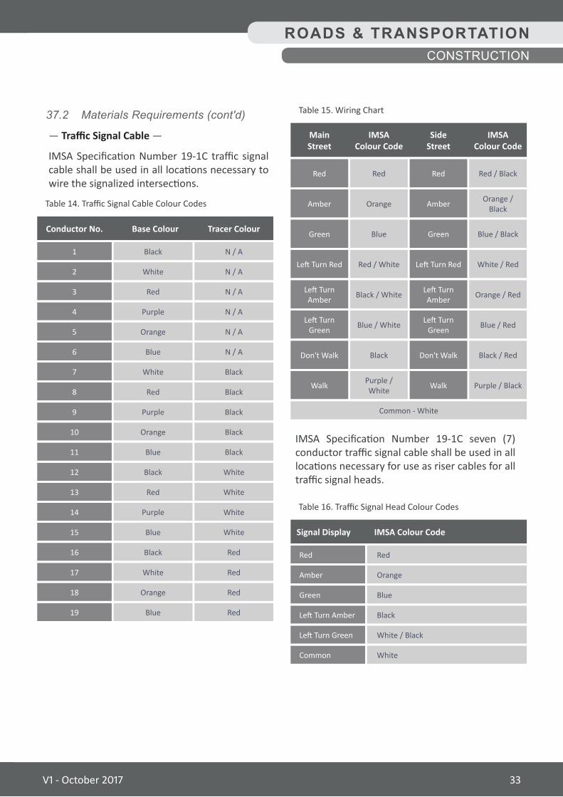
— Traffic Signal Cable —
IMSA Specification Number 19-1C traffic signal cable shall be used in all locations necessary to wire the signalized intersections.
Conductor No. Base Colour Tracer Colour
1
9
5
13
3
11
7
15
18
2
10
6
14
17
4
12
8
16
19
Black
Purple
Purple
Red
Orange
Red
Blue
White
Blue
Orange
White
Orange
Blue
White
Purple
Red
Black
Black
Blue
N / A
Black
N / A
N / A
Black
Black
Red
N / A
Black
N / A
Red
N / A
White
White
White
White
Black
Red
Red
Table 14. Traffic Signal Cable Colour Codes
ROADS & TRANSPORTATIONCONSTRUCTION
IMSA Specification Number 19-1C seven (7) conductor traffic signal cable shall be used in all locations necessary for use as riser cables for all traffic signal heads.
MainStreet
IMSAColour Code
SideStreet
IMSAColour Code
Red
Left Turn Amber
Green
Don't Walk
Amber
Left Turn Green
Left Turn Red
Walk
Red
Left Turn Amber
Green
Don't Walk
Amber
Left Turn Green
Left Turn Red
Walk
Red
Black / White
Blue
Black
Orange
Blue / White
Red / White
Purple / White
Common - White
Red / Black
Orange / Red
Blue / Black
Black / Red
Orange / Black
Blue / Red
White / Red
Purple / Black
Table 15. Wiring Chart
Signal Display IMSA Colour Code
Red
Left Turn Green
Green
Amber
Common
Left Turn Amber
Red
White / Black
Blue
Orange
White
Black
Table 16. Traffic Signal Head Colour Codes
V1 - October 2017 33
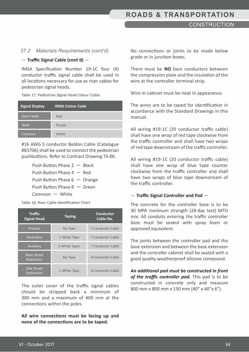
No connections or joints to be made below grade or in junction boxes.
There must be NO bare conductors between the compression plate and the insulation of the wire at the controller terminal strip.
Wire in cabinet must be neat in appearance.
The wires are to be taped for identification in accordance with the Standard Drawings in this manual.
All wiring #19-1C (20 conductor traffic cable) shall have one wrap of red tape clockwise from the traffic controller and shall have two wraps of red tape downstream of the traffic controller.
All wiring #19-1C (20 conductor traffic cable) shall have one wrap of blue tape counter clockwise from the traffic controller and shall have two wraps of blue tape downstream of the traffic controller.
— Traffic Signal Controller and Pad —
The concrete for the controller base is to be 30 MPA minimum strength (28-day test) MTO mix. All conduits entering the traffic controller base must be sealed with spray foam or approved equivalent.
The joints between the controller pad and the base extension and between the base extension and the controller cabinet shall be sealed with a good quality weatherproof silicone compound.
An additional pad must be constructed in front of the traffic controller pad. This pad is to be constructed in concrete only and measure 800 mm x 800 mm x 150 mm (40” x 40”x 6”).
37.2 MaterialsRequirements(cont'd)
— Traffic Signal Cable (cont'd) —
IMSA Specification Number 19-1C four (4) conductor traffic signal cable shall be used in all locations necessary for use as riser cables for pedestrian signal heads.
#16 AWG 5 conductor Beldon Cable (Catalogue #83706) shall be used to connect the pedestrian pushbuttons. Refer to Contract Drawing TS-06.
Push Button Phase 2 — BlackPush Button Phase 4 — RedPush Button Phase 6 — OrangePush Button Phase 8 — GreenCommon — White
The outer cover of the traffic signal cables should be stripped back a minimum of 300 mm and a maximum of 400 mm at the connections within the poles.
All wire connections must be facing up and none of the connections are to be taped.
ROADS & TRANSPORTATIONCONSTRUCTION
Signal Display IMSA Colour Code
Don't Walk
Common
Walk
Red
White
Purple
Table 17. Pedestrian Signal Head Colour Codes
TrafficSignal Head Taping Conductor
Cable No.
Primary
Auxiliary
Secondary
Main Street Pedestrian
Side Street Pedestrian
No Tape
2 White Tapes
1 White Tape
No Tape
1 White Tape
7 Conductor Cable
7 Conductor Cable
7 Conductor Cable
4 Conductor Cable
4 Conductor Cable
Table 18. Riser Cable Identification Chart
V1 - October 2017 34
— Ground Plates or Rods, Connections and Installation —
Ground rods used to ground traffic signal poles must be installed in the junction box adjacent to the pole and be connected to the pole using a “Ground Lug Terminal” with a #6 green ground wire.
Ground plates may be used in place of ground rods.
Trenches for ground wire and ground rods are to be a minimum depth of 600 mm and a minimum width of 150 mm.
— Electrical Power Service Connections —
Installation of the power service shall be completed within the first ten (10) working days of the project to allow the Hydro Authority sufficient time to provide power prior to date of signal turn on.
— #6 AWG RWU90 Cable —
The City will approve location for the disconnect box.
— #6 RWU90 Green Ground Wire —
The ground wire must be connected to each pole by ground lugs in a continuous run and connected to the disconnect box.
If the ground lugs are not preinstalled in the poles, then it is the responsibility of the Contractor to supply and install the ground lugs.
Each ground lug must be able to accommodate two (2) #6 RWU Green Ground Wires and must be copper or brass. Aluminum ground lugs will not be permitted.
There must be a separate #6 RWU90 Green Copper Ground Wire installed from the controller cabinet to the disconnect box.
37.2 MaterialsRequirements(cont'd)
— Traffic Signal Heads —
See Contract Special Provisions.
— Pedestrian Signal Heads —
Install one (1) section Poly Yellow LED pedestrian signal heads complete with rain cap and square aluminum visor or two (2) section Poly Yellow LED pedestrian signal heads complete with countdown timer.
— Audible Pedestrian Pushbuttons —
See Contract Special Provisions.
— Rubber Cushion Hangers —
See Contract Special Provisions.
— Astro or Versa Brackets —
All 4 section or larger traffic signal heads and 300 mm x 300 mm x 300 mm (12” x 12” x 12”) signal head mounted on a mast arm.
— Traffic Signal Poles —
See Contract Special Provisions.
— Temporary Traffic Signal —
See Contract Special Provisions.
37.3 Execution
— Pole Bases —
Concrete pole bases are to be constructed as per OPSS and OPSD in the locations identified in the contract drawings.
The pole base shall be augured, hand dug or utilizing the services of a vac truck as may be required by the location of underground utilities. The pole bases must be constructed of reinforced concrete 30 MPA minimum strength (28-day test) MTO mix.
ROADS & TRANSPORTATIONCONSTRUCTION
V1 - October 2017 35
37.3 Execution(cont'd)
— #6 Black and #6 White RWU90 Cable —
#6 Black and #6 White RWU90 cable shall be installed from the disconnect box to the controller cabinet and connected to the appropriate terminals.
Two (2) #6 Black and one (1) #6 White RWU90 cable shall also be installed from the disconnect box to the power lines.
The Contractor will make the necessary connections to the disconnect box and Brantford Power will make the connections to the power lines. The Contractor is responsible for making all arrangements with Brantford Power and ESA.
— Conduit —
The work under this item shall include all trench excavation, supply and installation in the trench of the duct (either rigid or PVC), backfilling with native material and the compacting of the backfill in the trench, as well as the restoration of the surface of the trench (topsoil and sod, asphalt, concrete sidewalk)
Where the proposed conduit conflicts with underground utilities, the Contractor will adjust the depth of the conduit to accommodate utilities.
The excavation and conduit must be kept free of water at all times.
Where open cut could cause a significant impact on traffic or the public, directional drilling of the conduit is permitted. Directional drilling must be approved by the City prior to the work commencing.
Conduit ends in junction boxes must be located no closer than 200 mm below the junction box lid.
Empty conduits must have the ends sealed (taped or plugged) and a rope pulled through the conduit and tied securely at both ends.
Where PVC conduit extends above ground level, expansion joints must be used.
The Contractor will be required to submit the exact location for conduit to the City for review and approval. Trench and sidewalk cuts must be maintained until all work has been completed.
— Junction Boxes —
A minimum of 50 mm of clearstone rock shall be placed at the bottom of each junction box.
— Disconnect Boxes —
The Contractor shall leave sufficient wire (#6 RWU90 Black & White) coiled at the weather head for the connection to the secondary buss by Brantford Power.
It will be the responsibility of the Contractor to contact Brantford Power three (3) weeks before the power to the service is required and request a “Service Layout”. The Contractor will meet the service representative on-site and explain what is required to complete the services.
— 32 mm PVC Conduit —
32 mm PVC conduit is to be attached to concrete poles with stainless steel banding. 32 mm PVC conduit is to be attached to wooden poles with a 2-hole steel clamp screwed into place.
— 32 mm Weatherheads —
See Contract Special Provisions.
ROADS & TRANSPORTATIONCONSTRUCTION
V1 - October 2017 36
37.3 Execution(cont'd)
— Traffic Signal Cable —
A minimum of 1.5 m of slack must be left in each junction and on each cable.
All cable shall be installed in either conduits or within the traffic signal poles. The outer cover of the traffic signal cables should be stripped back a minimum of 300 mm and a maximum of 400 mm at the connections within the poles.
All wire connections must be facing up and none of the connections are to be taped.No connections or joints to be made below grade or in junction boxes.
There must be NO bare conductors between the compression plate and the insulation of the wire at the controller terminal strip.
Wire in cabinet must be neat in appearance.
— Traffic Signal Controller and Pad —
All signal timing and intersection phasing at the intersection shall either be pre-installed in the traffic controller or programmed by the City. Under no circumstances is the Contractor to program or edit intersection timings or phasing.
The Contractor is to wire the conductor traffic cables, pedestrian pushbutton cables as well as all power and grounding wires. The City staff will test all connections prior to intersection “turn on” to ensure proper operation.
The concrete pad that the traffic controller is to be mounted on shall be 460 mm x 800 x 800 mm deep and shall be constructed in the location as shown on the contract drawings. The top of the pad is to be between 50 mm and 100 mm above the finished grade.
— Traffic Signal Heads —
All traffic signal heads installed must be securely bagged with approved bags (i.e. no signal heads visible) until such time as the signal installation is completed and working and removal of the cover is authorized by the City staff.
— Pedestrian Signal Heads —
See Contract Special Provisions.
— Audible Pedestrian Pushbuttons —
Pushbutton must be installed at a height of 1.2 m when measured from the sidewalk / finished grade to the centre of the pushbutton.
— Rubber Cushion Hangers —
See Contract Special Provisions.
— Install Astro or Versa Brackets —
See Contract Special Provisions.
— Traffic Signal Poles —
The poles are to be installed in the locations as shown on the contract drawings or as laid out in the field. The pole is to be installed directly on top of the concrete pole base and levelled with a nut and washer above and below the base plate and provide 35 mm - 45 mm clearance between the pole mounting plate and the concrete pole base (OSPD). The pole is to be placed so that the handhole is on the sidewalk side of the pole facing away from traffic but not to interfere with push buttons operation.
The Contractor shall install three (3) self-tapping screws (minimum size #14) or impact inserted pins in the overlap of all sections of the pole and Two (2) self-tapping screw (minimum size #14) in all mast arm pole plates (excluding pedestrian heads arms). The colour shall match the colour of the pole or boot.
ROADS & TRANSPORTATIONCONSTRUCTION
V1 - October 2017 37
37.3 Execution(cont'd)
Joint Use PolesWhere poles are to be utilized for traffic signals and street lighting, they must be a minimum of a #5 Sectional Steel Pole.
Aluminum Traffic Signal Mast ArmsThe Contractor shall install aluminum single member mast arms complete with all attachments and fittings.
The traffic signal mast arms must be mounted on the poles so as to provide a minimum of 5.0 m and a maximum height of 5.5 m clearance between the pavement and the bottom of the traffic signal head backboard.
Pedestrian signal heads will be installed utilizing 0.6 m aluminum mast arms complete with Rubber Cushion Hanger and boot.
The pedestrian signal mast arm shall be mounted on poles so as to provide a clearance of not less than 3.0 m and not more than 3.4 m between the bottom of the pedestrian signal (or countdown timer, if installed) and the sidewalk.
— Temporary Traffic Signals —
See Contract Special Provisions.
— Removals —
All material is to be returned to the City unless otherwise noted. All poles must be completely stripped of all conduit, material prior to being returned to the City.
The Contractor is responsible for the removal of all associated materials of the project such as existing Poles, Bases, Junction Boxes, Wires and Controller base.
All materials, from the time removed, are to be returned within five (5) working days to the City unless otherwise noted.
Any hydro wires must be identified by Brantford Hydro and must not be disturbed without permission.
— Inspection —
The Contractor is responsible for coordinating and obtaining any inspections, approvals, or work by Brantford Power and the Electrical Safety Authority.
A final inspection of the locations will be completed by the City.
— Additional Cable Installation(Fire Pre-emption, Wireless Communications and Vehicle Detection) —
The Contractor shall install cables for the preparation of the installation of fire pre-emption equipment, wireless communications and vehicle detection.
The cables are to commence at the traffic controller and run to the appropriate location (as identified on the contract drawings or as directed by the City). The Contractor must leave 2.0 m of each cable pulled into the base of the traffic controller cabinet and 1.0 m of the appropriate cable at each termination point.
37.4 MeasurementofPayment
— Poles Bases —
Payment shall be made at the contracted price for each pole base installed.
ROADS & TRANSPORTATIONCONSTRUCTION
V1 - October 2017 38
37.4 MeasurementofPayment(cont'd)
— Ground Plates or Rods, Connections and Installation —
Payment shall be made at the contracted price for each ground rod and connection installed as well as each metre of trenching.
— #6 AWG RWU90 Cable —
Payment shall be made for each lineal metre of #6 AWG cable installed.
— #6 RWU90 Green Ground Wire —
Payment shall be made for each lineal metre of #6 RWU90 Green Copper Ground Wire cable installed.
— #6 Black and #6 White RWU90 Cable —
Payment shall be made for each lineal metre of cable installed.
— Conduit —
Payment shall be made at the contract price for each lineal metre of PVC conduit installed.
— Junction Boxes —
Payment shall be made for each junction box installed.
— Disconnect Boxes —
Payment shall be made for each disconnect box installed.
— 32 mm PVC Conduit —
Payment shall be made for each lineal metre of 32mm PVC conduit installed.
— 32 mm Weatherheads —
Payment shall be made for each weatherhead installed.
— Traffic Signal Cable —
Payment shall be made for each lineal metre of traffic signal cable supplied and installed.
— Traffic Signal Controller and Pad —
Payment shall be made for the installation of the controller base, connection and testing of the traffic controller.
— Traffic Signal Heads —
Payment will be made at the contract price for each traffic signal head.
— Pedestrian Signal Heads —
Payment will be made at the contract price for each pedestrian signal head.
— Audible Pedestrian Pushbuttons —
Payment shall be made at the contract price for each pedestrian pushbutton.
— Rubber Cushion Hangers —
Payment shall be made at the contract price for each hanger.
— Install Astro or Versa Brackets —
Payment shall be made at the contract price for each Astro bracket.
— Traffic Signal Poles —
Payment shall be made for each pole.
— Aluminum Traffic Signal Mast Arms —
Payment shall be made for each mast arm.
— Removals —
Payment for this item will be lump sum for work performed.
ROADS & TRANSPORTATIONCONSTRUCTION
V1 - October 2017 39
37.5 BasisforPayment
The unit bid price shall include all labour, equipment and materials required to supply and install the works as specified.
38.0 TRAFFIC SIGNS
38.1 General
This section is in accordance with the provisions of OTM, Book 5.
A Pavement Marking and Traffic Signage Plan shall identify locations and details of proposed signs. Signage shall be designed in accordance with the Ontario Traffic Manual – Book 11 and shall be submitted to the City for approval, prior to application.
38.2 MaterialsRequirements
Materials shall be in accordance with the Ontario Traffic Manual, OPSS and as follows:
• Street name signs shall be Alcan Specification extruded aluminum (aluminum alloy of 6063-T6).
• Sign sizes shall be 6 ¼“ in height and covered with green Engineering Grade Reflective Sheeting. Letters shall be 4” using Arial Bold in white Engineering Grade Reflective Sheeting.
38.3 Execution
Construction shall be in accordance with the OTM, OPSS and the Contract Drawings and Documents.
38.4 MeasurementofPayment
Measurement for payment shall be number of signs installed.
38.5 BasisforPayment
The unit bid price shall include all labour, equipment and materials required to complete the works.
39.0 TOPSOIL AND SOD
39.1 General
This section is in accordance with the provisions of OPSS.
39.2 MaterialsRequirements
— Topsoil —
Topsoil shall be best quality fertile, loose, loamy material screened to be free from stones and weeds, to be placed and graded in the locations and to the depths directed by the City. Topsoil must not contain any chemical contamination or material detrimental to plant growth.
Topsoil must meet the following Cityrequirements:
• Organic Matter 4% minimum
• Clay 5-25%
• Silt 25-50%
• Sand 30-70%
• pH 6 – 7.5.
PH levels above 7.5 may be considered, provided that a recommendation is provided by a Certified Agronomist stating that the high pH level is not detrimental to plant growth.
— Sod —
Sod shall be Commercial Grade Kentucky Bluegrass Nursery Sod according to the Specifications, Classifications and Use of Turfgrass Sod for Nursery Sod Growers Association of Ontario.
ROADS & TRANSPORTATIONCONSTRUCTION
V1 - October 2017 40
39.2 MaterialsRequirements(cont'd)
— Sod (cont'd) —
Sod shall be seeded and established in nursery sod fields as a turf-grass sod. There shall be no more than 5 broad-leaf weeds per 40 m2 of sod and up to 20% non-specified grass. Sod shall be of sufficient density that no surface soil is visible. The grass height shall be 30 mm minimum and 70 mm maximum.
The soil portion of the sod shall be well permeated with roots. It shall be a good mineral type soil with a thickness of 10 mm minimum and 15 mm maximum. Individual sod pieces shall be of a condition that each may be lifted, rolled, transported and placed without breaking or tearing and without loss of soil under normal handling conditions.
Sod shall contain sufficient moisture to maintain its vitality during transportation and placement. The sod shall be fresh and shall not be cut earlier than the day previous to laying. If left overnight, it shall be stacked to prevent drying. The Contractor shall provide delivery slips confirming the date which the sod was cut.
— Starter Fertilizer —
Fertilizer shall comply with the provisions of the Canada Fertilizers Act and Fertilizer Regulations.
Fertilizer shall be supplied in bags bearing the manufacturer’s label indicating mass and analysis. All fertilizer shall be in granular form: dry, free flowing, free from lumps and with an analysis of 8-32-16.
Fertilizer shall be applied uniformly at a rate of 3.5 kg / 100 m2 unless a different application rate has been recommended in the topsoil test report. Apply fertilizer with a rotary spreader and work into topsoil to a depth of 50 mm by raking.
39.3 Execution
— Topsoil —
TestingThe Contractor shall, at their cost, submit to the City independent soil tests from an OMAFRA accredited laboratory. The topsoil report is only valid for 90 days from the date of analysis indicated on the report. Placement must occur within this 90 day period otherwise the material will be retested or rejected and removed at the Contractor’s expense.
Topsoil shall be tested for phosphorous, potassium, calcium, magnesium, chloride, sodium, sodium adsorption ratio, cation-exchange capacity, base saturation (Na, Mg, CA, H), soil texture (% sand, % silt, % clay), organic matter and pH. The report from the OMAFRA accredited laboratory must clearly indicate that nothing within the tested parameters are detrimental to plant growth.
The report should also include any recommendations with respect to the type of fertilizer and the rate at which it should be applied to the topsoil layer in advance of the placement of new sod. No topsoil shall be delivered to the site until the City has received and reviewed the topsoil report.
The City reserves the right to sample topsoil at the source or as placed on site. Sampling and testing of the topsoil will be as directed by the City.
Acceptance or rejection of the topsoil material will be based on the test results. Rejected material must be removed at the Contractor's expense.
ROADS & TRANSPORTATIONCONSTRUCTION
V1 - October 2017 41
39.3 Execution(cont'd)
PlacementPrior to placing topsoil, the sub-grade shall be graded to eliminate uneven areas and low spots ensuring positive drainage. All debris, branches or stones shall be removed. No topsoil shall be placed until the City has inspected and approved the sub-grade condition. Care shall be taken when working around roots of live trees including hand excavation.
The topsoil surface shall be smooth with a fine loose texture prior to laying sod. The topsoil surface shall be free of lumps, hollows and deleterious materials. Soil that has been compacted by equipment or other means is not suitable for sod placement.
Unless otherwise permitted by the City, the Contractor shall level topsoil delivered at the job site within one (1) full working day of delivery and sodding shall be carried out within one (1) full working day of levelling of topsoil.
Minimum DepthsMinimum depth of topsoil shall be 150 mm compacted upon completion of the sod. The City prior to placing any sod shall inspect topsoil depths.
The Contractor must take precautions in the vicinity of trees as to not disturb the root structure. The Contractor must place a sufficient amount of topsoil to allow for the compaction and settlement of the topsoil.
— Sod —
Sod StakesStakes for pegging shall be wooded stakes approximately 19 x 19 x 300 mm in length. In locations where staking is required, every sod section shall be staked in the bottom three rows and every second row above. Stakes shall be driven flush with the sod but not deeper.
Operational ConstraintsThe placement of topsoil or sod shall not commence until the City has approved the surface preparation. A minimum of one (1) full working day’s notice is required for inspection prior to placement of topsoil or sod.
Sod shall not be laid when in a frozen condition, under adverse field conditions such as high wind, frozen soil, or soil covered with snow, ice or standing water.
Placement of SodThe Contractor shall supply and place sod as shown on the Contract Drawings and specified in the Contract Documents. No voids shall be left between the soil portion of the sod and the underlying ground surface.
Sod shall be securely placed lengthwise across the face of slopes and parallel to the centerline of ditches.
End joints of adjacent sod pieces shall be staggered. The edges of adjacent sod pieces shall be placed tightly against one another without overlapping.
ROADS & TRANSPORTATIONCONSTRUCTION
V1 - October 2017 42
The City prohibits direct water taking from the hydrants. However, water is available at a municipal water filling station on 10 Earl Avenue.
Purchase of water is through a card system, which can be made available to Contractors by contacting the City.
The sod areas shall be inspected by the City 15 days following its placement.
All new sod areas shall be healthy, actively growing and green in leaf colour. All sod shall be in the same location as originally placed and shall not have moved, eroded, slipped or sloughed.
Sod shall show evidence of rooting in the underlying soil. The sod shall be of sufficient density that no surface soil is visible. There shall be no competitive growth emerging from the sod or from between the sod joints.
The Contractor shall replace any sod areas, which in the sole opinion of the City does not meet these quality control criteria.
— Warranty —
The Contractor shall provide a full one-year warranty period for the sod following its placement, with watering included in the on-going maintenance.
The Contractor will be responsible to repair or replace dead or distressed sod at a minimum during the spring or fall or in some cases as directed by the City. The Contractor will not be expected to re-place sod during very, hot and dry weather conditions.
39.3 Execution(cont'd)
Placement of Sod (cont'd)Existing grass areas must be cut straight and trimmed to accommodate the placement of the new sod. Sod shall be placed to match the existing grade level at all edges.
Joints shall be tamped to a uniform surface. Sod may need to be staked in sloped areas to avoid movement. Sod shall not be stretched during handling.
All sod shall be machine rolled over placement. Where site conditions do not permit machine rolling due to restricted working area or steepness of slope, the Contractor shall hand tamp or hand roll the laid sod as necessary.
— Care and Watering of New Sod —
The Contractor shall be responsible for care and watering of newly laid sod.
The contract item allows for payment of a of 21 applications at a rate of 10 mm per 1 m2 of sod laid as scheduled and approved by the City.
The frequency of the watering rests solely with the Contractor. Water shall be free of contaminants of impurities that would adversely affect the growth of the sod.
Water shall be immediately applied to the sod to obtain moisture penetration through the sod and into 50 mm of topsoil. Water shall be subsequently applied as necessitated by ground and weather conditions to ensure healthy and vigorous sod growth.
The Contractor may be required to provide proof to the City with an Invoice for the watering, and advance notification prior to the application of water.
ROADS & TRANSPORTATIONCONSTRUCTION
V1 - October 2017 43
ROADS & TRANSPORTATIONCONSTRUCTION
39.3 Execution(cont'd)
The Contractor must comply with the City’s request to repair or replace dead sod within thirty (30) days. Any replaced sod is also subject to a thirty day warranty period following placement.
If the 30 day warranty period starts after or extends past October 1st, the warranty period will be in effect until May 31st of the following year.
Failure to comply by the Contractor within this timeline will result in the City undertaking any necessary repairs and recovering any costs from the Contractor’s maintenance holdback. This warranty provision will be strictly enforced.
The City will inspect the new turf areas and notify the Contractor of any deficiencies at approximately the following intervals:
• 15 days following placement
• 30 days following placement
• October 31 of the year in which the sod was placed
• May 15 of the year following placement of sod
• One (1) year after placement of sod
The City reserves the right to extend the warranty period in extenuating circumstances where the Contractor has been negligent in the care of the sod, beyond the normal one year expiry date to ensure that replacement sod is healthy and actively growing.
39.4 MeasurementofPayment
— Topsoil —
Measurement for payment shall be per square metre of material placed graded on the site. It is noted that additional grading may be required in the area of hydro poles, signs and trees and this work shall be included in the unit price for topsoil.
Excavation will be paid under the general excavation item in the Form of Tender.
— Sod —
Measurement for payment shall be per square metre measured along the contours of the ground.
— Watering of Sod —
Measurement for payment shall be based on actual usage for each application following its placement, but shall not exceed 10 mm per 1.0 m2 of new sod per day.
Only one application of water per day will be paid for unless otherwise directed by the City.
The Contractor must provide the City with a schedule for watering the sod.
The Contractor may be required to provide proof to the City with an invoice for the watering and advance notification prior to the application of water.
V1 - October 2017 44
40.2 MaterialsRequirements
— Topsoil —
Refer to Section 39.0 Topsoil and Sod for topsoil requirements.
— Seed —
The primary seed mixture shall have the following composition:
• 40% Canada or Kentucky Blue Grass
• 30% Creeping Red Fescue
• 30% Perennial Rye Grass
Bags shall bear the seed supplier’s label clearly indicating species’ content, grade and mass as well as the recommended seeding rate for the establishment of new lawn areas.
40.3 Execution
— Topsoil —
Refer to Section 39.0 Topsoil and Sod for topsoil requirements.
— Seed —
Placement of SeedThe Contractor shall supply and place seed as shown on the contract drawings or as directed by the City.
Apply seed with “Brillion” seeder or other approved conventional dry seeder or spreader, in two applications at one half the rate with applications at 90° to one another. Lightly work seed into the topsoil after seeding with a fan rake or other approved method.
39.5 BasisforPayment
— Topsoil —
The unit bid price shall include all labour, equipment and materials for excavation, providing, hauling, placing, trimming and edging topsoil and sod, in various locations in the Project.
Topsoil gained from earth excavation can be reused for this work. If sufficient topsoil is not available on site, the Contractor shall supply additional topsoil for this work at no additional cost to the City. Imported topsoil must be approved by the City prior to arrival on site.
The unit price bid shall also allow for the supply and application of fertilizer and water to ensure good growth.
— Sod —
The unit bid price shall include all labour, equipment and materials required to supply and application of the specified fertilizer.
— Watering of Sod —
The unit bid price shall include all labour, equipment and materials required to water the newly laid sod for a maximum of 21 applications following its placement.
There shall be no separate payment for the supply or application of fertilizer.
40.0 TOPSOIL AND SEED
40.1 General
The provisions of OPSS apply except as amended or extended herein.
ROADS & TRANSPORTATIONCONSTRUCTION
V1 - October 2017 45
ROADS & TRANSPORTATIONCONSTRUCTION
40.3 Execution(cont'd)
WarrantyThe Contractor shall provide a full one-year warranty period for the seeding following its placement, with watering included in the on-going maintenance. The Contractor will be responsible to repair or replace dead or distressed seed at a minimum during the spring or fall or in some cases as directed by the City.
The Contractor will not be expected to re-place seed during very, hot and dry weather conditions. The Contractor must comply with the City’s request to repair or replace dead seed within 30 days.
Any replaced seed is also subject to a 30 day warranty period following placement. If the 30 day warranty period starts after or extends past October 1st, the warranty period will be in effect until May 31st of the following year.
Failure to comply by the Contractor within this timeline will result in the City undertaking any necessary repairs and recovering any costs from the Contractor’s maintenance holdback This warranty provision will be strictly enforced.
The City will inspect the new turf areas and notify the Contractor of any deficiencies at approximately the following intervals:
• 15 days following placement
• 30 days following placement
• October 31 of the year in which the sod was placed
• May 15 of the year following placement of sod
• One (1) year after placement of sod
The City reserves the right to extend the warranty period in extenuating circumstances where the Contractor has been negligent in the care of the sod, beyond the normal one year expiry date to ensure that replacement sod is healthy and actively growing.
— Care and Watering of New Seed —
The Contractor shall be responsible for care and watering of newly laid seed. The frequency of the watering rests solely with the Contractor. Water shall be free of contaminants of impurities that would adversely affect the growth of the seed. Water shall be subsequently applied as necessitated by ground and weather conditions to ensure healthy and vigorous seed growth.
The Contractor may be required to provide proof to the City with an Invoice for the watering and advance notification prior to the application of water.
The City prohibits direct water taking from the hydrants. However, water is available at a municipal water filling station on 10 Earl Avenue.
Purchase of water is through a card system, which can be made available to Contractors by contacting the City.
The seeded areas shall be inspected by the City 15 days following its placement.
All new seeded areas shall be healthy, actively growing and green in leaf colour. Seeded areas shall also consist of healthy, vigorous turf, free of weeds and of sufficient density that no soil surface is visible.
The Contractor shall replace any seeded areas, which in the sole opinion of the City does not meet these quality control criteria.
V1 - October 2017 46
Topsoil gained from earth excavation can be reused for this work. If sufficient topsoil is not available on site, the Contractor shall supply additional topsoil for this work at no additional cost to the City.
Imported topsoil must be approved by the City prior to arrival on site. The unit price bid shall also allow for the supply and application of fertilizer and water to ensure good growth.
— Seed —
The unit bid price shall include all labour, equipment and materials required to do the work, including the supply and application of the specified fertilizer.
— Watering of Seed —
The unit bid price shall include all labour, equipment and materials to water the newly laid seed for a maximum of 21 applications following its placement.
41.0 PLANTINGS
41.1 General
The following are the requirements for plantings.
41.2 MaterialsRequirements
The Contractor shall supply and plant new hedge, shrubbery plants or trees, the plant material shall be supplied in accordance with the Canadian Standards for Nursery Stock, current edition.
A list of approved deciduous street trees for the downtown area is provided in the Downtown Streetscape Design Plan.
Native tree species are preferred, especially in close proximity to natural areas. The trees must be 50 mm caliper or larger with a single trunk. All trees must be of No. 1 Grade.
40.4 MeasurementofPayment
— Topsoil —
Measurement for payment shall be per square metre of material placed graded on the site.
It is noted that additional grading may be required in the area of hydro poles, signs and trees and this work shall be included in the unit price for topsoil.
Excavation will be paid under the general excavation item in the Form of Tender.
— Seed —
Measurement for payment shall be per square metre measured along the contours of the ground with no allowance for overlap.
— Watering of Seed —
Measurement for payment shall be based on actual usage for each application following its placement, but shall not exceed 10 mm per 1 square metre of new sod per day.
Only one application of water per day will be paid for unless otherwise directed by the City.
The Contractor must provide the City with a schedule for watering the seed. The Contractor may be required to provide proof to the City with an invoice for the watering and advance notification prior to the application of water.
40.5 BasisforPayment
— Topsoil —
The unit bid price shall include all labour, equipment and materials for excavation, providing, hauling, placing, trimming and edging topsoil and sod, in various locations in the Project.
ROADS & TRANSPORTATIONCONSTRUCTION
V1 - October 2017 47
ROADS & TRANSPORTATIONCONSTRUCTION
41.3 Execution
Planting shall be carried out as recommended by the supplier of the plant material. An inventory of the planting recommendations shall be submitted to the City. The Contractor shall supply a two (2) year warranty for all plantings.
41.4 MeasurementofPayment
Measurement for payment shall be per number of plantings supplied and planted.
41.5 BasisforPayment
The unit bid price shall include all labour, equipment and materials for specified plantings.
42.0 REMOVE AND REPLACE FENCES
42.1 General
This section is in accordance with the provisions of OPSS.
42.2 MaterialsRequirements
Approved fences materials are wood, chain link, decorative iron fencing, masonry pillars or upgraded wood detailing.
1. Wood fencing shall be pressure treated pine or western red cedar with galvanized hardware. Construction grade wood material is not acceptable.
2. Chain link shall be black vinyl coated
3. Perimeter fencing abutting municipal roadways requires an upgraded design.
4. The acoustical design and structure of all required noise attenuation walls must be approved by the City.
42.3 Execution
— Wood Privacy Fencing andStandard Wood Fencing —
1. 1.8 m high Wood Privacy Fencing shall be required between all residential properties that abut multi-residential, commercial, industrial, or institutional uses
2. There shall be no openings between the boards of Privacy Fencing.
3. All fencing shall extend to the ground surface to prevent openings.
4. All wood fencing must be designed with attention to detail / visual interest and must be integrated into the overall landscape design. Broad expanses of board on board fencing with no vertical or horizontal articulation / wood detailing will not generally be permitted.
5. Construction details must be provided on the site plan or landscape plan.
— Chain Link Fencing —
1. In areas where chain link fencing is required adjacent to parks and open space areas, a standard 1.5 m high black vinyl coated fence must be installed. Gauge of the fence shall be installed as per the OPSS.
V1 - October 2017 48
43.0 RETAINING WALL
43.1 General
The following are the requirements for precast interlocking retaining walls.
43.2 MaterialsRequirements
All concrete materials shall be in accordance with OPSS.
43.3 Execution
All retaining walls are to be on the ROW.
Retaining walls that exceed 1.0 m in exposed height are required to have a detailed drawing for the proposed retaining wall. Rails shall be located at the top of the wall.
The design, drawings and construction compliance certification shall be stamped by a Professional Engineer and submitted to the City.
The Contractor shall excavate and construct retaining walls using precast interlocking blocks in accordance with the installation procedures of the manufacturer. The preferred system is a gravity wall.
A copy of the manufacturer's design for the proposed product shall be supplied to the City for review and approval prior to installation. The wall shall be constructed with a top course coping block layer secured in place.
42.3Execution
— Fencing —
1. Fencing abutting municipal roadways requires an upgraded design (decorative iron fencing, masonry pillars or upgraded wood detailing). High profile sites along busy streets may require perimeter fencing in addition to landscaping to provide appropriate screening and an attractive streetscape.
2. Where concrete or masonry fence is proposed, construction details must be provided for review.
3. All perimeter fencing (including noise attenuation walls) abutting City property must be located 0.3 m within the property line on the subject property.
4. Noise attenuating wall as per manufacturer’s recommendations.
42.4 MeasurementofPayment
Measurement for payment shall be per lineal metres of fence.
42.5 BasisforPayment
The unit bid price shall include all labour, equipment and materials to carefully remove, store and replace fences to original or better condition.
The Contractor shall supply and place any temporary fencing required by private properties until the permanent fence is restored. The temporary fencing shall be modular or approved equivalent, which includes no-climb type, 1.8 m in height, privacy and secured to existing fences.
ROADS & TRANSPORTATIONCONSTRUCTION
V1 - October 2017 49
43.4 MeasurementofPayment
Measurement for payment shall be per square metre measured along the face of the wall including foundation course layers.
43.5 BasisforPayment
The unit bid price shall include all labour, equipment and materials to excavate, supply and place the precast interlocking blocks including the top course layer, filter cloth, perforated drain, Granular 'A' bedding and backfill, all in accordance with the specifications provided by the manufacturer.
44.0 ADJUSTMENT OF EXISTING APPURTENANCES
44.1 General
This section is in accordance with the provisions of OPSS.
44.2 MaterialsRequirements
Adjustment unit materials shall be in accordance with OPSS.
On roads proposed for one lift of asphalt, all appurtenances shall be scheduled so that they do not precede the paving operations by more than one week. All appurtenances above the road elevation must be clearly marked and signed to ensure pedestrian and vehicular safety.
On roads scheduled for two courses of asphalt, no adjustment of appurtenances shall be undertaken until after the placing of the base course. All appurtenances must be properly marked and protected until after the placing of the base course.
44.3 Execution
The scheduling for adjustment of all appurtenances shall be governed by the proposed schedule.
The finished adjusted elevation of all appurtenances shall not vary more than 5 mm from the finished surface coarse elevation.
Compaction of materials around adjusted appurtenances shall be by means of a mechanical tamper.
Adjustment units shall be in accordance with the appropriate OPSS for corresponding structure.
44.4 MeasurementofPayment
Measurement for payment shall be per number of adjustment units installed or rebuilt.
44.5 BasisforPayment
The unit bid price shall include all labour, equipment and materials to do the work.
ROADS & TRANSPORTATIONCONSTRUCTION

ROADS AND TRANSPORTATION
Typical Right-of-WayCross Sections
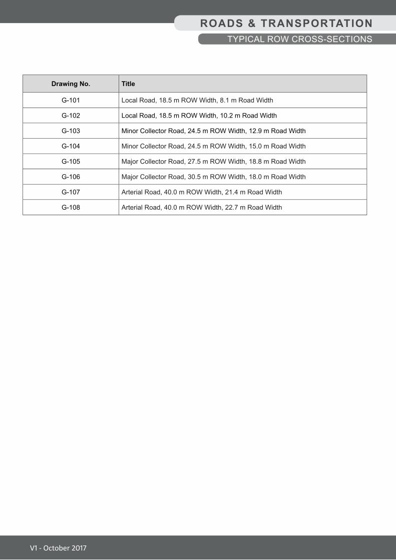
ROADS & TRANSPORTATIONTYPICAL ROW CROSS-SECTIONS
Drawing No. Title
G-101 Local Road, 18.5 m ROW Width, 8.1 m Road Width
G-102 Local Road, 18.5 m ROW Width, 10.2 m Road Width
G-103 Minor Collector Road, 24.5 m ROW Width, 12.9 m Road Width
G-104 Minor Collector Road, 24.5 m ROW Width, 15.0 m Road Width
G-105 Major Collector Road, 27.5 m ROW Width, 18.8 m Road Width
G-106 Major Collector Road, 30.5 m ROW Width, 18.0 m Road Width
G-107 Arterial Road, 40.0 m ROW Width, 21.4 m Road Width
G-108 Arterial Road, 40.0 m ROW Width, 22.7 m Road Width
V1 - October 2017
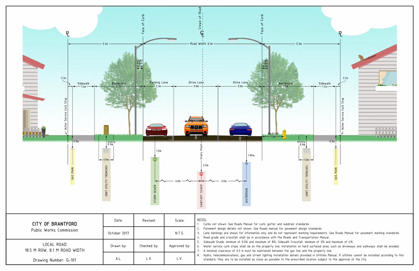
CITY OF BRANTFORDPublic Works Commission
Date: Revised: Scale: NOTES:1. Curbs not shown. See Roads Manual for curb, gutter and subdrain standards.2. Pavement design details not shown. See Roads manual for pavement design standards.3. Lane markings are shown for information only and do not represent marking requirements. See Roads Manual for pavement marking standards.4. Road grade and crossfall shall be in accordance with the Roads and Transportation Manual.5. Sidewalk Grade: minimum of 0.5% and maximum of 8%; Sidewalk Crossfall: minimum of 2% and maximum of 4%.6. Water service curb stops shall be on the property line. Installation on hard surfaced area, such as driveways and walkways shall be avoided.7. A minimum clearance of 0.3 m must be maintained between the gas line and the property line.8. Hydro, telecommunications, gas and street lighting installation details provided in Utilities Manual. If utilities cannot be installed according to this
standard, they are to be installed as close as possible to the prescribed location subject to the approval of the City.
October 2017 N.T.S.
LOCAL ROAD18.5 M ROW, 8.1 M ROAD WIDTH
Drawing Number: G-101
Drawn by: Checked by: Approved by:
A.L. L.V. L.V.
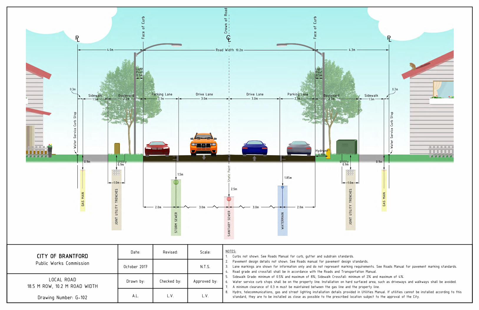
CITY OF BRANTFORDPublic Works Commission
Date: Revised: Scale: NOTES:1. Curbs not shown. See Roads Manual for curb, gutter and subdrain standards.2. Pavement design details not shown. See Roads manual for pavement design standards.3. Lane markings are shown for information only and do not represent marking requirements. See Roads Manual for pavement marking standards.4. Road grade and crossfall shall be in accordance with the Roads and Transportation Manual.5. Sidewalk Grade: minimum of 0.5% and maximum of 8%; Sidewalk Crossfall: minimum of 2% and maximum of 4%.6. Water service curb stops shall be on the property line. Installation on hard surfaced area, such as driveways and walkways shall be avoided.7. A minimum clearance of 0.3 m must be maintained between the gas line and the property line.8. Hydro, telecommunications, gas and street lighting installation details provided in Utilities Manual. If utilities cannot be installed according to this
standard, they are to be installed as close as possible to the prescribed location subject to the approval of the City.
October 2017 N.T.S.
LOCAL ROAD18.5 M ROW, 10.2 M ROAD WIDTH
Drawing Number: G-102
Drawn by: Checked by: Approved by:
A.L. L.V. L.V.
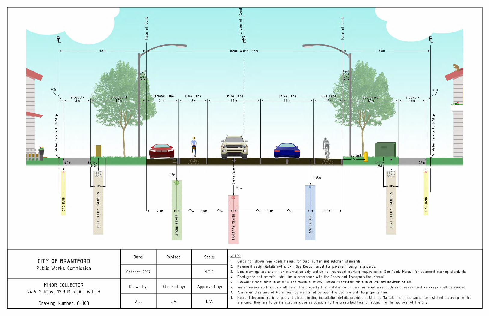
CITY OF BRANTFORDPublic Works Commission
Date: Revised: Scale: NOTES:1. Curbs not shown. See Roads Manual for curb, gutter and subdrain standards.2. Pavement design details not shown. See Roads manual for pavement design standards.3. Lane markings are shown for information only and do not represent marking requirements. See Roads Manual for pavement marking standards.4. Road grade and crossfall shall be in accordance with the Roads and Transportation Manual.5. Sidewalk Grade: minimum of 0.5% and maximum of 8%; Sidewalk Crossfall: minimum of 2% and maximum of 4%.6. Water service curb stops shall be on the property line. Installation on hard surfaced area, such as driveways and walkways shall be avoided.7. A minimum clearance of 0.3 m must be maintained between the gas line and the property line.8. Hydro, telecommunications, gas and street lighting installation details provided in Utilities Manual. If utilities cannot be installed according to this
standard, they are to be installed as close as possible to the prescribed location subject to the approval of the City.
October 2017 N.T.S.
MINOR COLLECTOR24.5 M ROW, 12.9 M ROAD WIDTH
Drawing Number: G-103
Drawn by: Checked by: Approved by:
A.L. L.V. L.V.
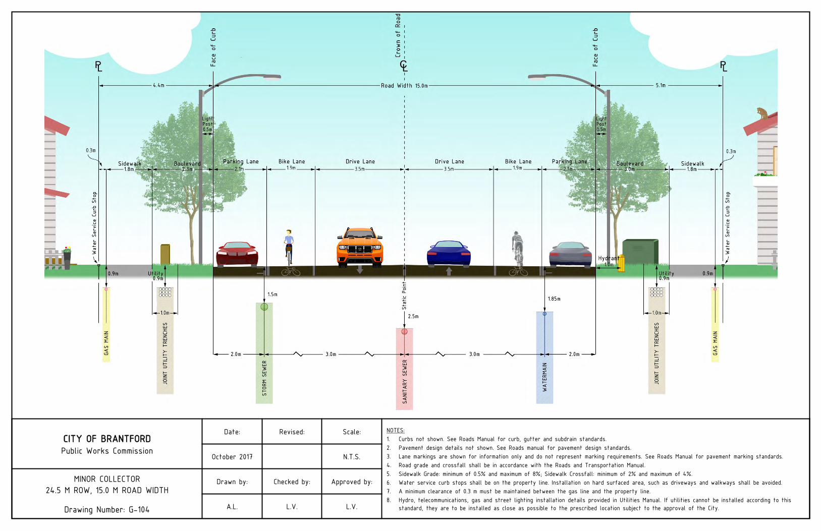
CITY OF BRANTFORDPublic Works Commission
Date: Revised: Scale: NOTES:1. Curbs not shown. See Roads Manual for curb, gutter and subdrain standards.2. Pavement design details not shown. See Roads manual for pavement design standards.3. Lane markings are shown for information only and do not represent marking requirements. See Roads Manual for pavement marking standards.4. Road grade and crossfall shall be in accordance with the Roads and Transportation Manual.5. Sidewalk Grade: minimum of 0.5% and maximum of 8%; Sidewalk Crossfall: minimum of 2% and maximum of 4%.6. Water service curb stops shall be on the property line. Installation on hard surfaced area, such as driveways and walkways shall be avoided.7. A minimum clearance of 0.3 m must be maintained between the gas line and the property line.8. Hydro, telecommunications, gas and street lighting installation details provided in Utilities Manual. If utilities cannot be installed according to this
standard, they are to be installed as close as possible to the prescribed location subject to the approval of the City.
October 2017 N.T.S.
MINOR COLLECTOR24.5 M ROW, 15.0 M ROAD WIDTH
Drawing Number: G-104
Drawn by: Checked by: Approved by:
A.L. L.V. L.V.
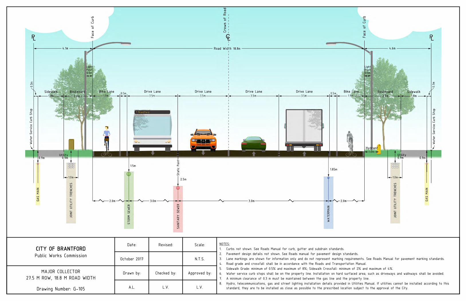
CITY OF BRANTFORDPublic Works Commission
Date: Revised: Scale: NOTES:1. Curbs not shown. See Roads Manual for curb, gutter and subdrain standards.2. Pavement design details not shown. See Roads manual for pavement design standards.3. Lane markings are shown for information only and do not represent marking requirements. See Roads Manual for pavement marking standards.4. Road grade and crossfall shall be in accordance with the Roads and Transportation Manual.5. Sidewalk Grade: minimum of 0.5% and maximum of 8%; Sidewalk Crossfall: minimum of 2% and maximum of 4%.6. Water service curb stops shall be on the property line. Installation on hard surfaced area, such as driveways and walkways shall be avoided.7. A minimum clearance of 0.3 m must be maintained between the gas line and the property line.8. Hydro, telecommunications, gas and street lighting installation details provided in Utilities Manual. If utilities cannot be installed according to this
standard, they are to be installed as close as possible to the prescribed location subject to the approval of the City.
October 2017 N.T.S.
MAJOR COLLECTOR27.5 M ROW, 18.8 M ROAD WIDTH
Drawing Number: G-105
Drawn by: Checked by: Approved by:
A.L. L.V. L.V.
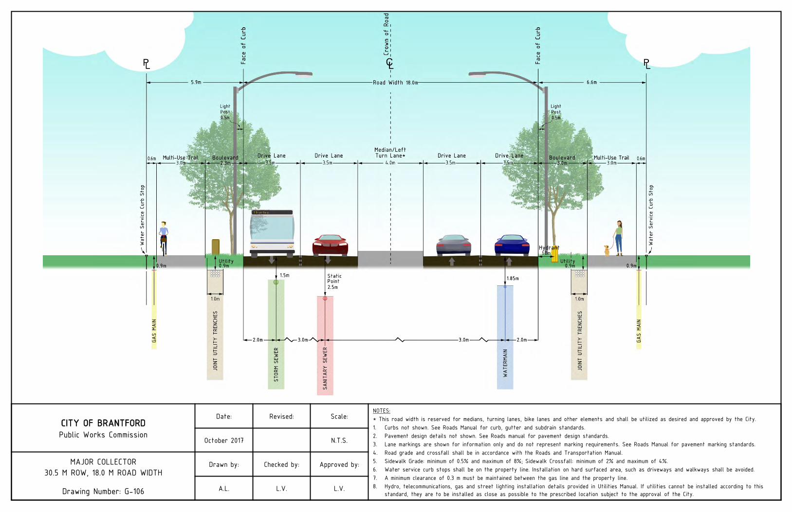
CITY OF BRANTFORDPublic Works Commission
Date: Revised: Scale:NOTES:* This road width is reserved for medians, turning lanes, bike lanes and other elements and shall be utilized as desired and approved by the City.1. Curbs not shown. See Roads Manual for curb, gutter and subdrain standards.2. Pavement design details not shown. See Roads manual for pavement design standards.3. Lane markings are shown for information only and do not represent marking requirements. See Roads Manual for pavement marking standards.4. Road grade and crossfall shall be in accordance with the Roads and Transportation Manual.5. Sidewalk Grade: minimum of 0.5% and maximum of 8%; Sidewalk Crossfall: minimum of 2% and maximum of 4%.6. Water service curb stops shall be on the property line. Installation on hard surfaced area, such as driveways and walkways shall be avoided.7. A minimum clearance of 0.3 m must be maintained between the gas line and the property line.8. Hydro, telecommunications, gas and street lighting installation details provided in Utilities Manual. If utilities cannot be installed according to this
standard, they are to be installed as close as possible to the prescribed location subject to the approval of the City.
October 2017 N.T.S.
MAJOR COLLECTOR30.5 M ROW, 18.0 M ROAD WIDTH
Drawing Number: G-106
Drawn by: Checked by: Approved by:
A.L. L.V. L.V.
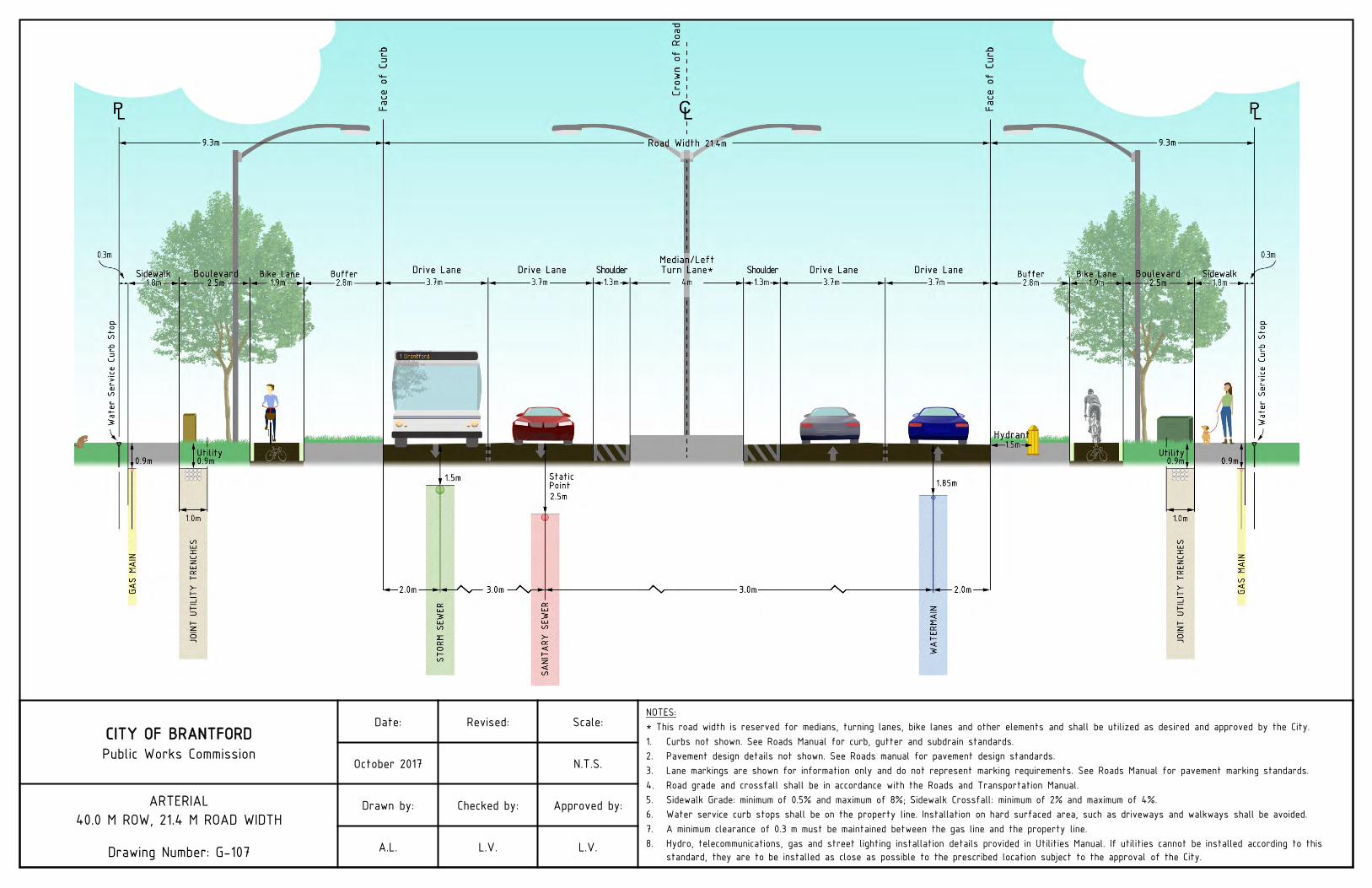
CITY OF BRANTFORDPublic Works Commission
Date: Revised: Scale:NOTES:* This road width is reserved for medians, turning lanes, bike lanes and other elements and shall be utilized as desired and approved by the City.1. Curbs not shown. See Roads Manual for curb, gutter and subdrain standards.2. Pavement design details not shown. See Roads manual for pavement design standards.3. Lane markings are shown for information only and do not represent marking requirements. See Roads Manual for pavement marking standards.4. Road grade and crossfall shall be in accordance with the Roads and Transportation Manual.5. Sidewalk Grade: minimum of 0.5% and maximum of 8%; Sidewalk Crossfall: minimum of 2% and maximum of 4%.6. Water service curb stops shall be on the property line. Installation on hard surfaced area, such as driveways and walkways shall be avoided.7. A minimum clearance of 0.3 m must be maintained between the gas line and the property line.8. Hydro, telecommunications, gas and street lighting installation details provided in Utilities Manual. If utilities cannot be installed according to this
standard, they are to be installed as close as possible to the prescribed location subject to the approval of the City.
October 2017 N.T.S.
ARTERIAL40.0 M ROW, 21.4 M ROAD WIDTH
Drawing Number: G-107
Drawn by: Checked by: Approved by:
A.L. L.V. L.V.
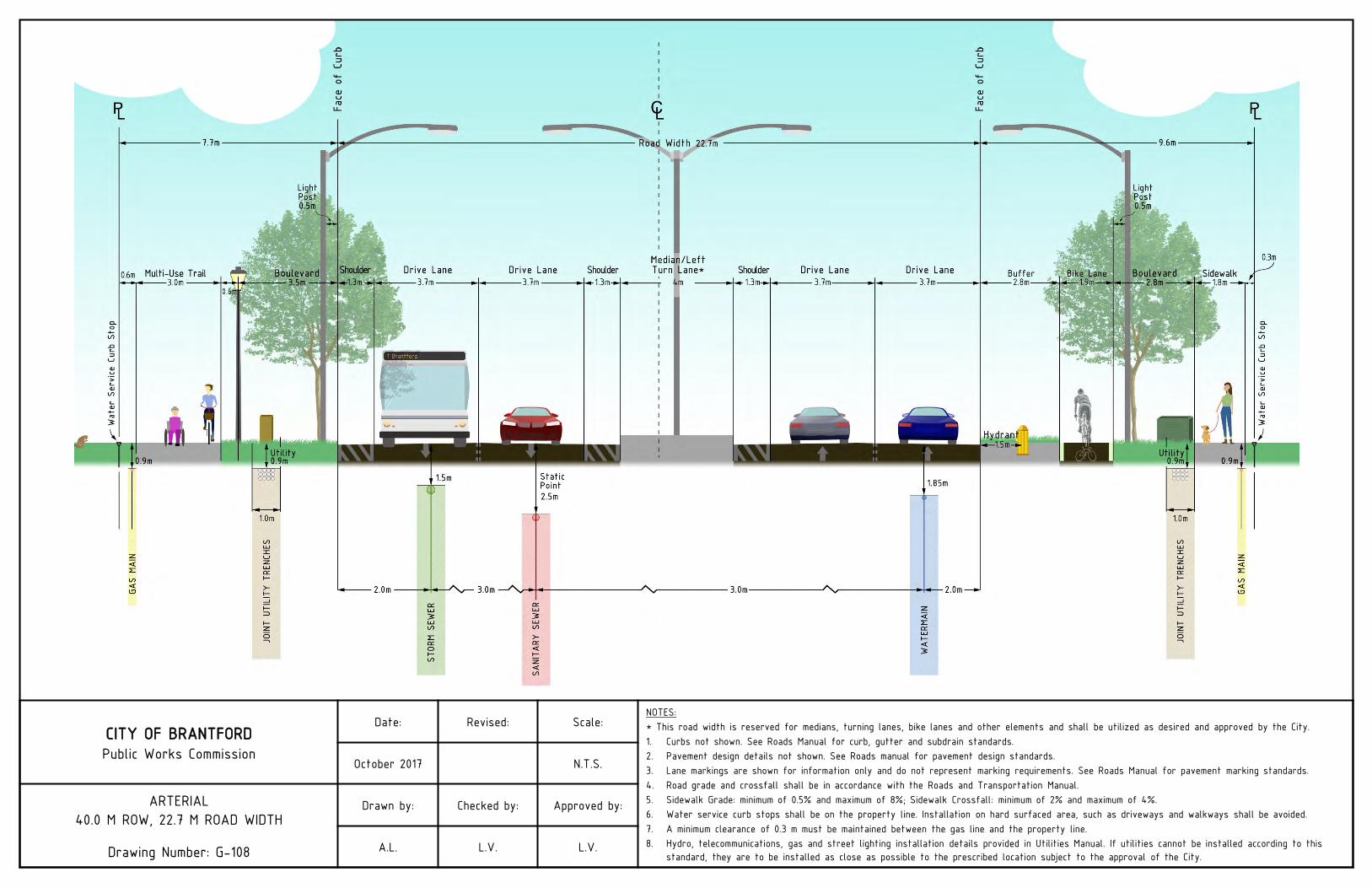
CITY OF BRANTFORDPublic Works Commission
Date: Revised: Scale:NOTES:* This road width is reserved for medians, turning lanes, bike lanes and other elements and shall be utilized as desired and approved by the City.1. Curbs not shown. See Roads Manual for curb, gutter and subdrain standards.2. Pavement design details not shown. See Roads manual for pavement design standards.3. Lane markings are shown for information only and do not represent marking requirements. See Roads Manual for pavement marking standards.4. Road grade and crossfall shall be in accordance with the Roads and Transportation Manual.5. Sidewalk Grade: minimum of 0.5% and maximum of 8%; Sidewalk Crossfall: minimum of 2% and maximum of 4%.6. Water service curb stops shall be on the property line. Installation on hard surfaced area, such as driveways and walkways shall be avoided.7. A minimum clearance of 0.3 m must be maintained between the gas line and the property line.8. Hydro, telecommunications, gas and street lighting installation details provided in Utilities Manual. If utilities cannot be installed according to this
standard, they are to be installed as close as possible to the prescribed location subject to the approval of the City.
October 2017 N.T.S.
ARTERIAL40.0 M ROW, 22.7 M ROAD WIDTH
Drawing Number: G-108
Drawn by: Checked by: Approved by:
A.L. L.V. L.V.

ROADS AND TRANSPORTATION
Standard Drawings
V1 - October 2017 61
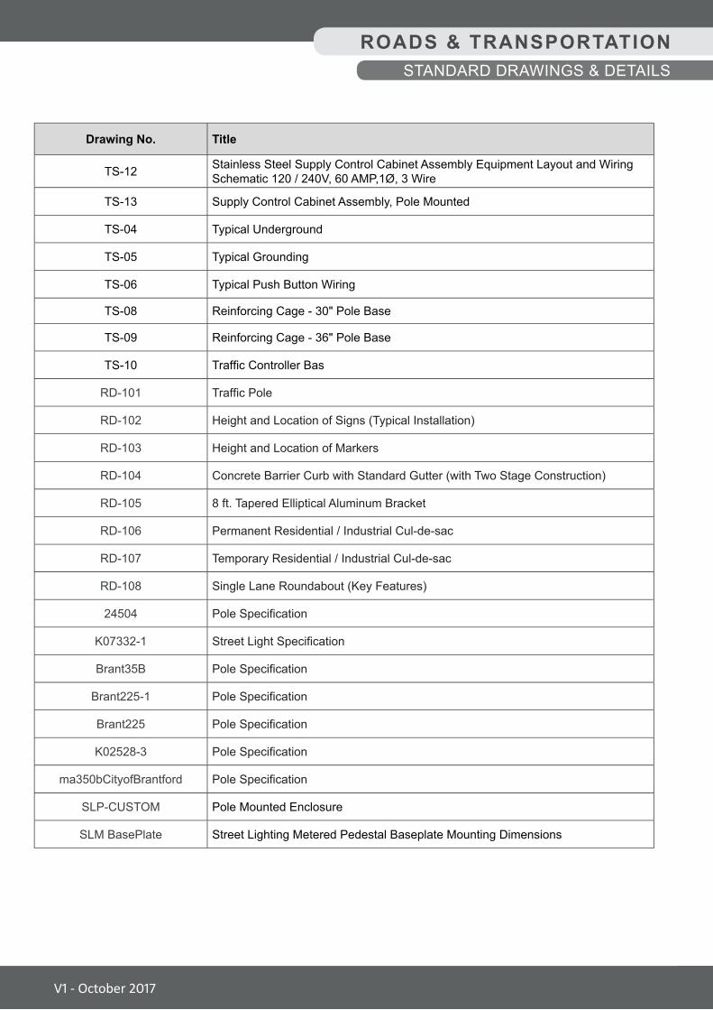
Drawing No. Title
TS-12 Stainless Steel Supply Control Cabinet Assembly Equipment Layout and Wiring Schematic 120 / 240V, 60 AMP,1Ø, 3 Wire
TS-13 Supply Control Cabinet Assembly, Pole Mounted
TS-04 Typical Underground
TS-05 Typical Grounding
TS-06 Typical Push Button Wiring
TS-08 Reinforcing Cage - 30" Pole Base
TS-09 Reinforcing Cage - 36" Pole Base
TS-10 Traffic Controller Bas
RD-101 Traffic Pole
RD-102 Height and Location of Signs (Typical Installation)
RD-103 Height and Location of Markers
RD-104 Concrete Barrier Curb with Standard Gutter (with Two Stage Construction)
RD-105 8 ft. Tapered Elliptical Aluminum Bracket
RD-106 Permanent Residential / Industrial Cul-de-sac
RD-107 Temporary Residential / Industrial Cul-de-sac
RD-108 Single Lane Roundabout (Key Features)
24504 Pole Specification
K07332-1 Street Light Specification
Brant35B Pole Specification
Brant225-1 Pole Specification
Brant225 Pole Specification
K02528-3 Pole Specification
ma350bCityofBrantford Pole Specification
SLP-CUSTOM Pole Mounted Enclosure
SLM BasePlate Street Lighting Metered Pedestal Baseplate Mounting Dimensions
ROADS & TRANSPORTATIONSTANDARD DRAWINGS & DETAILS
V1 - October 2017
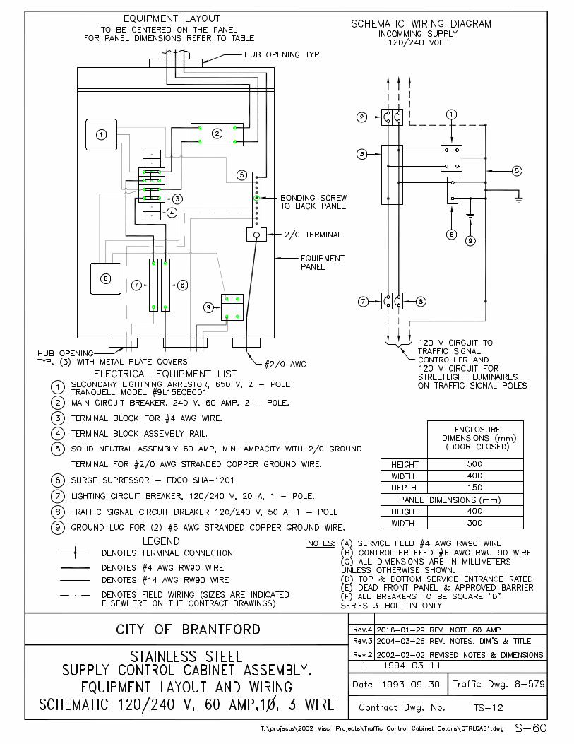
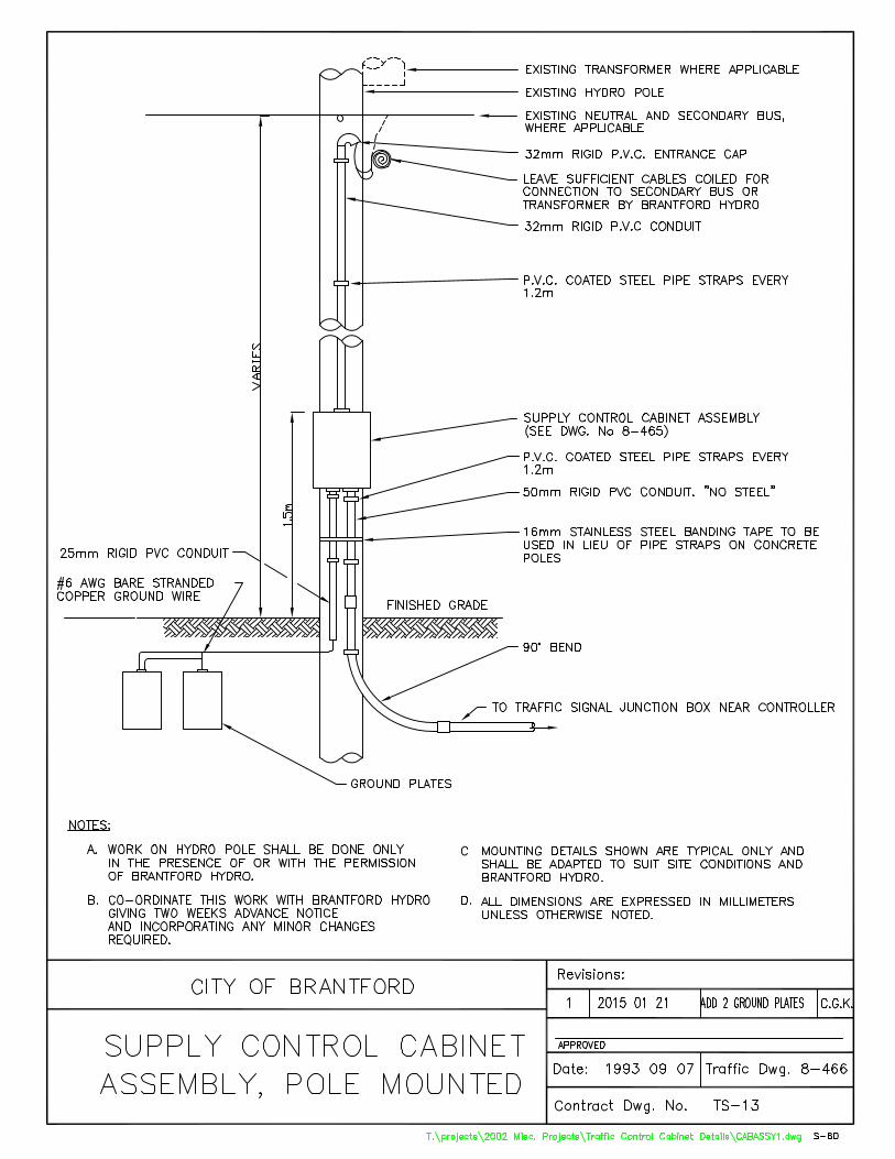
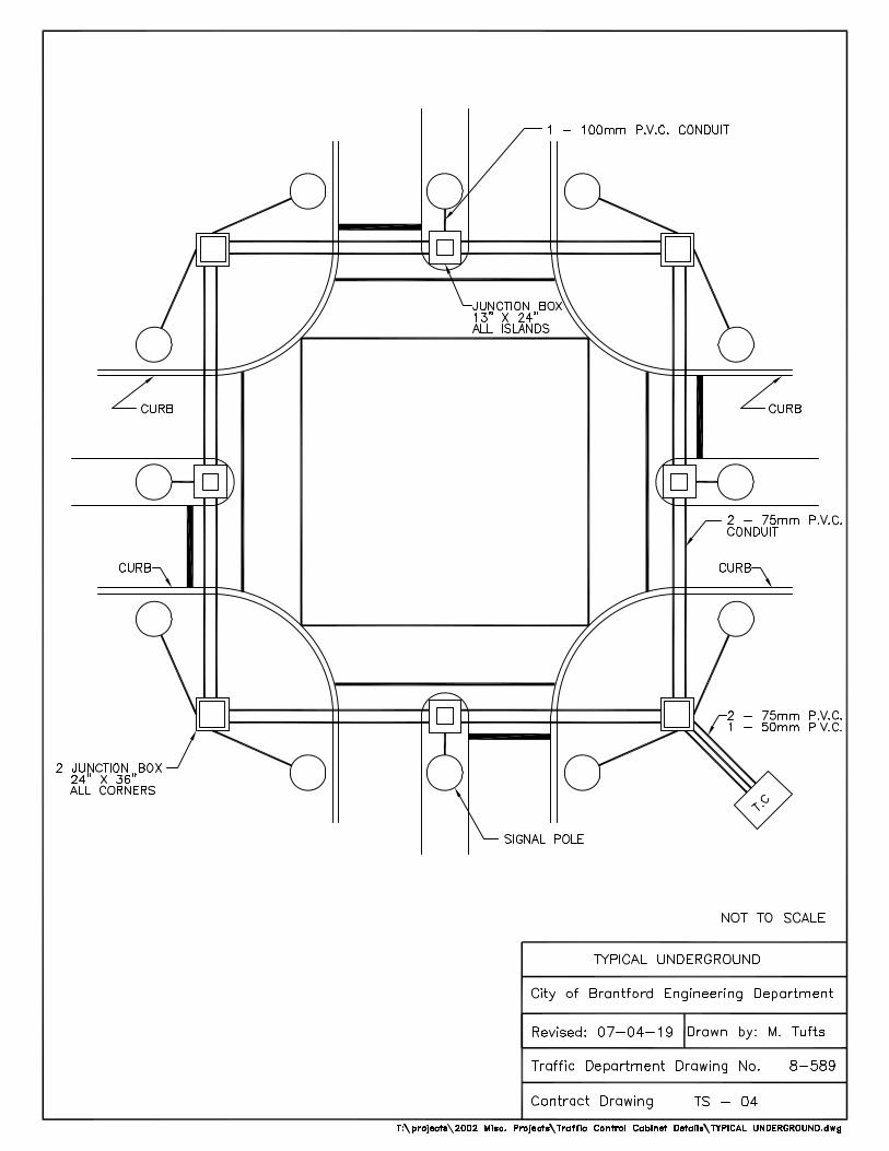
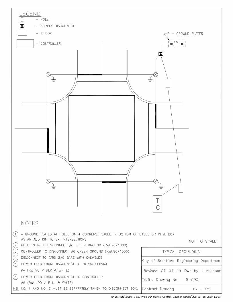
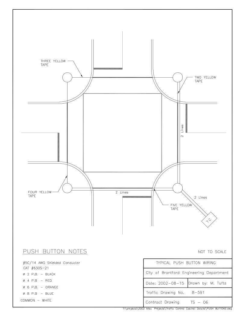
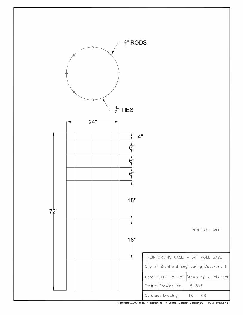
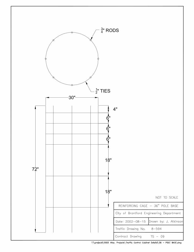
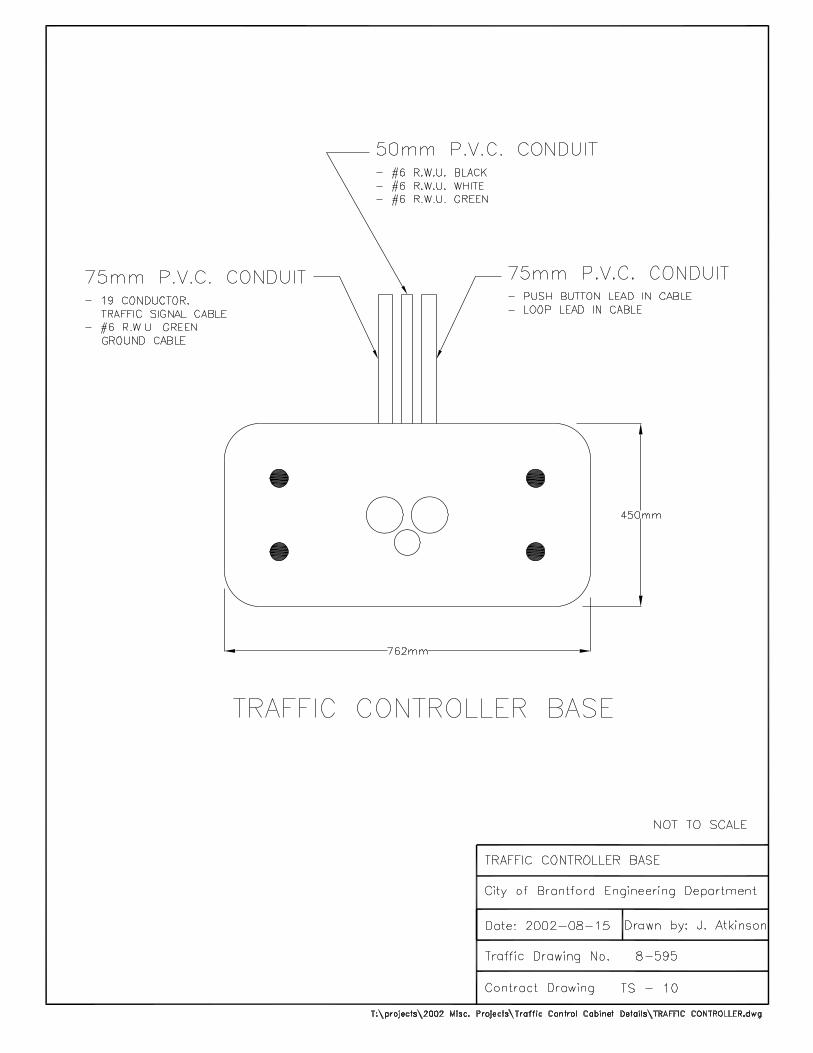
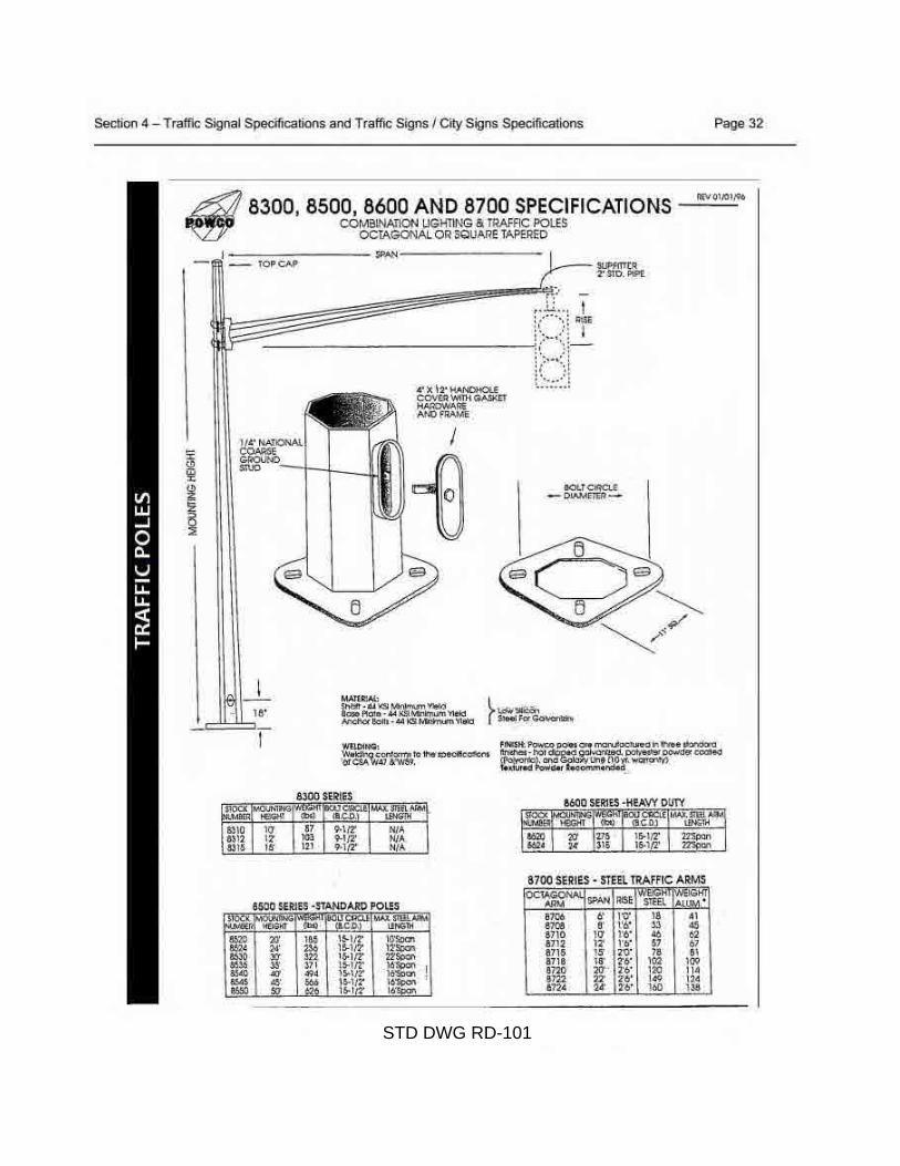
STD DWG RD-101
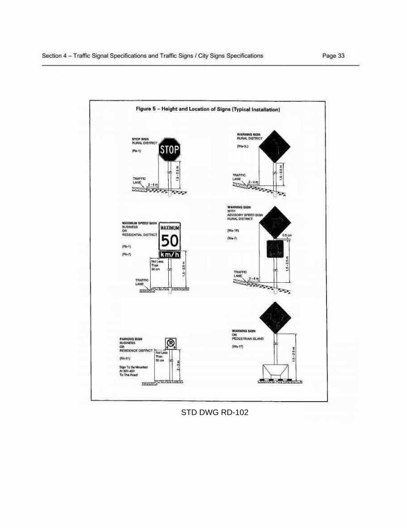
STD DWG RD-102
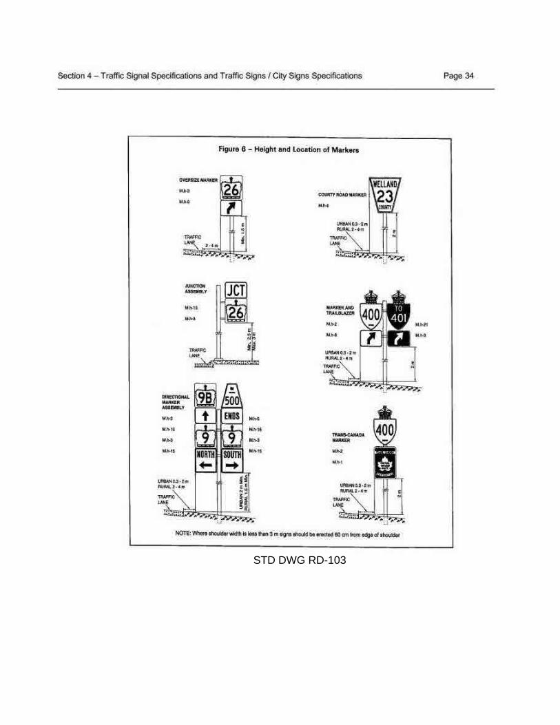
STD DWG RD-103
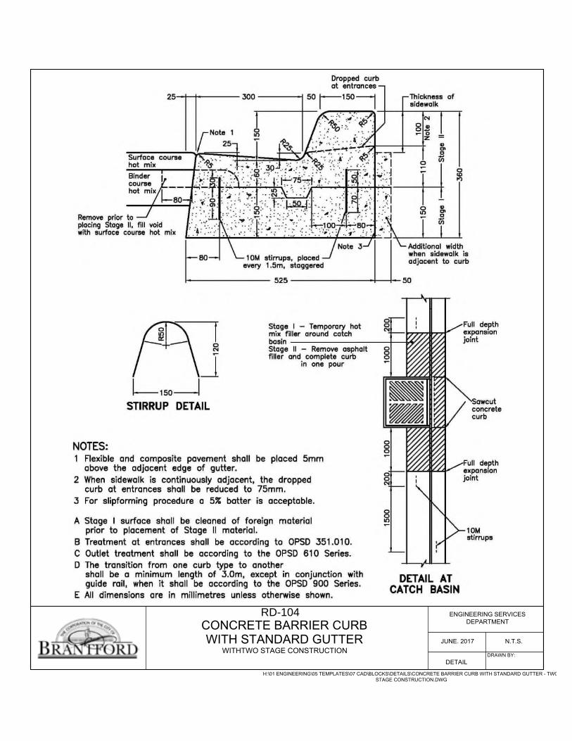
CONCRETE BARRIER CURBENGINEERING SERVICES
DEPARTMENT
JUNE. 2017 N.T.S.
DETAIL
H:\01 ENGINEERING\05 TEMPLATES\07 CAD\BLOCKS\DETAILS\CONCRETE BARRIER CURB WITH STANDARD GUTTER - TWOSTAGE CONSTRUCTION.DWG
DRAWN BY:
WITH STANDARD GUTTERWITHTWO STAGE CONSTRUCTION
RD-104
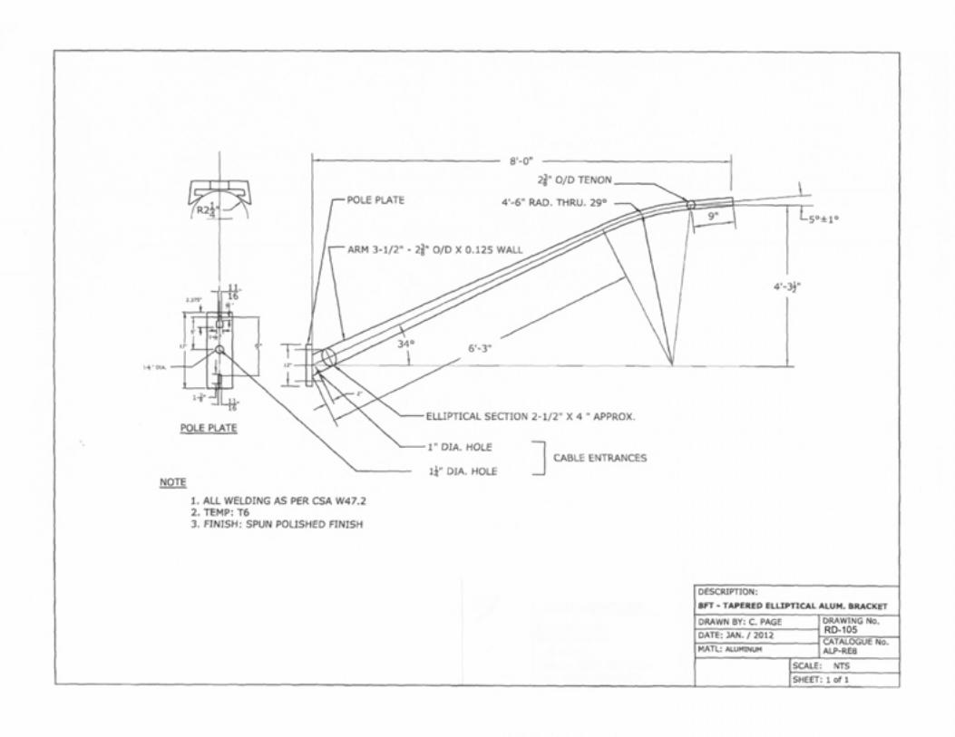
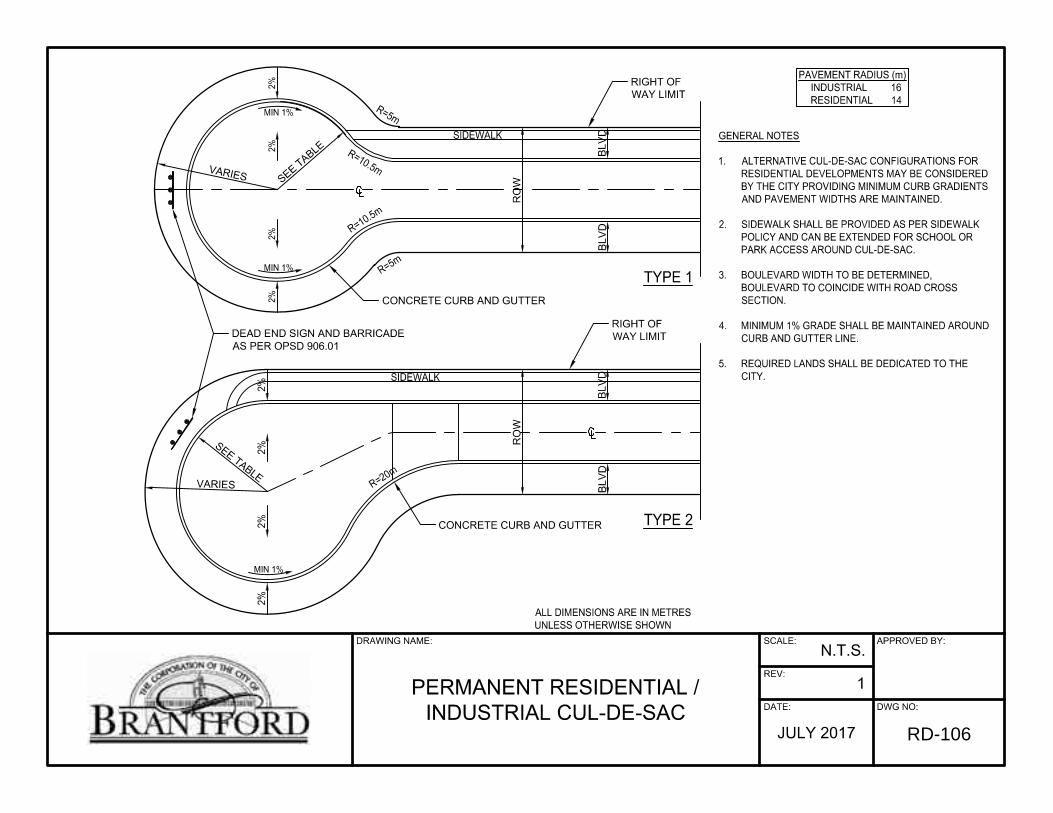
CONCRETE CURB AND GUTTER
CONCRETE CURB AND GUTTER
RO
W
RIGHT OFWAY LIMIT
RIGHT OFWAY LIMIT
DEAD END SIGN AND BARRICADEAS PER OPSD 906.01
SEE TABLEVARIES
SEE TABLE
VARIES
GENERAL NOTES
1. ALTERNATIVE CUL-DE-SAC CONFIGURATIONS FORRESIDENTIAL DEVELOPMENTS MAY BE CONSIDEREDBY THE CITY PROVIDING MINIMUM CURB GRADIENTSAND PAVEMENT WIDTHS ARE MAINTAINED.
2. SIDEWALK SHALL BE PROVIDED AS PER SIDEWALKPOLICY AND CAN BE EXTENDED FOR SCHOOL ORPARK ACCESS AROUND CUL-DE-SAC.
3. BOULEVARD WIDTH TO BE DETERMINED,BOULEVARD TO COINCIDE WITH ROAD CROSSSECTION.
4. MINIMUM 1% GRADE SHALL BE MAINTAINED AROUNDCURB AND GUTTER LINE.
5. REQUIRED LANDS SHALL BE DEDICATED TO THECITY.
PAVEMENT RADIUS (m)INDUSTRIAL 16RESIDENTIAL 14
TYPE 2
TYPE 1
ALL DIMENSIONS ARE IN METRESUNLESS OTHERWISE SHOWN
REV:
SCALE:
DATE: DWG NO:
APPROVED BY:
1
N.T.S.
JULY 2017
DRAWING NAME:
PERMANENT RESIDENTIAL /INDUSTRIAL CUL-DE-SAC
BLV
DB
LVD
R=20m
R=5m
R=10.5m
R=5m
R=10.5m
2%2%
2%2%
2%2%
2%2%
MIN 1%
MIN 1%
MIN 1%
RO
W
BLV
DB
LVDSIDEWALK
SIDEWALK
RD-106
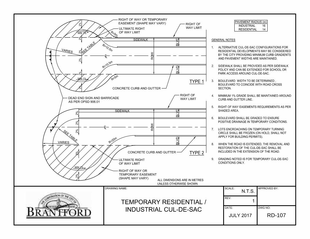
CONCRETE CURB AND GUTTER
RIGHT OF WAY ORTEMPORARY EASEMENT(SHAPE MAY VARY)
CONCRETE CURB AND GUTTER
RIGHT OF WAY OR TEMPORARYEASEMENT (SHAPE MAY VARY)
RO
W
RIGHT OFWAY LIMIT
RIGHT OFWAY LIMIT
DEAD END SIGN AND BARRICADEAS PER OPSD 906.01
SEE TABLEVARIES
SEE TABLE
VARIES
GENERAL NOTES
1. ALTERNATIVE CUL-DE-SAC CONFIGURATIONS FORRESIDENTIAL DEVELOPMENTS MAY BE CONSIDEREDBY THE CITY PROVIDING MINIMUM CURB GRADIENTSAND PAVEMENT WIDTHS ARE MAINTAINED.
2. SIDEWALK SHALL BE PROVIDED AS PER SIDEWALKPOLICY AND CAN BE EXTENDED FOR SCHOOL ORPARK ACCESS AROUND CUL-DE-SAC.
3. BOULEVARD WIDTH TO BE DETERMINED ,BOULEVARD TO COINCIDE WITH ROAD CROSSSECTION.
4. MINIMUM 1% GRADE SHALL BE MAINTAINED AROUNDCURB AND GUTTER LINE.
5. RIGHT OF WAY EASEMENTS REQUIREMENTS AS PERSHADED AREA.
6. BOULEVARD SHALL BE GRADED TO ENSUREPOSITIVE DRAINAGE IN TEMPORARY CONDITIONS.
7. LOTS ENCROACHING ON TEMPORARY TURNINGCIRCLE SHALL BE FROZEN (ON HOLD, SHALL NOTAPPLY FOR BUILDING PERMITS).
8. WHEN THE ROAD IS EXTENDED, THE REMOVAL ANDRESTORATION OF THE CUL-DE-SAC SHALL BEINCLUDED IN THE EXTENSION OF THE ROAD.
9. GRADING NOTED IS FOR TEMPORARY CUL-DE-SACCONDITIONS ONLY.
PAVEMENT RADIUS (m)INDUSTRIAL 16RESIDENTIAL 14
TYPE 2
TYPE 1
ALL DIMENSIONS ARE IN METRESUNLESS OTHERWISE SHOWN
REV:
SCALE:
DATE: DWG NO:
APPROVED BY:
1
N.T.S.
JULY 2017
DRAWING NAME:
TEMPORARY RESIDENTIAL /INDUSTRIAL CUL-DE-SAC
BLV
DB
LVD
R=20m
R=5m
R=10.5m
R=5m
R=10.5m
2%2%
2%2%
2%2%
2%2%
2%2%
2%MIN 1%
MIN 1%
MIN 1%
RO
W
BLV
DB
LVDSIDEWALK
SIDEWALK
ULTIMATE RIGHTOF WAY LIMIT
ULTIMATE RIGHTOF WAY LIMIT
RD-107
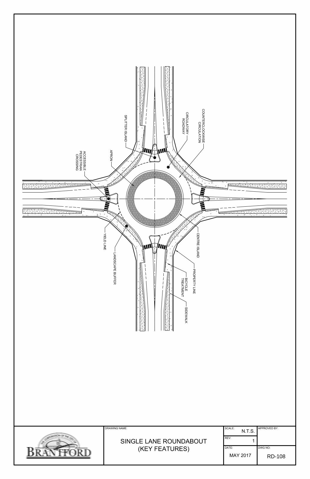
REV:
SCALE:
DATE: DWG NO:
APPROVED BY:
1
N.T.S.
MAY 2017
DRAWING NAME:
SINGLE LANE ROUNDABOUT(KEY FEATURES)
SID
EW
ALK
BIC
YC
LETR
EA
TME
NT
PR
OP
ER
TY LIN
E
LAN
DS
CA
PE
BU
FFER
AC
CE
SS
IBLE
PE
DE
STR
IAN
CR
OS
SIN
G
YIE
LD LIN
E
AP
RO
N
SP
LITTER
ISLA
ND
CIR
CU
LATO
RY
RO
AD
WA
Y
CO
UN
TER
CLO
CK
WIS
EC
IRC
ULA
TION
CE
NTR
E IS
LAN
D
RD-108
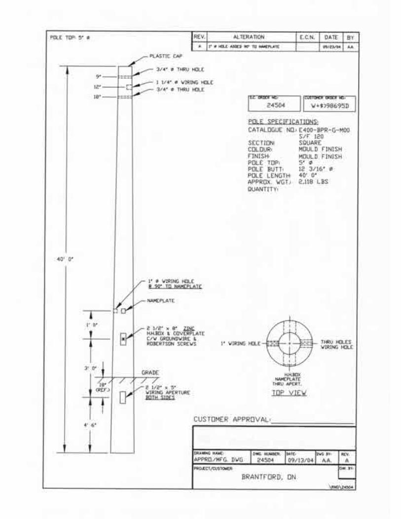
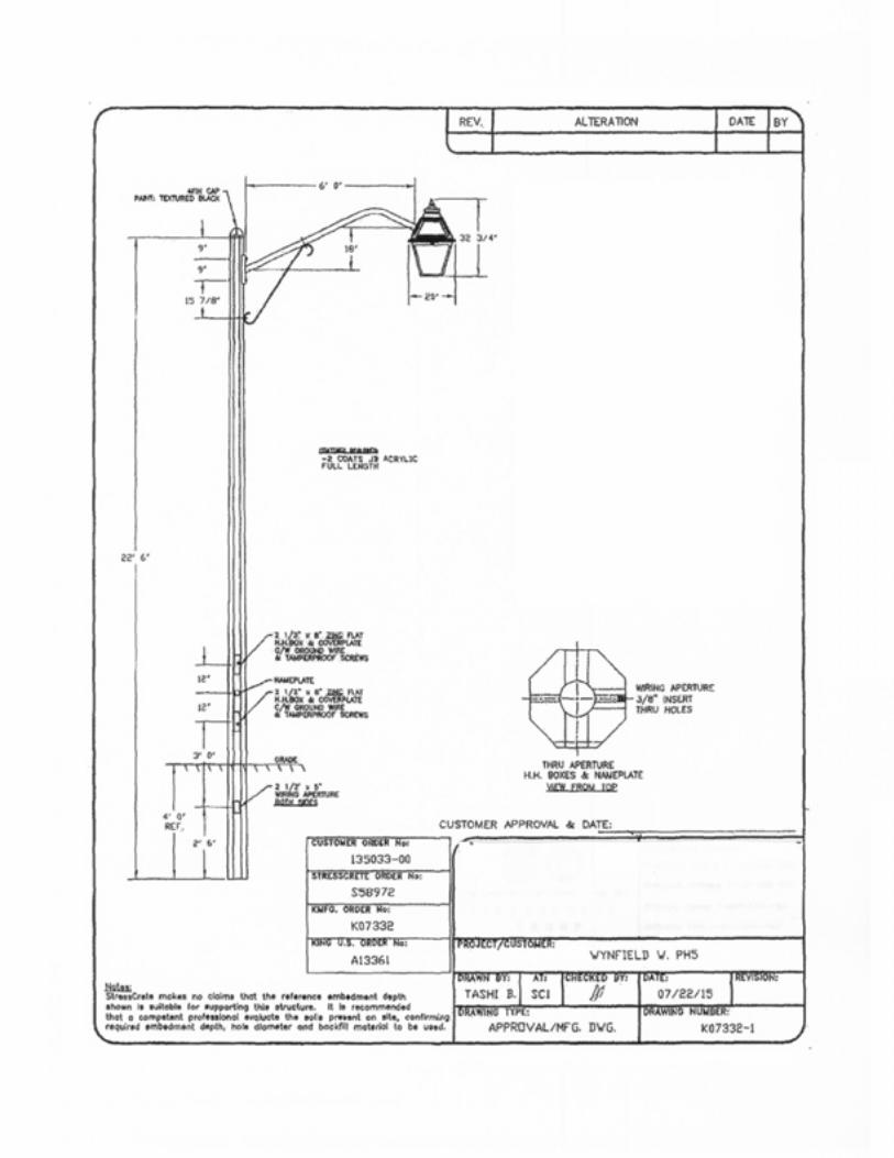
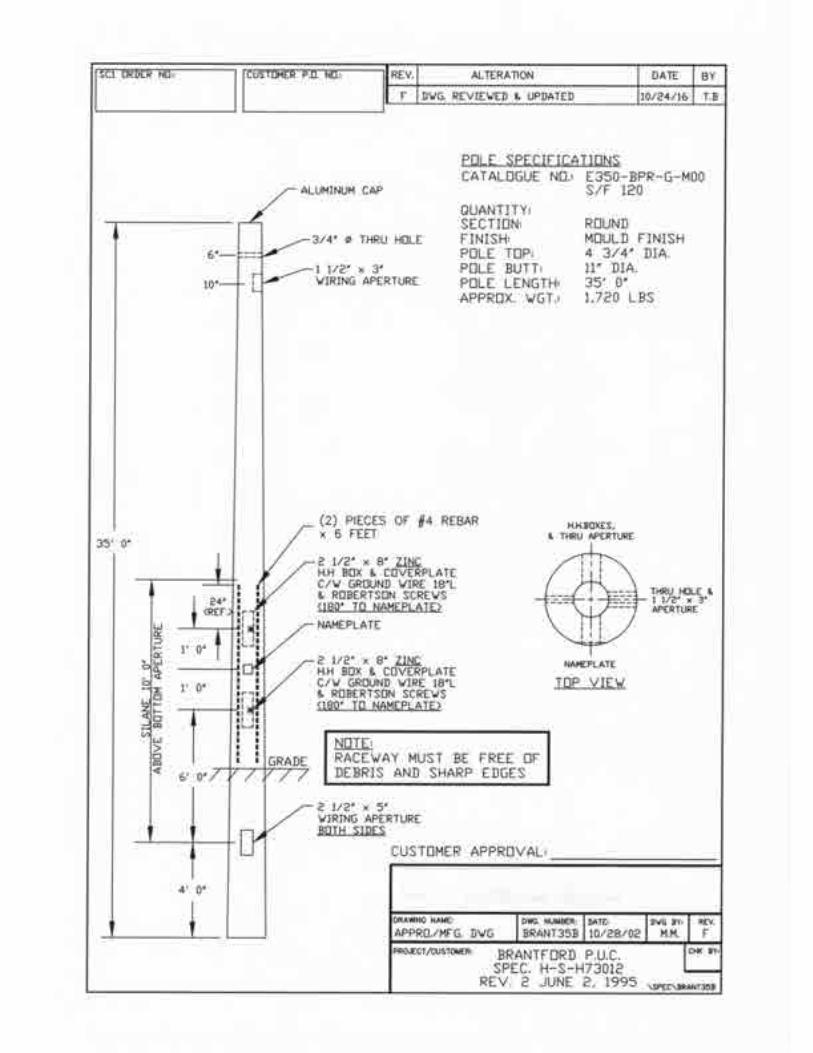
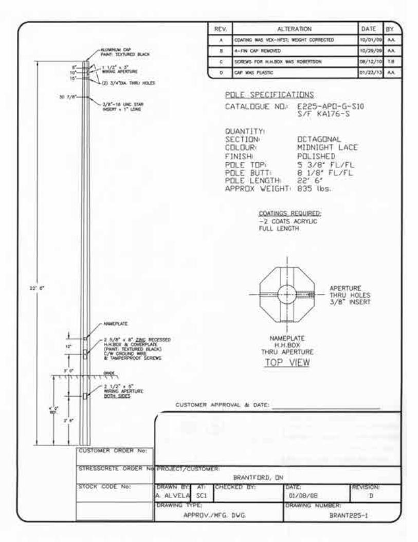
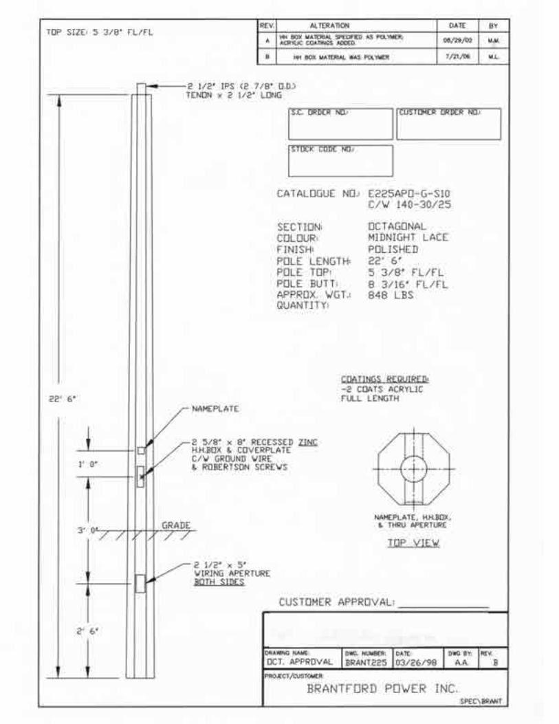
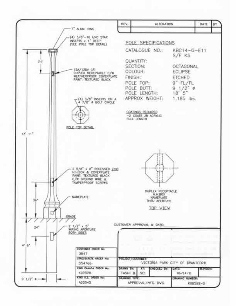
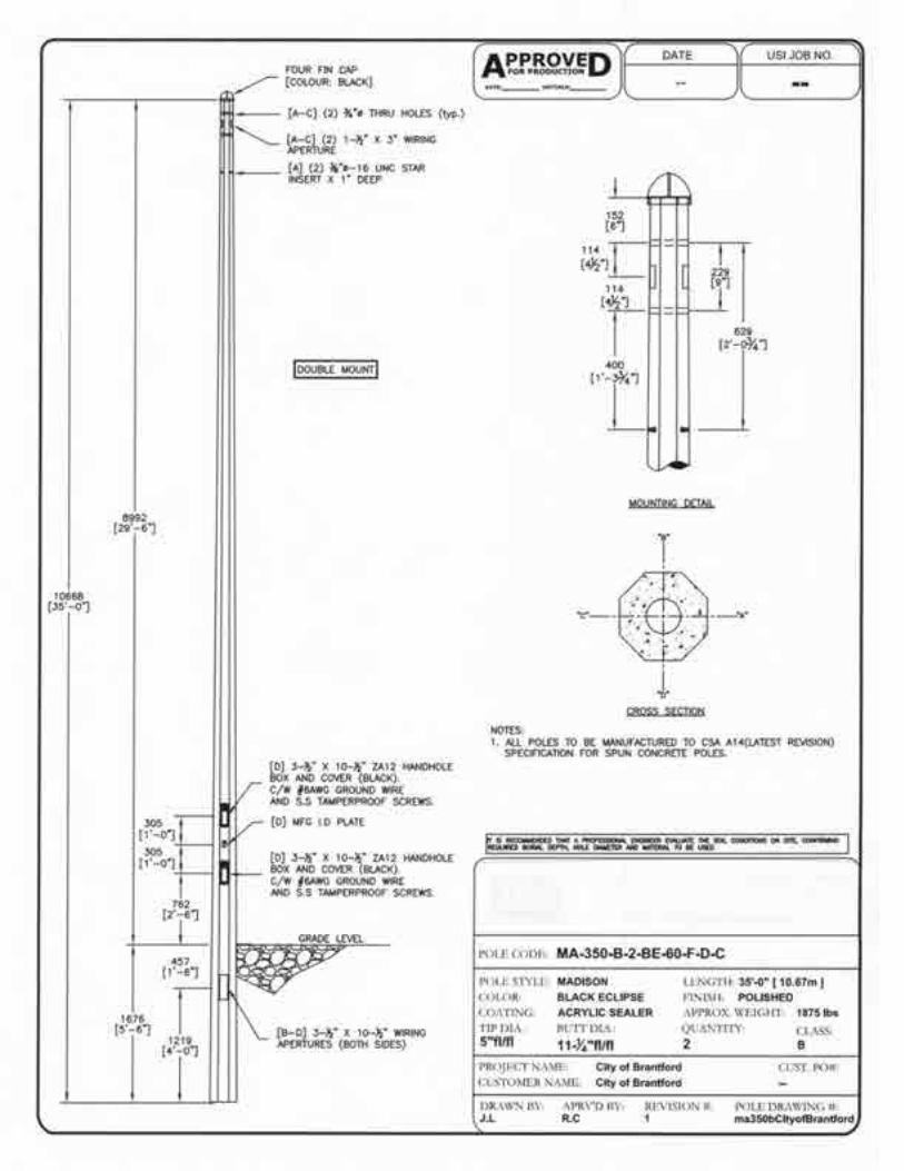
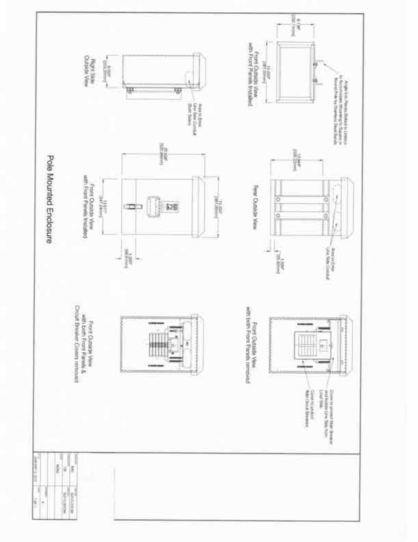
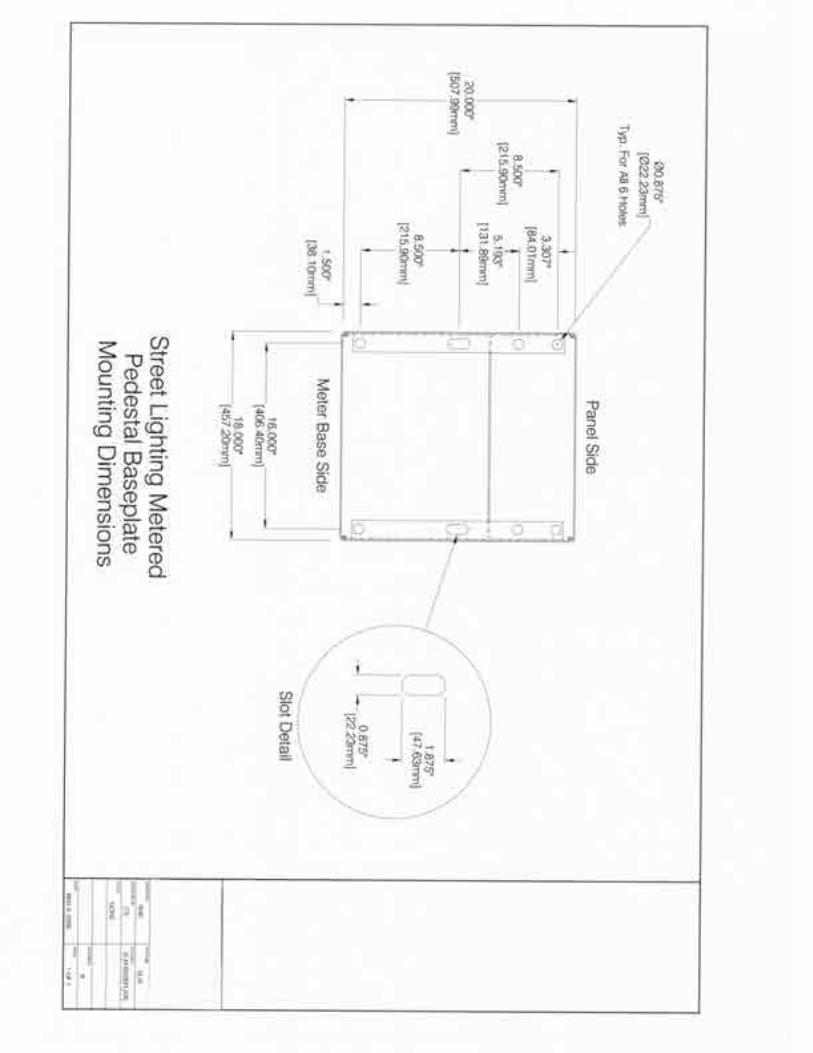

ROADS & TRANSPORTATION
V1 - October 2017 - END ROADS AND TRANSPORTATION -