Embed Size (px)
Citation preview
DEPARTMENT OF INFRASTRUCTURE ENERGY AND RESOURCES
ROAD SAFETY BARRIERS
DESIGN GUIDE
Part B
Transport Infrastructure Branch
i
i i
PURPOSE
Keywords:
Hazard identification, evaluation, performance standards, crash test, end treatments, types of barrier, design process, longitudinal barriers, end treatments, crash attenuators, transitions, maintenance, temporary safety barrier systems.
The purpose of this guide is to provide guidelines for the identification of the need for a road safety barrier, the selection of an appropriate type of barrier, and the design and location of longitudinal barrier systems.
The guide describes the processes used to identify hazards, test proposed safety barrier systems, evaluate treatment options and to design a road safety barrier system, including the choice of end treatments and transitions.
It outlines a set of guidelines rather than a prescriptive set of standards. Therefore, designers should apply the recommended guidelines in conjunction with their own knowledge, experience and judgement to develop the most appropriate treatment for the issue that they are considering. However, every effort should the made to achieve the objectives of the guidelines whenever it is practically feasible.
CONTENTS
6 BRIDGES AND BRIDGE APPROACHES............................................................................................3 7 TRANSITIONS BETWEEN BARRIER TYPES.....................................................................................4
7.1 General.........................................................................................................................................4 7.2 Design Criteria –Physically Connected Barriers ..........................................................................4 7.3 Typical Interfaces between Barrier Types....................................................................................5
8 END TREATMENTS AND CRASH ATTENUATORS ..........................................................................9 8.2 Introduction ..................................................................................................................................9 8.3 Types of End Treatments.............................................................................................................14 8.4 Selection of End Treatments........................................................................................................23 8.5 Terminal Approach and Placement Conditions ...........................................................................25
9 MAINTENANCE OF SAFETY BARRIERS...........................................................................................27 9.2 Introduction ..................................................................................................................................27 9.3 Routine Safety Barrier Maintenance ............................................................................................27 9.4 Repair and Reinstatement ...........................................................................................................28 9.5 Operational Monitoring.................................................................................................................29
10 TEMPORARY SAFETY BARRIER SYSTEMS ....................................................................................30 10.2 Introduction ..................................................................................................................................30 10.3 Purpose and Use of Safety Barriers at Roadwork Sites ..............................................................31 10.4 Types of Longitudinal Safety Barrier Systems for Temporary Use..............................................32 10.5 Operational Requirements for the Use of Barriers at Roadwork Sites ........................................33 10.6 Selection of Safety Barrier Type for Worksites ............................................................................36
REFERENCES ................................................................................................................................................39
i
FIGURES Figure 7.1 — An Example of an Interface between Wire Rope Barrier and W-Beam Barrier ......................... 7 Figure 7.2 — Wire Rope Safety Barrier to Rigid Barrier.................................................................................. 8 Figure 8.1 — Gating and Non-Gating Systems............................................................................................... 11 Figure 8.2 — Redirective and Non-redirective Systems ................................................................................. 13 Figure 8.3 — General Arrangement Modified Eccentric Loader Terminal (MELT)...................................... 16 Figure 8.4 — Non-Proprietary Bull-Nose Treatment...................................................................................... 21 Figure 8.5 — Trailing Terminal ...................................................................................................................... 22 Figure 8.6 — Space Required for Crash Attenuators in Gore Areas............................................................... 24 Figure 8.7 — Grading for Flared Barrier End Treatment................................................................................ 26 Figure 8.8 — Grading for Non-flared Barrier End Treatment ........................................................................ 26
i i
6 BRIDGES AND BRIDGE APPROACHES Safety barriers for bridges shall be designed in accordance with AS 5100:2004 Bridge design. A significant difference between AS 5100:2004 and the former standard HB77 Australian Bridge Design Code is that clauses for both the performance level definition and selection and design of barriers have been completely replaced. A procedure to assist in the determination of barrier performance levels that is based on recently developed AASHTO documentation has been provided.
Appendix B of AS 5100:2004 provides a procedure to assist in the selection of an appropriate bridge barrier performance level related to traffic conditions and the road environment. It is based on risk assessment of the specific site and the cost of providing a barrier system of a specified performance level.
While AS 5100:2004 is focussed on bridge railings, the procedure could be applied to sites on the approaches to bridges and at other (non-bridge) locations along roads where similar conditions exist. The procedure comprises:
a selection method that leads to a recommendation for a low (TL2), regular (TL4) or medium (TL5) performance level barrier
descriptive advice on the assessment of individual medium-risk to high-risk sites, using risk assessment and benefit cost analysis to determine whether a higher performance level barrier should be provided.
The selection method takes into account factors for road type, down grade, curvature, deck height and under-structure conditions, commercial vehicle percentage, and speed environment.
AS 5100:2004 also provides information on barriers for bicycle and pedestrian bridges and for some design elements for bicycle/pedestrian paths as they relate to bridges.
3

7 TRANSITIONS BETWEEN BARRIER TYPES
7.1 General Transitions are used to provide a safe interface whenever it is necessary to change from one type of barrier to another. A satisfactory interface may be achieved by:
Providing a structurally designed and tested physical connection between the systems. The connections are facilitated through “transition sections” of barrier that are designed to provide gradually increasing lateral stiffness and hence continuity of protection for vehicles that impact the barrier in the vicinity of the interface. Transitions can be used only between semi-rigid systems (i.e. steel to steel) or between semi-rigid and rigid systems (i.e. steel to concrete).
Overlapping the barriers by commencing the more rigid system behind the less rigid system.
The purpose of a transition section is to produce a gradual increase in stiffening between the barrier systems so that vehicular pocketing, snagging or penetration is prevented at any position along the transition. The overlapping of the barriers achieves a similar outcome by providing adequate lateral separation between them.
In practice transitions are achieved by:
increasing the rigidity of a W-Beam system by decreasing the post spacing or by using a double thickness of rail (i.e. nested rail), or an additional rail; and/or
transition to a heavier rail (e.g. Thrie-Beam).
Overlapping different types of barrier is only possible where adequate space is available. This may be used for any systems but is the only way of achieving a transition from wire rope barrier to a more rigid barrier.
Specially designed barrier sections or connections are used for situations where W-Beam is to be connected to Thrie-Beam, or where either of these semi-rigid barriers are to be connected to a rigid barrier (refer AS/NZS 3845:1999). The latter situation typically arises on the approach to bridges that have rigid barriers, but may also occur at other locations.
The Federal Highway Administration website provides details of crash tested transitions (http://safety.fhwa.dot.gov/fourthlevel/hardware/listing.cfm?code=long).
7.2 Design Criteria –Physically Connected Barriers The following criteria are important when designing a transition section or connection (AASHTO 2002). Although AASHTO provides this guidance in relation to bridge approaches, the principles apply where any semi-rigid barrier system is connected to a rigid barrier.
The connection point of the two systems must be as strong as the approach barrier to ensure the connection will not fail on impact by pulling out. The use of a cast-in-place anchor or through-bolt connection is recommended.
The transition must be designed to minimise the likelihood of snagging an errant vehicle, including one from the opposing lane on a two-way facility.
When providing a transition section to a bridge railing end, it is highly desirable to taper the bridge railing end behind the approach transition to prevent pocketing on vehicle impact.
The transition should be long enough to ensure that changes in deflection do not occur over a short distance. The change in stiffness from the less rigid barrier to the more rigid barrier, over the transition length, should increase with a high degree of continuity. This may be achieved by reducing the post spacing, strengthening the rail element or a combination of these techniques.
4
As with longitudinal barriers, kerb and slope features must be addressed. The slope between the edge of the road and the barrier should not be steeper than 1 on 10.
Drainage features such as kerbs, kerb inlets, raised inlets or open drains should not be constructed in front of barriers or a transition area, as they may initiate vehicle instability and adversely affect the crashworthiness of the barrier or transition.
7.3 Typical Interfaces between Barrier Types
7.3.1 General AS/NZS 3845:1999 provides detailed illustrations of transitions between semi-rigid and rigid barriers. These transitions have been tested or are deemed to comply with NCHRP (1993). The transitions are achieved through stiffening of the steel safety barrier by the use of special sections and connectors, reduced post spacing and nesting (i.e. two sections of rail, one inside the other) of the beams.
Wire rope safety barriers (WRSBs) are not designed to be connected to semi-rigid or rigid safety barriers or bridge ends. However, WRSB may be transitioned to more rigid barriers provided that the WRSB overlaps the more rigid barrier by an adequate longitudinal distance and the lateral separation is sufficient to accommodate the maximum likely deflection of the WRSB. Such arrangements should enable the two systems to work independently while providing continuous shielding of hazards.
The WRSB manufacturer should be consulted with regard to any proposed design transitions between WRSB and semi-rigid or rigid barriers to seek assurance that they have either been tested or have been otherwise demonstrated to be acceptable. Table 4.6 may be used as a guide to the lateral separation required in overlapping a rigid barrier with a WRSB.
Guidance on various transitions is provided in the following sections.
7.3.2 W-Beam to Thrie-Beam The transition is achieved through the use of a product that bolts to the W-Beam at one end and to the Thrie-Beam at the other end. This transition is 2 m between post centres and is illustrated in Figures F5 and F15 of Appendix F of AS 3845:1999.
7.3.3 W-Beam to Concrete W-Beams are connected to a concrete barrier either through the use of a Thrie-Beam transition (Figure F5 in AS 3845:1999) or by connecting the W-Beam directly to the concrete using an acceptable direct transition (Figure F9 in AS3845:1999). Both treatments provide a structurally sound connection and a smooth and stiffened transition to prevent snagging and pocketing of impacting vehicles.
5
The Thrie–Beam transition involves:
the use of a prefabricated product to connect the W-Beam to the Thrie-Beam (Figure F15 of AS 3845:1999)
the post spacing being reduced from the standard spacing (2 m) to 1 m for five spaces and then to 500 mm for the two spaces prior to the concrete barrier
nesting of the Thrie-Beam over the last 4 m prior to the concrete barrier
the use of a structure connector to bolt the Thrie-Beam into a recess in the concrete barrier (Figure F27 of AS 3845: 1999).
The W-Beam transition (directly to concrete barrier) involves the:
W-Beam being recessed into the concrete barrier to provide a flush barrier face at the connection
transition being strengthened by the post spacing being reduced progressively from the standard spacing (2 m) to 1 m and then 500 mm over the last 10 m of the beam
transition being further strengthened by nesting of the W-Beam over the last 5 m
concrete barrier being flared away from the W-Beam, the latter being stiffened by circular hollow sections bearing on the face of the concrete at the rear of the beam.
7.3.4 Thrie-Beam to Concrete The transition between Thrie-Beam barrier and concrete barrier is achieved through the use of a structure connector, as shown in Figure F27 of AS 3845:1999, which enables the Thrie-Beam to be bolted into a recess in the concrete barrier. Details of the transition are shown in Figure F6 of AS 3845:1999. The Thrie-Beam is stiffened in the manner described in 7.3.3.
7.3.5 Wire Rope Safety Barrier to Semi-Rigid Barrier These transitions involve the wire rope safety barrier (WRSB) overlapping the W-Beam or Thrie-Beam barrier by a nominal longitudinal distance based on site conditions. Where space is available the barriers can be separated laterally so that they operate independently. An alternative acceptable arrangement (refer Figure 7.1) involves a design that ensures that each barrier does not adversely affect the performance of the other.
7.3.6 Wire Rope Safety Barrier to Concrete Barrier The transition between WRSB and concrete barrier also requires a longitudinal overlap and lateral separation adequate to accommodate deflections under impact. This transition has not been tested. However, the principle of having each barrier separated by a distance that should enable them to operate independently under impact is considered to be a sound and safe practice. An example of such a transition is shown in Figure 7.2.
6
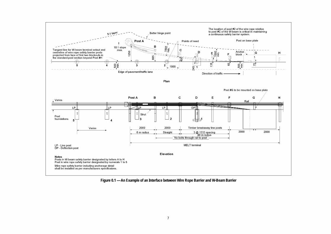
Figure 0.1 — An Example of an Interface between Wire Rope Barrier and W-Beam Barrier
7
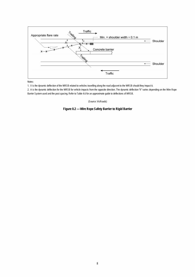
Notes: 1. X is the dynamic deflection of the WRSB related to vehicles travelling along the road adjacent to the WRSB should they impact it. 2. A is the dynamic deflection for the WRSB for vehicle impacts from the opposite direction. The dynamic deflection “X” varies depending on the Wire Rope Barrier System used and the post spacing. Refer to Table 4.6 for an approximate guide to deflections of WRSB.
(Source: VicRoads)
Figure 0.2 — Wire Rope Safety Barrier to Rigid Barrier
8
8 END TREATMENTS AND CRASH ATTENUATORS
8.2 Introduction If not correctly installed barriers are a hazard to road users and this is particularly the case at the ends of barriers. When vehicles impact untreated or incorrectly treated barrier ends they stop abruptly or rollover, or elements of the barrier may penetrate the passenger compartment, with serious consequences for occupants. ‘End Treatment’ (or terminal) is the term applied to devices specifically designed to ensure that the ends of barriers provide safe conditions for occupants of vehicles that may impact this area of a barrier.
The type of end treatment used depends on the barrier. Some treatments function only to provide a safe terminal for the barrier, while others also function as an anchor for the system. The purpose of an end treatment is to protect occupants of a vehicle that impacts the end of a barrier from:
excessive deceleration forces
rails that may spear into the cabin of the vehicle
consequences from possible loss of control of the vehicle.
A crashworthy end treatment must be provided on both the approach and departure ends of barriers that:
terminate within a clear zone
are located in an area where they are likely to be hit head-on by an errant vehicle.
End treatments are used to terminate a safety barrier or to shield fixed roadside hazards such as bridge piers and the ends of road safety barriers in gore areas.
A barrier end treatment may fulfill its function by:
permitting controlled penetration by the vehicle into an area behind the device
decelerating a vehicle to a safe stop within a relatively short distance
containing and redirecting the vehicle
a combination of the above.
End treatments that stop a vehicle within a relatively short distance are called crash attenuators. Commonly used crash attenuators use one of two concepts to absorb the energy of impacting vehicles at a controlled rate. The first is the kinetic energy principle whereby the kinetic energy of an impacting vehicle is absorbed by “crushable” or “plastically deformable” materials or by other energy absorbers. Some of the energy is also dissipated by the crushing of the front end of the colliding vehicle. This type of system requires a rigid back-up or support to resist the collision force of the vehicle, usually in the form of a ground anchor or other linkage backup (such as part of the barrier), or both. This type of system is generally referred to as a compression system. (AASHTO, 2002).
The second concept involves the conservation of momentum principle where the end treatment design involves the transfer of the momentum of an impacting vehicle to an expendable mass (usually sand) located in the vehicle’s path. This type of system is generally referred to as an “inertial barrier” (and may or may not be gating). No rigid backup is required for this type of system, since the energy of the vehicle is not absorbed but transferred to other masses such as sand (AASHTO 2002).
End treatments can be classified as:
Gating or Non-Gating, depending on their behaviour when impacted on the side near the leading end.
9
Redirective or Non-redirective depending on their ability to redirect impacting traffic away from the hazard.
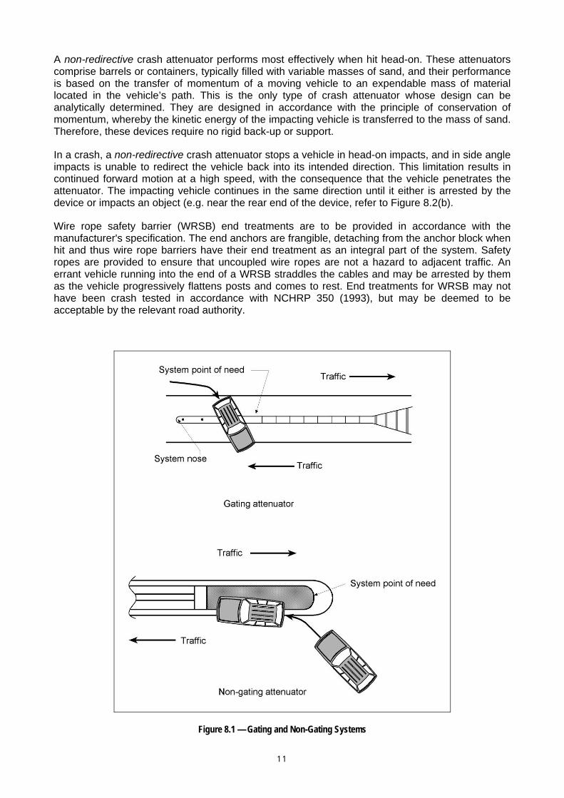
Figure 8.1 illustrates the behaviour of “Gating” and “Non-Gating” systems while Figure 8.2 illustrates the behaviour of redirective and non-redirective systems.
If an errant vehicle can pass through an end treatment beyond the nose and into an area behind the system it is classed as a “gating” terminal. These end treatments are not suitable for use where there is a high potential that an errant vehicle may travel through the end treatment and into a hazard or into opposing traffic lanes (e.g. in narrow medians).
Gating treatments for semi-rigid barriers comprise either a weakened section of W-Beam that hinges or moves out of the way on impact (e.g. MELT terminal), or devices that cause the beam to deform or absorb the kinetic energy of the vehicle. Crash attenuators, designed to be used as a terminal for concrete barriers or to shield other fixed objects, may also be designed to “gate”. For gating end treatments, the ‘length of need’ usually starts about one panel of rail from the impact head of the unit, but this can vary depending on the specific terminal used.
A gating/redirective crash attenuator can function well in both head-on and side angle impacts. The kinetic energy of the vehicle is absorbed by “crushable” or “plastically deformable” materials or by the use of hydraulic energy absorbers placed in front of an obstacle (AASHTO, 2002). Most impact attenuators are based on this concept and need a rigid support to resist the vehicle impact force as the energy-absorbing material is deformed.
When impacted head-on, these impact attenuators have the energy-absorbing ability to slowly bring the vehicle to a safe stop. Angle impacts in the leading section cause the device to “Gate” and, when subjected to glancing or side angle impacts beyond the point of need, they redirect vehicles back into their originally intended direction of travel.
Vehicle that pass through a gating treatment are directed into the area behind the end treatment (i.e. on the side of the barrier opposite the travelled lane). It is therefore necessary to ensure that the lateral slope in this area is 1 on 4 or flatter and is free of any fixed hazards (e.g. poles and trees).
Non-Gating terminals do not allow vehicles to pass through the leading section of the terminal. They either arrest vehicles when they are impacted directly on the end, or redirect them along the travelled way when they are impacted at any point on the side of the barrier. The length of need for a non-gating system is at the nose.
For flexible and semi-rigid barrier types, end treatments must be properly anchored so that the design operational requirements are achieved in practice. Any re-directive capability required by the design will only be achieved by the end treatment developing the same full tensile strength as the barrier upon impact.
1 0
A non-redirective crash attenuator performs most effectively when hit head-on. These attenuators comprise barrels or containers, typically filled with variable masses of sand, and their performance is based on the transfer of momentum of a moving vehicle to an expendable mass of material located in the vehicle’s path. This is the only type of crash attenuator whose design can be analytically determined. They are designed in accordance with the principle of conservation of momentum, whereby the kinetic energy of the impacting vehicle is transferred to the mass of sand. Therefore, these devices require no rigid back-up or support.
In a crash, a non-redirective crash attenuator stops a vehicle in head-on impacts, and in side angle impacts is unable to redirect the vehicle back into its intended direction. This limitation results in continued forward motion at a high speed, with the consequence that the vehicle penetrates the attenuator. The impacting vehicle continues in the same direction until it either is arrested by the device or impacts an object (e.g. near the rear end of the device, refer to Figure 8.2(b).
Wire rope safety barrier (WRSB) end treatments are to be provided in accordance with the manufacturer's specification. The end anchors are frangible, detaching from the anchor block when hit and thus wire rope barriers have their end treatment as an integral part of the system. Safety ropes are provided to ensure that uncoupled wire ropes are not a hazard to adjacent traffic. An errant vehicle running into the end of a WRSB straddles the cables and may be arrested by them as the vehicle progressively flattens posts and comes to rest. End treatments for WRSB may not have been crash tested in accordance with NCHRP 350 (1993), but may be deemed to be acceptable by the relevant road authority.
Figure 8.1 — Gating and Non-Gating Systems
1 1

1 2
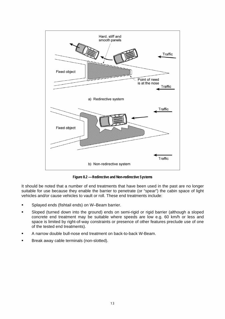
Figure 8.2 — Redirective and Non-redirective Systems
It should be noted that a number of end treatments that have been used in the past are no longer suitable for use because they enable the barrier to penetrate (or “spear”) the cabin space of light vehicles and/or cause vehicles to vault or roll. These end treatments include:
Splayed ends (fishtail ends) on W–Beam barrier.
Sloped (turned down into the ground) ends on semi-rigid or rigid barrier (although a sloped concrete end treatment may be suitable where speeds are low e.g. 60 km/h or less and space is limited by right-of-way constraints or presence of other features preclude use of one of the tested end treatments).
A narrow double bull-nose end treatment on back-to-back W-Beam.
Break away cable terminals (non-slotted).
1 3
8.3 Types of End Treatments 8.3.1 General In many cases safety barriers will have to be terminated relatively close to the edge of the road and end treatments that are non-proprietary products (i.e. public domain under AS/NZS 3845:1999) or proprietary products (i.e. subject to patents) will have to be selected. This section describes the types of gating and non-gating treatments that are available. For each type of end treatment the re-directive characteristics will vary according to the design, material and construction of the treatment and these characteristics should be understood by designers as they must suit the requirements of particular sites.
Where a barrier is located some distance from the edge of the road it may be possible to flare the barrier and terminate it outside of the clear zone. In such cases, because a significant percentage of errant vehicles may travel beyond the clear zone, it is preferable that a crashworthy end treatment is provided. A non-crashworthy end treatment should only be considered where a detailed assessment concludes that the likelihood of an end-on impact with the barrier is very low.
At sites that are unsuitable for a non-proprietary end treatment (e.g. MELT refer section 8.2.2) it will often be necessary to provide a proprietary end treatment. These devices can be relatively expensive and in suitable situations it may be appropriate to terminate a barrier in a cutting face or a back slope. These non-proprietary, buried end treatments can be effective and may be used provided that they are designed and crash tested (including the anchor) to meet the requirements of the appropriate test level (usually TL3). This type of treatment may be appropriate where:
A road passes through a series of cut to fill lines, the cuttings are steep (e.g. say 1V: 0.5H or steeper), smooth and able to redirect vehicles, and barrier is required between the cuttings. This may require the use of a suitably designed end treatment/transition to anchor the barrier (e.g. perhaps in the shape of a concrete barrier), that does not require significant disturbance of the cutting face.
A suitably designed flat-bottomed drain or V drain exists at a site and it is desirable that the safety barrier passes through the drain and is buried in a 1 on 4 back slope (refer section 2.6.4). These terminals have been successfully tested at test level TL3 (refer USA Federal Highways Administration website, FHWA approval letter CC-53 and CC-53A). Key design considerations include:
− the height of the W-Beam should remain constant relative to the roadway grade until the barrier crosses the flow line of the drain
− a flare rate appropriate until the barrier reaches the flow line
− adding a rubbing rail
− using an appropriate anchor (concrete block or steel post) that is capable of developing the full tensile strength of the W-Beam rail.
However, in deciding to adopt this technique designers should be confident that the batter will redirect an errant vehicle and not result in it travelling up the batter and behind the barrier.
As discussed previously, end treatments are defined as being either gating or non-gating.
1 4
8.3.2 Gating End Treatments Gating end treatment systems are designed to breakaway, hinge or pivot when impacted and therefore allow the errant vehicle to pass behind the barrier. They can be non-proprietary (e.g. MELT treatment) or a proprietary product (extruding head terminal).
A gating terminal is considered to have functioned properly if the vehicle remains stable during and after impact and is kept away from the hard point of the barrier system.
Gating terminals must be provided with a hazard free, rectangular-shaped run-out area behind the “gate” and the rail (parallel to the rail) in which vehicles can come to a safe stop (refer Figure 8.3 and AS/NZS 3845:1999). This requirement is based on results of a 97 km/h impact test under the FHWA. The FHWA also notes that the run-out size may not necessarily accommodate all crashes which may occur.
Designers should note that this is a minimum requirement and there are benefits in providing a longer and wider run-out area in the event of an impact with the gating portion of the end treatment.
In constrained circumstances it may not be possible to provide the runout area.
AS/NZS 3845:1999 gives the guidance that if a clear runout is not possible, this area should at least be similar in character to adjacent unshielded roadside areas. In these situations, designers should assess the risk involved with the use of a gating end treatment and no suitable run out area versus other options such as the use of a non-gating end treatment.
The run out area must be suitably graded as shown in Figures 8.7 or 8.8. These figures indicate grading requirements for a parabolic flared end treatment and for a parallel end treatment respectively.
Non-proprietary treatments
Gating end treatments that are acceptable under AS/NZS 3845, and are available in Australia include non-proprietary treatments such as the:
Modified Eccentric Loader Terminal – MELT
Leading Slotted Breakaway Cable Terminal – SBCT
AS/NZS 3845:1999 gives further details on non-proprietary systems.
When these terminals are installed on curves the offset to the terminal (refer Figure 8.3) should not be measured from a tangent to the curve as this will lead to an exaggerated flare rate and high impact angles by errant vehicles. Consequently, the offsets should be measured from the curve.
Modified Eccentric Loader Terminal - MELT
This end treatment is included in AS/NZS 3845:1999. The MELT is considered to offer improved safety, particularly for the smaller Australian passenger car. It has therefore superseded the Breakaway Cable Terminal (BCT) which is no longer used. The general arrangement of the MELT and the run-out area is shown in Figure 8.3.
1 5
The design of the BCT had been tested successfully with vehicles having a mass of 1020 kg and 2000 kg. However, testing with vehicles of 820 kg mass has shown that the BCT was too stiff to buckle readily under reduced energy crashes from this class of vehicle. The vehicles of smaller mass did not develop sufficient kinetic energy to activate the pivoting mechanism and testing showed that this class of vehicle was more susceptible to rotational forces than the larger mass vehicles. In some situations the BCT also resulted in the spearing of vehicles that impacted the system end-on. The BCT is therefore no longer recommended for use.
Under AS/NZS 3845:1999, the MELT is “deemed to comply” although it never passed the testing requirements of NCHRP 350 (1993). In the test the MELT “gated” but the test vehicle hit the rear of the barrier well downstream of the terminal causing it to roll. As a result, even though it did not cause the rollover, the MELT is not installed on new construction on the National Highway System in the USA. However, it did pass the NCHRP 230 testing and existing units can remain in place on US highways.
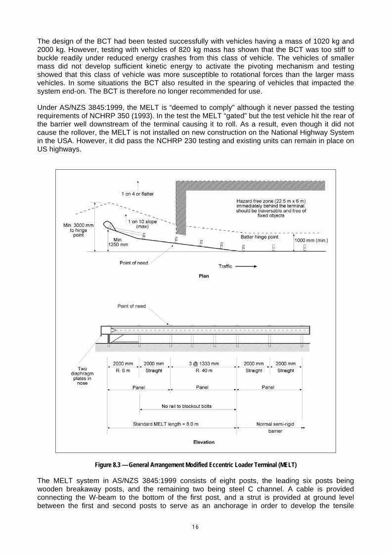
Figure 8.3 — General Arrangement Modified Eccentric Loader Terminal (MELT)
The MELT system in AS/NZS 3845:1999 consists of eight posts, the leading six posts being wooden breakaway posts, and the remaining two being steel C channel. A cable is provided connecting the W-beam to the bottom of the first post, and a strut is provided at ground level between the first and second posts to serve as an anchorage in order to develop the tensile
1 6

strength of the beam so that downstream impacts are redirected. The end of the MELT rail is pre-bent and a buffered end section is installed to prevent spearing. To further impede spearing, the rail is not bolted to the second through sixth posts. This design results in the rail bending and folding away from the traffic lane under impact, although if struck by a vehicle travelling parallel to the traffic lane the impact may cause the curved rail of the MELT to bow towards the traffic lane.
The standard length of a MELT is 12 m, comprising an 8 m section purchased as a MELT from the distributor and a 4 m panel required to connect from the last timber post to the standard W-Beam installation. The maximum cross slope in the departure area should not be greater than 1 on 10. The MELT should only be used with the standard 1.25 m offset of the parabolic flare as any offset flare smaller than this may result in there not being enough kinetic energy in collisions by smaller vehicles to ensure that the terminal's pivot mechanism will activate for all collision angles.
Redirection along the travelled way for a side impact begins at the third post from the approach end. It is at this point that the "length of need" chord may cross the MELT.
Slotted Breakaway Cable Terminal - SBCT
The SBCT is also included in AS/NZS 3845:1999 and is an alternative to the MELT. It has not passed NCHRP 350 (1993) testing but is deemed to comply under AS/NZS 3845:1999. The first five posts of the barrier are weakened timber posts (4 x 20 mm holes 100 mm above ground level) whilst the end section of the barrier rail is slotted in the first two spans and curved on a 40 m radius away from traffic. This weakening of posts and rail enables the terminal to “gate” on impact so that vehicles, including light cars, can pass through the end treatment with an acceptable level of severity.
No blockout is provided on the first post and the blockout and backing plate are omitted on the first intermediate post. The SBCT is similar to the MELT and is illustrated in AS/NZS 3845:1999. It also requires a traversable 22.5 m x 6 m run-out area.
Proprietary Products
Most crash attenuators including those that gate [refer Figure 8-1(a)] are generally patented proprietary products and the manufacturers’ specifications and representative should be consulted to establish the availability of new and improved products that have passed the required testing procedures. In addition, the designer should consult with the relevant road authority to determine specific acceptance criteria relating to new and improved products. Up-to-date information, including in-service reports about crash attenuator features should also be used for the selection/design procedure, it being recognised that specific and highly controlled crash tests are not always adequate indicators of how crash attenuators will perform in different situations.
The number and complexity of factors that enter the selection process for crash attenuators preclude the development of a simple selection procedure. Each operational system has its own unique physical and functional characteristics. In some cases, one crash attenuator will stand out as the most appropriate, but in most cases two or more types will provide satisfactory protection to an errant motorist, and the designer must choose between them (AASHTO 2002). The designer must therefore refer to manufacturers’ specifications and literature to develop a good understanding of the installation requirements of each device and its behaviour under impact, so that the most appropriate product can be selected for any given situation. The Federal Highway Administration (FHWA) web site and approval letters should also be consulted.
Many attenuators provide a “gating” function and use various principles and mechanisms through which a safe end treatment is achieved. In all cases site preparation and the installation of the device must meet the manufacturers’ specifications. In particular, the point of need may vary between products. Products that provide a “gating” terminal may use the following methods of operation.
Displacement of Sand
1 7

The containers are held together (e.g. by cables or other devices) and upon impact the deceleration of the vehicle is controlled through displacement of the sand or liquid. The energy of the vehicle impact is transmitted to the weights of sand in the barrels, thus dissipating the collision energy based on the principle of conservation of momentum. It is essential that the sand used meets specific material grading requirements.
The force of impact is not transmitted through the barrels so backup structures or walls are not required for these systems. The systems can be used as either a crash attenuator placed directly in front of the hazard, or as a barrier end treatment. However, they will not redirect some side crashes, particularly those occurring toward the rear of the installation. Damaged modules must be replaced after each impact.
These systems can be used to protect hazards of any width and are particularly suited to gore areas. They can be used on the left side of the road or in medians. The site must be well compacted and be able to accommodate a concrete or asphalt foundation pad and the transverse slope should not exceed 1 on 20.
Designers should note that the water content (typically 3%) in the sand might freeze if systems are installed in mountainous regions and cold weather continues for several days. In this situation, the attenuators will not work as designed. Mixing rock salt (5 to 25% by volume) with the sand will help reduce the possibility of errant vehicles hitting barrels of frozen sand.
Collapsible Steel Beams and Posts
These systems generally involve a structure of W-Beams, posts and cable anchorages. Collision energy is dissipated by the breaking away of the posts and shearing as W-Beams telescope into each other.
If the first post is damaged in any way, a system may lose its re-directive characteristics. Some systems may also include containers filled with sand, liquid or other crushable material that contribute to the attenuation qualities of the end treatment.
An entire system or some of its components may not be able to be salvaged and used again after a major crash, and nuisance crashes may result in a system not operating as it should.
Deformation of a Steel Beam
These end treatments employ a steel impact head mounted at the leading end of the system. On impact, the head is pushed along the W-Beam, causing the rail to deform, curl around or shred, thus dissipating the collision energy.
These systems require sufficient width in the verge to accommodate the discarded rail sections and it is important to establish whether the rail is extruded onto the traffic side of the system or to the back of the system. An obstacle free area for a distance of 22.5 m beyond the terminal (parallel to the rails) and 6 m behind the rails is generally necessary. Systems may be designed to suit straight or flared barrier alignments.
8.3.3 Non-gating End Treatments General
Most non-gating end treatments are crash attenuators that do not allow a colliding vehicle to pass behind the terminal. On colliding with the end of the terminal, the vehicle will be redirected away from the barrier or be arrested by the barrier.
Because non-gating end treatments do not require a clear, level area behind the barrier, their application is suited to:
median barrier ends where it is important to prevent colliding vehicles from encroaching onto the opposite carriageway
1 8
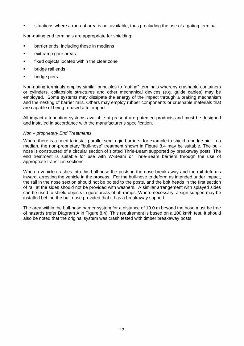
situations where a run-out area is not available, thus precluding the use of a gating terminal.
Non-gating end terminals are appropriate for shielding:
barrier ends, including those in medians
exit ramp gore areas
fixed objects located within the clear zone
bridge rail ends
bridge piers.
Non-gating terminals employ similar principles to “gating” terminals whereby crushable containers or cylinders, collapsible structures and other mechanical devices (e.g. guide cables) may be employed. Some systems may dissipate the energy of the impact through a braking mechanism and the nesting of barrier rails. Others may employ rubber components or crushable materials that are capable of being re-used after impact.
All impact attenuation systems available at present are patented products and must be designed and installed in accordance with the manufacturer's specification.
Non – proprietary End Treatments
Where there is a need to install parallel semi-rigid barriers, for example to shield a bridge pier in a median, the non-proprietary “bull-nose” treatment shown in Figure 8.4 may be suitable. The bull-nose is constructed of a circular section of slotted Thrie-Beam supported by breakaway posts. The end treatment is suitable for use with W-Beam or Thrie-Beam barriers through the use of appropriate transition sections.
When a vehicle crashes into this bull-nose the posts in the nose break away and the rail deforms inward, arresting the vehicle in the process. For the bull-nose to deform as intended under impact, the rail in the nose section should not be bolted to the posts, and the bolt heads in the first section of rail at the sides should not be provided with washers. A similar arrangement with splayed sides can be used to shield objects in gore areas of off-ramps. Where necessary, a sign support may be installed behind the bull-nose provided that it has a breakaway support.
The area within the bull-nose barrier system for a distance of 19.0 m beyond the nose must be free of hazards (refer Diagram A in Figure 8.4). This requirement is based on a 100 km/h test. It should also be noted that the original system was crash tested with timber breakaway posts.
1 9

Proprietary Products
Non-gating crash attenuators are also available for use in situations where it is not desirable to allow vehicles to pass through the nose section of the attenuator. They are generally patented and the manufacturers’ specifications and representative should be consulted to establish the availability of new and improved products that have passed the required testing procedures. In addition, the designer should consult with the relevant road authority to determine specific acceptance criteria relating to new and improved products,
As is the case for gating proprietary products (refer Section 8.2.2) designers must refer to manufacturers’ specifications and literature for non-gating proprietary products to develop a good understanding of the installation requirements of each device and its behaviour under impact. This should ensure that the most appropriate product and design is used for any given situation.
The point of need for non-gating attenuators is at the nose.
2 0
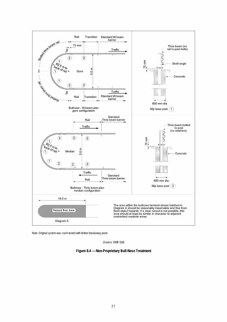
Note: Original system was crash tested with timber breakaway posts
(Source: DMR Qld)
Figure 8.4 — Non-Proprietary Bull-Nose Treatment
2 1
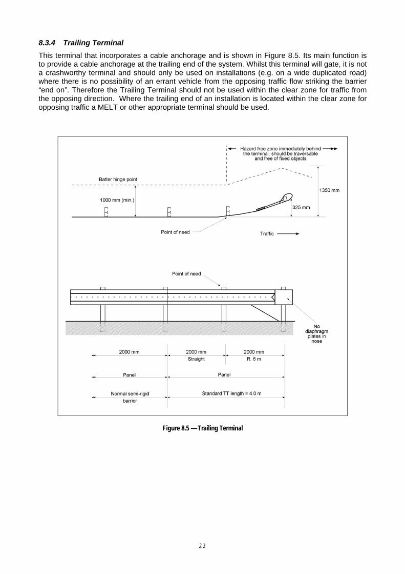
8.3.4 Trailing Terminal This terminal that incorporates a cable anchorage and is shown in Figure 8.5. Its main function is to provide a cable anchorage at the trailing end of the system. Whilst this terminal will gate, it is not a crashworthy terminal and should only be used on installations (e.g. on a wide duplicated road) where there is no possibility of an errant vehicle from the opposing traffic flow striking the barrier “end on”. Therefore the Trailing Terminal should not be used within the clear zone for traffic from the opposing direction. Where the trailing end of an installation is located within the clear zone for opposing traffic a MELT or other appropriate terminal should be used.
Figure 8.5 — Trailing Terminal
2 2
8.4 Selection of End Treatments 8.4.1 General The selection of the most appropriate crashworthy end treatment for a barrier should take the following factors into account:
end treatment’s gating characteristics
end treatment’s re-directive characteristics
speed environment
space available for installation and deformation of the terminal
width required for accommodation and deformation of the terminal
capacity to absorb nuisance crashes
compatibility with barrier type
cost and maintenance factors.
Factors that are important in selection of an end treatment are further discussed below.
8.4.2 Speed Environment The end treatments and crash attenuators discussed may have been tested for different speeds. The selected barrier end should be suitable for the speed environment at the location. Particular end treatments and different configurations of the same crash attenuator will be suitable for particular speed environments. The speed limit is usually taken to represent the speed environment as it provides a practicable relationship to barrier test speeds. The length of some crash attenuators can be varied depending on the speed environment and likely maximum impact speed. Manufacturers’ advice should be sought.
8.4.3 Space Availability The space available for the end treatment will also influence the type to be installed. For instance, some crash attenuators are more suited for use in narrow medians while others are suitable to shield wider hazards. Some crash attenuators and end treatments such as the MELT may require a large run-out area free of hazards for gating of the end, while others may require space to accommodate displacement of the attenuator clear of traffic. Consideration may be given to selecting a physically smaller system on the basis that a smaller size will reduce the number of crashes, especially nuisance crashes, thereby reducing the maintenance that must be undertaken following an incident.
The space requirements of crash attenuators to shield non-removable fixed objects should be considered during all stages of road design and construction (e.g. preliminary design for new works or rehabilitation of existing roads). This will ensure compatibility between the final design and the crash attenuator that is to be installed. Figure 8.6 shows the area that should be made available for crash attenuator installation. However, the information provided in the table is generic and should therefore only be used for planning purposes. Detailed product information should be used for design purposes. Although the figure depicts a gore location, the same recommendations will generally apply to other types of fixed objects that require shielding (AASHTO 2002). However, it is important that the installation complies with all of the manufacturers’ recommendations with respect to space.
Crash attenuators should be orientated so that they face the most likely direction of impact. This is particularly important where the approach is on a tight curve, a situation that may be encountered in construction zones.
2 3
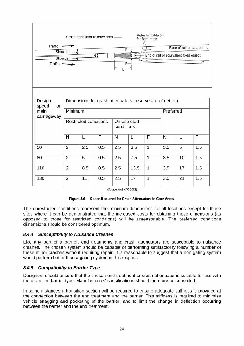
Dimensions for crash attenuators, reserve area (metres)
Minimum
Restricted conditions Unrestricted conditions
Preferred
Design speed on main carriageway
N L F N L F N L F
50 2 2.5 0.5 2.5 3.5 1 3.5 5 1.5
80 2 5 0.5 2.5 7.5 1 3.5 10 1.5
110 2 8.5 0.5 2.5 13.5 1 3.5 17 1.5
130 2 11 0.5 2.5 17 1 3.5 21 1.5
(Source: AASHTO 2002)
Figure 8.6 — Space Required for Crash Attenuators in Gore Areas.
The unrestricted conditions represent the minimum dimensions for all locations except for those sites where it can be demonstrated that the increased costs for obtaining these dimensions (as opposed to those for restricted conditions) will be unreasonable. The preferred conditions dimensions should be considered optimum.
8.4.4 Susceptibility to Nuisance Crashes Like any part of a barrier, end treatments and crash attenuators are susceptible to nuisance crashes. The chosen system should be capable of performing satisfactorily following a number of these minor crashes without requiring repair. It is reasonable to suggest that a non-gating system would perform better than a gating system in this respect.
8.4.5 Compatibility to Barrier Type Designers should ensure that the chosen end treatment or crash attenuator is suitable for use with the proposed barrier type. Manufacturers’ specifications should therefore be consulted.
In some instances a transition section will be required to ensure adequate stiffness is provided at the connection between the end treatment and the barrier. This stiffness is required to minimise vehicle snagging and pocketing of the barrier, and to limit the change in deflection occurring between the barrier and the end treatment.
2 4
8.4.6 Cost and Maintenance Factors In selecting an end treatment for a barrier system a designer should take into account the whole of life cost associated with the treatment including:
capital costs
maintenance costs
risks associated with maintenance repair times.
Crash attenuators are relatively costly to install and to repair after impact, so they are generally used only where it is likely that errant vehicles will hit a hazard with severe consequences, and either:
it would be very difficult or costly to remove or relocate the hazard, make it frangible, or realign the traffic path away from the hazard
there is insufficient room for a normal barrier and its terminals, or normal barrier ends would form unacceptable hazards, (e.g. in some narrow medians).
Site preparation costs to accommodate some systems can be significant. At locations where frequent hits are expected, life cycle costs for repairing or replacing an attenuator system may be a significant factor in the selection process.
The repair and replacement time for an attenuator system following an impact is also an important consideration as this can cause significant losses to road users through delays. The direct costs associated with worker safety and traffic management also need to be considered.
8.5 Terminal Approach and Placement Conditions As end treatments are designed and tested on flat and level terrain with a vehicle impacting at normal height, it is imperative that these conditions be replicated in practice. Failure to do so may result in the device failing to perform as intended. Crash attenuators must therefore be placed on a relatively flat surface and the path between the road and the attenuator must be clear of any irregularities or obstructions, such as excessive slopes or kerbs. These features can cause a vehicle to become airborne and ride over the barrier or rollover on impact. Maximum crossfalls are recommended for various terminal installations.
Energy absorbing attenuators must be placed on a hard, smooth pad or surface, usually constructed of concrete. Although a paved surface is not necessary for inertial systems it does provide an appropriate, low maintenance area and uniform support for the sand barrels.
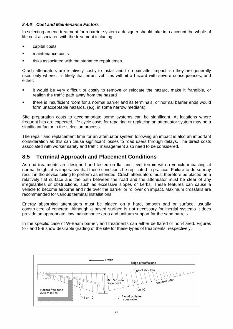
In the specific case of W-Beam barrier, end treatments can either be flared or non-flared. Figures 8-7 and 8-8 show desirable grading of the site for these types of treatments, respectively.
2 5
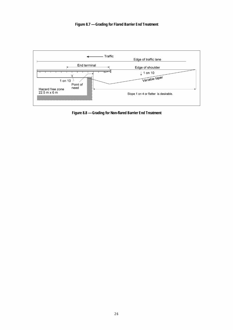
Figure 8.7 — Grading for Flared Barrier End Treatment
Figure 8.8 — Grading for Non-flared Barrier End Treatment
2 6
9 MAINTENANCE OF SAFETY BARRIERS
9.2 Introduction The maintenance costs of barriers should be included in any economic assessment of the type of barrier to be installed. This is particularly important at locations where impacts are likely to occur frequently or be severe.
The level of maintenance required is often an important factor in relation to the occupational health and safety of road maintenance workers and the convenience and safety of road users during the period when barriers are being repaired. This is particularly the case on high-speed, high-volume urban freeways where the width available for works is often limited, works are usually very disruptive to traffic flow, and may be located in highly hazardous locations. In these situations the cost of traffic control and the risk of other collisions occurring during the maintenance operations are significant factors.
Wire rope safety systems require maintenance after even minor impacts, semi-rigid barriers can remain in service after moderate impacts and rigid barriers require virtually no maintenance after significant impacts. Maintenance time and cost is an important factor, but only one factor in selection of a barrier. Capital cost, the severity of impact, and the continuing integrity of the barrier pending maintenance are also important.
The cost of maintaining a barrier to preserve its functional integrity is influenced by the cost of replacement parts and the labour-intensive nature of the operation. It follows that standardisation of details and components will help to minimise maintenance costs. The cost of maintenance work, particularly repair work, on barriers may easily exceed the initial installation cost, especially in the more vulnerable locations. Therefore, it is essential to include the potential maintenance costs in the economic assessment of alternative barrier designs and site-specific barrier types.
Safety barrier products continue to evolve within the service life of current installations. Although replacement of outdated components may be desirable, it is not practicable in terms of other safety priorities and budgetary constraints. Provided that they are in an acceptable condition, are able to meet their original performance standards, and do not include identified hazardous features, superseded components may be maintained until it is economically viable to replace them. Safety barriers including end treatments that have identified hazardous features should be replaced as soon as practicable.
9.3 Routine Safety Barrier Maintenance 9.3.1 General Routine maintenance is generally directed at the long-term upkeep of the barrier installation to ensure the retention of those properties of the system that allow it to fulfil its intended function. Therefore maintenance personnel, as well as construction personnel, should be fully briefed on the salient features and operational characteristics of the type of installation used, so that they do not inadvertently omit or alter some important component.
2 7
Routine maintenance includes:
tensioning of cable anchors
removal of rectangular washers from the heads of bolts holding rails to blockouts or posts (whilst this is not strictly a routine maintenance activity, incorrect aspects of installation should be rectified when a section of barrier is being repaired)
ensuring that all bolts have been installed correctly, especially splice bolts
correction of the rotation, shrinking or splitting of blockouts
treatment of the tops of posts
checking post deterioration due to rotting, including the buried section, and longitudinal splitting
correction of the effect of embankment settlement on the installation (i.e. cross fall in front of the barrier and barrier height.
While undertaking routine maintenance other remedial treatments (e.g. upgrading of end treatments) may be considered.
9.3.2 Installation Measures All barriers must be installed in accordance with AS/NZS 3845:1999, the requirements of manufacturers of proprietary products, and any relevant road authority specifications. Measures that may be adopted at the installation stage to minimise or simplify routine maintenance include:
specifying an acceptable tolerance on anchor cable tension
replacing timber posts and blockouts with corrosion resistant steel or using unpainted, galvanised components throughout, provided that the system with the steel posts has been suitably crash tested
replacing the ground surrounding the post with an encasement of granular material that permits suppression of fungal attack
using thoroughly seasoned high durability timber, free from oblique grain and gum veins
protecting timber post tops with a durable moisture resistant coating (e.g. petroleum jelly).
These measures should also be incorporated when replacement or major servicing of safety barriers becomes necessary.
9.3.3 Related Factors Maintenance work can be made simpler and cheaper if the barrier is located so that it allows access for machinery to maintain roadside areas, or provides adequate space between the installation and fixed obstructions for workmen and/or machinery to operate effectively.
The coexistence of the barrier with other assets, such as underground cables and conduits, is relevant to maintenance operations if there is a risk of one of these assets being damaged while repairing the other. This means that investigation of the locations of underground services is just as important for the determination of barrier position as it is for any other aspect of road design (e.g. drainage, signal foundations).
9.4 Repair and Reinstatement 9.4.1 Cost Factors Impact repair costs for barriers can be significantly influenced by factors relating to the:
type, and section, of the installation struck by a vehicle
2 8
vehicle type, impact speed and angle of impact
location of the installation with respect to the adjacent roadway and the nature of the road
degree to which terminals are affected
availability of replacement items.
9.4.2 Installation Measures Characteristics that facilitate the progress of repair work are:
correct installation in accordance with relevant specifications
use of standard, or matchable, components
post embedment in non-bound materials
proper embedment of posts to the correct depths
replacement using correct posts that also ensure adequate strength and quality
use of the correct bolts and nuts (e.g. galvanised)
avoidance of excessively curved lengths of rail which may require precise shop-curving.
9.5 Operational Monitoring Monitoring of barriers in the field is the best way to determine the performance of a barrier under particular situations. These observations and feedback by maintenance contractors and staff will identify any problems that may occur with the system, and should ensure optimal performance for future installations.
The Australian Standard on safety barriers (AS/NZS 3845:1999) requires that post-crash evaluations be carried out. After crashes into barrier systems, the following considerations should be addressed, as a minimum:
Did the system function as designed?
Should the system be repaired, as it was pre- crash?
If not, which upgrade measures should be carried out to improve the safety of the hazard?
It is noted that AS/NZS 3845:1999 suggests that an action plan for maintenance of safety barrier systems should include these assessment criteria.
2 9
10 TEMPORARY SAFETY BARRIER SYSTEMS
10.2 Introduction This section provides guidance on the use, selection and location of temporary barriers that are used in situations where a permanent barrier is inappropriate. Temporary barriers are used in situations where protection is required for a limited time. Examples include:
roadworks sites (most common application)
protection of infrastructure works on land adjacent to the road and associated work space
special events where there is a need to control vehicle and pedestrian movements.
With respect to roadworks, occupational health and safety is an important aspect in the management of road systems. Apart from personal injury and grief, it has serious implications with respect to increasing litigation and insurance costs. Against this background there is a heightened awareness of Workplace Health and Safety requirements, and the potentially hazardous environment in which road workers have to perform their duties.
Contributing to these hazards is increasing traffic volumes, larger vehicles and in some cases higher speeds through and adjacent to work sites. Inappropriate speed limits or operating speeds can also increase the risk for road users, both during and after worksite operating hours. Where long-term construction sites are created, enforcement of speed can be a problem even with active police participation. While publicity campaigns and enforcement (often utilising radar devices and speed cameras) may assist, generally these measures are outside the control of the personnel on a construction site.
Audits of construction sites have highlighted deficiencies that exist in work zone barrier systems and indicated a lack of knowledge about safety barriers and their fundamental design (Muthusamy and Kumar 1995). Some of the problems identified included:
installations that are too short to shield errant vehicles from the hazard
embankment approaches to barriers that are too steep to ensure that the barrier will be effective
ineffective end treatments
inadequate clearance to workers or hazards in order to cater for the dynamic deflection of the barrier under vehicle impact.
In some cases incorrect or inappropriate practices that have not led to any known problems on previous projects may be repeated. Construction and maintenance managers, engineers, supervisors and workers must therefore take an active role in ensuring that work sites are safe for workers and road users. It is particularly important that where safety barriers are necessary they are used in a consistent and appropriate way. This can only be achieved if relevant personnel are educated and trained to have knowledge of relevant guides and standards, and experience in their application. It is equally important that designers focus on guiding traffic safely through work sites by:
the development of effective temporary traffic management plans including adequate standards for sidetracks and deviations for traffic within sites
3 0
provision of effective and well-maintained signs and markings (including regulatory signs, warning signs, guide signs and delineation) that meet the requirements of AS 1742.3, Manual of uniform traffic control devices (MUTCD), Part 3: Traffic control devices for works on roads.
It is very important that temporary barriers are located so that they do not place road users at risk by restricting sight distance for traffic entering, crossing or moving through the worksite. Care must also be taken to ensure that drainage is adequate so that stormwater does not form ponds adjacent to the barrier and or flow across the road at a depth that could cause vehicles to aquaplane.
The guidelines in this section cover the types of temporary safety barriers currently available and how and when they should be used to enhance safety, both for workers and traffic passing through work sites. The principles also apply to temporary barriers used for other works or activities adjacent to roads, and for traffic control for major events.
10.3 Purpose and Use of Safety Barriers at Roadwork Sites The Australian Standard AS/NZS 3845:1999, Road Safety Barrier Systems defines a temporary road safety barrier system to be “a device designed to be erected and dismantled quickly, used to prevent vehicular access into construction or maintenance work zones. Its purpose is to redirect an impacting vehicle so as to minimise damage to the vehicle and injury to the occupants, while providing worker protection”.
Temporary safety barriers are therefore used to contain and redirect errant vehicles so as to prevent them from leaving the roadway and/or entering the worksite. Like permanent barriers, they should only be used if they reduce the severity and adverse consequences of potential crashes, as they are a hazard in themselves. As well as enhancing site safety, they may improve job productivity and reduce road user delays. They are used in situations where it is considered that traffic volumes, traffic speeds, and the nature of the work (e.g. worksite/traffic separation and duration of the works) indicate that it is both desirable and practical to provide such additional protection. Only temporary barriers that have been successfully crash tested to the same level required of permanent barriers shall be used to shield worksites.
Specifically, temporary safety barriers may be used to:
provide positive protection for workers from vehicles entering the worksite
protect critical construction works such as bridge false work from vehicle impact
prevent traffic from entering work areas where hazards such as trenches, material stockpiles or construction plant could endanger road users
separate opposing traffic where temporary traffic diversions or sidetracks may lead to potential vehicle conflict
minimise road user delays by negating the need for worksite speed limits.
As temporary safety barriers and most permanent safety barriers are not designed to contain large trucks the use of temporary barriers does not necessarily negate the need for reduced speed limits adjacent to construction areas. Reduced speed limits are often implemented on high-speed, high-volume roads, particularly those carrying high numbers of large vehicles and where workers perform duties immediately behind barriers. In determining whether a safety barrier is required, the designer should address the following questions:
3 1
Can the speed of vehicles be maintained at such a value through the work site that, in combination with worker/roadside hazard clearance and the quality of the traffic arrangements (traffic control, road surface/alignment, etc.,) the risk of injury to either workers or road users is consistent with good practice and the requirements of health and safety legislation?
As a temporary barrier has to cater for the highest speed environment that applies during its deployment, what is the traffic speed likely to be outside of construction hours?
Bearing in mind the duration of the particular works and the space available to locate safety barriers, is it practical to install safety barriers?
Is the consequential effect of a vehicle striking construction features such as bridge false work such that protection must be provided?
In view of the nature and duration of the particular work, the speed of vehicles through the site, and the clearance between such traffic and workers/roadside hazards, would the use of safety barriers improve the safety of both workers and road users and should they therefore be provided?
10.4 Types of Longitudinal Safety Barrier Systems for Temporary Use Work site safety barriers can be permanent type installations, or temporary installations that are more readily relocated. Permanent systems may be used where the particular road works site requires shielding for a relatively long period and it is cost effective to provide a barrier. The cost of installing and removing permanent concrete barriers is prohibitive, but there may be a case for the use of semi-rigid permanent barriers depending on site and project characteristics.
Generally barriers used for road works will be of a temporary type to suit the relatively short duration that they are required, the need to move them in accordance with construction and traffic staging requirements, and because of the economic advantages. The following section outlines some types of temporary barrier systems that are available. Other types of temporary systems may be available or under development.
Temporary safety barriers that are commonly used are:
precast concrete safety shape units (e.g. F Type, single slope, or proprietary units)
water filled plastic barriers (proprietary products)
sand filled barrels that may be used to shield narrow individual hazards.
The concrete and water filled plastic barriers comprise units that must be properly connected over the minimum length required in order to perform in the appropriate manner.
The profiles of the F Type and Single Slope concrete barriers are shown in Figure 4.2. Details of proprietary products deemed acceptable by the relevant road authority are available from manufacturers.
Plastic barriers are light in weight and of modular design that makes them very portable. Empty units weigh 25 to 60 kg (depending on manufacturer) and they are therefore able to be lifted and positioned by two workers without the need for cranes or special equipment.
The appropriate arrangement of sand filled barrels should be designed to suit the width of the hazard and the speed of approaching traffic.
3 2
10.5 Operational Requirements for the Use of Barriers at Roadwork Sites
The principles that apply to permanent barriers are also applicable to the use of temporary barriers. For example, it is recommended that temporary barrier systems not be installed in proximity to kerbing or where the slope on pavements, shoulders or batters is greater than 1 on 10.
All materials and components used to construct, stiffen and connect temporary barrier units must comply with the designer’s or manufacturer’s drawings and specifications. Furthermore, when barriers are used at roadwork sites the following issues should be addressed.
10.5.1 Connection of Individual Barrier Units (Precast Concrete and Water Filled Plastic Systems)
Barrier units will act as a safety barrier only if they are properly connected to each other throughout the whole installation. The connections provide barriers with the continuity necessary to ensure that differential movement does not occur at the joints between units, and to resist displacement of the units. Joint movement may cause snagging and pocketing of impacting vehicles.
The method of connection will vary depending on the type of safety barrier but generally consists of steel pins, steel plates, concrete keys or a combination of steel pins and cables. Plastic water filled safety barriers have interlocking knuckles at the ends of the units to enable them to be joined with a pin and swivelled to follow the required alignment. The plastic water filled safety barrier shell will have an internal or external steel frame to provide the required strength during an impact.
Only connections that are in accordance with the designer’s or manufacturer’s specification should be used.
Barriers of different profiles and materials should not be used in the same installation unless an approved transition is provided as 'pocketing' of impacting vehicles could occur due to the different stiffness and/or shapes.
Installations of unconnected units do not form a safety barrier in any way. If impacted, individual units will either topple over or slide creating considerable risk to workers, the impacting vehicle and other road users.
10.5.2 Safety Barrier Foundation Temporary barriers must be founded on a base that enables proper alignment and is capable of supporting the barrier and other loads created during impacts. This may be a critical consideration for barriers located adjacent to trenches, deep pavement boxings, foundation excavations, etc.
Temporary concrete and plastic safety barriers will generally be free standing (not anchored). Sufficient clearance must therefore be provided between the back of the barrier and the work area to allow for dynamic deflection of the barrier.
10.5.3 Minimum Length The minimum length of temporary barrier installed shall not be less than the length of system recommended by distributors and based on successful crash tests. At a particular site the installation must:
be adequate to shield the hazard (e.g. roadworks)
have sufficient strength to redirect an impacting vehicle.
The length of temporary barrier required to shield the hazard should be determined from the length of need for the particular site plus the additional lengths necessary to provide end treatments
3 3
The barrier should meet the appropriate test level and hence be capable of redirecting the appropriate design vehicle travelling at the likely speed of traffic (e.g. 2000 kg vehicle at 100 km/h, TL3).
10.5.4 Barrier Lateral Location Offset between Barrier and Work Area/Hazard
It is necessary to provide sufficient space between the barrier and the work area to accommodate the dynamic deflection of the barrier. The deflection of temporary barriers is a function of the speed and type of impacting vehicle, the angle of impact, and the design of the barrier system including its foundation and connections. Temporary safety barriers should be installed so that the likely angle of impact is minimised as this will also minimise the dynamic deflection under impact.
The US Federal Highway Administration (FHWA) website (www.fhwa.dot.gov) provides a listing of acceptance letters containing summaries of test results of various temporary barriers and practitioners should utilise this information in considering the design of temporary barrier systems. TL3 test results for temporary F Type and New Jersey barriers show that the deflection of barriers ranged from 1.0 m to 2.5 m. The test results contain barrier systems that have several different segment lengths (3.0 m, 3.7 m and 6.0 m). The lengths of the systems tested ranged from about 40 m to 80 m.
The FHWA acceptance letters show that the deflections of water filled plastic systems varied substantially depending on the design of the system. Deflections for barrier systems passing TL2 ranged from 2.0 m to 4.0 m and those passing TL3 ranged from 4.3 m to 6.9 m. The lengths of the systems tested ranged from about 40 m to 68 m.
Designers and project personnel should seek test results and recommendations from manufacturers or distributors regarding barrier deflections under impact and required clearances, and consider this information together with the experience of the relevant road authority with respect to particular devices. It is noted that deflections of water filled barriers (as determined during crash tests) may be quite large. For this reason water-filled barriers are generally not suitable for many high-speed environments where the work area is close to the existing road and impact angles of errant vehicles may be high (e.g. curved alignment or multi-lane carriageway).
Project management and supervisory personnel carefully consider the orientation of the barrier in relation to approaching traffic, as well as the speed environment that will operate at all times when the barrier is erected.
Shallower impact angles may be more applicable to a construction site as traffic may be more constrained through the use of various signing devices, and in many urban situations the speed of traffic can be controlled to 70 km/h or less. Water-filled barriers may be suitable in such circumstances. However, each site should be assessed on its merits and barrier requirements evaluated in accordance with the manufacturer's design criteria.
3 4
Offset Between Barrier and Traffic Lane
The clearance between a safety barrier and the edge of the traffic lane is important for driver safety, and to enable traffic flow and capacity to be maintained. At work sites it is necessary to accommodate the required number of traffic lanes, adequate clearance to barriers, and perhaps a shoulder. Wherever practicable, normal shoulder widths should be maintained between the outer edge of the traffic lane and the barrier. However, the width available for “staging” traffic during works is often constrained and project managers and supervisors therefore need to determine how best to use the available space with respect to the various cross section elements.
The width of traffic lanes required depends on the traffic mix and the alignment of any temporary sidetrack or diversion. Where there are few trucks in the traffic stream and/or speeds are relatively low (e.g. 60 – 70 km/h) it may be acceptable to reduce traffic lane widths in order to provide adequate clearance to barriers.
Where safety barriers are provided on both sides of a temporary traffic arrangement it is particularly important to provide adequate clearances to the barriers. On the other hand, a barrier erected on one side of the road adjacent to lanes that have desirable widths may require minimal clearance.
As a general rule, the desirable minimum clearance should not be less than 500 mm. However, in restricted situations a traffic engineer or road designer should be consulted to determine the most appropriate balance between traffic lane width, clearance and shoulder width (if any) for any given construction environment. Depending on site conditions (e.g. road alignment, roadworks speed limit, available space) a clearance as small as 200mm from the edge of the traffic lane may be acceptable.
It should be noted that barriers placed very close to the edge of the traffic lane are more likely to sustain damage due to minor impacts, and the need for ongoing maintenance and the associated traffic disruption may be a significant issue. On the other hand, in order to keep impact angles to an acceptable value, it is desirable that safety barriers placed parallel to the pavement should not be located more than 4 m from the edge of the travelled lane.
It is also very important to ensure that placement of barriers does not impede sight distances for all drivers entering and leaving the work site near barriers (intersection sight distance), or travelling adjacent to the site (e.g. stopping sight distance).
For driver safety and to maintain traffic flow conditions, when temporary barriers are installed alternately on both sides of traffic it is desirable that the ends of the barriers be staggered by a minimum of 30 m.
10.5.5 Delineation Temporary barriers should have adequate delineation installed. This will aid in guiding road users through the work site, particularly at night, and also alert road users to the presence of a barrier. Delineation of temporary barriers is particularly important as barriers at road works sites frequently become covered in mud, dirt or grime because of site activities. Regular cleaning of delineators by site personnel before nightfall enhances night-time safety in general and for workers if work is being carried out at night.
3 5
To provide acceptable night time visibility, retroreflective devices or non flashing warning lamps should be mounted along the safety barrier, generally perpendicular to the direction of traffic, and in a manner that will not endanger the occupants of impacting vehicles. Where barrier is on a curved alignment, delineation devices should be orientated so as to reflect light back to drivers. In addition, a solid edge line and raised reflective pavement markers may be placed along the pavement adjacent to the barrier to improve delineation.
Yellow reflectors provide greater luminance than other colours except white. Yellow is the recommended colour for roadworks warning purposes. Yellow is also readily identified with warning signs and lamps and is the logical colour to use in defining the alignment of any temporary safety barriers.
Retro-reflective delineators such as Class 1 adhesive tape are easy to apply and, while their performance is diminished by dirt, they will generally reflect sufficient light from headlights to allow road users to see the path that they are required to follow. The use of a higher grade material (e.g. Class 1A) should be considered where the delineators have to compete with other background information such as signs and lights.
If warning lamps are to be used, they should be deployed as shown in AS 1742.3, Part 3 of the MUTCD. Some brands of plastic temporary safety barrier have integral fittings that allow them to be lit internally whilst others have moulded sockets to accommodate standard workplace warning lights.
In urban areas, acceptable visibility may be achieved through the public lighting system provided that the barrier is of a light colour. However, the existence of street lighting does not remove the need for effective delineation.
In order to achieve suitable daytime visibility, temporary safety barriers should be coloured white or red/orange. The use of barrier segments having alternating colours is also an effective way of improving the visibility of the barrier and the alignment of the travelled way.
10.5.6 Drainage Drainage from the uphill side of barriers needs to be provided to avoid ponding against and/or concentrating flows at the ends of the barrier, both of which can create a hazard to road users. Some temporary barriers allow water to pass beneath or through the barrier.
10.5.7 Operational Monitoring The discussion relating to operational monitoring for permanent barriers in section 9.4 also applies to temporary barrier systems, with observation and feedback being provided by construction and contract personnel.
10.6 Selection of Safety Barrier Type for Worksites In considering what type of safety barrier to use, the following approach should be adopted.
10.6.1 Concrete Barriers Concrete barriers should be used at sites where the consequence of errant vehicles striking critical construction works (e.g. bridge false work) could have major flow-on effects. For this reason the dynamic deflection of temporary concrete safety barriers must be accommodated between the barrier installation and the work zone.
3 6
Concrete barriers generally meet Test Level 3 (note that a low profile TL2 barrier exists) and provide a high level of protection and generally continue to remain functional after being struck. This is an important factor for critical sites where protection needs to be maintained at all times, repair activities would cause severe traffic problems, or maintenance response would leave the site unprotected for an unacceptable period (e.g. geographical location, out of normal working hours).
Consideration should also be given at critical sites to the traffic volume and mix of commercial vehicles, particularly semi-trailers, as a more substantial concrete barrier than a TL3 barrier may be warranted.
Temporary concrete barriers should allow surface drainage water to pass beneath the barrier or between the barrier segments at the joints. Some systems can be more easily moved to allow for short-term traffic management of incidents within the site.
10.6.2 Water Filled Plastic Barrier Only barriers that meet Test Level 3 should be used where impact speeds will exceed 70 km/h whereas a barrier meeting Test Level 2 requirements may be used only where impact speeds will be less than 70 km/h. Where impact speeds will not exceed 50 km/h a barrier that meets test level TL0 or TL1 may be used depending on the number of cars in the traffic stream that are heavier than 1600 kg.
The light weight, modular design of water filled barriers makes them very portable. Empty units weigh 25 to 60 kg (depending on manufacturer) and are therefore able to be lifted and positioned by two workers without the need for cranes or special equipment. They may therefore be seen to have an advantage at sites where safety barriers have to be moved frequently to comply with traffic staging or works requirements. Water filled plastic barriers may only be used where the deflection of them under impact can be accommodated between the barrier and the work area. The deflection of water filled barriers varies according to the model used and it is most important that all relevant information is obtained from the manufacturer and considered in conjunction with other information such as test results and the prior experience of road authorities and contractors.
The deflection of water filled plastic barriers and their performance under impact is related to the speed of impact, the angle of impact and the characteristics of the particular barrier and impacting vehicle. Worksite characteristics should be considered to ensure that the barrier will perform satisfactorily when impacted at the speeds and angles likely to occur at the site. Test results have indicated that the deflection of some barriers can be substantial (refer 10.4.4)
Attention also needs to be given to drainage of water from the units as wetting of the pavement could create a slippery surface and therefore be an unexpected hazard to road users. If the units cannot be drained at the site then the water may be siphoned out or the units moved by machinery and drained at a suitable location.
Advantages of water filled plastic barriers may be seen as:
low or nil maintenance, apart from maintaining water levels
easy re-positioning (compared with fixed barrier) when it is desired to alter traffic flow or allow equipment access
colour differential for high visibility in adverse weather
impact force transmitted longitudinally throughout an interlocked system
versatility of use, either as a delineator device for traffic guidance or, if installed as such as a temporary barrier.
3 7
10.6.3 End Treatments The ends of temporary safety barriers must be appropriately treated as they can be a major hazard to road users if struck end on. Where a temporary W-Beam, precast concrete, or (in some instances) plastic barrier is used it must be protected by a suitable end treatment.
The most appropriate crashworthy end treatment for a barrier should be selected following consideration of:
crash attenuator characteristics
redirective characteristics
design speed of the road
space available for installation of the terminal
capacity to absorb nuisance crashes
compatibility with barrier type
cost and maintenance factors.
Separate end treatments are not required for temporary safety barriers if the barrier can be suitably flared so that the exposed end is located outside of the clear zone. However, this may not often be the case for temporary systems.
Temporary concrete barriers may be provided with a crash attenuator designed for the appropriate speed environment or a suitable gating non-directive crash attenuator. While sloped end treatments are not acceptable for permanent barriers because of the propensity for vehicles to vault or roll, a 6 m long sloped end may be adopted for temporary concrete barriers where project staff are confident that impact speeds will not exceed 60 km/h.
Where W-Beam is used as a temporary barrier a conventional MELT system or any other suitable W-Beam end treatment should be used depending on site conditions (refer Chapter 8).
Some plastic water-filled barriers may be provided with additional segments at the leading end that provide a form of ‘gating’ terminal. Manufacturer’s/distributor’s specifications should be consulted to establish the minimum acceptable length and the appropriate point of need.
The speed value selected to determine clear zone values and suitable temporary barriers must be consistent with the 24-hour operation of the road and not only the temporary daytime worksite speed zones that may be employed. The speed zone value adopted must also be consistent with the physical restrictions and general driving environment at the site.
3 8
— 39 —
REFERENCES AASHTO (2002) Roadside Design Guide American Association of State Highway and Transportation
Officials, Washington D.C., USA.
AASHTO (1996) Roadside Design Guide American Association of State Highway and Transportation Officials, Washington D.C., USA
Ajluni, Karen K. (1989) Rollover Potential of Vehicles on Embankments, Sideslopes and Other Roadside Features, Public Roads, Vol 52, No 4, March 1989, Pages 107-13.
ARRB (2005), Road Safety Risk Manager User Guide, ARRB Group, Vermont South, Victoria, Australia.
AS 1742.3 – 2002. Manual of uniform traffic control devices, Part3: Traffic control devices for works on roads Standards Australia, Sydney.
AS 5100:2004 Bridge design, Publication No. AP-G15.1/04 and CD ROM, Standards Australia, Sydney, http://www.standards.com.au/catalogue/script/Details.asp?DocN=AS713422603459.
AS/NZS 3845 – 1999 Road Safety Barrier Systems, Australian/New Zealand Standard, Standards Australia, Sydney.
AS/NZS 4360 – 2004 Risk Management, Australian/New Zealand Standard, Standards Australia, Sydney.
ATSB (2000a) Review of Wire Rope Safety Barriers, ATSB Working Party Report, June, 2000.
ATSB (2000b) Motorcycle and Safety Barrier Crash – Testing: Feasibility Study, Prepared for ATSB by Duncan, Corben, Truedsson and Tingvall of Monash University Accident Research Centre (MUARC).
ATSB (2001) Road Fatalities Australia 2001 Statistical Summary Australian Transport Safety Bureau, www.atsb.gov.au
Austroads (1992) Bridge Design Code, Section 1. Publication Number AP-15.1.
Austroads (1993) Guide to Traffic Engineering Practice, Part 13 – Pedestrians, Austroads, Sydney, New South Wales, Australia.
Austroads (1996) Benefit Cost Analysis Manual, Publication Number AP-42, Austroads, Sydney, New South Wales, Australia.
Austroads (1999) Guide to Traffic Engineering Practice, Part 14 – Bicycles, Austroads, Sydney, New South Wales, Australia.
Austroads (1999) Guide to Traffic Engineering Practice, Part 15 – Motorcycle Safety, Austroads, Sydney, New South Wales, Australia.
Austroads (2002) Road Safety Audit, Second Edition, Publication Number AP-G30/02, Austroads, Sydney, New South Wales, Australia.
Austroads (2002a) Urban Road design Guide: A Guide to the Geometric Design of Major Urban Roads, Publication Number AP-G69/02, Austroads, Sydney, New South Wales, Australia.
Austroads (2003) Rural Road Design: A Guide to the Geometric Design of Rural Roads, Publication Number AP-G1/03, Austroads, Sydney, New South Wales, Australia.
Austroads (2004) Guide to Traffic Engineering Practice Series, Part 4: Treatment of Crash Locations, Publication Number AP-G11.4/04, Austroads, Sydney, New South Wales, Australia.

— 40 —
Caltrans (2003) Traffic Manual, Chapter 7, Traffic Safety Systems, www.dot.ca.gov/hq/traffops/signtech/signdel/trafficmanual.htm
CEN (1998), Road restraint systems - Parts 1 & 2, reference numbers EN 1317-1:1998 and EN 1317-2:1998, April 1998, European Committee for Normalisation, http://www.cenorm.be/catweb/93.080.30.htm.
DMR QLD (2000) Road Planning and Design Manual, Sections 8.1, June 2000, Department of Main Roads, Queensland, Brisbane, Australia. (www.mainroads.qld.gov.au)
FHWA (1997), Design Construction and Maintenance of Highway Safety Features and Appurtenances Federal Highways Authority, (NHI Course No.38034), Publication No.FHWA-HI-97-026.
FHWA (2002), Approval letter HSA-B110 Federal Highways Authority, http://safety.fhwa.dot.gov/roadway_dept/road_hardware/barriers/pdf/b110.pdf
Hutchinson, J.W. and Kennedy, T.W. (1966) Medians of Divided Highways – Frequency and Nature of Vehicle Encroachments, Bulletin 487, University of Illinois Engineering Experiment Station, 1966.
Kloeden & McLean (1999) Roadside Hazard Involvement in Severe and Fatal Car Crashes. Proceedings of The Road Safety Conference, Canberra, ACT, Australia. Australian Road Safety Bureau, Canberra, ACT, Australia, pp 957-964.
Koch, H & Schueler, F. (1987) Reduction of injury severity involving guardrails by the use of additional W-Beams, impact attenuators and ‘sigma-posts’ as a contribution to the passive safety of Motorcyclists. Eleventh International Technical Conference on Experimental safety Vehicles, Washington DC, May12-15, pp878-883).
McDevitt C.F. (1987) Crash testing bridge rails and transitions United States. Federal Highway Administration, Office of Safety and Traffic Operations Research and Development, Public roads, Vol. 51, no. 3 (December 1987), pp. 65-71.
McDevitt C.F. (2000), Basics of concrete barriers, Public Roads, Volume 63, No. 5, March - April 2000.
Mount, P. (1998). Future Safety: the changing face of motorcycling. National Road Safety Summit, Canberra, ACT, Australia. Office of Road Safety, Canberra, ACT, Australia, pp173-8.
Muthusamy and Kumar (1995). Road Work Sites – Are Motorists and Road Workers Really Safe? Proceedings of The Conference: Accident Investigation, Reconstruction, Interpretation and the Law, Gold Coast, Australia. Queensland University of Technology, Brisbane, Queensland, Australia, pp333-344.
NCHRP 350 (1993) National Cooperative Highway Research Program, Report 350, Recommended Procedures for the Safety Performance Evaluation of Highway Features, Transportation Research Board, National Research Council, National Academy Press, Washington D.C. 1993.
NCHRP 230 (1981) National Cooperative Highway Research Program, Report 230, Recommended Procedures for the Safety Performance Evaluation of Highway Appurtenances, Transportation Research Board, Washington D.C., 1981.
NY (2003) Highway Design Manual, Chapter 10 Roadside Design, Guide Rail, and Appurtenances, (Limited Revisions), Revision 41, June 6, 2003
RTA (1996) Draft Road Design Guide, Section 6, Safety Barriers for Roads and Bridges, May 1996. Roads and Traffic Authority of New South Wales, Sydney, Australia.
Sala & Astori (1998) New concepts and materials for passive safety of motorcyclists. Proceedings of the IRCOBI Conference, September 1998, Goteborg.

— 41 —
VicRoads (2000) Road Design Guidelines, Part 12 – Safety Barriers, Draft March 2000, VicRoads, Kew, Melbourne, Victoria, Australia.