Embed Size (px)
Citation preview
Version 09.09.2008
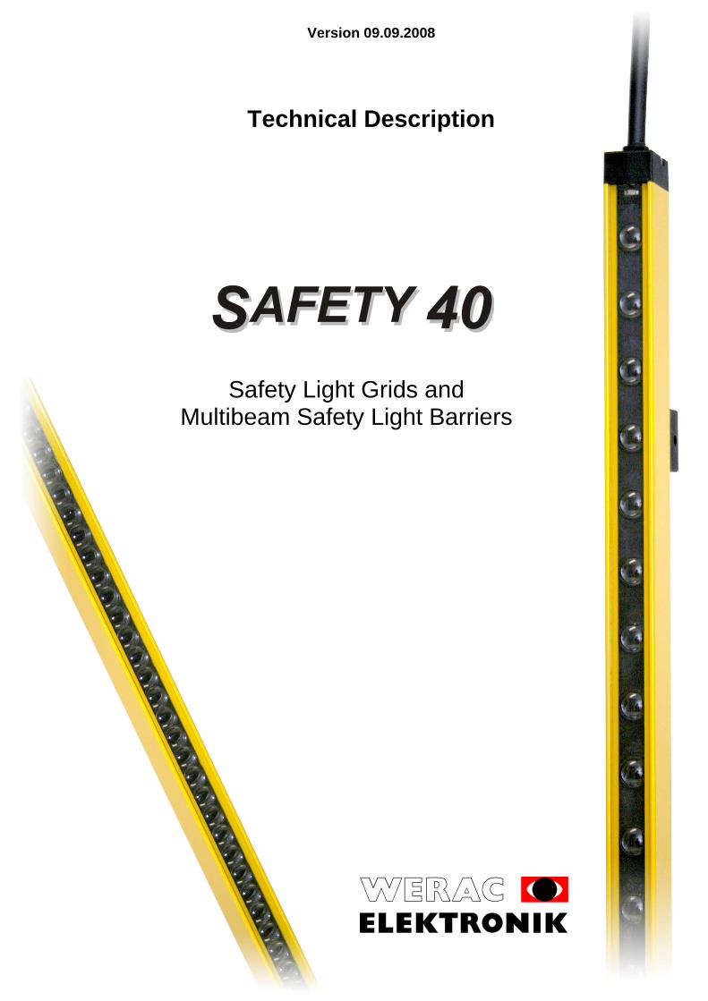
Safety Light Grids and
Multibeam Safety Light Barriers
Technical Description

Version 09.09.2008
page 2 WERAC Elektronik GmbH
1 General
This instruction manual is a constituent part of the SAFETY 40 safety light grid. It must be available to all personnel concerned with assembly, commissioning, and maintenance during its entire life cycle. If the instructions in this manual are not followed or only partly followed, accidents could occur. Any warranty claims against WERAC Elektronik GmbH become null and void in this case. Designated use: The safety systems SAFETY 40 consist of the certificated components control unit, transmitter and receiver (see type name) and may be used only coherently. The connections between the single components must be carried out with cables of the company WERAC. The system SAFETY 40 is a electro-sensitive protective equipment of the type 4 according to IEC 61496-1 which can be used depending on the implementation for the access security of danger zones and safeguarding dangerous points on power-driven machinery in compliance with the safety engineering requirements as stated in the standard EN 999/ ISO 13855 and the standards of the corresponding machinery up to category 4 according to EN 954-1/ ISO 13849-1.
1.1 Overview of the product features
• SAFETY 40 series for applications coming under Category 4 of EN 954-1/ ISO 13849-1 • Status display in the emitter (red, yellow, green) incl. alignment aid and contamination indicator • resolution 14 mm (finger guard), 30 mm (finger guard) or 40 mm (hand guard) • Width of guarded area with resolution 30 mm or 40 mm = 0 - 6 m or 3 – 10 m,
with 14 mm resolution = 0 - 6 m • Variable length in 50 mm steps up to 1900 mm – maximum 190 lines (with resolution 40 mm – 35 mm steps) • Small robust aluminium profile 29 x 19 mm for the emitter and receiver • Attachment optionally via the rail or on the end pieces • Cascadable: 2 light grids can be driven with one control unit • Switchgear with an identical interface to the machine controller as the control units of our multibeam safety light barriers • Can be also used as a multibeam light barrier e.g. as an access safeguard
1.2 Approval
EC type-test certificate: Fachausschuss Maschinenbau, Hebezeuge, Hütten- und Walzwerksanlagen [Expert Committee on Mechanical Engineering, Lifting Equipment, Iron-Making and Steel-Making. Testing and certification body of BG-PRÜFZERT, european notified body identification number 0393] Graf-Recke-Straße 69; D-40239 Düsseldorf
1.3 Manufacturer
WERAC Elektronik GmbH Telefone: +49 7271/6136 Am Rodaugraben 2 Telefax: +49 7271/8932 D-76744 Wörth am Rhein email: [email protected]
1.4 Version no.
This manual applies for the SAFETY 40 of version 1.15 of 25.05.07.
1.5 Approval marks
QM-System ISO 9001/2000
MHHW 06081

Version 09.09.2008
WERAC Elektronik GmbH page 3
2 Description of function
Our safety light grids consist of an emitter, a receiver and the WGN 100 control unit. The WGN 100 control unit must first of all be enabled via start enable T1, T2. This takes place through sequential switching (see e.g. 5.1) by pressing the start button. Provided that the light grid (LG) is not interrupted and without errors (the individual light beams are scanned in sequence), output relays A and B are activated. At least one contact of each relay (OSSD) is incorporated into the further processing of the sequential switching. The start and restart lockout must be carried out by the sequential switching as described under point 5. If one relay fails, the second one remains dropped, i.e. in a safe condition. The switching status of the relays is indicated in the control unit and visually indicated for the user in the emitter. The light grid is in the OFF state after power supply ON or a light barrier interruption. This is indicated by the red LED. Provided that the light grid has not been interrupted, the yellow LED is also lit. If the gain reserve of at least one light beam has significantly decreased compared to the last alignment, the yellow LED blinks (the light grid still functions). This is an indication for the user to clean the light grids (realignment may be necessary). The alignment is described under point 6.9. The current is supplied from the mains via a transformer with a PTC fuse.
3 Technical Data for the WGN 100-1 control unit
Standard to IEC EN 61496-1 Type 4 Response time see Chapter 6.4 Permissible operating temperature 0... +50°C / 32.. . +122°F Stock temperature -25°C... +70°C / -18°F... +158°F Supply voltage 24 V ± 10% 48 – 62 Hz Power consumption approx. 8 VA Output contacts: max. switching voltage max. switching current at 230 V~ (ind. load) max. switching frequency min. operating cycles
250 V~
2 A 2 /s
106 with contactor for 5.5 kW 3-phase motor Switch-on delay after power supply ON ~ 4 s Switch-on delay after test ON ≤ 70 ms Housing Sheet-metal housing with Makrolon cover Enclosure rating IP 20 Electrical connection Terminal plug, up to 2.5 mm²
RJ 45 connector (emitter and receiver) Status display red, yellow, green Start enable T1, T2 External voltage 10-50 V≅
Table 1

Version 09.09.2008
page 4 WERAC Elektronik GmbH
External connections control unit WGN 100 (see fig. 1) connection A1-A2 (normally open contact) security output relay A - OSSD 1 connection A5-A6 (normally open contact) security output relay B - OSSD 2 connection A3-A4 (normally closed contact) e.g., message to PLC, rest contact query,
display red connection A4-A7 (normally open contact) e.g., message to PLC, display green connection T1, T2 start release of the sequential switching connection 24V, 0V electricity supply with 24 V
Table 2 The relay outputs are line voltage isolated from the light barriers; to IEC60664 -1 overvoltage category III. All emitters WGS4... and WLS4... and all receivers WGE4... and WLE4... can be connected. The control unit is built only for the use inside of control cabinets. The Sheet-metal housing can be snapped on to the TS 35 for mounting inside control cabinets. The control cabinet must comply with degree of pollution 2 to IEC EN 60439-1 at least (This is normally IP 54). The mounting rail TS 35 must be connected to the PE conductor.
Technical Data for the emitters and receivers
WGS 4.../WGE 4... WLS 4.../WLE 4...
Standard to IEC EN 61496-1, -2 Type 4 Infrared pulsed light (950 nm) bundled on ± 2° Permissible operating temperature 0...+50 °C Stock temperature -25...+70 °C "Traffic light" display (see Table 4) red, yellow, green LED in the emitters Power supply ON indicator yellow LED in the receiver Housing Aluminium section tube 19 x 29 mm
Yellow (RAL 1021) powder-coated Enclosure IP 65, pane of polycarbonate
System length 50 mm to 2000 mm in 50 mm steps for 14 and 30 mm resolution
70 mm to 1995 mm in 35 mm steps for 40 mm resolution
Height of guarded area see Section 6.5 Resolution (WGS and WGE) 14, 30 or 40 mm Width of guarded area: resolution 14 mm res. 30 and 40 mm
0 - 6 m 0 - 6 m, 3 - 10 m with amplified emitters and
receivers Multibeam light barrier see Section 8.3 Electrical connection 165 mm round cable, 8 poles, screened
with connector M12 x 1 (socket connector) Cascadable (see 6.6) max. 2 light grids Maximum cable length from the control unit to emitter or receiver
10 m with UL-listed cables 15 m with VDE 0472/ 804-cables
Table 3
Version 09.09.2008
WERAC Elektronik GmbH page 5
4 Diagram of connections
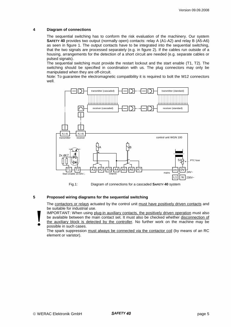
The sequential switching has to conform the risk evaluation of the machinery. Our system SAFETY 40 provides two output (normally open) contacts: relay A (A1-A2) and relay B (A5-A6) as seen in figure 1. The output contacts have to be integrated into the sequential switching, that the two signals are processed separately (e.g. in figure 2). If the cables run outside of a housing, arrangements for the detection of a short circuit are needed (e.g. separate cables or pulsed signals). The sequential switching must provide the restart lockout and the start enable (T1, T2). The switching should be specified in coordination with us. The plug connectors may only be manipulated when they are off-circuit. Note: To guarantee the electromagnetic compatibility it is required to bolt the M12 connectors well.
5 Proposed wiring diagrams for the sequential switc hing
The contactors or relays actuated by the control unit must have positively driven contacts and be suitable for industrial use. IMPORTANT: When using plug-in auxiliary contacts, the positively driven operation must also be available between the main contact set. It must also be checked whether disconnection of the auxiliary block is detected by the controller. No further work on the machine may be possible in such cases. The spark suppression must always be connected via the contactor coil (by means of an RC element or varistor).
Start enable 10-50V≅
0V
24V
L1 N or
mains
outputs
S1
24V~ 230V~
PTC fuse
2x 4K7
T1 T2 A2 A3 A4 A1
A B
A7 A5 A6
transmitter receiver
RJ 45
RJ 45
transmitter (cascaded)
receiver (cascaded)
receiver (standard)
transmitter (standard)
Fig.1: Diagram of connections for a cascaded SAFETY 40 system
control unit WGN 100
Version 09.09.2008
page 6 WERAC Elektronik GmbH
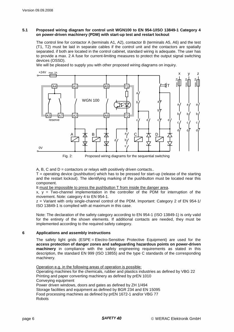
5.1 Proposed wiring diagram for control unit WGN100 to EN 954-1/ISO 13849-1 Category 4 on power-driven machinery (PDM) with start-up test and restart lockout
The control line for contactor A (terminals A1, A2), contactor B (terminals A5, A6) and the test (T1, T2) must be laid in separate cables if the control unit and the contactors are spatially separated. if both are located in the control cabinet, standard wiring is adequate. The user has to provide a max. 2 A fuse for current-limiting measures to protect the output signal switching devices (OSSD). We will be pleased to supply you with other proposed wiring diagrams on inquiry. A, B, C and D = contactors or relays with positively driven contacts.. T = operating device (pushbutton) which has to be pressed for start-up (release of the starting and the restart lockout). The identifying marking of the pushbutton must be located near this component. It must be impossible to press the pushbutton T from inside the danger area. x, y = Two-channel implementation in the controller of the PDM for interruption of the movement. Note: category 4 to EN 954-1. z = Variant with only single-channel control of the PDM. Important: Category 2 of EN 954-1/ ISO 13849-1 is complied with at maximum in this case. Note: The declaration of the safety category according to EN 954-1 (ISO 13849-1) is only valid for the entirety of the shown elements. If additional contacts are needed, they must be implemented according to the required safety category.
6 Applications and assembly instructions
The safety light grids (ESPE = Electro-Sensitive Protective Equipment) are used for the access protection of danger zones and safeguarding hazardous points on power-driven machinery in compliance with the safety engineering requirements as stated in this description, the standard EN 999 (ISO 13855) and the type C standards of the corresponding machinery. Operation e.g. in the following areas of operation is possible: Operating machines for the chemicals, rubber and plastics industries as defined by VBG 22 Printing and paper converting machinery as defined by prEN 1010 Conveying equipment Power driven windows, doors and gates as defined by ZH 1/494 Storage facilities and equipment as defined by BGR 234 and EN 15095 Food processing machines as defined by prEN 1672-1 and/or VBG 77 Robots
0V
+24V max. 2A
A1 T1
C B A D
d c
b
a
T
d c
b
a
A2 A6 T2
WGN 100
reserve
b
d
a
c
x
max
. 2A
b
d
a
c
z
max
. 2A
b
d
a
c
y
max
. 2A
d
c
b
a
A4
A3 A7
A5
Fig. 2: Proposed wiring diagrams for the sequential switching
Version 09.09.2008
WERAC Elektronik GmbH page 7
Textile machines as defined by VBG and DIN EN ISO 11 111 Packaging machines as defined by as defined by DIN EN 415-1 to -7 and/or VBG 76
The above individual applications were not an object of the EC type-test.
6.1 General remarks The operating device for start-up (pushbutton T) must be installed in such a way that a good overview of the danger area is provided from its operating position. Actuation of the operating device from inside the danger area must be excluded. The ESPE must be installed in such a way that the dangerous points can only be reached through the guarded area.
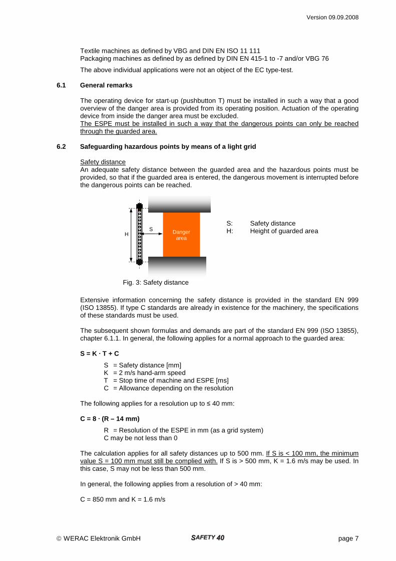
6.2 Safeguarding hazardous points by means of a lig ht grid Safety distance An adequate safety distance between the guarded area and the hazardous points must be provided, so that if the guarded area is entered, the dangerous movement is interrupted before the dangerous points can be reached. S: Safety distance H: Height of guarded area
Extensive information concerning the safety distance is provided in the standard EN 999 (ISO 13855). If type C standards are already in existence for the machinery, the specifications of these standards must be used. The subsequent shown formulas and demands are part of the standard EN 999 (ISO 13855), chapter 6.1.1. In general, the following applies for a normal approach to the guarded area: S = K · T + C
S = Safety distance [mm] K = 2 m/s hand-arm speed T = Stop time of machine and ESPE [ms] C = Allowance depending on the resolution The following applies for a resolution up to ≤ 40 mm: C = 8 · (R – 14 mm)
R = Resolution of the ESPE in mm (as a grid system) C may be not less than 0 The calculation applies for all safety distances up to 500 mm. If S is < 100 mm, the minimum value S = 100 mm must still be complied with. If S is > 500 mm, K = 1.6 m/s may be used. In this case, S may not be less than 500 mm. In general, the following applies from a resolution of > 40 mm: C = 850 mm and K = 1.6 m/s
Danger area
S H
Fig. 3: Safety distance
Version 09.09.2008
page 8 WERAC Elektronik GmbH
If children are present (non industrial area), the safety distance S must be increased by at least 75 mm. Example: A machine with a braking time of 100 ms is equipped with a light grid (ESPE) with a resolution of 30 mm and a response time of 20 ms. C = 8 · (30 – 14 mm) = 128 mm S = 2 m/s · (100 ms +20 ms) + 128 mm = 240 mm + 128 mm = 368 m m If a resolution of 14 mm is used in an otherwise identical machine, a safety distance S = 2 m/s (100 ms +20 ms) + 0 mm = 240 mm results. If the ESPE is used as finger, hand or arm protection, it must be mounted in such a way that the guarded area cannot be reached over, reached under, reached around or stepped behind. If this requirement cannot be met solely by the ESPE, additional protective devices such as fixed covers must be provided. Information in the operating manual of the machine ● Maximum machine stopping time ● Safety distance S ● Guarded area dimensions (height × max. width of guarded area of the light barriers) ● Test rod diameter ● Reaction time T (stop time of machine and ESPE)
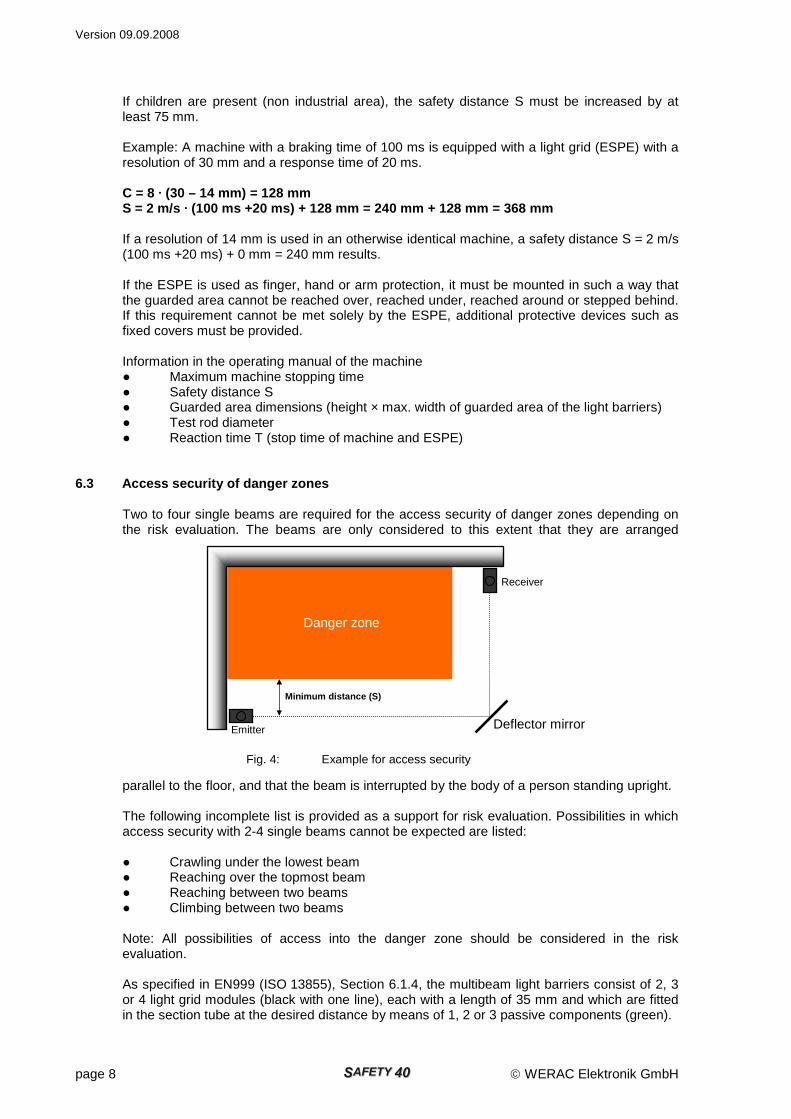
6.3 Access security of danger zones Two to four single beams are required for the access security of danger zones depending on the risk evaluation. The beams are only considered to this extent that they are arranged
parallel to the floor, and that the beam is interrupted by the body of a person standing upright. The following incomplete list is provided as a support for risk evaluation. Possibilities in which access security with 2-4 single beams cannot be expected are listed: ● Crawling under the lowest beam ● Reaching over the topmost beam ● Reaching between two beams ● Climbing between two beams Note: All possibilities of access into the danger zone should be considered in the risk evaluation. As specified in EN999 (ISO 13855), Section 6.1.4, the multibeam light barriers consist of 2, 3 or 4 light grid modules (black with one line), each with a length of 35 mm and which are fitted in the section tube at the desired distance by means of 1, 2 or 3 passive components (green).
Minimum distance (S)
Receiver
Deflector mirror Emitter
Danger zone
Fig. 4: Example for access security
Version 09.09.2008
WERAC Elektronik GmbH page 9
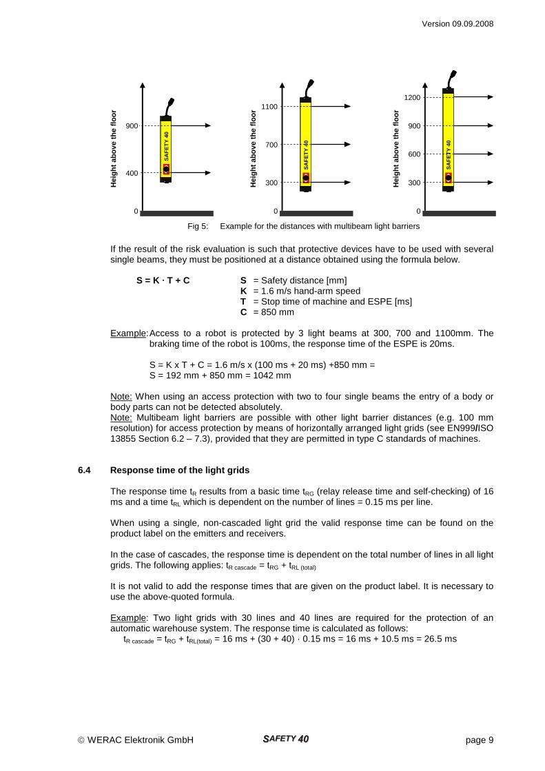
If the result of the risk evaluation is such that protective devices have to be used with several single beams, they must be positioned at a distance obtained using the formula below. S = K · T + C S = Safety distance [mm] K = 1.6 m/s hand-arm speed T = Stop time of machine and ESPE [ms] C = 850 mm Example: Access to a robot is protected by 3 light beams at 300, 700 and 1100mm. The
braking time of the robot is 100ms, the response time of the ESPE is 20ms. S = K x T + C = 1.6 m/s x (100 ms + 20 ms) +850 mm = S = 192 mm + 850 mm = 1042 mm Note: When using an access protection with two to four single beams the entry of a body or body parts can not be detected absolutely. Note: Multibeam light barriers are possible with other light barrier distances (e.g. 100 mm resolution) for access protection by means of horizontally arranged light grids (see EN999/ISO 13855 Section 6.2 – 7.3), provided that they are permitted in type C standards of machines.
6.4 Response time of the light grids The response time tR results from a basic time tRG (relay release time and self-checking) of 16 ms and a time tRL which is dependent on the number of lines = 0.15 ms per line. When using a single, non-cascaded light grid the valid response time can be found on the product label on the emitters and receivers. In the case of cascades, the response time is dependent on the total number of lines in all light grids. The following applies: tR cascade = tRG + tRL (total) It is not valid to add the response times that are given on the product label. It is necessary to use the above-quoted formula. Example: Two light grids with 30 lines and 40 lines are required for the protection of an automatic warehouse system. The response time is calculated as follows:
tR cascade = tRG + tRL(total) = 16 ms + (30 + 40) · 0.15 ms = 16 ms + 10.5 ms = 26.5 ms
SA
FE
TY
40
1100
700
300
0
Hei
ght a
bove
the
floor
Fig 5: Example for the distances with multibeam light barriers
SA
FE
TY
40
900
400
0
Hei
ght a
bove
the
floor
SA
FE
TY
40
900
600
300
0
Hei
ght a
bove
the
floor
1200
Version 09.09.2008
page 10 WERAC Elektronik GmbH
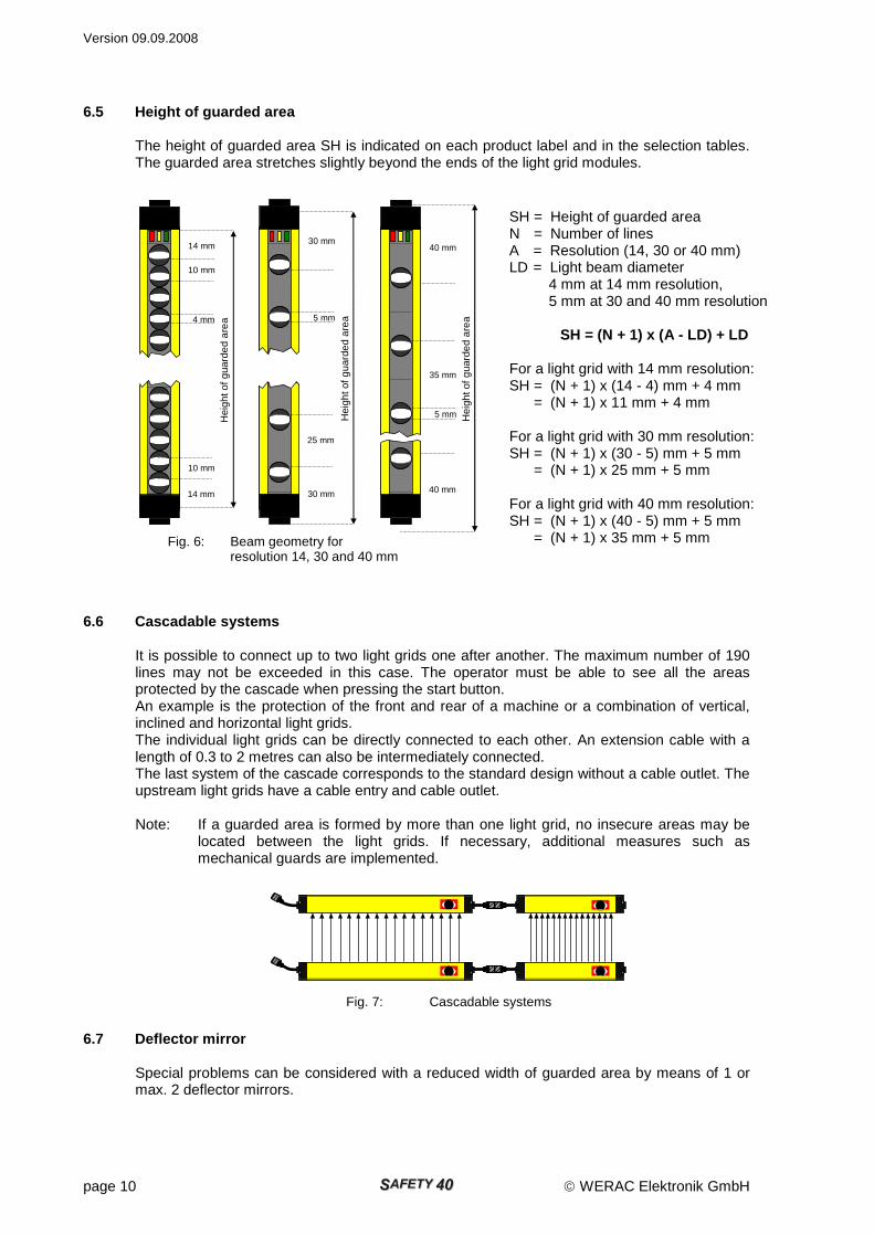
6.5 Height of guarded area The height of guarded area SH is indicated on each product label and in the selection tables. The guarded area stretches slightly beyond the ends of the light grid modules.
6.6 Cascadable systems It is possible to connect up to two light grids one after another. The maximum number of 190 lines may not be exceeded in this case. The operator must be able to see all the areas protected by the cascade when pressing the start button. An example is the protection of the front and rear of a machine or a combination of vertical, inclined and horizontal light grids. The individual light grids can be directly connected to each other. An extension cable with a length of 0.3 to 2 metres can also be intermediately connected. The last system of the cascade corresponds to the standard design without a cable outlet. The upstream light grids have a cable entry and cable outlet. Note: If a guarded area is formed by more than one light grid, no insecure areas may be
located between the light grids. If necessary, additional measures such as mechanical guards are implemented.
6.7 Deflector mirror Special problems can be considered with a reduced width of guarded area by means of 1 or max. 2 deflector mirrors.
Fig. 7: Cascadable systems
SH = Height of guarded area N = Number of lines A = Resolution (14, 30 or 40 mm) LD = Light beam diameter 4 mm at 14 mm resolution, 5 mm at 30 and 40 mm resolution
SH = (N + 1) x (A - LD) + LD For a light grid with 14 mm resolution: SH = (N + 1) x (14 - 4) mm + 4 mm = (N + 1) x 11 mm + 4 mm For a light grid with 30 mm resolution: SH = (N + 1) x (30 - 5) mm + 5 mm = (N + 1) x 25 mm + 5 mm For a light grid with 40 mm resolution: SH = (N + 1) x (40 - 5) mm + 5 mm = (N + 1) x 35 mm + 5 mm Fig. 6: Beam geometry for
resolution 14, 30 and 40 mm
Hei
ght o
f gua
rded
are
a
30 mm
5 mm
25 mm
30 mm
Hei
ght o
f gua
rded
are
a
14 mm
4 mm
10 mm
14 mm
10 mm
40 mm
40 mm
Hei
ght o
f gua
rded
are
a
35 mm
5 mm
Version 09.09.2008
WERAC Elektronik GmbH page 11
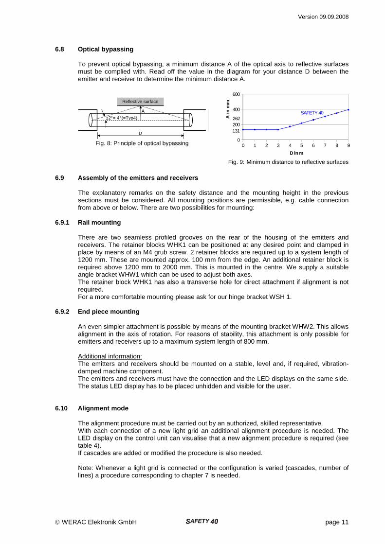
6.8 Optical bypassing To prevent optical bypassing, a minimum distance A of the optical axis to reflective surfaces must be complied with. Read off the value in the diagram for your distance D between the emitter and receiver to determine the minimum distance A.
6.9 Assembly of the emitters and receivers
The explanatory remarks on the safety distance and the mounting height in the previous sections must be considered. All mounting positions are permissible, e.g. cable connection from above or below. There are two possibilities for mounting:
6.9.1 Rail mounting There are two seamless profiled grooves on the rear of the housing of the emitters and receivers. The retainer blocks WHK1 can be positioned at any desired point and clamped in place by means of an M4 grub screw. 2 retainer blocks are required up to a system length of 1200 mm. These are mounted approx. 100 mm from the edge. An additional retainer block is required above 1200 mm to 2000 mm. This is mounted in the centre. We supply a suitable angle bracket WHW1 which can be used to adjust both axes. The retainer block WHK1 has also a transverse hole for direct attachment if alignment is not required. For a more comfortable mounting please ask for our hinge bracket WSH 1.
6.9.2 End piece mounting An even simpler attachment is possible by means of the mounting bracket WHW2. This allows alignment in the axis of rotation. For reasons of stability, this attachment is only possible for emitters and receivers up to a maximum system length of 800 mm. Additional information: The emitters and receivers should be mounted on a stable, level and, if required, vibration-damped machine component. The emitters and receivers must have the connection and the LED displays on the same side. The status LED display has to be placed unhidden and visible for the user.
6.10 Alignment mode The alignment procedure must be carried out by an authorized, skilled representative. With each connection of a new light grid an additional alignment procedure is needed. The LED display on the control unit can visualise that a new alignment procedure is required (see table 4). If cascades are added or modified the procedure is also needed.
Note: Whenever a light grid is connected or the configuration is varied (cascades, number of lines) a procedure corresponding to chapter 7 is needed.
Reflective surface
D
A
±2° = 4° (=Typ4)
Fig. 8: Principle of optical bypassing
262
0
200
400
600
0 1 2 3 4 5 6 7 8 9
D in m
A in
mm
SAFETY 40
131
Fig. 9: Minimum distance to reflective surfaces
Version 09.09.2008
page 12 WERAC Elektronik GmbH
6.10.1 Alignment of the emitters and receivers The procedure for alignment of the emitter and receiver elements is described in the following section: • The emitters and receivers are mounted as described under 6.9. Ensure that the
longitudinal axes are aligned in parallel during the assembly. Use a spirit level for this purpose. Care should also be taken that the axis of rotation is set as accurately as possible.
• Set DIP S1-1 in the control unit WGN 100 to ON (alignment mode). Switch on power supply.
• Next determine the reception range of the receiver by rotating it around the longitudinal axis. The yellow LED in the "traffic light" shines, when there is a sufficient light reserve on all lines of the grid. The red LED is lit as soon as one single line is not receiving any light. If none of the both LED is shining there is not enough light for operation of the light grid.
• Place the receiver in the centre of the reception range and secure. • Follow the same procedure to adjust and attach the emitters. • Switch off DIP S1-1. The control unit will now store the amplification reference values of the
individual lines after a waiting period of 5-7 seconds (intermission indicated by flickering red LED to get the hand out of the guarded area). Once this procedure has been completed, the red LED starts to blink. Switch off the power supply to exit the alignment mode. After reconnection, the light grid enters the stand-by mode (red and yellow LEDs are lit). It switches to green (OSSD = ON) as soon as the start button is pressed and the light grid is not interrupted.
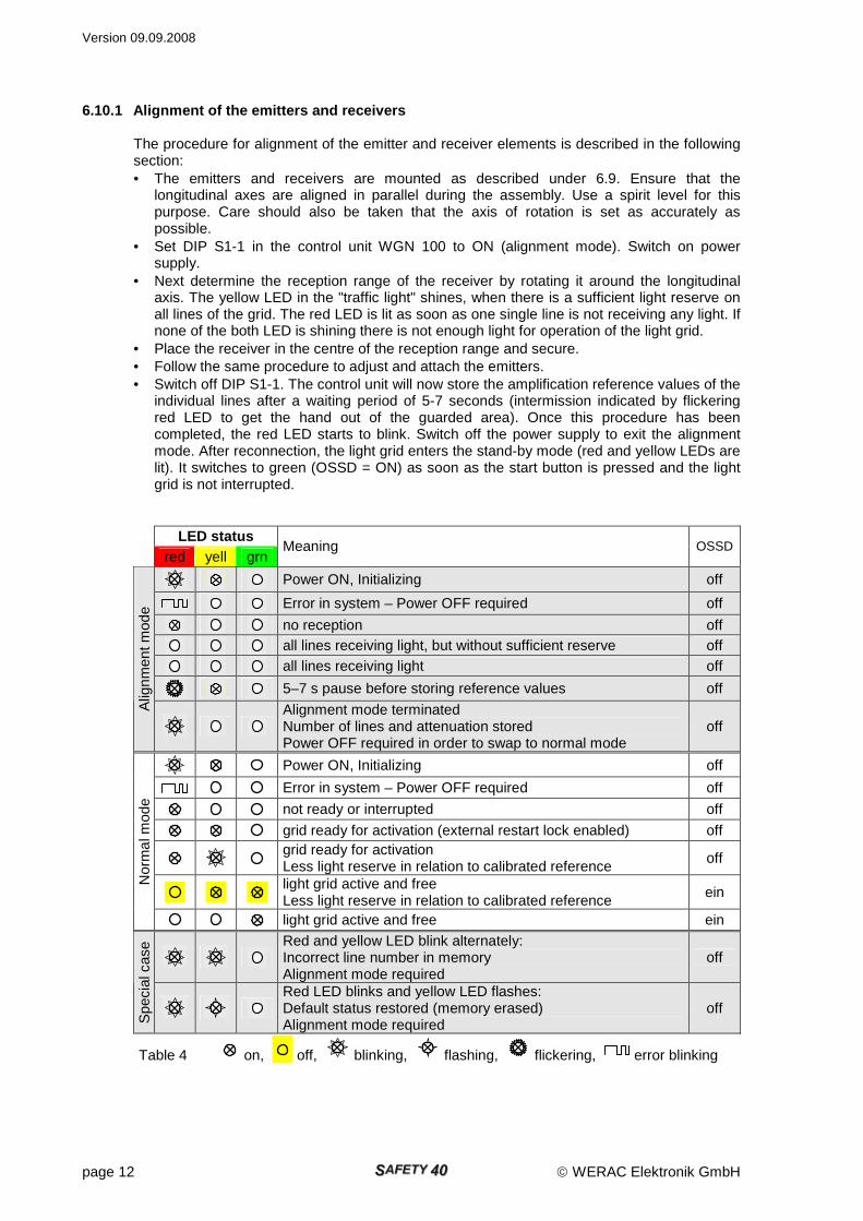
LED status red yell grn
Meaning OSSD
Power ON, Initializing off
Error in system – Power OFF required off
no reception off
all lines receiving light, but without sufficient reserve off
all lines receiving light off
5–7 s pause before storing reference values off
Alig
nmen
t mod
e
Alignment mode terminated Number of lines and attenuation stored Power OFF required in order to swap to normal mode
off
Power ON, Initializing off
Error in system – Power OFF required off
not ready or interrupted off
grid ready for activation (external restart lock enabled) off
grid ready for activation Less light reserve in relation to calibrated reference
off
light grid active and free Less light reserve in relation to calibrated reference
ein
Nor
mal
mod
e
light grid active and free ein
Red and yellow LED blink alternately: Incorrect line number in memory Alignment mode required
off
Spe
cial
cas
e
Red LED blinks and yellow LED flashes: Default status restored (memory erased) Alignment mode required
off
Table 4 on, off, blinking, flashing, flickering, error blinking

Version 09.09.2008
WERAC Elektronik GmbH page 13
Assignment of DIP-switch S1: ON OFF S1-1: Alignment mode Normal operation S1-2: unassigned unassigned S1-3: unassigned unassigned S1-4: unassigned unassigned Table 5
Note: During the alignment mode the OSSDs are switched OFF.
6.10.2 Alignment of cascades First of all, the light grid directly connected to the control unit is adjusted as described under 6.9. In this regard, the output cables to the next light grid must be separated and terminated with the termination plug WAC1. The second light grid can now be connected and adjusted. It is possible to connect two light grids in cascade in this way.
7 Commissioning and regular inspections
The commissioning engineer must have all the requisite information on the machine and the mounted ESPE available. An inspection must be carried out by a qualified person before the initial start-up of ESPE (The manufacturer of the press is also to be included for presses). The inspection must extend to the perfect interaction of the ESPE with the controller of the power-driven machinery and the setup in compliance with these safety regulations (see also EN 999/ ISO 13855 and the type C standards of the corresponding machinery). The inspection results must be documented in a report, which must be signed by the inspector. The report must be kept at the site of installation of the power-driven machinery. The user must have a safety inspection carried out by a qualified person (for finger/hand/arm protection) or an authorised representative (access security) every 6 or 12 months. This also includes a check as to whether the after-running of the machine is in the permissible range. Records of these inspections also must be prepared and kept.
Version 09.09.2008
page 14 WERAC Elektronik GmbH
The following must be verified after any retooling or repair: 1. The ESPE required for safety is operative (testing the guarded area with the test rod) 2. The dangerous point can only be reached through the guarded area 3. The dangerous process can only be executed if there is nobody between the guarded area
and the dangerous point 4. The specified safety distance between the guarded area and
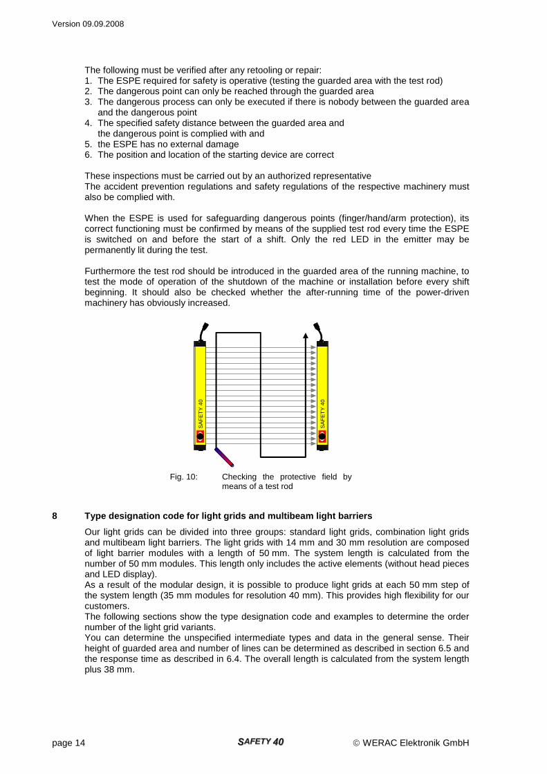
the dangerous point is complied with and 5. the ESPE has no external damage 6. The position and location of the starting device are correct These inspections must be carried out by an authorized representative The accident prevention regulations and safety regulations of the respective machinery must also be complied with. When the ESPE is used for safeguarding dangerous points (finger/hand/arm protection), its correct functioning must be confirmed by means of the supplied test rod every time the ESPE is switched on and before the start of a shift. Only the red LED in the emitter may be permanently lit during the test. Furthermore the test rod should be introduced in the guarded area of the running machine, to test the mode of operation of the shutdown of the machine or installation before every shift beginning. It should also be checked whether the after-running time of the power-driven machinery has obviously increased.
8 Type designation code for light grids and multibe am light barriers
Our light grids can be divided into three groups: standard light grids, combination light grids and multibeam light barriers. The light grids with 14 mm and 30 mm resolution are composed of light barrier modules with a length of 50 mm. The system length is calculated from the number of 50 mm modules. This length only includes the active elements (without head pieces and LED display). As a result of the modular design, it is possible to produce light grids at each 50 mm step of the system length (35 mm modules for resolution 40 mm). This provides high flexibility for our customers. The following sections show the type designation code and examples to determine the order number of the light grid variants. You can determine the unspecified intermediate types and data in the general sense. Their height of guarded area and number of lines can be determined as described in section 6.5 and the response time as described in 6.4. The overall length is calculated from the system length plus 38 mm.
Fig. 10: Checking the protective field by means of a test rod
SA
FE
TY
40
SA
FE
TY
40
Version 09.09.2008
WERAC Elektronik GmbH page 15
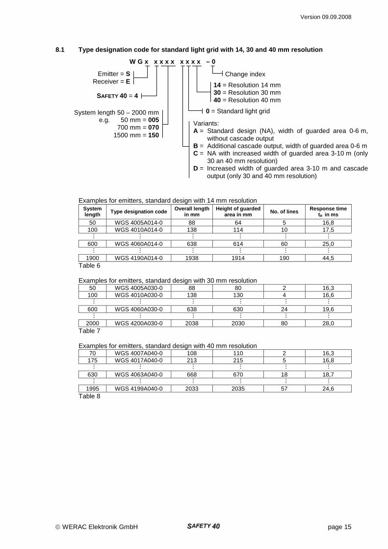
8.1 Type designation code for standard light grid w ith 14, 30 and 40 mm resolution
W G x x x x x x x x x – 0
Examples for emitters, standard design with 14 mm resolution System length Type designation code Overall length
in mm Height of guarded
area in mm No. of lines Response time tR in ms
50 WGS 4005A014-0 88 64 5 16,8 100 WGS 4010A014-0 138 114 10 17,5
600 WGS 4060A014-0 638 614 60 25,0
1900 WGS 4190A014-0 1938 1914 190 44,5
Table 6 Examples for emitters, standard design with 30 mm resolution
50 WGS 4005A030-0 88 80 2 16,3 100 WGS 4010A030-0 138 130 4 16,6
600 WGS 4060A030-0 638 630 24 19,6
2000 WGS 4200A030-0 2038 2030 80 28,0
Table 7 Examples for emitters, standard design with 40 mm resolution
70 WGS 4007A040-0 108 110 2 16,3 175 WGS 4017A040-0 213 215 5 16,8
630 WGS 4063A040-0 668 670 18 18,7
1995 WGS 4199A040-0 2033 2035 57 24,6
Table 8
14 = Resolution 14 mm 30 = Resolution 30 mm 40 = Resolution 40 mm
Emitter = S Receiver = E
SAFETY 40 = 4
0 = Standard light grid System length 50 – 2000 mm e.g. 50 mm = 005
700 mm = 070 1500 mm = 150
Variants: A = Standard design (NA), width of guarded area 0-6 m,
without cascade output B = Additional cascade output, width of guarded area 0-6 m C = NA with increased width of guarded area 3-10 m (only
30 an 40 mm resolution) D = Increased width of guarded area 3-10 m and cascade
output (only 30 and 40 mm resolution)
Change index
...
...
...
...
...
...
...
...
...
...
...
...
...
...
...
...
...
...
...
...
...
...
...
...
...
...
...
...
...
...
...
...
...
...
...
...
Version 09.09.2008
page 16 WERAC Elektronik GmbH
8.2 Combination light grid with 14/30 mm or 14/40 m m resolution
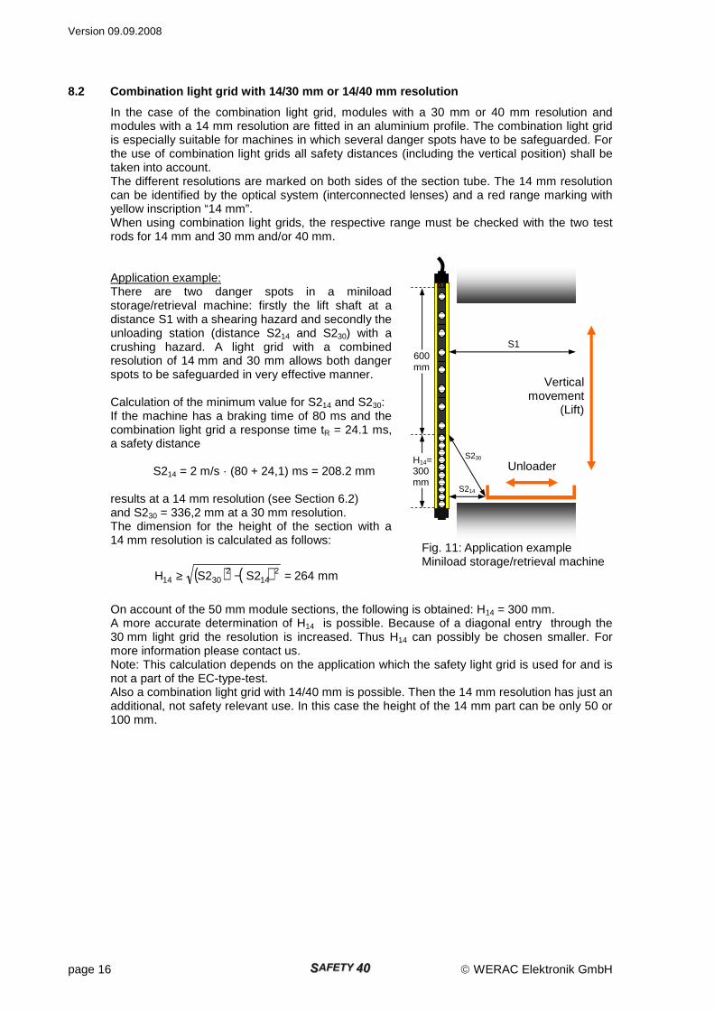
In the case of the combination light grid, modules with a 30 mm or 40 mm resolution and modules with a 14 mm resolution are fitted in an aluminium profile. The combination light grid is especially suitable for machines in which several danger spots have to be safeguarded. For the use of combination light grids all safety distances (including the vertical position) shall be taken into account. The different resolutions are marked on both sides of the section tube. The 14 mm resolution can be identified by the optical system (interconnected lenses) and a red range marking with yellow inscription “14 mm”. When using combination light grids, the respective range must be checked with the two test rods for 14 mm and 30 mm and/or 40 mm. Application example: There are two danger spots in a miniload storage/retrieval machine: firstly the lift shaft at a distance S1 with a shearing hazard and secondly the unloading station (distance S214 and S230) with a crushing hazard. A light grid with a combined resolution of 14 mm and 30 mm allows both danger spots to be safeguarded in very effective manner. Calculation of the minimum value for S214 and S230: If the machine has a braking time of 80 ms and the combination light grid a response time tR = 24.1 ms, a safety distance
S214 = 2 m/s · (80 + 24,1) ms = 208.2 mm
results at a 14 mm resolution (see Section 6.2) and S230 = 336,2 mm at a 30 mm resolution. The dimension for the height of the section with a 14 mm resolution is calculated as follows:
( ) ( ) mm2642S2SH 214
23014 =−≥
On account of the 50 mm module sections, the following is obtained: H14 = 300 mm. A more accurate determination of H14 is possible. Because of a diagonal entry through the 30 mm light grid the resolution is increased. Thus H14 can possibly be chosen smaller. For more information please contact us. Note: This calculation depends on the application which the safety light grid is used for and is not a part of the EC-type-test. Also a combination light grid with 14/40 mm is possible. Then the 14 mm resolution has just an additional, not safety relevant use. In this case the height of the 14 mm part can be only 50 or 100 mm.
Fig. 11: Application example Miniload storage/retrieval machine
600 mm
H14=300 mm
S214
Unloader
Vertical movement
(Lift)
S1
S230
Version 09.09.2008
WERAC Elektronik GmbH page 17
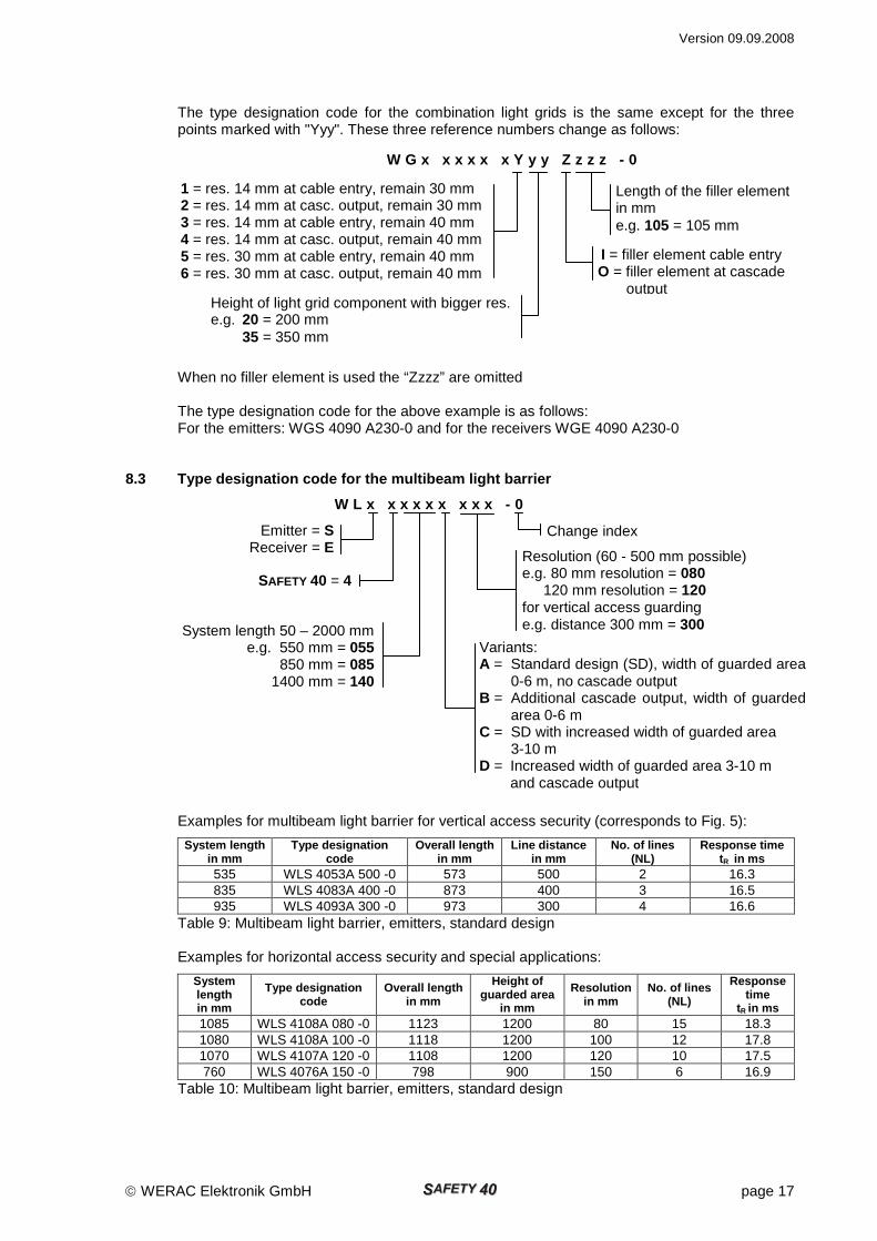
The type designation code for the combination light grids is the same except for the three points marked with "Yyy". These three reference numbers change as follows:
W G x x x x x x Y y y Z z z z - 0
When no filler element is used the “Zzzz” are omitted The type designation code for the above example is as follows: For the emitters: WGS 4090 A230-0 and for the receivers WGE 4090 A230-0
8.3 Type designation code for the multibeam light b arrier
W L x x x x x x x x x - 0
Examples for multibeam light barrier for vertical access security (corresponds to Fig. 5):
System length in mm
Type designation code
Overall length in mm
Line distance in mm
No. of lines (NL)
Response time tR in ms
535 WLS 4053A 500 -0 573 500 2 16.3 835 WLS 4083A 400 -0 873 400 3 16.5 935 WLS 4093A 300 -0 973 300 4 16.6
Table 9: Multibeam light barrier, emitters, standard design Examples for horizontal access security and special applications:
System length in mm
Type designation code
Overall length in mm
Height of guarded area
in mm
Resolution in mm
No. of lines (NL)
Response time
tR in ms 1085 WLS 4108A 080 -0 1123 1200 80 15 18.3 1080 WLS 4108A 100 -0 1118 1200 100 12 17.8 1070 WLS 4107A 120 -0 1108 1200 120 10 17.5 760 WLS 4076A 150 -0 798 900 150 6 16.9
Table 10: Multibeam light barrier, emitters, standard design
System length 50 – 2000 mm e.g. 550 mm = 055
850 mm = 085 1400 mm = 140
Resolution (60 - 500 mm possible) e.g. 80 mm resolution = 080 120 mm resolution = 120 for vertical access guarding e.g. distance 300 mm = 300
Emitter = S Receiver = E
SAFETY 40 = 4
Variants: A = Standard design (SD), width of guarded area
0-6 m, no cascade output B = Additional cascade output, width of guarded area 0-6 m C = SD with increased width of guarded area 3-10 m D = Increased width of guarded area 3-10 m and cascade output
Change index
1 = res. 14 mm at cable entry, remain 30 mm 2 = res. 14 mm at casc. output, remain 30 mm 3 = res. 14 mm at cable entry, remain 40 mm 4 = res. 14 mm at casc. output, remain 40 mm 5 = res. 30 mm at cable entry, remain 40 mm 6 = res. 30 mm at casc. output, remain 40 mm
Height of light grid component with bigger res. e.g. 20 = 200 mm 35 = 350 mm
Length of the filler element in mm e.g. 105 = 105 mm
I = filler element cable entry O = filler element at cascade output

Version 09.09.2008
page 18 WERAC Elektronik GmbH
Other system lengths (SL) can be determined as follows:
SL = NL · 35 mm + (NL – 1) · (Resolution – 40 mm)
Example 1: Resolution = 100 mm; number of lines = 12 SL = 12 · 35 mm + 11 · 60 = 420 + 660 = 1080 mm
Example 2: Resolution = 80 mm; number of lines = 15 SL = 15 · 35 mm + 14 · 40 = 525 + 560 = 1085 mm Other line distances and resolutions are possible. Please contact us.
8.4 Type designation code for the control unit
WGN 100 -1
8.5 Ordering instructions
Please state the following when ordering: • Emitter type • Receiver type • Control unit type for power supply 24 VAC • Cable (control unit to emitter and receiver) with 8 pole screened cable, connector M12x1
(to emitter and receiver) and RJ45 (to control unit) Cable length optionally 2 m, 3 m, 5 m, 7 m, 10 m, (15 m without UL-listing)
• A connecting cable may be required for cascades. Cable 8 pole screened with M12x1 connector and socket, length optionally 0.3 m, 1 m, 2 m. (with UL-listing)
• Depending on the mounting type: for rail mounting: number of retainer blocks WHK1
number of angle brackets WHW1 or number of hinge brackets WSH1
for end piece mounting: number of mounting brackets WHW2
Supplied accessories (free of charge): 1 ea. technical description in German or English or French 1 ea. WERAC test rod 14 mm (WGP14), 30 mm (WGP30) or 40 mm (WGP40) (Two test rods for combination light grids) For cascades 2 ea. termination plug (WAC1)
9 Product labels for emitters and receivers
All the relevant information can be found on the product label, which is attached to the emitter and the receiver. Fig. 12 shows e.g. the product label of an emitter.
Change index WERAC Control unit
Type number
Fig. 12
Version 09.09.2008
WERAC Elektronik GmbH page 19
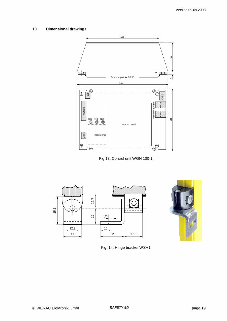
10 Dimensional drawings
Fig 13: Control unit WGN 100-1
Fig. 14: Hinge bracket WSH1
168
DIP
S1
115
7 Snap-on part for TS 35
52
135
RJ
45
Rec
eive
r E
mitt
er
RJ
45
Tes
t
Out
puts
M
ains
Transformer
grn yell red
Product label
10
22
15 25
,8
13,3
17,5 17
12,2
5,2
Version 09.09.2008
page 20 WERAC Elektronik GmbH
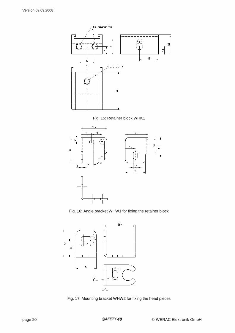
Fig. 15: Retainer block WHK1
Fig. 16: Angle bracket WHW1 for fixing the retainer block
Fig. 17: Mounting bracket WHW2 for fixing the head pieces
Brass socket M4
Brass socket M4x8
Version 09.09.2008
WERAC Elektronik GmbH page 21
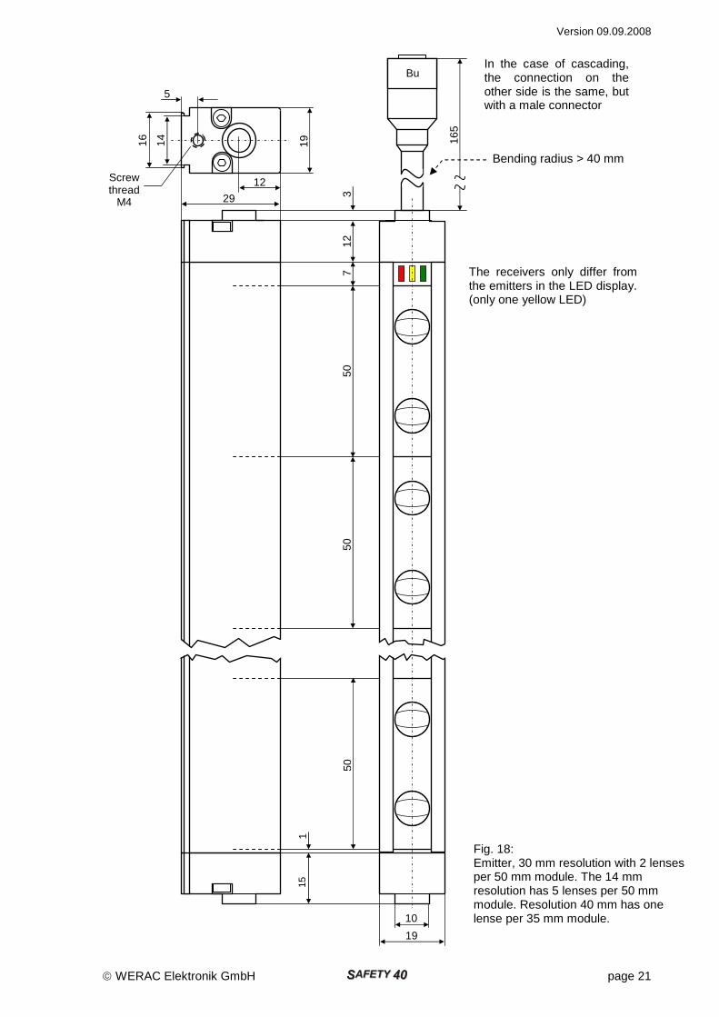
The receivers only differ from the emitters in the LED display. (only one yellow LED)
Fig. 18: Emitter, 30 mm resolution with 2 lenses per 50 mm module. The 14 mm resolution has 5 lenses per 50 mm module. Resolution 40 mm has one lense per 35 mm module.
In the case of cascading, the connection on the other side is the same, but with a male connector
Bending radius > 40 mm
50
50
7 12
3
19
14
16
5
12
15
1
50
10
19
Bu
165
29
Screw thread
M4