Embed Size (px)
Citation preview

511 McCormick Blvd. London, ON Canada N5W 4C8
General Info/Tech Support: 1 855. 247 4200
Online: www.lifebreath.com
RNC SERIES INSTALLATION GUIDE
69-RNC-INSTALL 0620

TABLE OF CONTENTS
LOCATION ........................................................................................................... 2
PRE-INSTALLATION NOTES .................................................................................. 3
SIMPLIFIED INSTALLATION (RETURN/RETURN METHOD) ......................................... 4
PARTIALLY DEDICATED SYSTEM ........................................................................... 5
FULLY DEDICATED SYSTEM, ................................................................................ 6
HANGING STRAP INSTRUCTIONS .......................................................................... 7
MOUNTING INSTRUCTIONS FOR RNC4 MODELS .................................................... 8
DRAIN CONNECTION ............................................................................................ 9
DRAIN CONNECTION FOR RNC4 MODELS ............................................................. 10
GRILLES ............................................................................................................. 11
GRILLE FITTINGS ................................................................................................. 12
LIFEBREATH WEATHERHOOD AND WEATHER HOOD REQUIREMENTS ...................... 13
DUAL HOOD ........................................................................................................ 14
MAIN CONTROL INSTALLATION ............................................................................. 15
MECHANICAL TIMERS INSTALLATION ..................................................................... 16
INSTALLATION AND OPERATION OF 20/40/60 MINUTE TIMER: DET02 .................... 17
INSTALLATION AND PAIRING OF REPEATERS: 99-RX02 ......................................... 18
INSTALLER SELECTABLE HIGH-SPEED SETTINGS .................................................. 18
INSTALLATION AND OPERATION OF 20/40/60 MINUTE TIMER: DET01 ..................... 19
DIMENSIONAL MODEL DRAWINGS – RNC4-TPD/TPF ........................................... 20
DIMENSIONAL MODEL DRAWINGS – RNC5-HEX-TPD/TPF .................................. 21
DIMENSIONAL MODEL DRAWINGS – RNC5-TPD/TPF/RNC6-ES.......................... 22
DIMENSIONAL MODEL DRAWINGS – RNC95 AND RNC 155 ................................... 22
DIMENSIONAL MODEL DRAWINGS – RNC200 AND RNC205.................................. 23
BALANCING THE AIRFLOWS .................................................................................. 24
DETERMINING THE CFM ...................................................................................... 25
BALANCING COLLAR INSTRUCTIONS .................................................................... 26
BALANCING THE AIRFLOW USING DOOR PORTS ...................................................... 27
BALANCING DOOR PORT ILLUSTRATIONS ............................................................... 28
AIRFLOW REFERENCE CHART- RNC4-TPD .......................................................... 29
AIRFLOW REFERENCE CHART- RNC4-TPF .......................................................... 30
AIRFLOW REFERENCE CHART- RNC5-TPD/TPF .................................................. 31/32
AIRFLOW REFERENCE CHART- RNC6-ES ............................................................ 33/34
AIRFLOW REFERENCE CHART- RNC5-HEX-TPD/TPF ......................................... 35/36
AIRFLOW REFERENCE CHART- RNC155 .............................................................. 37/38
AIRFLOW REFERENCE CHART- RNC205 .............................................................. 39/40
AIRFLOW REFERENCE CHART- RNC200 .............................................................. 41
TROUBLESHOOTING ............................................................................................. 42
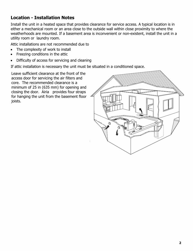
Location - Installation Notes Install the unit in a heated space that provides clearance for service access. A typical location is in either a mechanical room or an area close to the outside wall within close proximity to where the weatherhoods are mounted. If a basement area is inconvenient or non-existent, install the unit in a utility room or laundry room.
Attic installations are not recommended due to The complexity of work to install Freezing conditions in the attic
Difficulty of access for servicing and cleaning
If attic installation is necessary the unit must be situated in a conditioned space.
Leave sufficient clearance at the front of the access door for servicing the air filters and core. The recommended clearance is a minimum of 25 in (635 mm) for opening and closing the door. Airia provides four straps for hanging the unit from the basement floor joists.
2
Pre-Installation Notes
Read this notice before installing unit:
Disconnect the power from the unit before cleaning or servicing
To prevent electrical shock, it is extremely important to confirm the polarity of the power line that is switched by thesafety (disconnect) switch. The hot line (black) is the proper line for switching. Use either a voltmeter or test lampto confirm the absence of a voltage between the disconnect switch and ground (on the cabinet) while the door isopen. This procedure must be followed, as dwellings are occasionally wired improperly. Always ensure the propergrounding of the unit.
Improper installation, adjustment, alteration, service or maintenance can cause property damage, personal injury orloss of life. Installation and service must be performed by a qualified installer or service agency.
Warning
Do not apply electrical power to the unit until after the completion of the installation (including installation of lowvoltage control wiring).
Ensure the installation and wiring is in accordance with CEC, NEC, and local electrical codes.
Plug the unit into a standard designated (120 VAC) electrical outlet with ground.
The use of an extension cord with this unit is not recommended. If the installation requires further wiring, have alicensed electrician make all of the electrical connections. The recommended circuit is a separate 15 A/120 V circuit.
Attention
Before installation, careful consideration must be given to how this system will operate if connected to any otherpiece of mechanical equipment, i.e. a forced air furnace or air handler, operating at a higher static. Afterinstallation, the compatibility of the two pieces of equipment must be confirmed, by measuring the airflows of theHRV, by using the balancing procedure found in this manual. Never install a ventilator in a situation where itsnormal operation, lack of operation or partial failure may result in the backdrafting or improper functioning ofvented combustion equipment.
Unit must be installed level to ensure proper condensate drainage. Due to the broad range of installation andoperational conditions, consider the possibility of condensation forming on either the unit or connecting ducting.Objects below the installation may be exposed to condensate.
Do not install control wiring alongside electrical wire.
Caution
Due to ongoing research and product development, specifications, ratings, and dimensions are subject to changewithout notice. Refer to www.LIFEBREATH.com for the latest product information.
Note
3

Simplified Installation (Return/Return Method)
Installation Notes
The HRV must be balanced. Unit should be balanced on high speed with the furnace
blower on. It is mandatory that the furnace blower run continuously
or HRV operation be interlocked with the furnace blower. The duct configuration may change depending on the
HRV model. A backdraft damper is recommended in the exhaust air
duct to prevent outdoor air from entering the unit. The airflow must be confirmed on site using the
balancing procedures found in this guide.
Spring-Loaded Backdraft Damper (Recommended) Install the backdraft damper with the leaf hinge vertical. The damper is installed on the “Stale Air to Outside Collar”
3’ min.
recommended
Forced Air Furnace
Cool Air Return
Dampers for balancing airflows Outdoors
Return Air
Backdraft Damper Leaf Hinge
Installed Vertically (Recommended)
Check local codes/authority having jurisdiction for acceptance. Applications such as greenhouses, atriums, swimming pools, saunas, etc. have unique ventilation requirements
which should be addressed with an isolated ventilation system. Weatherhood arrangement is for drawing purposes only. Check local codes/authority having jurisdiction for
acceptance. Backdraft dampers are recommended for the stale air to outside air duct. This damper prevents outdoor air from
entering the HRV during the operation of the furnace/air handler while the HRV is in standby, off, or recirculating.
Attention/Warning
4
Partially Dedicated System
Installation Notes
The HRV must be balanced. Unit should be balanced on high speed with the furnace
blower on. It is recommended that the furnace blower run
continuously or HRV operation be interlocked with thefurnace blower. Refer to building code.
The duct configuration may change depending on theHRV model.
A backdraft damper is recommended in the exhaust airduct to prevent outdoor air from entering the unit.
The airflow must be confirmed on site using thebalancing procedures found in this guide.
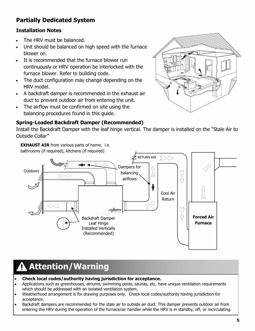
Spring-Loaded Backdraft Damper (Recommended) Install the Backdraft Damper with the leaf hinge vertical. The damper is installed on the “Stale Air to Outside Collar”
Forced Air Furnace
Cool Air Return
Dampers for balancing airflows
Outdoors
Backdraft Damper Leaf Hinge
Installed Vertically (Recommended)
EXHAUST AIR from various parts of home. i.e.bathrooms (if required), kitchens (if required)
RETURN AIR
5
Check local codes/authority having jurisdiction for acceptance. Applications such as greenhouses, atriums, swimming pools, saunas, etc. have unique ventilation requirements
which should be addressed with an isolated ventilation system. Weatherhood arrangement is for drawing purposes only. Check local codes/authority having jurisdiction for
acceptance. Backdraft dampers are recommended for the stale air to outside air duct. This damper prevents outdoor air from
entering the HRV during the operation of the furnace/air handler while the HRV is in standby, off, or recirculating.
Attention/Warning
Fully Dedicated System
Installation Notes
The HRV must be balanced. When balancing, all external exhaust systems should be
turned off (i.e. range hood, dryer exhaust, bathroomvents).
All exhausting appliances should have their own make-upair, as this is not an intended use of the HRV system.
The duct configuration may change depending on theHRV model.
The airflow must be confirmed on site using the balancingprocedures found in this guide.
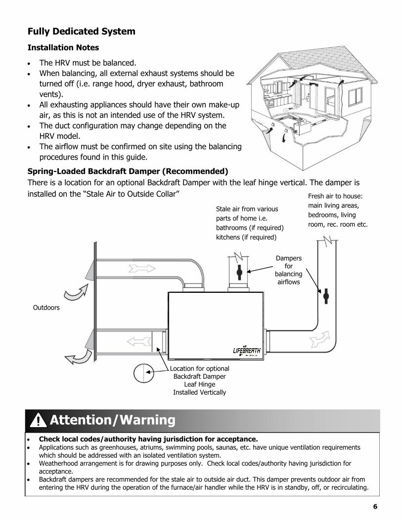
Spring-Loaded Backdraft Damper (Recommended) There is a location for an optional Backdraft Damper with the leaf hinge vertical. The damper is installed on the “Stale Air to Outside Collar”
Outdoors
Dampers for
balancing airflows
Stale air from various parts of home i.e. bathrooms (if required) kitchens (if required)
Fresh air to house: main living areas, bedrooms, living room, rec. room etc.
Location for optional Backdraft Damper
Leaf Hinge Installed Vertically
6
Check local codes/authority having jurisdiction for acceptance. Applications such as greenhouses, atriums, swimming pools, saunas, etc. have unique ventilation requirements
which should be addressed with an isolated ventilation system. Weatherhood arrangement is for drawing purposes only. Check local codes/authority having jurisdiction for
acceptance. Backdraft dampers are recommended for the stale air to outside air duct. This damper prevents outdoor air from
entering the HRV during the operation of the furnace/air handler while the HRV is in standby, off, or recirculating.
Attention/Warning

7
Hanging Straps - Installation Notes (except RNC4-TPD/TPF)
Use 4 screws and 4 washers (not provided) to attach the hanging straps to the floor joists. The washer must be wider than the eyelet of the grommet on the hanging strap. The hanging straps are designed to reduce the possibility of noise, resonance and harmonics.
Must push up on the bottom of the HRV when pulling the hanging straps.
Attention
Step 3: Hook the bottom grommets of thestraps through the “S” hooks. Pull down vertically on the handle loops while lifting the bottom of the unit.
Step 1: Insert the screws and washers(not included) through the hanging strap grommets and fasten to the joists.
Figure A
Step 4: Level the unit from right to left to rightand front to back. Adjust the unit up by pulling down vertically on the hand loops while lifting up on the bottom of the cabinet.
Step 5: Fold the hand loops in excess strapand secure with a nylon tie (not included).
Figure B
Screws (not included)
Hand Loops
Hanging Strap Grommets Washers (not included) Buckles
Hand Loops
Note: Pull down on thehand loops while lifting
Screws
“S” Hooks
Note: This illustration of the unit may vary from thediagram shown.
Joist
Buckles
Figure C
Step 2: Unscrew the 4 machine screws locatedon the upper side of the unit. Attach the “S” hooks and reinsert the machine screws.
7

Mounting the RNC4-TPD and RNC4-TPF Units:
8
Four Mounting Points
1. Begin by locating the four mounting tabs onthe left and right sides of the unit, at the frontand back.
2. Using a flat / slot screwdriver, bendout the four tabs to approximately 45o.
3. Once the tabs have been all bent outwards,insert the "S" hooks through the four holes onthe tabs.
4. Continue with mounting the HRV using theinstructions found on page 8.

9
The HRV and all condensate lines must be installed in a space where the temperature is maintained above thefreezing point or freeze protection must be provided.
Drain trap and tubing must be below bottom of door with 1/4 in per foot downwards slope away from unit. A secondary drain pan may be required to protect from condensate leakage.
Drain Connection
Installation Notes (except RNC4-TPD/TPF see page 10)
The HRV cabinet has pre-punched holes for the drain (see below).The HRV may produce some condensation during a defrost cycle. This water should flow into a nearby drain, or be taken away by a condensate pump.
1.
Pour a cup of water into the drain pan of the HRV after the drain connection is complete. Thiscreates a water seal which will prevent odours from being drawn up the hose and into the fresh airsupply of the HRV.
Caution
Hard Pipe Plumbing
To Drain
Pre-Punched Holes (2)
Drain Pan Drain Pan
1/2 in Hard Pipe Tee Joint
Drain Spout
Drain Hose Plumbing
Drain Spout
1/2 in I.D. Drain Hose
Tee Connector
To Drain
Zip Tie
Drain Spout
Drain Pan Drain Pan
Pre-Punched Holes (2)
7.
The HRV cabinet has pre-punched holes for the drain (see below).
Insert the drain spout through the hole in the drain pan.
2. Tighten the nut which holds the drain spout in place.3. Construct a P-trap using the plastic tee connector. (see below)4. Cut two lengths of 1/2 in drain hose (not included) and connect the other ends to the two drain spouts.5. Position the tee connector to point upward and connect the drain line.6. Tape or fasten base to avoid any kinks.

10
The HRV and all condensate lines must be installed in a space where the temperature is maintained above thefreezing point or freeze protection must be provided.
Drain trap and tubing must be below bottom of door with 1/4 in per foot downwards slope away from unit. A secondary drain pan may be required to protect from condensate leakage.
Drain Connection For RNC4-TPD and RNC4-TPF models Installation Notes
The HRV cabinet has pre-punched holes for the drain (see below).The HRV may produce some condensation during a defrost cycle. This water should flow into a nearby drain, or be taken away by a condensate pump. 1.2. Insert the drain spout through the hole in the drain pan.
3. HAND TIGHTEN the nylon nut which will hold the drain spout in place.4.5.
Construct a P-trap using the plastic tee connector.Cut two lengths of 1/2 in drain hose (not included) and connect the other ends to the two drain spouts.
6. Position the tee connector to point upward and connect the drain line.7. Tape or fasten to avoid any kinks.8. Pour a cup of water into the drain pan of the HRV after the drain connection is complete. This
creates a water seal which will prevent odours from being drawn up the hose and into the fresh airsupply of the HRV.
Caution
Hard Pipe Plumbing
To Drain
Pre-Punched Holes (2)
Drain Pan Drain Pan
1/2 in Hard Pipe Tee Joint
Drain Spout
Drain Hose Plumbing
Drain Spout
1/2 in I.D. Drain Hose
Tee Connector
To Drain
Zip Tie
Drain Spout
Drain Pan Drain Pan
Pre-Punched Holes (2)
The HRV cabinet has pre-punched holes for the drain (see below).
CAUTION: HAND TIGHTEN ONLY
Ensure that the drain spout has a foam gasket on the bottom of the head. See figure below.
Foam Gasket

Adjustable grilles should be used to balance the flow rates into and out of various rooms. The grilles should not be adjusted after balancing the unit.
Grilles or diffusers should be positioned high on the wall or in the ceiling. Kitchen exhaust should never be connected to the range hood. They should be installed at least 4 ft (1.2 m) horizontally away from the stove.
Field supplied balancing dampers should be installed external to the unit to balance the amount of stale air being exhausted with the amount of fresh air being brought into the house. Refer to airflow balancing section.
The Lifebreath Kitchen Grille includes a removable grease filter. Most building codes require that kitchen grilles are equipped with washable filters.
The Lifebreath Kitchen Grille
(part# 99-10-002 6 in x 10 in)
The Lifebreath TechGrille
The TechGrille is a round, fully adjustable grille, which provides quiet air distribution.
Grilles
4 in (100 mm) Part # 99-EAG4
5 in (125 mm) Part # 99-EAG5
6 in (150 mm) Part # 99-EAG6
8 in (200 mm) Part # 99-EAG8
Removable Filter
Airflow
Supply
Airflow
Exhaust
11

12
Do not mount exhaust grille within 4 ft (1.2 m) (horizontally) of a stove to prevent grease from entering the unit.
Caution
Grille Fittings
Stack Head Elbow (part # 99-WF4 / 99WF6) Use this rough-in fitting before the drywall is installed. This fitting is ideal for running ducting through 2 x 4 (min.) studded walls.
Nail to stud. Available sizes are 4 in and 6 in.
Nail stack head elbow onto stud
2 x 4 Stud
1/2 in drywall
Stack Head Elbow
Connect to HRV ducting
TechGrille
Suspended Ceiling Fitting (part # 99-CF6) Use this fitting for ceiling tiles or finished/installed drywall.
Cut a hole through the ceiling tile, insert the fitting and use theretaining ring to hold the fitting in place.
For finished/installed drywall, use caulking around the lip if you donot have access to attach the retaining ring.
Available size: 6 in.
Connect to HRV ducting
Ceiling Fitting
Retaining ring
Flush mount the lip of the ceiling fitting to ceiling
TechGrille
Ceiling
Quick Mount Fitting (part # 99-QM6) Use this rough-in fitting before the drywall is Installed.
Nail fitting onto the stud. Available size: 6 in.
Connect to HRV ducting
2 x 4 Stud
Nail or screw quick mount fitting to stud
TechGrille
1/2 in drywall
Quick Mount Fitting
Terminator Fitting (part # 99-TM 4/5/6) Use this rough-in fitting before the drywall is installed.
TechGrille
Connect to HRV ducting
TerminatorFitting
Ceiling / wall drywall
Nail / screw to secure stud or joist
Flush mount the lip of the Terminator fitting to the drywall
Nail or screw fitting onto the stud or joist. Available sizes: 4 in, 5 in and 6 in. Use this rough-in fitting before the drywall is installed. Adapts to ridged and flex ducting Strong attachment for grilles, either vertically or horizontally

Lifebreath Weatherhood
Fixed covered weatherhoods have a built-in bird screen with a 1/4 in (6 mm) mesh to prevent foreign objects from entering the ductwork.
Installation Notes The inner and outer liners of the flexible insulated duct must be clamped to the sleeve of the weatherhoods (as close to the outside as possible) and the appropriate port on the HRV. It is very important that the fresh air intake line be given special attention to make sure it is well sealed. A good bead of high quality caulking (preferably acoustical sealant) will seal the inner flexible duct to both the HRV port and the weatherhood prior to clamping. The flexible insulated duct that connects the two outside weatherhoods to the HRV should be stretched tightly and be as short as possible to minimize air flow restrictions. Twisting or folding the duct will severely restrict airflow. Hard (rigid) ducting which has been sealed and insulated should be used for runs over 10 ft (3.3 m). Refer to your local building code.
Screen (side view)
1/4 in (6 mm) Screen
Exterior wall
Collar is supplied to ensure vapor barrier is
100% sealed to wall plate
12 in galvanized pipe supplied
13
Weatherhood Requirements
Check local codes/authority having jurisdiction for acceptance and spacingrequirements for weatherhoods. Do not locate in garage, attic or crawl space.Intake: Should be located upstream (if there are prevailing winds) from the exhaust outlet. Not near dryer vents, furnace exhaust, driveways, oil fill pipes, gas meters, or garbagecontainers.Exhaust: Not near a gas meter, electric meter or a walkway where fog or ice could create a hazard.
Contact your local building authority before installation of the Dual Hood to verify compliance withlocal building codes.
Attention
Contact your local building authority before installation of the Dual Hood to verify compliance withlocal building codes.
Caution: Sealant must be applied as per instructions or leakage and condensation may occur. Insulate the Fresh Air Supply and Stale Air Exhaust duct work back to the unit.
Attention/Caution
14
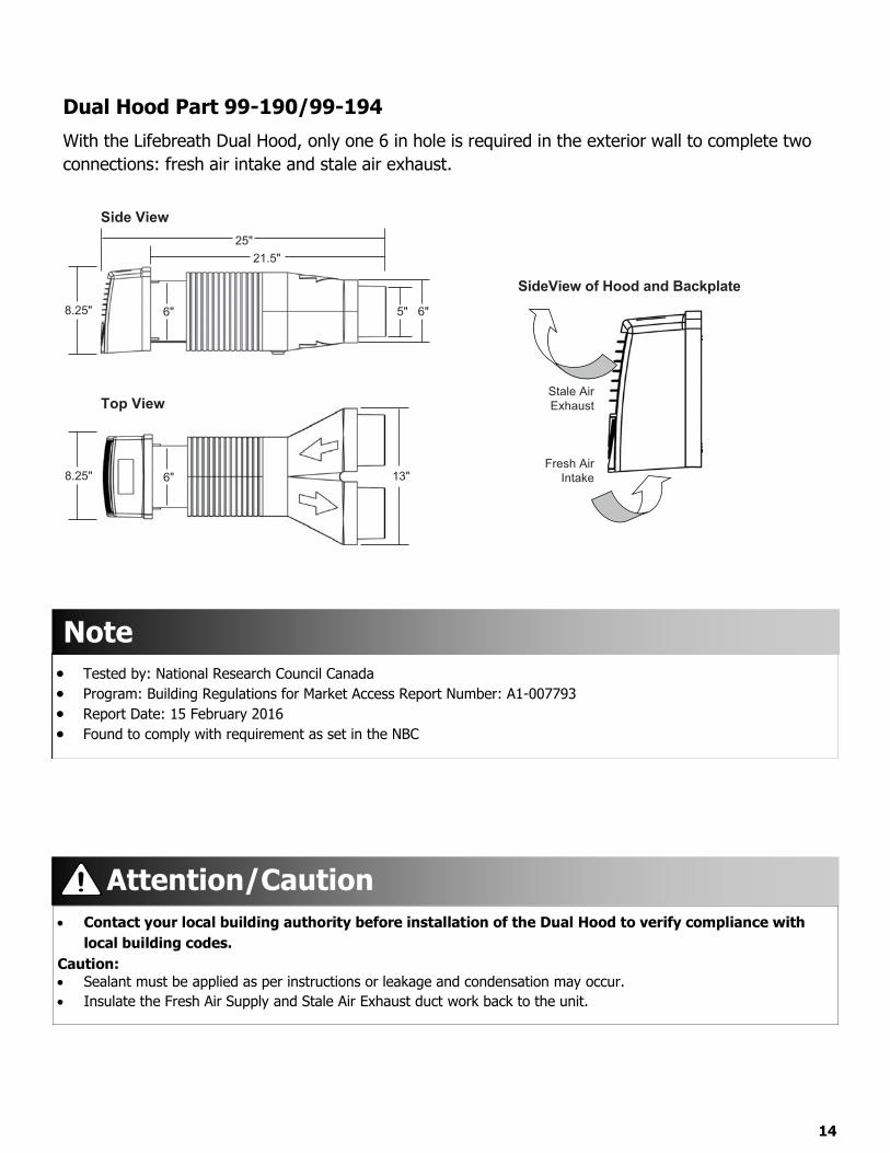
Dual Hood Part 99-190/99-194With the Lifebreath Dual Hood, only one 6 in hole is required in the exterior wall to complete two connections: fresh air intake and stale air exhaust.
13"
Top View
8.25" 6"
8.25"
25"
Side View
6" 5" 6"
21.5"
Stale AirExhaust
Fresh AirIntake
SideView of Hood and Backplate
Tested by: National Research Council Canada Program: Building Regulations for Market Access Report Number: A1-007793 Report Date: 15 February 2016 Found to comply with requirement as set in the NBC
Note

15
Main Control Installation The Lifebreath Digital Control 99-DXPL02 is to be surface mounted onto a wall and the Lifebreath Ventilation Controls 99-BC02, 99-BC03 and 99-BC04 may either be installed onto a flush mounted electrical switch box or surface mounted onto a wall. Only one master control should be installed to a ventilation system (the face plate on this illustration may not be exactly the same as yours).
1. For DXPL02 control, remove the operatinginstructions card from the top of the control(Figure A).
2. Separate the face plate from the back plate byfirmly pulling apart (Figures B or C). Be carefulnot to damage face plate contact pins.
3.
4.
5.
6.
7.
8.
9.
Operating Instruction
Card
1 in hole for Wiringwire opening. Terminals
10.
11.
12.
For DXPL02 control, place the back plate ofthe control in the desired location on the wall
Keep top / bottomand pencil mark the wall with the right and left Figure A Figure B vent openings clearscrew holes (Figure D).
For BC02, BC03 or BC04 controls, place the Figure C Back Plate (Two) 1/8 in hole forscrews and anchors.
back plate of the control in the desired location Face Plateon the wall and pencil mark the top and bottomscrew holes
1.5" 1.5"(Figure E or F). For mounting the controlwithout a Decora plate, break off top andbottom tabs and refer to Figure F for mounting.Remove the back plate from the wall and markthe center hole for the wires in the middle ofthe screw holes. Refer to Figure D, E or F fordimensions.Drill (two) 1/8 in holes for the screws and wall
anchors (Figure D, E or F). For DXPL02 control, vent openings clear
Figure Ddrill a 1 in hole in the center (Figure D). For BC04 controls, cut in a 3/4 in by 1 in oval hole in the wall (Figure E or F).Pull 3 wire 20 gauge (min.) 100 ft length(max.), through the opening in the wall.
terminals located on the back plate (Figure D, E
supplied screws and anchors.Attach the face plate to the back plate (Figure B or C). Note: Be careful to correctly align the face plate to avoid damaging the face plate contact pins.
instructions card into the control (Figure A).
Connect the 3 wire 20 gauge (min.) 100 ft length (max.) to the terminal block located on ventilator (Red #3, Yellow #4 and Green #5).
Face Plate
Back Plate
Pay special attention not to damage the contact pins when removing and detaching the face plate (Figures B and C).
Attention
Keep top / bottom
For DXPL02 control, insert the operating Figure E
1.625"
Connect red, green, and yellow to the wiring 0.75"
or F). 1"
1.625"
1/8 in hole for screw and anchor
1 in x 3/4 in
for wire opening
WiringTerminals
1/8 in hole for screw and anchor
oval hole
Break off tab
Alternate Wall Mount
1/8 in hole for screw and anchor
1 in x 3/4 in oval hole
1/8 in
for wire
hole for
opening
screw and anchor
WiringTerminals
Break off tab
Figure F
Attach the back plate to the wall using two 1"
Wire hole centered between screw holes
0.75"

16
Mechanical Timers Installation 99-101The Mechanical Timer is a 2 wire “dry contact” timer. A jumper wire must be connected between 2 (ON) and 3 (RED). Connect the 2 timer wires to ON and HI.
2 wire timers require a jumper wire between ON and RED on the terminal block Connect the 2
wires from the timer to ON and HI on the terminal block.
HRV Terminal Block Wire Connector
Furnace Terminal Strip
Furnace Thermostat
Interlocking the HRV to an Air Handler or Furnace BlowerConnecting the HRV as illustrated will ensure the air handler/furnace blower motor is operating whenever the HRV is venting. The HRV must be interlocked to the furnace/air handler with a simplified installation (return/return installation) and should be interlocked with a partially dedicated installation.
Setting “Standby” When Using a Main ControlThe HRV will be “fully-off” when the off position is selected on the
Timers mount in standard electrical boxes Use 3 wire 20 gauge (min.) 100 ft length (max.) low voltage wire and multiple timers individually wired back to the unit.Caution: Consideration should be given to competing airflows when connecting the HRV in conjunction with an air handler/furnaceblower system. Building codes in some areas require “fully-off” functionality. Check with your local building authority before modifying theunit to“standby-off”. Unintentional operation of the HRV by the end user may occur if the unit is modified from “fully-off” to“standby-off”.
Attention/Caution
Main Control. Timers and/or other controls will not function when the HRV is in the off position. The “fully-off” feature can be modified to “standby-off” by adding a jumper on the terminal block between 2 (ON) and 3 (RED). “Standby” can also be achieved by setting the main control to the ON position and selecting speed 0*. Timers and/or additional controls will initiate high speed ventilation when activated. *Speed 0 is not available on all controls.
Operating the HRV With Dry Contact ControlsA jumper must be in place between 2 (ON) and 3 (RED) on the terminal block to activate the HRV for timers and/or dry contact controls.
Adding Dry Contact ControlsLow Speed: A jumper between 2 (ON) and 1 (LOW) initiates low speed ventilation. High Speed: A jumper between 2 (ON) and 6 (HI) initiates high speed ventilation. Dehumidistat: A dry contact for a Dehumidistat is connected between 2 (ON) and 10 (BLK)

Installation and Operation of Wireless 20/40/60 Minute Timer: 99-DET02
17
BC02, BC03 or BC04 Control
NOTE: Your control may look different than the one shown.
Press Simultaneously to Initiate Pairing Mode
Figure A
Figure D
NOTEThe wireless Timers and Repeaters must be matched to the main wall control of the HRV / ERV. This process is called "Pairing". Multiple Timers and Repeaters can be paired to a single wall control.
Figure B
1/8 in hole for screw and anchor
1/8 in hole for screw and anchor
Break off tab
Alternate Wall Mount
1/8 in hole for screw and anchor
Figure C
Back Plate
Face Plate
1/8 in hole for screw and anchor
Break off tab
Figure F Figure E
Press Simultaneously to Initiate Pairing Mode
DXPL02 Control
DET02 Timer
20/40/60 Minute Status Lights
Select Button initiates high speed ventilation for 20, 40 or 60 min.
Battery Indicator
Removable Backplate
The Timers may be installed onto a flush mounted electrical switch box or it may be surface mounted onto a wall. Multiple Timers may be installed in a ventilation system. To increase the range of a wireless Timer, a RX02 Repeater should be used.
Pairing:
To pair additional DET02 Timers with the same wall control, or if pairing was not successful, repeat steps 1-6.
When paired, the DET02 Timers can be moved and installed elsewhere. Estimated range of the Timer is 40’ with no obstructions. A RX02 Repeater may be installed to increase the range of the Timers.
Test if pairing was successful by pressing the Select Button and listen for the HRV / ERV to initiate HIGH fan speed Ventilation.
Un-pairing:
Installation:
1. Turn on the main wall control by pressing the ON/OFFbutton and remove the battery from Timer.
2. DET02 with DXPL02 Controls: Press the left and rightbuttons simultaneously on the main wall control( and RESET buttons). The screen will go blank and thewireless symbol will appear flashing on the bottom rightof the display. This indicates that the main control is nowin pairing mode. (Figure D)
3. DET02 with BC02, BC03 or BC04 Controls: Pressthe left and right buttons simultaneously on the main wallcontrol ( and either or buttons, depending on themain control). The bottom row of 3 LED's will beginflashing. This indicates that the main control is now inpairing mode.(Figure E)
4. Keep the Timer within 16” of the main wall control whenpairing.
5. Install the battery in the DET02 Timer. All four lights onthe Timer will immediately flash 5 times, then only the redbattery light will remain on for approximately 12 secondsafter which the "40" light flashes the rev code. 20, 40, 60lights will flash until paired or will stop if not paired within12 seconds. If pairing was not successful you now mustreturn to step 1 to restart the pairing process.
6. Press the button on the main wall control to exit pairingmode when Timers have been successfully paired.
1. Remove the battery from the back of the DET02 Timer
2. Press and hold the Select Button on the front of the Timer
3. While holding the Select Button, reinsert the battery in theTimer. Continue holding the select button until the LEDunder "40" begins flashing. The DET02 Timer will now beunpaired with the main wall control.
1. Separate the face plate from the back plate by firmlypulling apart (Figure A).
2. For mounting the control without a Decora plate, break off top and bottom tabs and refer to Figure C for mounting.
3. Place the back plate of the control in the desired location on the wall and pencil mark the top and bottom screw holes(Figure B or C). Drill two 1/8" holes.
4. Attach the back plate to the wall using the 2 supplied screws and anchors.
5. Attach the face plate to the back plate (Figure A).
18
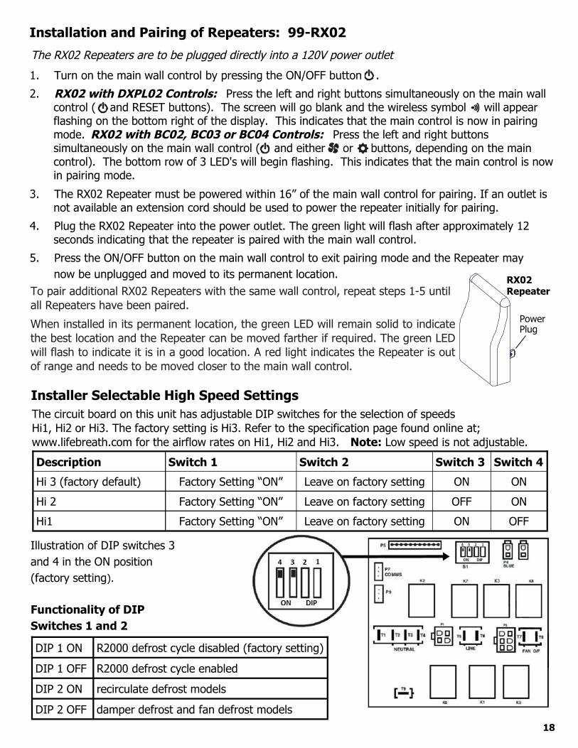
The circuit board on this unit has adjustable DIP switches for the selection of speeds Hi1, Hi2 or Hi3. The factory setting is Hi3. Refer to the specification page found online at; www.lifebreath.com for the airflow rates on Hi1, Hi2 and Hi3. Note: Low speed is not adjustable.
DIP 1 ON R2000 defrost cycle disabled (factory setting)
DIP 1 OFF R2000 defrost cycle enabled
DIP 2 ON recirculate defrost models
DIP 2 OFF damper defrost and fan defrost models
Illustration of DIP switches 3 and 4 in the ON position (factory setting).
Functionality of DIP Switches 1 and 2
Description Switch 1 Switch 2 Switch 3 Switch 4
Hi 3 (factory default) Factory Setting “ON” Leave on factory setting ON ON
Hi 2 Factory Setting “ON” Leave on factory setting OFF ON
Hi1 Factory Setting “ON” Leave on factory setting ON OFF
1. Turn on the main wall control by pressing the ON/OFF button .
2. RX02 with DXPL02 Controls: Press the left and right buttons simultaneously on the main wallcontrol ( and RESET buttons). The screen will go blank and the wireless symbol will appearflashing on the bottom right of the display. This indicates that the main control is now in pairingmode. RX02 with BC02, BC03 or BC04 Controls: Press the left and right buttonssimultaneously on the main wall control ( and either or buttons, depending on the maincontrol). The bottom row of 3 LED's will begin flashing. This indicates that the main control is nowin pairing mode.
3. The RX02 Repeater must be powered within 16” of the main wall control for pairing. If an outlet isnot available an extension cord should be used to power the repeater initially for pairing.
4. Plug the RX02 Repeater into the power outlet. The green light will flash after approximately 12seconds indicating that the repeater is paired with the main wall control.
5. Press the ON/OFF button on the main wall control to exit pairing mode and the Repeater may
RX02Repeater
PowerPlug
Installation and Pairing of Repeaters: 99-RX02
The RX02 Repeaters are to be plugged directly into a 120V power outlet
now be unplugged and moved to its permanent location.To pair additional RX02 Repeaters with the same wall control, repeat steps 1-5 until all Repeaters have been paired.
When installed in its permanent location, the green LED will remain solid to indicate the best location and the Repeater can be moved farther if required. The green LED will flash to indicate it is in a good location. A red light indicates the Repeater is out of range and needs to be moved closer to the main wall control.
Installer Selectable High Speed Settings

19
Installation and Operation 20/40/60 Minute Timer: 99-DET01
Status Lights
Select Button initiates high speed ventilation for 20, 40 0r 60 min.
Yellow Red Green
InstallationThe 99-DET01 Timers are to be surface mounted onto a wall. Multiple Timers may be installed in a system. Once mounted, connect Yellow, Red, Green wires on side of 99-DET01 to the terminal block on unit using 3 wire 20 gauge (min.) 100 ft length (max.).
Operating the Timer Press and release the Select Button to activate a 20, 40 or 60 minute HIGH speed override cycle. The Light will illuminate and the unit will run on HIGH speed Ventilation for the selected time. The Light will dim after 10 sec. for run time. The Light will flash during the last 5 min. of the cycle. The Timer connected to the unit will illuminate for the duration of the override when the Select Button is pressed.
Lockout Mode Lockout Mode is useful if you wish to disable the Timers. The Timer can be set to lockout mode by pressing and holding the Select Button for five seconds. After 5 sec., the Light will flash; release the Select Button. The Timer is now in lockout mode. If the Select Button is pressed during lockout mode the Light will momentarily illuminate but no override will be initiated.
If lockout mode is initiated when the Timer is activated, the Timer will continue its timed sequence but will not allow any further overrides to be initiated. Lockout mode can be unlocked by pressing and holding the Select Button for 5 sec. After 5 sec. the Light will stop flashing. Release the Select Button and the Timer will now operate normally.

20
Dim ensional Drawing for RNC4-TPF Model
Dim ensional Drawing for RNC4-TPD Model
Note: Front clearance of 25 in (635 mm) is recommended for servicing unit. All ducts use 4 in (102 mm) round collars, balancing dampers are located in all air streams.
17 7/8" (454 mm)
Top View Front View
Fresh Air To Inside
Stale Air To Outside
Stale Air From Inside
Fresh Air From Outside
18 3
/4" (
476
mm
)
19 1
/4" (
489
mm
)
Note: Front clearance of 25 in (635 mm) is recommended for servicing unit. All ducts use 4 in (102 mm) round collars, balancing dampers are located in all air streams.
17 7/8" (454 mm)
Top View Front View
18 3
/4" (
476
mm
)
19 1
/4" (
489
mm
)

Dimensional Drawing for RNC5-HEX-TPD Model
21
17 1
/4 in
(43
8 m
m)
29 1/8 in (740 mm)
15 in
(38
1 m
m)
Front View
Top View
Fresh Air From Outside
Stale Air To
Outside
Fresh Air To
Inside
Stale Air From
Inside
Motorized Impellers
Condensate Drains
Removable Heat Recovery
Core
Recirculating Defrost Damper
Filters
Note: Front clearance of 25 in (635 mm) is recommended for servicing unit. All ducts use 5 in (125 mm) oval collars, balancing dampers are located on all collars.
Dimensional Drawing for RNC5-HEX-TPF Model17
1/4
in (
438
mm
)
29 1/8 in (740 mm) 15
in (
381
mm
)
Front View
Top View
Fresh Air From Outside
Stale Air To
Outside
Fresh Air From Air To
Inside
Stale
Inside
Motorized Impellers
Condensate Drains
Removable Heat Recovery
Core
Filters
Note: Front clearance of 25 in (635 mm) is recommended for servicing unit. All ducts use 5 in (125 mm) oval collars, balancing dampers are located on all collars.

Dimensional Drawing for RNC5-TPD/TPF/RNC6-ES Models
22
17 1
/4 in
(43
8 m
m)
22 3/4 in (578 mm)
14 in
(35
6 m
m)
Front View
Top View
Fresh Air From Outside
Stale Air To
Outside
Fresh Air To Inside
Stale Air From
Inside
Motorized Impellers
Condensate Drains
Removable Heat Recovery
Core
Recirculating Defrost Damper (For TPD Model
Only)
Filters
Note: Front clearance of 25 in (635 mm) is recommended for servicing unit. All ducts use 5 in (125 mm) oval collars, balancing dampers are located on all collars.
Dimensional Drawing for 95 Model
Dimensional Drawing for 155 Model
Blower
Removable Heat Recovery
Core
Condensate Drain
18 1/2 in (469 mm)
Front View
Fresh Air From Outside
Fresh Air To Inside
Stale Air To
Outside
Stale Air From Inside
Top View
Note: Front clearance of 25 in (635 mm) is recommended for servicing unit. Round duct connections are 5 in (127 mm) and oval collars use 6 in (152 mm) connections.
25
in (
635
mm
) 16in (406 mm
)
Side View
18 3/4 in (476 mm
)
14 3/4 in (375 mm)
Note: Front clearance of 25 in (635 mm) is recommended for servicing unit. All ducts use 6 in (152 mm) connections.Stale
Air To Outside
Removable Heat
Recovery Core
Recirculating Defrost Damper
Fresh Air From Outside
Stale Air From Inside
33 5/8 in (854 mm)
Condensate Drain Front View
Filter
Fresh Air To Inside
Motor
Blower
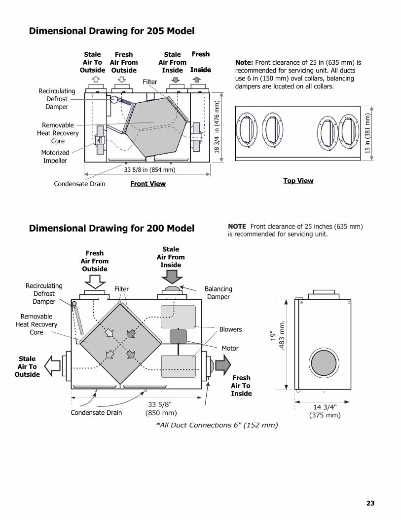
Dimensional Drawing for 205 Model
Note: Front clearance of 25 in (635 mm) is recommended for servicing unit. All ducts use 6 in (150 mm) oval collars, balancing dampers are located on all collars.
Top View
Fresh Air From Outside
Fresh
Air To
Inside
Stale Air From Inside
Stale Air To
Outside
Motorized Impeller
Recirculating Defrost Damper
Removable Heat Recovery
Core
33 5/8 in (854 mm)
Filter
18 3
/4 i
n (4
76 m
m)
Front View Condensate Drain
15 in
(38
1 m
m)
Dimensional Drawing for 200 Model
Recirculating Defrost Damper
Removable Heat Recovery
Core
Stale Air To
Outside
Fresh Air From Outside
Stale Air From Inside
Fresh
Inside
Fresh
Inside
Condensate Drain
Blowers
Motor
Balancing Damper
NOTE: Front clearance of 25 inches (635 mm) is recommended for servicing unit.
33 5/8"(850 mm)
14 3/4"(375 mm)
19"
(483
mm
)
*All Duct Connections 6" (152 mm)
Filter
23

24
Balancing the Airflows
Balan cing the airflows is critical to ensuring that the amount of air introduced from the outside of the building equals the amount of air exhausted to the outside of the building. If these two airflows are not properly balanced, the following issues may occur:
A positive or negative pressure in the house HRV not operate at its maximum efficiency The unit not defrost properly
Airflow Measuring Gauge A digital manometer is a suitable instrument for the balancing of airflows. 99-BAL-KIT Airflow Balancing KitKit includes a digital manometer, pitot tube, hose and tool bag. Figure A
Digital Manometer
Continuous, excessive, positive pressure may drive moist indoor air into the external walls of the building. Onceinside the external walls, moist air may condense (in cold weather) and degrade structural components or causelocks to freeze.
Continuous, excessive, negative pressure may have several undesirable effects. In some geographic locations, soilgases such as methane and radon gas may be drawn into the home through basement or ground contact areas,and may also cause the backdrafting of vented combustion equipment.
Attention
�� ��
DICITAL IANDIETER
25
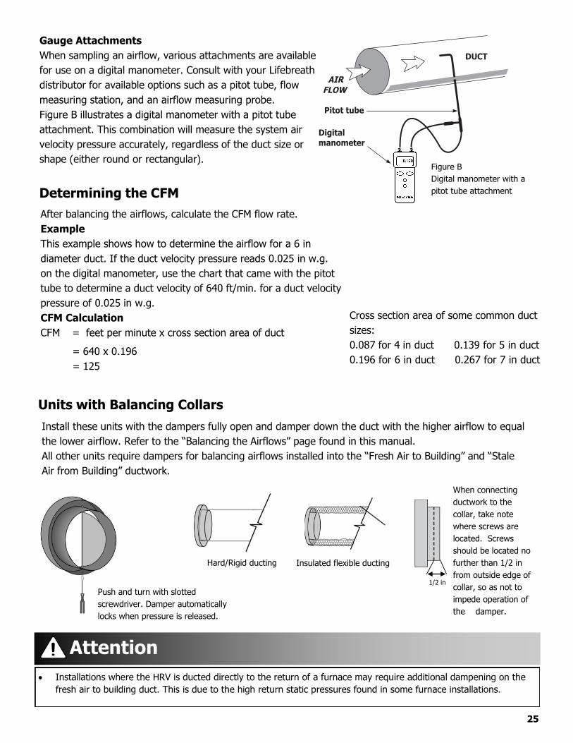
After balancing the airflows, calculate the CFM flow rate. Example This example shows how to determine the airflow for a 6 in diameter duct. If the duct velocity pressure reads 0.025 in w.g. on the digital manometer, use the chart that came with the pitot tube to determine a duct velocity of 640 ft/min. for a duct velocity pressure of 0.025 in w.g.CFM CalculationCFM = feet per minute x cross section area of duct
= 640 x 0.196 = 125
Cross section area of some common duct sizes: 0.087 for 4 in duct 0.196 for 6 in duct
0.139 for 5 in duct 0.267 for 7 in duct
Units with Balancing CollarsInstall these units with the dampers fully open and damper down the duct with the higher airflow to equal the lower airflow. Refer to the “Balancing the Airflows” page found in this manual. All other units require dampers for balancing airflows installed into the “Fresh Air to Building” and “Stale Air from Building” ductwork.
When connecting ductwork to the collar, take note where screws are located. Screws should be located no further than 1/2 in from outside edge of collar, so as not to impede operation of the damper.
1/2 in Push and turn with slotted screwdriver. Damper automatically locks when pressure is released.
Hard/Rigid ducting Insulated flexible ducting
Installations where the HRV is ducted directly to the return of a furnace may require additional dampening on thefresh air to building duct. This is due to the high return static pressures found in some furnace installations.
Attention
Gauge Attachments When sampling an airflow, various attachments are available for use on a digital manometer. Consult with your Lifebreath distributor for available options such as a pitot tube, flow measuring station, and an airflow measuring probe. Figure B illustrates a digital manometer with a pitot tube attachment. This combination will measure the system air velocity pressure accurately, regardless of the duct size or shape (either round or rectangular).
Determining the CFM
Figure B Digital manometer with a pitot tube attachment
DUCT
AIRFLOW
Pitot tube
Digital manometer
26
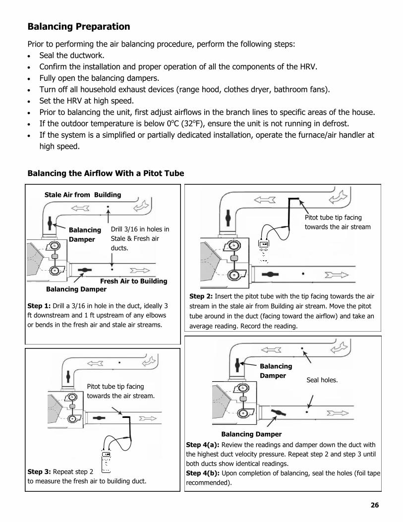
Balancing Preparation
Prior to performing the air balancing procedure, perform the following steps: Seal the ductwork. Confirm the installation and proper operation of all the components of the HRV. Fully open the balancing dampers. Turn off all household exhaust devices (range hood, clothes dryer, bathroom fans). Set the HRV at high speed. Prior to balancing the unit, first adjust airflows in the branch lines to specific areas of the house. If the outdoor temperature is below 0oC (32oF), ensure the unit is not running in defrost. If the system is a simplified or partially dedicated installation, operate the furnace/air handler at
high speed.
Balancing the Airflow With a Pitot Tube
Step 2: Insert the pitot tube with the tip facing towards the airstream in the stale air from Building air stream. Move the pitot tube around in the duct (facing toward the airflow) and take an average reading. Record the reading.
Step 3: Repeat step 2to measure the fresh air to building duct.
Pitot tube tip facing towards the air stream.
Balancing Damper
Drill 3/16 in holes in Stale & Fresh air ducts.
Fresh Air to Building Balancing Damper
Step 1: Drill a 3/16 in hole in the duct, ideally 3ft downstream and 1 ft upstream of any elbows or bends in the fresh air and stale air streams.
Stale Air from Building
Pitot tube tip facing towards the air stream
Balancing Damper
Step 4(a): Review the readings and damper down the duct withthe highest duct velocity pressure. Repeat step 2 and step 3 until both ducts show identical readings. Step 4(b): Upon completion of balancing, seal the holes (foil taperecommended).
Seal holes.
Balancing Damper

27
Balancing the Airflow using the Door Ports
Door balancing ports (not on all models) are designed to be used in the conjunction with a digital manometer to measure the stale and fresh airflows for balancing.
Step 1: Prepare the airflow measuring device by connecting the hoses to the low and high pressure side of the gauge.
Step 2: Insert the hoses into the rubber fittings from the optional door port adapter kit (part 99-182). Use light pressure and rotate until fitting is snug. Do not extend the hose past the rubber fitting.
Step 3: Open the HRV door. Remove the 4 door port covers by carefully pushing them out from the back side of the door.
Step 4: Close the HRV door. Initiate power and operate the HRV on high speed. Operate the forced air system on high speed (if the HRV is connected to the forced air system).
Step 5: Insert the 2 rubber fittings from the gauge to the stale air balancing ports (see illustrations for port locations). Seal the fresh air balancing ports with tape (see illustrations for port locations). Record your reading.
Step 6: Insert the 2 rubber fittings from the gauge to the fresh air balancing ports (see illustrations for port locations). Seal the stale air balancing ports with tape (see illustrations for port locations). Record your reading.
Step 7: Refer to the “Airflow Reference Chart” for your model and determine the fresh air and stale airflow rates (the chart is located on page 23).
Step 8: Damper down the higher airflow and repeat Steps 5 to 7 as required until both airflows are identical (balanced).
Step 9: Remove the tape and rubber fittings and reinstall the 4 Door Port Covers.
Reverse Flow Models: Step 5 and Step 6 stale air and stale air ports will be reversed.
Attention

ExhaustBalancing Ports
SupplyBalancingPorts
High (+)
High (+)
Low (-) Low
(-)
Digital manometer connection overview
Balancing Ports for RNC155 Model Balancing Ports for RNC5-TPD/FD/RNC6-ES, RNC5-HEX-TPD/TPF and RNC205 Models
SupplyBalancing Ports
ExhaustBalancing Ports High
(+)
High (+)
Low (-)
Low (-)
ExhaustBalancing Ports
High (+)
Low (-)
SupplyBalancing Ports
High (+)
Low (-)
Balancing Door Port illustrations
Balancing Ports for RNC4-TPD and TPF
ExhaustBalancing Ports
SupplyBalancingPorts
High (+)
High (+)
Low (-) Low
(-)
Balancing Ports for RNC200 Model
28

29
Airflow Reference Charts RNC4-TPD ModelRNC4-TPD models have 3 airflow charts for their installer adjustable high speed settings. Refer to “Installer Selectable High Speed Settings” in this manual for instructions on how to adjust the circuit board DIP switches.
Supply Airflow
Exhaust Airflow
Supply Airflow
Exhaust Airflow
Supply Airflow
Exhaust Airflow
("w.g.) (Pa) (cfm) (cfm) ("w.g.) (Pa) (cfm) (cfm) ("w.g.) (Pa) (cfm) (cfm)0.400 100 74 0.330 83 73 0.280 70 690.410 103 74 0.340 85 72 0.290 73 690.420 105 73 0.350 88 73 72 0.300 75 680.430 108 73 0.360 90 73 71 0.310 78 670.440 110 72 0.370 93 73 70 0.320 80 71 660.450 113 71 0.380 95 73 69 0.330 83 71 650.460 115 75 71 0.390 98 73 69 0.340 85 71 640.470 118 75 70 0.400 100 72 68 0.350 88 70 630.480 120 75 69 0.410 103 72 67 0.360 90 69 620.490 123 74 69 0.420 105 72 66 0.370 93 69 610.500 125 74 68 0.430 108 71 65 0.380 95 68 600.510 128 74 67 0.440 110 71 64 0.390 98 68 590.520 130 74 66 0.450 113 70 63 0.400 100 67 580.530 133 73 65 0.460 115 70 62 0.410 103 66 570.540 135 73 65 0.470 118 69 62 0.420 105 65 560.550 138 73 64 0.480 120 69 61 0.430 108 65 550.560 140 72 63 0.490 123 68 60 0.440 110 64 540.570 143 72 62 0.500 125 67 58 0.450 113 63 520.580 145 71 61 0.510 128 67 57 0.460 115 62 510.590 148 70 60 0.520 130 66 56 0.470 118 61 500.600 150 69 59 0.530 133 65 55 0.480 120 60 490.610 153 69 58 0.540 135 64 54 0.490 123 59 480.620 155 68 57 0.550 138 63 53 0.500 125 58 460.630 158 67 56 0.560 140 62 52 0.510 128 57 450.640 160 66 54 0.570 143 61 51 0.520 130 56 440.650 163 65 53 0.580 145 60 50 0.530 133 55 420.660 165 64 52 0.590 148 59 48 0.540 135 54 410.670 168 62 51 0.600 150 58 47 0.550 138 53 400.680 170 61 50 0.610 153 57 46 0.560 140 52 380.690 173 60 48 0.620 155 56 45 0.570 143 51 370.700 175 58 47 0.630 158 54 43 0.580 145 49 360.710 178 57 46 0.640 160 53 42 0.590 148 48 340.720 180 56 44 0.650 163 52 41 0.600 150 47 330.730 183 54 43 0.660 165 50 39 0.610 153 45 310.740 185 52 41 0.670 168 49 38 0.620 155 44 300.750 188 51 40 0.680 170 47 36 0.630 158 43 280.760 190 49 39 0.690 173 46 35 0.640 160 41 270.770 193 47 37 0.700 175 44 34 0.650 163 40 250.780 195 45 36 0.710 178 43 32 0.660 165 38 240.790 198 43 34 0.720 180 41 31 0.670 168 37 220.800 200 41 32 0.730 183 39 29 0.680 170 35 200.810 203 39 31 0.740 185 37 28 0.690 173 34 190.820 205 37 29 0.750 188 36 26 0.700 175 32 170.830 208 35 27 0.760 190 34 24 0.710 178 300.840 210 33 26 0.770 193 32 23 0.720 180 290.850 213 31 24 0.780 195 30 21 0.730 183 270.860 215 28 22 0.790 198 28 20 0.740 185 250.870 218 26 21 0.800 200 26 18 0.750 188 240.880 220 23 0.810 203 24 0.760 190 220.890 223 21 0.820 205 22 0.770 193 20
0.830 208 19 0.780 195 18
Hi 3 Hi 2 Hi 1
Pressure Drop Pressure Drop Pressure Drop

30
Airflow Reference Charts RNC4-TPF ModelRNC4 Models have 3 airflow charts for their installer adjustable high speed settings. Refer to “Installer Selectable High Speed Settings” in this manual for instructions on how to adjust the circuit board DIP switches.
Supply Airflow
Exhaust Airflow
Supply Airflow
Exhaust Airflow
Supply Airflow
Exhaust Airflow
("w.g.) (Pa) (cfm) (cfm) ("w.g.) (Pa) (cfm) (cfm) ("w.g.) (Pa) (cfm) (cfm)0.300 75 96 0.280 70 81 0.300 75 720.310 78 94 0.290 73 80 0.310 78 720.320 80 93 0.300 75 79 0.320 80 710.330 83 91 0.310 78 79 0.330 83 700.340 85 90 98 0.320 80 78 0.340 85 69 750.350 88 88 96 0.330 83 77 83 0.350 88 69 740.360 90 87 95 0.340 85 76 82 0.360 90 68 720.370 93 85 93 0.350 88 75 81 0.370 93 67 710.380 95 84 91 0.360 90 75 80 0.380 95 66 700.390 98 83 90 0.370 93 74 80 0.390 98 66 690.400 100 82 88 0.380 95 73 79 0.400 100 65 680.410 103 80 87 0.390 98 72 78 0.410 103 64 670.420 105 79 86 0.400 100 72 77 0.420 105 63 660.430 108 78 84 0.410 103 71 76 0.430 108 63 650.440 110 77 83 0.420 105 70 75 0.440 110 62 640.450 113 76 82 0.430 108 70 74 0.450 113 61 630.460 115 75 81 0.440 110 69 74 0.460 115 60 610.470 118 74 80 0.450 113 68 73 0.470 118 59 600.480 120 74 79 0.460 115 67 72 0.480 120 59 590.490 123 73 78 0.470 118 67 71 0.490 123 58 580.500 125 72 78 0.480 120 66 70 0.500 125 57 570.510 128 71 77 0.490 123 65 69 0.510 128 56 560.520 130 70 76 0.500 125 65 68 0.520 130 55 550.530 133 70 75 0.510 128 64 67 0.530 133 55 540.540 135 69 75 0.520 130 63 66 0.540 135 54 530.550 138 68 74 0.530 133 62 66 0.550 138 53 520.560 140 67 73 0.540 135 62 65 0.560 140 52 510.570 143 67 72 0.550 138 61 64 0.570 143 51 500.580 145 66 72 0.560 140 60 63 0.580 145 50 490.590 148 65 71 0.570 143 59 62 0.590 148 49 480.600 150 65 70 0.580 145 58 60 0.600 150 48 460.610 153 64 70 0.590 148 58 59 0.610 153 47 450.620 155 63 69 0.600 150 57 58 0.620 155 46 440.630 158 62 68 0.610 153 56 57 0.630 158 45 430.640 160 62 67 0.620 155 55 56 0.640 160 44 410.650 163 61 66 0.630 158 54 55 0.650 163 43 400.660 165 60 65 0.640 160 53 53 0.660 165 42 380.670 168 60 64 0.650 163 52 52 0.670 168 41 370.680 170 59 63 0.660 165 51 51 0.680 170 40 350.690 173 58 62 0.670 168 50 49 0.690 173 39 340.700 175 57 61 0.680 170 49 48 0.700 175 37 320.710 178 56 59 0.690 173 48 46 0.710 178 36 300.720 180 55 58 0.700 175 47 45 0.720 180 35 280.730 183 54 56 0.710 178 46 43 0.730 183 34 270.740 185 53 55 0.720 180 45 42 0.740 185 32 250.750 188 52 53 0.730 183 44 40 0.750 188 31 230.760 190 51 51 0.740 185 43 38 0.760 190 30 210.770 193 50 50 0.750 188 42 36 0.770 193 280.780 195 49 48 0.760 190 40 34 0.780 195 270.790 198 48 45 0.770 193 39 32 0.790 198 250.800 200 47 43 0.780 195 38 30 0.800 200 240.810 203 46 41 0.790 198 36 28 0.810 203 220.820 205 44 38 0.800 200 35 26 0.820 205 210.830 208 43 36 0.810 203 34 240.840 210 41 33 0.820 205 32 220.850 213 40 30 0.830 208 310.860 215 38 0.840 210 290.870 218 37 0.850 213 270.880 220 35 0.860 215 260.890 223 33 0.870 218 240.900 225 31
Pressure Drop
Hi 3 Hi 2 Hi 1
Pressure Drop Pressure Drop

Airflow Reference Charts RNC5 TPD/TPF ModelsRNC5-TP D models have 3 airflow charts for their installer adjustable high speed settings. Refer to “Installer Selectable High Speed Settings” in this manual for instructions on how to adjust the circuit board DIP switches.
31
Hi 3 Hi 2 Hi 1
Pressure Drop Supply Airflow
Exhaust Airflow Pressure Drop
Supply Airflow
Exhaust Airflow Pressure Drop
Supply Airflow
Exhaust Airflow
(" w.g.) (Pa) (cfm) (cfm) (" w.g.) (Pa) (cfm) (cfm) (" w.g.) (Pa) (cfm) (cfm)
0.580 145 177 0.360 90 160 0.280 70 140
0.590 148 174 0.370 93 158 0.290 73 138
0.600 150 172 0.380 95 156 0.300 75 135
0.610 153 169 0.390 98 154 0.310 78 133
0.620 155 167 0.400 100 151 0.320 80 131
0.630 158 164 0.410 103 149 0.330 83 129
0.640 160 162 0.420 105 147 0.340 85 126
0.650 163 159 0.430 108 144 0.350 88 124
0.660 165 157 0.440 110 155 142 0.360 90 122
0.670 168 154 0.450 113 153 140 0.370 93 139 120
0.680 170 152 0.460 115 151 138 0.380 95 137 117
0.690 173 149 0.470 118 149 135 0.390 98 135 115
0.700 175 147 0.480 120 147 133 0.400 100 133 113
0.710 178 144 0.490 123 145 131 0.410 103 131 111
0.720 180 142 0.500 125 144 129 0.420 105 129 108
0.730 183 139 0.510 128 142 126 0.430 108 127 106
0.740 185 137 0.520 130 140 124 0.440 110 125 104
0.750 188 175 134 0.530 133 138 122 0.450 113 123 102
0.760 190 172 132 0.540 135 136 119 0.460 115 121 99
0.770 193 169 129 0.550 138 134 117 0.470 118 119 97
0.780 195 167 127 0.560 140 132 115 0.480 120 117 95
0.790 198 164 124 0.570 143 130 113 0.490 123 115 93
0.800 201 161 121 0.580 145 129 110 0.500 125 113 90
0.810 203 158 119 0.590 148 127 108 0.510 128 111 88
0.820 206 155 116 0.600 150 125 106 0.520 130 109 86
0.830 208 153 114 0.610 153 123 104 0.530 133 107 84
0.840 211 150 111 0.620 155 121 101 0.540 135 105 81
0.850 213 147 109 0.630 158 119 99 0.550 138 102 79
0.860 216 144 106 0.640 160 117 97 0.560 140 100 77
0.870 218 141 104 0.650 163 115 94 0.570 143 98 75
0.880 221 139 101 0.660 165 114 92 0.580 145 96 72

Airflow Reference Charts RNC5 TPD/TPF Models ContinuedRNC5-TPD models have 3 airflow charts for their installer adjustable high speed settings. Refer to “Installer Selectable High Speed Settings” in this manual for instructions on how to adjust the circuit board DIP switches.
32
0.890 223 136 99 0.670 168 112 90 0.590 148 94 70
0.900 226 133 96 0.680 170 110 88 0.600 150 92 68
0.910 228 130 94 0.690 173 108 85 0.610 153 90 66
0.920 231 127 91 0.700 175 106 83 0.620 155 88 63
0.930 233 125 89 0.710 178 104 81 0.630 158 86 61
0.940 236 122 86 0.720 180 102 79 0.640 160 84 59
0.950 238 119 84 0.730 183 100 76 0.650 163 82 57
0.960 241 116 81 0.740 185 99 74 0.660 165 80 54
0.970 243 113 79 0.750 188 97 72 0.670 168 78 52
0.980 246 111 76 0.760 190 95 69 0.680 170 76 50
0.990 248 108 74 0.770 193 93 67 0.690 173 74 48
1.000 251 105 71 0.780 195 91 65 0.700 175 72 45
1.010 253 102 69 0.790 198 89 63 0.710 178 70 43
1.020 256 100 66 0.800 200 87 60 0.720 180 68 41
1.030 258 97 0.810 203 85 58 0.730 183 66 39
1.040 261 94 0.820 205 84 56 0.740 185 64
1.050 263 91 0.830 208 82 54 0.750 188 62
1.060 266 88 0.840 210 80 51 0.760 190 60
1.070 268 86 0.850 213 78 0.770 193 58
1.080 271 83 0.860 215 76 0.780 195 56
1.090 273 80 0.870 218 74 0.790 198 54
1.100 276 77 0.880 220 72 0.800 200 52
1.110 278 74 0.890 223 70 0.810 203 50
0.900 225 69 0.820 205 48
0.910 228 67 0.830 208 45
0.920 230 65 0.840 210 43
0.930 233 63 0.850 213 41
0.940 235 61
0.950 238 59
0.960 240 57
0.970 243 55
0.980 245 54
0.990 248 52
1.000 250 50
(" w.g.) (Pa) (cfm) (cfm) (" w.g.) (Pa) (cfm) (cfm) (" w.g.) (Pa) (cfm) (cfm)
0.70 174 158 0.57 142 140 0.50 125 124
0.71 177 155 0.58 145 137 0.51 127 120
0.72 179 152 0.59 147 134 0.52 130 117
0.73 182 149 0.60 150 131 0.53 132 114
0.74 184 146 0.61 152 127 0.54 135 110
0.75 187 143 0.62 154 124 0.55 137 107
0.76 189 140 0.63 157 121 0.56 140 104
0.77 192 137 0.64 159 118 0.57 142 101
0.78 194 134 0.65 162 115 0.58 145 98
0.79 197 131 0.66 164 112 0.59 147 94
0.80 199 128 0.67 167 109 0.60 150 126 91
0.81 202 125 0.68 169 106 0.61 152 121 88
0.82 204 122 0.69 172 103 0.62 154 116 85
0.83 207 119 0.70 174 141 100 0.63 157 111 83
0.84 209 116 0.71 177 136 97 0.64 159 107 80
0.85 212 113 0.72 179 131 94 0.65 162 102 77
0.86 214 110 0.73 182 126 92 0.66 164 98 74
0.87 217 155 107 0.74 184 121 89 0.67 167 93 71
0.88 219 149 104 0.75 187 116 86 0.68 169 89 69
0.89 222 144 101 0.76 189 111 83 0.69 172 85 66
0.90 224 139 98 0.77 192 107 80 0.70 174 81 63
0.91 227 134 95 0.78 194 103 77 0.71 177 78 61
0.92 229 129 92 0.79 197 98 75 0.72 179 74 58
0.93 232 125 89 0.80 199 94 72 0.73 182 70 56
0.94 234 120 87 0.81 202 90 69 0.74 184 67 53
0.95 237 115 84 0.82 204 86 66 0.75 187 64 51
0.96 239 111 81 0.83 207 83 64 0.76 189 61 48
0.97 242 106 78 0.84 209 79 61 0.77 192 58 46
0.98 244 102 75 0.85 212 75 58 0.78 194 55 44
0.99 247 98 72 0.86 214 72 56 0.79 197 52 42
1.00 249 94 69 0.87 217 68 53 0.80 199 50
1.01 252 90 66 0.88 219 65 51 0.81 202 47
Pressure Drop
HI 3 HI 2 HI 1Exhaust
Airflow
Supply
Airflow
Supply
Airflow
Exhaust
AirflowPressure Drop
Exhaust
AirflowPressure Drop
Supply
Airflow
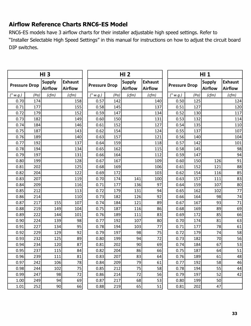
Airflow Reference Charts RNC6-ES Model
RNC6-ES models have 3 airflow charts for their installer adjustable high speed settings. Refer to “Installer Selectable High Speed Settings” in this manual for instructions on how to adjust the circuit board DIP switches.
33

1.02 254 86 63 0.89 222 62 48 0.82 204 45
1.03 257 82 60 0.90 224 59 45 0.83 207 43
1.04 259 78 57 0.91 227 56 43 0.84 209 41
1.05 262 75 54 0.92 229 53 40
1.06 264 71 51 0.93 232 51
1.07 267 68 48 0.94 234 48
1.08 269 64 45 0.95 237 46
1.09 272 61 42 0.96 239 43
1.10 274 58 0.97 242 41
1.11 277 55
1.12 279 52
1.13 282 49
1.14 284 46
1.15 287 44
1.16 289 41
1.17 292 39
Airflow Reference Charts RNC6-ES Model Continued
RNC6-E S model have 3 airflow charts for their installer adjustable high speed settings. Refer to “Installer Selectable High Speed Settings” in this manual for instructions on how to adjust the circuit board DIP switches.
34

Airflow Reference Charts RNC5-HEX-TPD/TPF ModelsRNC5-HEX-TP D and TPF models have 3 airflow charts for their installer adjustable high speed settings. Refer to “Installer Selectable High Speed Settings” in this manual for instructions on how to adjust the circuit board DIP switches.
35
Supply Airflow
Exhaust Airflow
Supply Airflow
Exhaust Airflow
Supply Airflow
Exhaust Airflow
("w.g.) (Pa) (cfm) (cfm) ("w.g.) (Pa) (cfm) (cfm) ("w.g.) (Pa) (cfm) (cfm)0.200 50 113 108 0.200 50 104 0.200 50 97 960.210 52 113 108 0.210 52 104 103 0.210 52 96 950.220 55 112 107 0.220 55 104 102 0.220 55 95 930.230 57 112 107 0.230 57 103 101 0.230 57 94 920.240 60 111 106 0.240 60 102 100 0.240 60 93 910.250 62 110 106 0.250 62 102 99 0.250 62 93 900.260 65 110 106 0.260 65 101 98 0.260 65 92 880.270 67 109 105 0.270 67 100 97 0.270 67 91 870.280 70 108 105 0.280 70 99 96 0.280 70 90 860.290 72 108 104 0.290 72 98 95 0.290 72 89 850.300 75 107 103 0.300 75 97 94 0.300 75 87 840.310 77 106 103 0.310 77 96 93 0.310 77 86 820.320 80 105 102 0.320 80 96 92 0.320 80 85 810.330 82 105 102 0.330 82 95 91 0.330 82 84 800.340 85 104 101 0.340 85 94 90 0.340 85 83 790.350 87 103 100 0.350 87 93 89 0.350 87 82 780.360 90 102 100 0.360 90 92 88 0.360 90 81 760.370 92 101 99 0.370 92 91 87 0.370 92 80 750.380 95 100 98 0.380 95 90 86 0.380 95 78 740.390 97 99 97 0.390 97 89 85 0.390 97 77 730.400 100 98 97 0.400 100 87 84 0.400 100 76 710.410 102 97 96 0.410 102 86 83 0.410 102 75 700.420 105 96 95 0.420 105 85 82 0.420 105 73 690.430 107 95 94 0.430 107 84 81 0.430 107 72 680.440 110 94 93 0.440 110 83 80 0.440 110 71 670.450 112 93 93 0.450 112 82 79 0.450 112 69 650.460 115 92 92 0.460 115 80 77 0.460 115 68 640.470 117 91 91 0.470 117 79 76 0.470 117 67 630.480 120 90 90 0.480 120 78 75 0.480 120 65 620.490 122 89 89 0.490 122 77 74 0.490 122 64 600.500 125 88 88 0.500 125 75 73 0.500 125 63 590.510 127 87 87 0.510 127 74 71 0.510 127 61 580.520 129 85 86 0.520 129 73 70 0.520 129 60 570.530 132 84 85 0.530 132 71 69 0.530 132 58 550.540 134 83 84 0.540 134 70 68 0.540 134 57 540.550 137 82 83 0.550 137 68 67 0.550 137 55 530.560 139 80 81 0.560 139 67 65 0.560 139 54 520.570 142 79 80 0.570 142 65 64 0.570 142 52 510.580 144 78 79 0.580 144 64 63 0.580 144 50 490.590 147 76 78 0.590 147 62 62 0.590 147 49 480.600 149 75 77 0.600 149 61 60 0.600 149 47 47
Hi 3Pressure
Drop
Hi 2Pressure
Drop
Hi 1Pressure
Drop
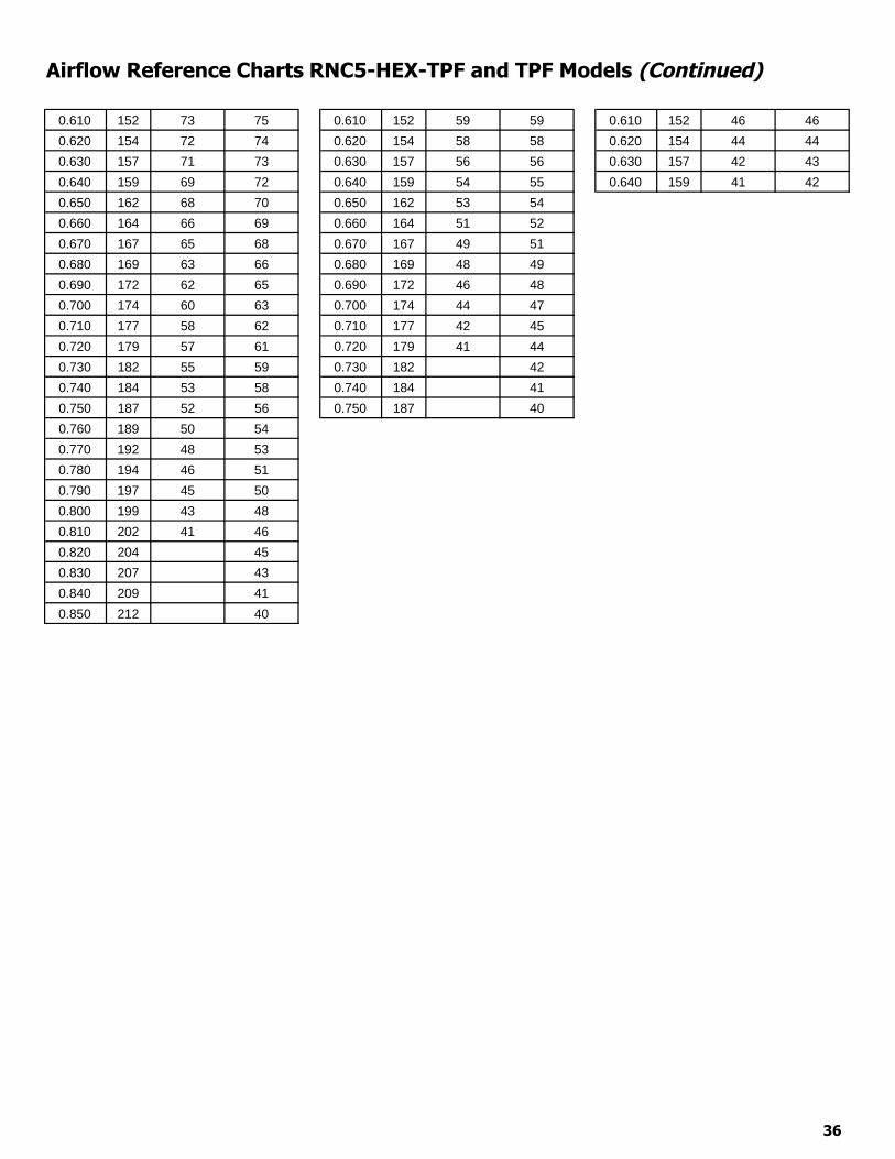
Airflow Reference Charts RNC5-HEX-TPF and TPF Models (Continued)
36
0.610 152 73 75 0.610 152 59 59 0.610 152 46 460.620 154 72 74 0.620 154 58 58 0.620 154 44 440.630 157 71 73 0.630 157 56 56 0.630 157 42 430.640 159 69 72 0.640 159 54 55 0.640 159 41 420.650 162 68 70 0.650 162 53 540.660 164 66 69 0.660 164 51 520.670 167 65 68 0.670 167 49 510.680 169 63 66 0.680 169 48 490.690 172 62 65 0.690 172 46 480.700 174 60 63 0.700 174 44 470.710 177 58 62 0.710 177 42 450.720 179 57 61 0.720 179 41 440.730 182 55 59 0.730 182 420.740 184 53 58 0.740 184 410.750 187 52 56 0.750 187 400.760 189 50 540.770 192 48 530.780 194 46 510.790 197 45 500.800 199 43 480.810 202 41 460.820 204 450.830 207 430.840 209 410.850 212 40

Airflow Reference Charts RNC155 Model155 models have 3 airflow charts for their installer adjustable high speed settings. Refer to “Installer Selectable High Speed Settings” in the installation manual for instructions on how to adjust the circuit board DIP switches. Hi 3 is the factory setting (the highest high speed). Refer to the specification sheet for high speed airflows.
37
Hi 3 Hi 2 Hi 1
Pressure Drop
Supply
Airflow
Exhaust
Airflow Pressure Drop
Supply
Airflow
Exhaust
Airflow Pressure Drop
Supply
Airflow
Exhaust
Airflow (" w.g.) (Pa) (cfm) (cfm) (" w.g.) (Pa) (cfm) (cfm) (" w.g.) (Pa) (cfm) (cfm)
0.000 0 40 0.000 0 35 0.000 0 39
0.005 1 45 0.005 1 40 0.005 1 44
0.010 3 50 0.010 3 44 0.010 3 48
0.015 4 54 0.015 4 49 0.015 4 53
0.020 5 59 0.020 5 54 0.020 5 58
0.025 6 63 0.025 6 59 0.025 6 62
0.030 8 68 0.030 8 35 63 0.030 8 67
0.035 9 72 0.035 9 38 68 0.035 9 71
0.040 10 76 0.040 10 41 72 0.040 10 76
0.045 11 81 0.045 11 43 77 0.045 11 38 81
0.050 13 39 85 0.050 13 46 81 0.050 13 42 85
0.055 14 43 89 0.055 14 49 85 0.055 14 45 90
0.060 15 46 93 0.060 15 52 90 0.060 15 49 94
0.065 16 49 97 0.065 16 54 94 0.065 16 52 99
0.070 18 53 101 0.070 18 57 98 0.070 18 55 104
0.075 19 56 105 0.075 19 60 102 0.075 19 58 108
0.080 20 59 109 0.080 20 62 106 0.080 20 61 113
0.085 21 62 113 0.085 21 65 110 0.085 21 64 117
0.090 23 65 117 0.090 23 67 114 0.090 23 67 122
0.095 24 68 120 0.095 24 70 118 0.095 24 70 127
0.100 25 71 124 0.100 25 73 122 0.100 25 73 131
0.105 26 74 128 0.105 26 75 126 0.105 26 76 136
0.110 28 76 131 0.110 28 78 129 0.110 28 79 140
0.115 29 79 135 0.115 29 80 133 0.115 29 82 145
0.120 30 81 138 0.120 30 83 137 0.120 30 84 149
0.125 31 84 141 0.125 31 85 140 0.125 31 87 154
0.130 33 86 145 0.130 33 88 144 0.130 33 89 158
0.135 34 89 148 0.135 34 90 147 0.135 34 92 163
0.140 35 91 151 0.140 35 93 150 0.140 35 94 167
0.145 36 93 154 0.145 36 95 154 0.145 36 97 172
0.150 38 96 157 0.150 38 97 157 0.150 38 99 176
0.155 39 98 160 0.155 39 100 160 0.155 39 102 181
0.160 40 100 163 0.160 40 102 163 0.160 40 104
0.165 41 102 166 0.165 41 104 166 0.165 41 107
0.170 43 104 169 0.170 43 107 169 0.170 43 109
0.175 44 106 172 0.175 44 109 172 0.175 44 111
0.180 45 108 174 0.180 45 111 175 0.180 45 113
0.185 46 110 177 0.185 46 113 178 0.185 46 116
0.190 48 112 180 0.190 48 116 181 0.190 48 118
0.195 49 114 182 0.195 49 118 184 0.195 49 120
0.200 50 116 185 0.200 50 120 186 0.200 50 123

Airflow Reference Charts RNC155 Model Continued155 models have 3 airflow charts for their installer adjustable high speed settings. Refer to “Installer Selectable High Speed Settings” in the installation manual for instructions on how to adjust the circuit board DIP switches. NOTE: Hi 3 is the factory setting (the highest high speed). Refer to the specification sheet for high speed airflows.
38
0.205 51 118 187 0.205 51 122 189 0.205 51 125
0.210 53 120 189 0.210 53 124 192 0.210 53 127
0.215 54 122 192 0.215 54 127 0.215 54 129
0.220 55 123 194 0.220 55 129 0.220 55 132
0.225 56 125 196 0.225 56 131 0.225 56 134
0.230 58 127 198 0.230 58 133 0.230 58 136
0.235 59 129 200 0.235 59 135 0.235 59 138
0.240 60 131 202 0.240 60 137 0.240 60 141
0.245 61 132 0.245 61 139 0.245 61 143
0.250 63 134 0.250 63 141 0.250 63 145
0.255 64 136 0.255 64 143 0.255 64 148
0.260 65 138 0.260 65 145 0.260 65 150
0.265 66 139 0.265 66 147 0.265 66 152
0.270 68 141 0.270 68 149 0.270 68 155
0.275 69 143 0.275 69 151 0.275 69 157
0.280 70 145 0.280 70 153 0.280 70 160
0.285 71 146 0.285 71 154 0.285 71 162
0.290 73 148 0.290 73 156 0.290 73 165
0.295 74 150 0.295 74 158 0.295 74 167
0.300 75 152 0.300 75 160 0.300 75 170
0.305 76 154 0.305 76 162 0.305 76 173
0.310 78 156 0.310 78 163 0.310 78 176
0.315 79 158 0.315 79 165 0.315 79 178
0.320 80 159 0.320 80 167 0.320 80 181
0.325 81 161 0.325 81 169
0.330 83 163 0.330 83 170
0.335 84 165 0.335 84 172
0.340 85 167 0.340 85 174
0.345 86 170 0.345 86 175
0.350 88 172 0.350 88 177
0.355 89 174 0.355 89 179
0.360 90 176 0.360 90 180
0.365 91 178 0.365 91 182
0.370 93 181 0.370 93 183
0.375 94 183 0.375 94 185
0.380 95 185 0.380 95 186
0.385 96 188 0.385 96 188
0.390 98 190 0.390 98 189
0.395 99 193 0.395 99 191
0.400 100 196 0.400 100 192
0.405 101 198
0.410 103 201
SupplyAirflow
ExhaustAirflow
SupplyAirflow
ExhaustAirflow
SupplyAirflow
ExhaustAirflow
("w.g.) Pa (cfm) (cfm) ("w.g.) Pa (cfm) (cfm) ("w.g.) Pa (cfm) (cfm)0.65 162 210 0.47 117 177 0.40 100 1530.66 164 208 0.48 120 175 0.41 102 1500.67 167 206 0.49 122 172 0.42 105 1470.68 169 204 0.50 125 169 0.43 107 1440.69 172 201 204 0.51 127 167 0.44 110 1410.70 174 199 202 0.52 130 164 177 0.45 112 138 1520.71 177 197 200 0.53 132 161 174 0.46 115 136 1480.72 179 194 197 0.54 135 159 171 0.47 117 133 1450.73 182 192 195 0.55 137 156 168 0.48 120 130 1410.74 184 190 193 0.56 140 154 165 0.49 122 128 1380.75 187 188 191 0.57 142 151 162 0.50 125 125 1350.76 189 185 188 0.58 145 149 159 0.51 127 123 1310.77 192 183 186 0.59 147 146 156 0.52 130 120 1280.78 194 181 184 0.60 150 144 153 0.53 132 117 1250.79 197 179 182 0.61 152 141 150 0.54 135 115 1220.80 199 176 179 0.62 154 139 147 0.55 137 112 1190.81 202 174 177 0.63 157 137 144 0.56 140 110 1160.82 204 172 175 0.64 159 134 141 0.57 142 108 1130.83 207 170 173 0.65 162 132 138 0.58 145 105 1100.84 209 167 171 0.66 164 129 136 0.59 147 103 1070.85 212 165 168 0.67 167 127 133 0.60 150 100 1050.86 214 163 166 0.68 169 125 130 0.61 152 98 1020.87 217 160 164 0.69 172 122 128 0.62 154 96 990.88 219 158 162 0.70 174 120 125 0.63 157 94 970.89 222 156 159 0.71 177 118 122 0.64 159 91 940.90 224 154 157 0.72 179 116 120 0.65 162 89 920.91 227 151 155 0.73 182 113 117 0.66 164 87 890.92 229 149 153 0.74 184 111 115 0.67 167 85 870.93 232 147 150 0.75 187 109 112 0.68 169 83 850.94 234 145 148 0.76 189 107 110 0.69 172 81 820.95 237 142 146 0.77 192 105 108 0.70 174 79 800.96 239 140 144 0.78 194 102 105 0.71 177 77 780.97 242 138 142 0.79 197 100 103 0.72 179 75 760.98 244 136 139 0.80 199 98 101 0.73 182 73 740.99 247 133 137 0.81 202 96 98 0.74 184 71 721.00 249 131 135 0.82 204 94 96 0.75 187 69 701.01 252 129 133 0.83 207 92 94 0.76 189 67 681.02 254 126 130 0.84 209 90 92 0.77 192 65 67
Pressure DropPressure DropPressure Drop
Hi 3 Hi 2 Hi 1
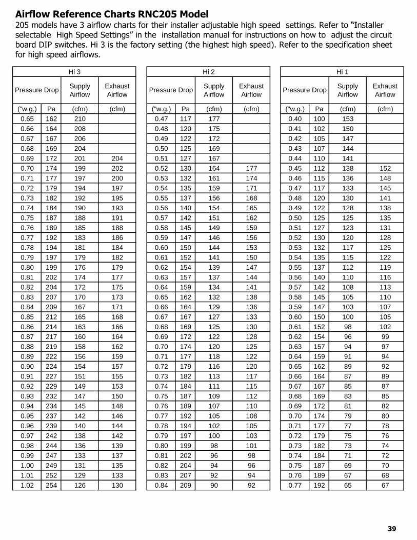
Airflow Reference Charts RNC205 Model205 models have 3 airflow charts for their installer adjustable high speed settings. Refer to “Installer“Iselectable High Speed Settings” in the installation manual for instructions on how to adjust the circuit board DIP switches. Hi 3 is the factory setting (the highest high speed). Refer to the specification sheet for high speed airflows.
39
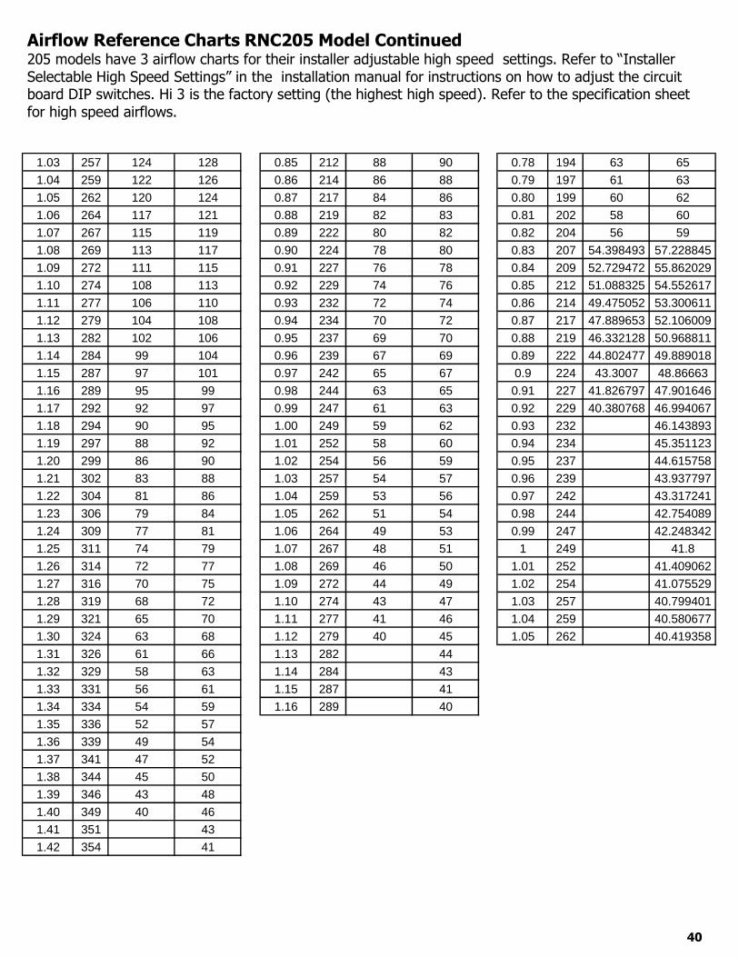
1.03 257 124 128 0.85 212 88 90 0.78 194 63 651.04 259 122 126 0.86 214 86 88 0.79 197 61 631.05 262 120 124 0.87 217 84 86 0.80 199 60 621.06 264 117 121 0.88 219 82 83 0.81 202 58 601.07 267 115 119 0.89 222 80 82 0.82 204 56 591.08 269 113 117 0.90 224 78 80 0.83 207 54.398493 57.2288451.09 272 111 115 0.91 227 76 78 0.84 209 52.729472 55.8620291.10 274 108 113 0.92 229 74 76 0.85 212 51.088325 54.5526171.11 277 106 110 0.93 232 72 74 0.86 214 49.475052 53.3006111.12 279 104 108 0.94 234 70 72 0.87 217 47.889653 52.1060091.13 282 102 106 0.95 237 69 70 0.88 219 46.332128 50.9688111.14 284 99 104 0.96 239 67 69 0.89 222 44.802477 49.8890181.15 287 97 101 0.97 242 65 67 0.9 224 43.3007 48.866631.16 289 95 99 0.98 244 63 65 0.91 227 41.826797 47.9016461.17 292 92 97 0.99 247 61 63 0.92 229 40.380768 46.9940671.18 294 90 95 1.00 249 59 62 0.93 232 46.1438931.19 297 88 92 1.01 252 58 60 0.94 234 45.3511231.20 299 86 90 1.02 254 56 59 0.95 237 44.6157581.21 302 83 88 1.03 257 54 57 0.96 239 43.9377971.22 304 81 86 1.04 259 53 56 0.97 242 43.3172411.23 306 79 84 1.05 262 51 54 0.98 244 42.7540891.24 309 77 81 1.06 264 49 53 0.99 247 42.2483421.25 311 74 79 1.07 267 48 51 1 249 41.81.26 314 72 77 1.08 269 46 50 1.01 252 41.4090621.27 316 70 75 1.09 272 44 49 1.02 254 41.0755291.28 319 68 72 1.10 274 43 47 1.03 257 40.7994011.29 321 65 70 1.11 277 41 46 1.04 259 40.5806771.30 324 63 68 1.12 279 40 45 1.05 262 40.4193581.31 326 61 66 1.13 282 441.32 329 58 63 1.14 284 431.33 331 56 61 1.15 287 411.34 334 54 59 1.16 289 401.35 336 52 571.36 339 49 541.37 341 47 521.38 344 45 501.39 346 43 481.40 349 40 461.41 351 431.42 354 41
Airflow Reference Charts RNC205 Model Continued205 models have 3 airflow charts for their installer adjustable high speed settings. Refer to “Installer Selectable High Speed Settings” in the installation manual for instructions on how to adjust the circuit board DIP switches. Hi 3 is the factory setting (the highest high speed). Refer to the specification sheet for high speed airflows.
40

MODEL 200Reading from Manometer Airflow Numbers
Water Column(inches)
Pressure(Pa)
Supply(CFM)
Exhaust(CFM)
0.100 24.9 98 910.110 27.4 102 960.120 29.9 107 1010.130 32.4 111 1070.140 34.9 115 1120.150 37.4 120 1170.160 39.9 124 1220.170 42.4 128 1270.180 44.9 133 1320.190 47.3 137 1370.200 49.8 141 1420.210 52.3 145 1470.220 54.8 149 15200.223300 5577.33 115533 1155660.240 59.8 157 1610.250 62.3 161 1660.260 64.8 165 1710.270 67.3 169 1750.280 69.8 173 1800.290 72.3 177 1840.300 74.8 181 1890.310 77.2 185 1930.320 79.7 189 1980.330 82.2 192 2020.340 84.7 196 2070.350 87.2 200 2110.360 89.7 203 215
Airflow Reference Charts RNC200 Model Door port balancing can be achieved by using these charts. Balance these Models on their factory circuit board DIP settings (Hi 3).
41

Troubleshooting SYMPTOM CAUSE SOLUTION
Poor airflows 1/4 in (6 mm) mesh on outsidehood is plugged
Filters plugged Core obstructed House grills closed or blocked Dampers are closed if installed Poor power supply at site Ductwork is restricting HRV Improper speed control setting HRV airflow improperly balanced
Clean exterior hoods or vents Remove and clean filter Remove and clean core Check and open grilles Open and adjust dampers Have electrician check supply voltage Check duct installation Increase the speed of the HRV Have contractor balance HRV
Supply air feels cold Poor location of supply grilles, theairflow may irritate the occupant
Outdoor temperature extremelycold
Locate the grilles high on the walls or underthe baseboards, install ceiling mounted diffuseor grilles so as not to directly spill the supplyair on the occupant (i.e. over a sofa)
Turn down the HRV supply speed. A smallduct heater (1 kW) could be used to temperthe supply air.
Placement of furniture or closed doors isrestricting the movement of air in the home
If supply air is ducted into furnace return, thefurnace fan may need to run continuously todistribute ventilation air comfortably
Dehumidistat in not operating
Outdoor temperature is above15oC (59oF)
Improper low voltage connection External low voltage is shortened
out by a staple or nail Check dehumidistat setting it may
be on OFF
Dehumidistat is functioning normally (see AutoDehumidistat Disable in this manual)
Check that the correct terminals have beenused
Check external wiring for a short Set the dehumidistat at the desired setting
Humidity levels are too high condensation is appearing on the windows
Dehumidistat is set too high HRV is not sized to handle a hot
tub, indoor pool etc. Lifestyle of the occupants Moisture coming into the home
from an unvented or unheatedcrawl space
Moisture is remaining in the washroom and kitchen areas
Condensation seems to form inthe spring and fall
HRV is set at too low a speed
Set dehumidistat lower Cover pools, hot tubs when they are not in
use Avoid hanging clothes to dry, storing wood
and venting clothes dryer inside. Firewoodmay have to be moved outside
Vent crawl space and place a vapor barrier onthe floor of the crawl space
Ducts from the washroom should be sized toremove moist air as effectively as possible,use of a bathroom fan for short periods willremove additional moisture
On humid days, as the seasons change, somecondensation may appear but the homes airquality will remain high with some HRV use
Increase speed of the HRVHumidity levels are too low Dehumidistat control set too low
Blower speed of HRV is too high Lifestyle of occupants HRV airflows may be improperly
balanced
Set dehumidistat higher Decrease HRV blower speed Humidity may have to be added through the
use of humidifiers Have contractor balance HRV airflows
HRV and/or ducts frosting up
HRV airflows are improperlybalanced
Malfunction of the HRV defrostsystem
Note: minimal frost build-up is expected oncores before unit initiates defrost cyclefunctions
Have HVAC contractor balance the HRV Ensure damper defrost is operating during
self-testCondensation or ice build up in insulated duct to the outside
Incomplete vapor barrier aroundinsulated duct
A hole or tear in outer ductcovering
Tape and seal all joints Tape any holes or tears made in the outer
duct covering, ensure that the vapor barrier iscompletely sealed
Excess water in the bottom of the HRV
Drain pans plugged Improper connection of HRV’s
drain lines HRV is not level Drain lines are obstructed HRV heat exchange core is not
properly installed
Look for obstructions in the drain line Look for kinks in the drain line
Excessive Vibration Dirt on fan wheels Have contractor service HRV
42


![RNC-A SERIES - Bakedeco RNC-210A_Manual.pdf · RNC-90A-R/L 2 RNC-120A-R/L 2 RNC-150A-R/L 3 RNC-180A-R/L 3 RNC-210A-R/L 4 [f] WATERPROOF COVER To prevent the entrance of water, the](https://img.pdfslide.us/doc/110x75/5e680bb313a66779ab666ae1/rnc-a-series-bakedeco-rnc-210amanualpdf-rnc-90a-rl-2-rnc-120a-rl-2-rnc-150a-rl.jpg)