Embed Size (px)
DESCRIPTION
ericsson & ALU
Citation preview
Class_MO Param_name Ericsson_ConstantArpMap systemDefaultArpQosEo YESCchFrameSynch tProcRncDl YESCchFrameSynch tProcRbsDl YESCellUpdate rrcTcuc YESChannelSwitching pendingTimeAfterTrigger YESChannelSwitching thpReportInterval YESChannelSwitching filteringCoefficient YESChannelSwitching repeatTimer YESChannelSwitching allowSwitchToCommon YESChannelSwitching inactivityTimerDch YESCpc ueDtxCycle1 YESCpc ueDtxCycle2 YESCpc macDtxCycle YESCpc ueDpcchBurst1Tti2 YESCpc ueDpcchBurst2Tti2 YESCpc ueDpcchBurst1Tti10 YESCpc ueDpcchBurst2Tti10 YESCpc inactivityThreshUeDtxCycle2Tti2 YESCpc inactivityThreshUeDtxCycle2Tti10 YESCpc ueDtxLongPreambleLength YESCpc macInactivityThresh YESCpc cqiDtxTimer YESCpc ueDrxCycle YESCpc inactivityThreshUeDrxCycle YESCpc inactivityThreshUeGrantMonTti2 YESCpc inactivityThreshUeGrantMonTti10 YESCpc ueDrxGrantMonitoring YESCpc ueDtxDrxOffsetTti2 YESCpc ueDtxDrxOffsetTti10 YESCpc enablingDelay YESCpc cpcProfileOverride YESCpmTransGapPattSeq tGSN YESCpmTransGapPattSeq tGL1 YESCpmTransGapPattSeq tGL2 YESCpmTransGapPattSeq tGPL1 YESCpmTransGapPattSeq tGPL2 YESCpmTransGapPattSeq tGPRC YESCpmTransGapPattSeq tGD YESCpmTransGapPattSeq downLinkFrameType YESCpmTransGapPattSeq nIdentifyAbort YESCpmTransGapPattSeq tReconfirmAbort YESCpmTransGapPattSeq tgcfnOffset YESDchFrameSynch tProcRncDl YESDchFrameSynch tProcRbsDl YESDchFrameSynch tProcRncUl YESDchFrameSynch tProcRbsUl YES
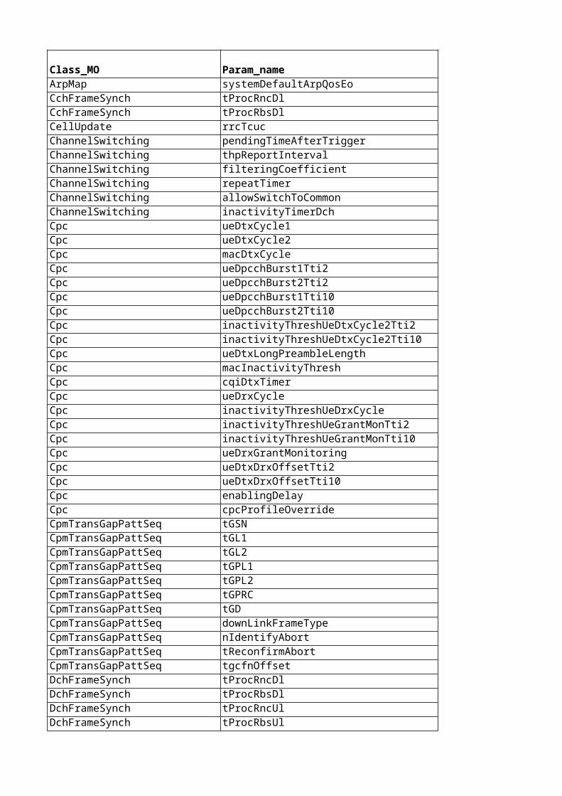
Fach fach1RateMatchingAttrDl YESFach fach2RateMatchingAttrDl YESFach sccpchPunctureLimit YESFach tfcs YESFach fach1RateMatchingAttrDlTdd YESFach fach2RateMatchingAttrDlTdd YESHandover maxBufferTime YESHandover timeRelocprep YESHandover timeRelocoverall YESHandover timeRelocsup YESHandover tCellChange YESHandover initialCellListDelay YESHandover comprModeRetryInterv YESHandover maxSohoListSubset YESHandover tsHoInIratHo YESHandover tmStopIfMeas YESHandover batonHoSupport YESIubLink tpcPattern01CountDl YESIurLink synchTimeout YESIurLink synchRetransmissions YESMbms mbmsModificationPeriodCoeff YESMbms mbmsRepetitionPeriodCoeff YESMbms nonPlSessionsMax YESMbms plSessionsMax YESMbms neighbourCellsMax YESPaging bcchModCycleLength YESPch pichMode YESPositioningServiceClass positioningServiceClassInstId YESPowerControl betaPrachControlTf0 YESPowerControl betaPrachControlTf1 YESPowerControl betaPrachDataTf0 YESPowerControl betaPrachDataTf1 YESPowerControl reportPeriodicity YESPowerControl hysteresisSiUpdate YESPowerControl maxAdjustmentStep YESPowerControl adjustmentPeriod YESPowerControl adjustmentRatio YESPowerControl codePowerPeriod YESPowerControl ulSirGuard YESPowerControl sirErrorReportHyst YESPowerControl sirEstFilter YESPowerControl sirIncreaseMask YESPowerControl blerCorrectionFactor YESPowerControl transmittedCodePowerFilter YESPowerControl rtwpFilter YESPowerControl deltaSir1 YESPowerControl deltaSirAfter1 YESPowerControl deltaSir2 YES
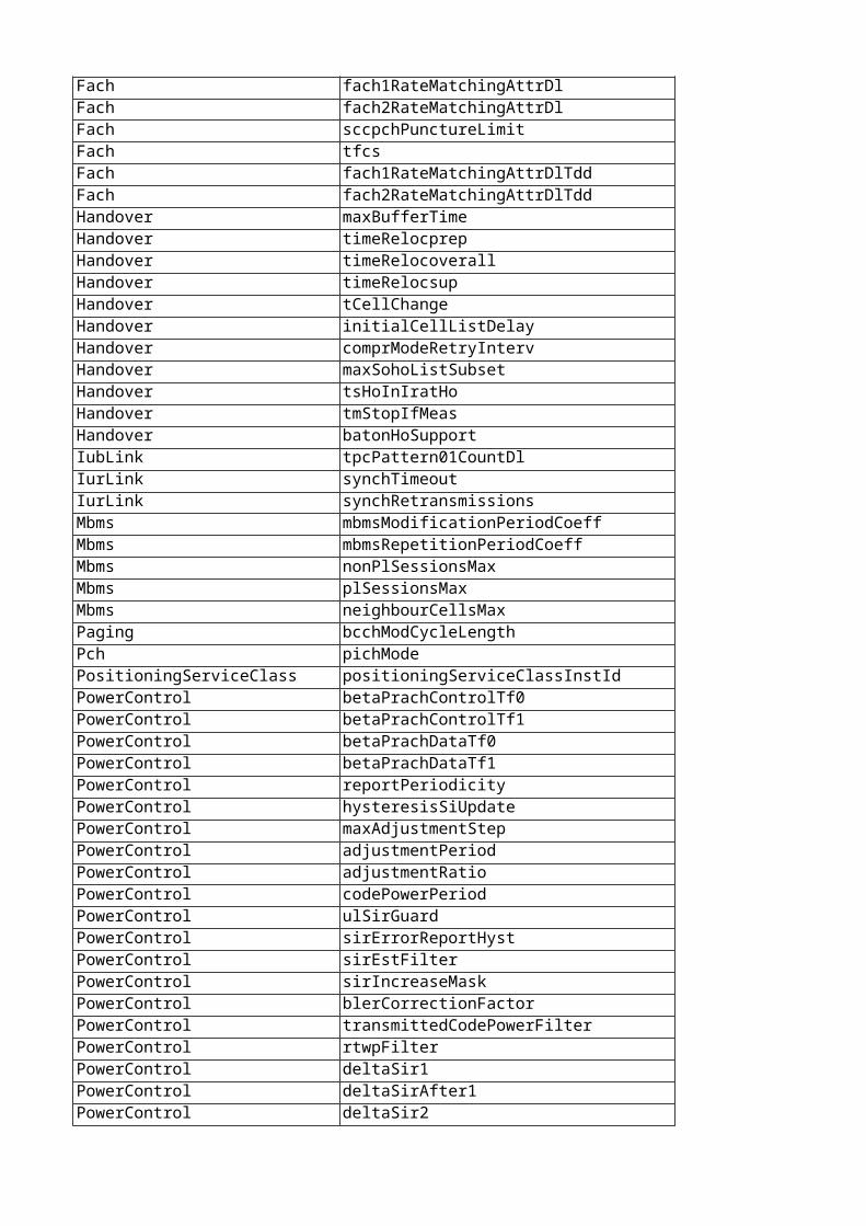
PowerControl deltaSirAfter2 YESPowerControl itp YESPowerControl rpp YESPowerControl sirErrorMode YESPowerControl cCM YESPowerControl gainFactorCLow YESPowerControl gainFactorDLow YESPowerControl gainFactorCHigh YESPowerControl gainFactorDHigh YESPowerControl gainFactorCExtraHigh YESPowerControl gainFactorDExtraHigh YESPowerControl sirIncreaseMaskTti2 YESPowerControl initDlTransPowerDefault YESPowerControl prxDpchDesDefault YESPowerControl tpcStepSize YESPowerControl pwrEstFact1 YESPowerControl pwrEstFact2 YESPowerControl pwrEstFact3 YESRabHandling eulMinHwSchRate YESRach preambleThreshold YESRncFunction gpehStorageSize YESRncFunction recordingStorageSize YESRncFunction loadSharingThreshold YESRncFunction hsCellChangeCfnOffset YESRncFunction hsMacdSwitchTimeOffset YESRncFunction eulBufferEmptyTimeThreshold YESRncFunction edchTciIntervalMin YESRncFunction hsIubDrtExtensionInterval YESRncFunction hsMissingCaSupervisionTime YESRncFunction hsMissingCaReduction YESRncFunction edchSoftCongThreshold YESRncFunction maxBlockedPreambSignatures YESRncFunction preambleThresholdIncrRachCov YESRncSystemParameters tRrcChSwitch1 YESRncSystemParameters tRrcChSwitch3 YESRncSystemParameters tNbapRnsapChSwitch4 YESRncSystemParameters tRrcEst1 YESRncSystemParameters tRrcRel1 YESRncSystemParameters tRrcRel2 YESRncSystemParameters tNbapRlSetupIub YESRncSystemParameters tRnsapRlSetupIur YESRncSystemParameters tNbapSynchRlReConfig2 YESRncSystemParameters tRnsapSynchRlReConfig1 YESRncSystemParameters tRrcRABEst YESRncSystemParameters tRrcRABRel YESRncSystemParameters tRrcActiveSetUpdate YESRncSystemParameters tNbapRlAdd YESRncSystemParameters tRnsapRlAdd YES
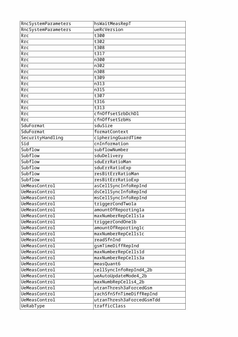
RncSystemParameters hsWaitMeasRepT YESRncSystemParameters ueRcVersion YESRrc t300 YESRrc t302 YESRrc t308 YESRrc t317 YESRrc n300 YESRrc n302 YESRrc n308 YESRrc t309 YESRrc n313 YESRrc n315 YESRrc t307 YESRrc t316 YESRrc t313 YESRrc cfnOffsetSrbDchDl YESRrc cfnOffsetSrbHs YESSduFormat sduSize YESSduFormat formatContext YESSecurityHandling cipheringGuardTime YESSid cnInformation YESSubflow subflowNumber YESSubflow sduDelivery YESSubflow sduErrRatioMan YESSubflow sduErrRatioExp YESSubflow resBitErrRatioMan YESSubflow resBitErrRatioExp YESUeMeasControl asCellSyncInfoRepInd YESUeMeasControl dsCellSyncInfoRepInd YESUeMeasControl msCellSyncInfoRepInd YESUeMeasControl triggerCondTwo1a YESUeMeasControl amountOfReporting1a YESUeMeasControl maxNumberRepCells1a YESUeMeasControl triggerCondOne1b YESUeMeasControl amountOfReporting1c YESUeMeasControl maxNumberRepCells1c YESUeMeasControl readSfnInd YESUeMeasControl gsmTimeDiffRepInd YESUeMeasControl maxNumberRepCells1d YESUeMeasControl maxNumberRepCells3a YESUeMeasControl measQuant6 YESUeMeasControl cellSyncInfoRepInd4_2b YESUeMeasControl ueAutoUpdateMode4_2b YESUeMeasControl maxNumbRepCells4_2b YESUeMeasControl utranThresh3aForcedGsm YESUeMeasControl rachSfnSfnTimeDiffRepInd YESUeMeasControl utranThresh3aForcedGsmTdd YESUeRabType trafficClass YES
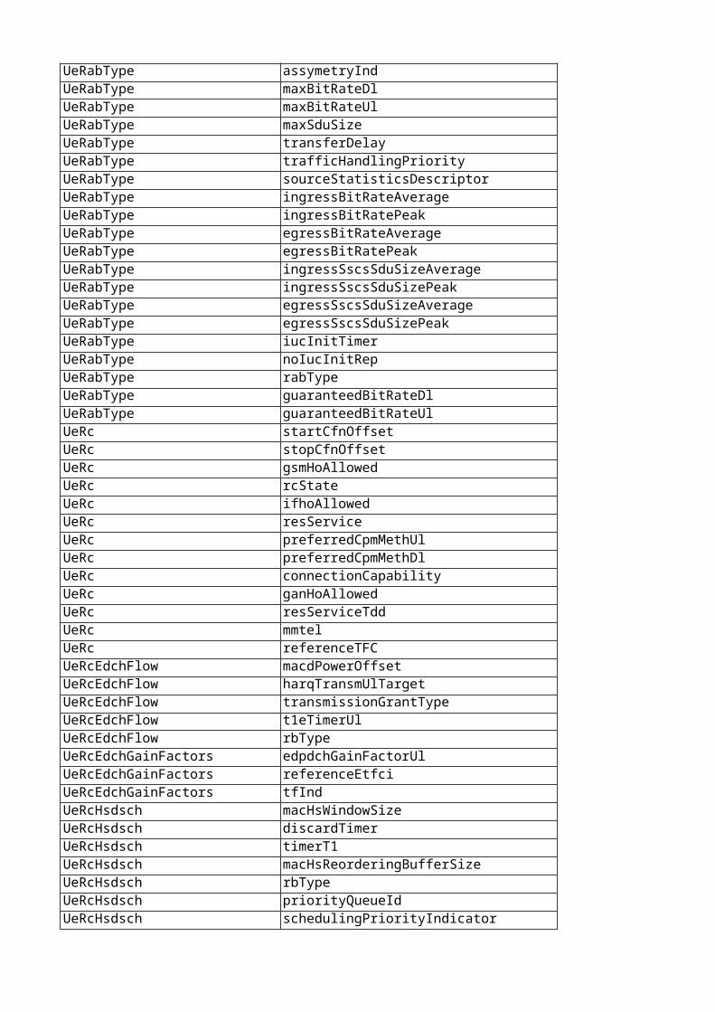
UeRabType assymetryInd YESUeRabType maxBitRateDl YESUeRabType maxBitRateUl YESUeRabType maxSduSize YESUeRabType transferDelay YESUeRabType trafficHandlingPriority YESUeRabType sourceStatisticsDescriptor YESUeRabType ingressBitRateAverage YESUeRabType ingressBitRatePeak YESUeRabType egressBitRateAverage YESUeRabType egressBitRatePeak YESUeRabType ingressSscsSduSizeAverage YESUeRabType ingressSscsSduSizePeak YESUeRabType egressSscsSduSizeAverage YESUeRabType egressSscsSduSizePeak YESUeRabType iucInitTimer YESUeRabType noIucInitRep YESUeRabType rabType YESUeRabType guaranteedBitRateDl YESUeRabType guaranteedBitRateUl YESUeRc startCfnOffset YESUeRc stopCfnOffset YESUeRc gsmHoAllowed YESUeRc rcState YESUeRc ifhoAllowed YESUeRc resService YESUeRc preferredCpmMethUl YESUeRc preferredCpmMethDl YESUeRc connectionCapability YESUeRc ganHoAllowed YESUeRc resServiceTdd YESUeRc mmtel YESUeRc referenceTFC YESUeRcEdchFlow macdPowerOffset YESUeRcEdchFlow harqTransmUlTarget YESUeRcEdchFlow transmissionGrantType YESUeRcEdchFlow t1eTimerUl YESUeRcEdchFlow rbType YESUeRcEdchGainFactors edpdchGainFactorUl YESUeRcEdchGainFactors referenceEtfci YESUeRcEdchGainFactors tfInd YESUeRcHsdsch macHsWindowSize YESUeRcHsdsch discardTimer YESUeRcHsdsch timerT1 YESUeRcHsdsch macHsReorderingBufferSize YESUeRcHsdsch rbType YESUeRcHsdsch priorityQueueId YESUeRcHsdsch schedulingPriorityIndicator YES
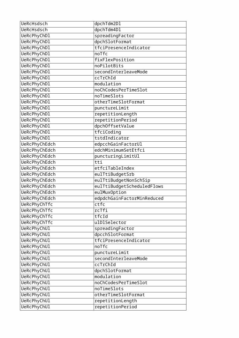
UeRcHsdsch dpchTdm2Dl YESUeRcHsdsch dpchTdm4Dl YESUeRcPhyChDl spreadingFactor YESUeRcPhyChDl dpchSlotFormat YESUeRcPhyChDl tfciPresenceIndicator YESUeRcPhyChDl noTfc YESUeRcPhyChDl fixFlexPosition YESUeRcPhyChDl noPilotBits YESUeRcPhyChDl secondInterleaveMode YESUeRcPhyChDl ccTrChId YESUeRcPhyChDl modulation YESUeRcPhyChDl noChCodesPerTimeSlot YESUeRcPhyChDl noTimeSlots YESUeRcPhyChDl otherTimeSlotFormat YESUeRcPhyChDl punctureLimit YESUeRcPhyChDl repetitionLength YESUeRcPhyChDl repetitionPeriod YESUeRcPhyChDl dpchOffsetValue YESUeRcPhyChDl tfciCoding YESUeRcPhyChDl tstdIndicator YESUeRcPhyChEdch edpcchGainFactorUl YESUeRcPhyChEdch edchMinimumSetEtfci YESUeRcPhyChEdch puncturingLimitUl YESUeRcPhyChEdch tti YESUeRcPhyChEdch etfciTableIndex YESUeRcPhyChEdch eulTtiBudgetSrb YESUeRcPhyChEdch eulTtiBudgetNonSchSip YESUeRcPhyChEdch eulTtiBudgetScheduledFlows YESUeRcPhyChEdch eulMuxOption YESUeRcPhyChEdch edpdchGainFactorMinReduced YESUeRcPhyChTfc ctfc YESUeRcPhyChTfc rcTfi YESUeRcPhyChTfc tfcId YESUeRcPhyChTfc ulDlSelector YESUeRcPhyChUl spreadingFactor YESUeRcPhyChUl dpcchSlotFormat YESUeRcPhyChUl tfciPresenceIndicator YESUeRcPhyChUl noTfc YESUeRcPhyChUl punctureLimit YESUeRcPhyChUl secondInterleaveMode YESUeRcPhyChUl ccTrChId YESUeRcPhyChUl dpchSlotFormat YESUeRcPhyChUl modulation YESUeRcPhyChUl noChCodesPerTimeSlot YESUeRcPhyChUl noTimeSlots YESUeRcPhyChUl otherTimeSlotFormat YESUeRcPhyChUl repetitionLength YESUeRcPhyChUl repetitionPeriod YES
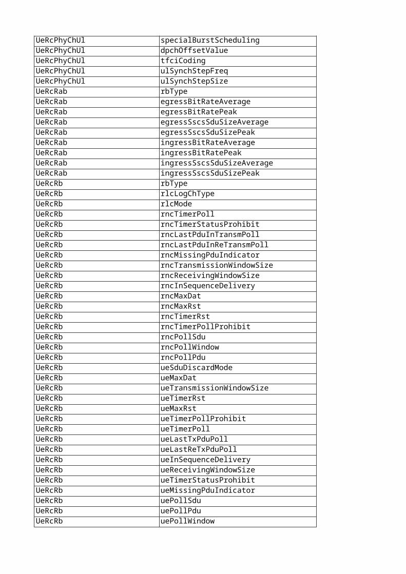
UeRcPhyChUl specialBurstScheduling YESUeRcPhyChUl dpchOffsetValue YESUeRcPhyChUl tfciCoding YESUeRcPhyChUl ulSynchStepFreq YESUeRcPhyChUl ulSynchStepSize YESUeRcRab rbType YESUeRcRab egressBitRateAverage YESUeRcRab egressBitRatePeak YESUeRcRab egressSscsSduSizeAverage YESUeRcRab egressSscsSduSizePeak YESUeRcRab ingressBitRateAverage YESUeRcRab ingressBitRatePeak YESUeRcRab ingressSscsSduSizeAverage YESUeRcRab ingressSscsSduSizePeak YESUeRcRb rbType YESUeRcRb rlcLogChType YESUeRcRb rlcMode YESUeRcRb rncTimerPoll YESUeRcRb rncTimerStatusProhibit YESUeRcRb rncLastPduInTransmPoll YESUeRcRb rncLastPduInReTransmPoll YESUeRcRb rncMissingPduIndicator YESUeRcRb rncTransmissionWindowSize YESUeRcRb rncReceivingWindowSize YESUeRcRb rncInSequenceDelivery YESUeRcRb rncMaxDat YESUeRcRb rncMaxRst YESUeRcRb rncTimerRst YESUeRcRb rncTimerPollProhibit YESUeRcRb rncPollSdu YESUeRcRb rncPollWindow YESUeRcRb rncPollPdu YESUeRcRb ueSduDiscardMode YESUeRcRb ueMaxDat YESUeRcRb ueTransmissionWindowSize YESUeRcRb ueTimerRst YESUeRcRb ueMaxRst YESUeRcRb ueTimerPollProhibit YESUeRcRb ueTimerPoll YESUeRcRb ueLastTxPduPoll YESUeRcRb ueLastReTxPduPoll YESUeRcRb ueInSequenceDelivery YESUeRcRb ueReceivingWindowSize YESUeRcRb ueTimerStatusProhibit YESUeRcRb ueMissingPduIndicator YESUeRcRb uePollSdu YESUeRcRb uePollPdu YESUeRcRb uePollWindow YES
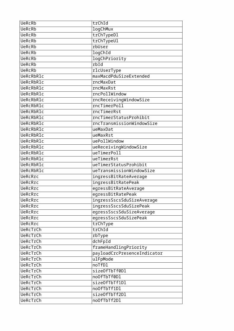
UeRcRb trChId YESUeRcRb logChMux YESUeRcRb trChTypeDl YESUeRcRb trChTypeUl YESUeRcRb rbUser YESUeRcRb logChId YESUeRcRb logChPriority YESUeRcRb rbId YESUeRcRb rlcUserType YESUeRcRbRlc maxMacdPduSizeExtended YESUeRcRbRlc rncMaxDat YESUeRcRbRlc rncMaxRst YESUeRcRbRlc rncPollWindow YESUeRcRbRlc rncReceivingWindowSize YESUeRcRbRlc rncTimerPoll YESUeRcRbRlc rncTimerRst YESUeRcRbRlc rncTimerStatusProhibit YESUeRcRbRlc rncTransmissionWindowSize YESUeRcRbRlc ueMaxDat YESUeRcRbRlc ueMaxRst YESUeRcRbRlc uePollWindow YESUeRcRbRlc ueReceivingWindowSize YESUeRcRbRlc ueTimerPoll YESUeRcRbRlc ueTimerRst YESUeRcRbRlc ueTimerStatusProhibit YESUeRcRbRlc ueTransmissionWindowSize YESUeRcRrc ingressBitRateAverage YESUeRcRrc ingressBitRatePeak YESUeRcRrc egressBitRateAverage YESUeRcRrc egressBitRatePeak YESUeRcRrc ingressSscsSduSizeAverage YESUeRcRrc ingressSscsSduSizePeak YESUeRcRrc egressSscsSduSizeAverage YESUeRcRrc egressSscsSduSizePeak YESUeRcRrc trChType YESUeRcTrCh trChId YESUeRcTrCh rbType YESUeRcTrCh dchFpId YESUeRcTrCh frameHandlingPriority YESUeRcTrCh payloadCrcPresenceIndicator YESUeRcTrCh ulFpMode YESUeRcTrCh noTfDl YESUeRcTrCh sizeOfTbTf0Dl YESUeRcTrCh noOfTbTf0Dl YESUeRcTrCh sizeOfTbTf1Dl YESUeRcTrCh noOfTbTf1Dl YESUeRcTrCh sizeOfTbTf2Dl YESUeRcTrCh noOfTbTf2Dl YES
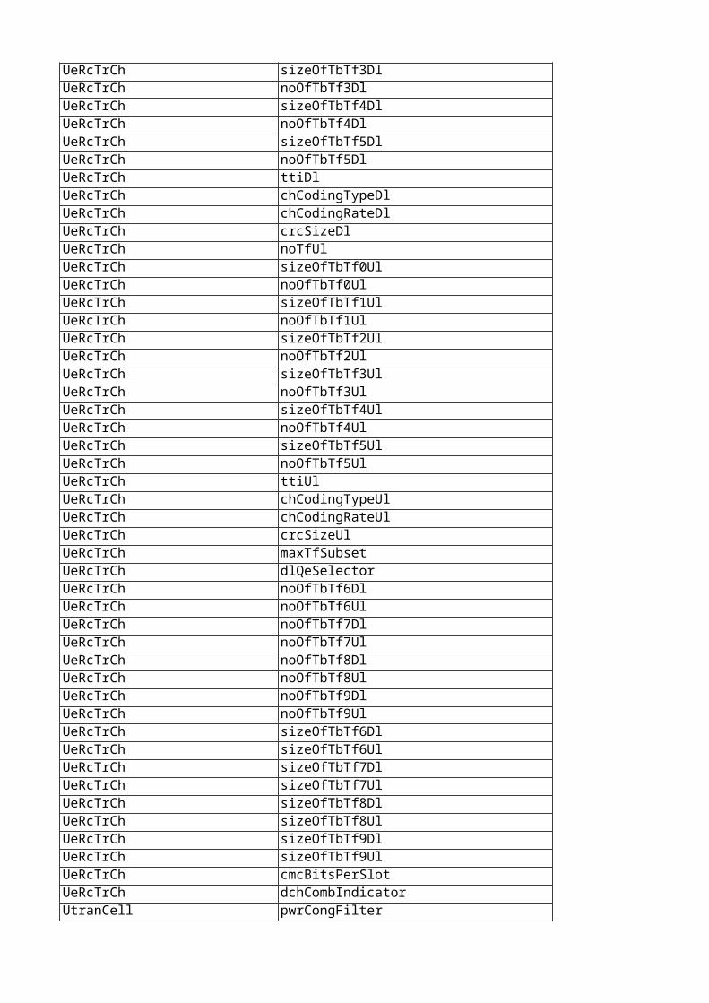
UeRcTrCh sizeOfTbTf3Dl YESUeRcTrCh noOfTbTf3Dl YESUeRcTrCh sizeOfTbTf4Dl YESUeRcTrCh noOfTbTf4Dl YESUeRcTrCh sizeOfTbTf5Dl YESUeRcTrCh noOfTbTf5Dl YESUeRcTrCh ttiDl YESUeRcTrCh chCodingTypeDl YESUeRcTrCh chCodingRateDl YESUeRcTrCh crcSizeDl YESUeRcTrCh noTfUl YESUeRcTrCh sizeOfTbTf0Ul YESUeRcTrCh noOfTbTf0Ul YESUeRcTrCh sizeOfTbTf1Ul YESUeRcTrCh noOfTbTf1Ul YESUeRcTrCh sizeOfTbTf2Ul YESUeRcTrCh noOfTbTf2Ul YESUeRcTrCh sizeOfTbTf3Ul YESUeRcTrCh noOfTbTf3Ul YESUeRcTrCh sizeOfTbTf4Ul YESUeRcTrCh noOfTbTf4Ul YESUeRcTrCh sizeOfTbTf5Ul YESUeRcTrCh noOfTbTf5Ul YESUeRcTrCh ttiUl YESUeRcTrCh chCodingTypeUl YESUeRcTrCh chCodingRateUl YESUeRcTrCh crcSizeUl YESUeRcTrCh maxTfSubset YESUeRcTrCh dlQeSelector YESUeRcTrCh noOfTbTf6Dl YESUeRcTrCh noOfTbTf6Ul YESUeRcTrCh noOfTbTf7Dl YESUeRcTrCh noOfTbTf7Ul YESUeRcTrCh noOfTbTf8Dl YESUeRcTrCh noOfTbTf8Ul YESUeRcTrCh noOfTbTf9Dl YESUeRcTrCh noOfTbTf9Ul YESUeRcTrCh sizeOfTbTf6Dl YESUeRcTrCh sizeOfTbTf6Ul YESUeRcTrCh sizeOfTbTf7Dl YESUeRcTrCh sizeOfTbTf7Ul YESUeRcTrCh sizeOfTbTf8Dl YESUeRcTrCh sizeOfTbTf8Ul YESUeRcTrCh sizeOfTbTf9Dl YESUeRcTrCh sizeOfTbTf9Ul YESUeRcTrCh cmcBitsPerSlot YESUeRcTrCh dchCombIndicator YESUtranCell pwrCongFilter YES
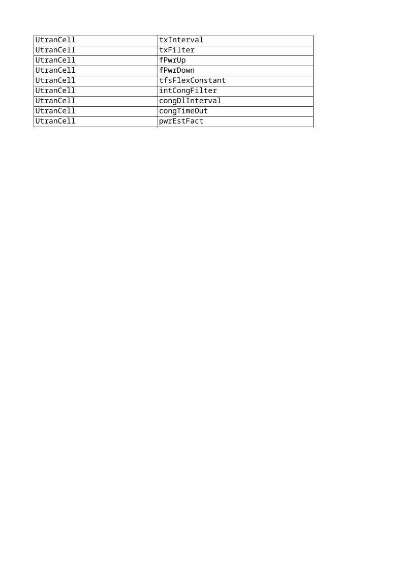
UtranCell txInterval YESUtranCell txFilter YESUtranCell fPwrUp YESUtranCell fPwrDown YESUtranCell tfsFlexConstant YESUtranCell intCongFilter YESUtranCell congDlInterval YESUtranCell congTimeOut YESUtranCell pwrEstFact YES
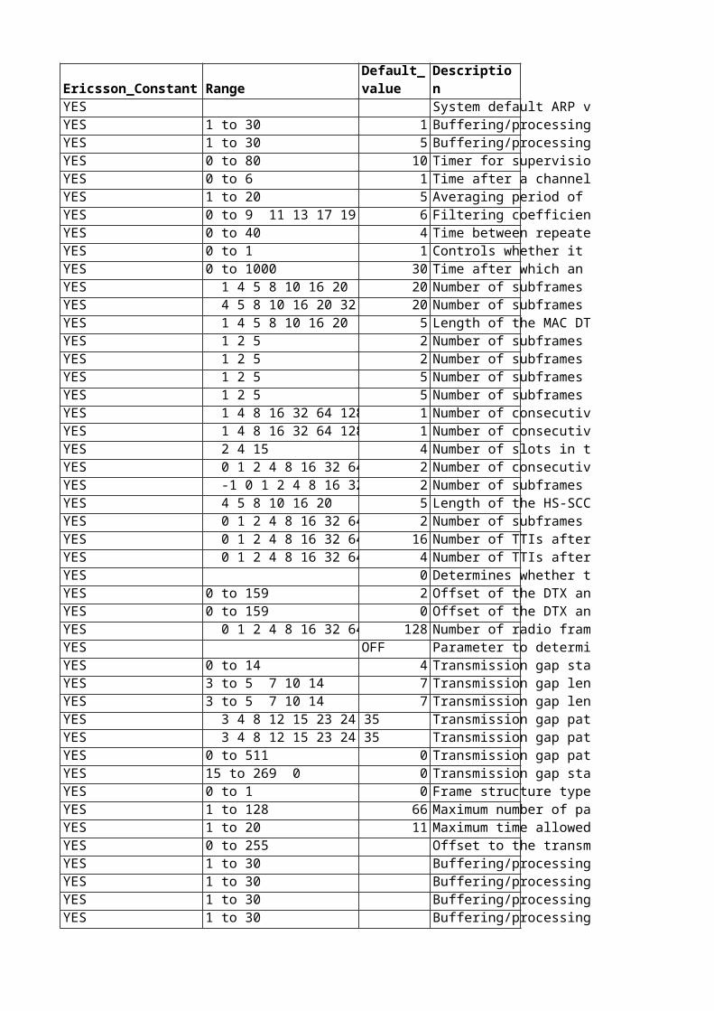
Range System default ARP values used when the ARP mapping feature is not activated through its RncFeature MO instance.This attribute may only be changed by Ericsson personnel. Dependencies:The values in this attribute are displayed in the read-only attribute systemDefaultArpQosFilter: FDD1 to 30 1 Buffering/processing time in the RNC for a FACH/PCH data frame on the downlink. Part of the Downlink Offset (DO). Should be set to the upper limit of the delay within the RNC in the transmission of each frame.The actual buffering/processing time is affected by the type of traffic frame (transport block type) as well as load, processing type, etc. If this value is set too low, frames may be lost or discarded (due to too-late arrival).This attribute may only be changed by Ericsson personnel. Unit: ms1 to 30 5 Buffering/processing time in the RBS for a FACH/PCH data frame on the downlink. Part of the Downlink Offset (DO). Should be set to the upper limit of the delay within the RBS in the transmission of each frame.The actual buffering/processing time is affected by the type of traffic frame (transport block type) as well as load, processing type, etc. If this value is set too low, frames may be lost or discarded (due to "too late" arrival).This attribute may only be changed by Ericsson personnel. Unit: ms0 to 80 10 Timer for supervision of the response to CELL UPDATE CONFIRM.This attribute may only be changed by Ericsson personnel.Unit: 0.1 s0 to 6 1 Time after a channel switch is requested, after which the next measurement report may be sent from either the UE or RNC internal buffer load measurements. Used to limit the UE and RNC buffer load reporting intensity.This attribute may only be changed by Ericsson personnel. Value mapping:0: 0.25 s1: 0.5 s2: 1 s3: 2 s4: 4 s5: 8 s6: 16 sChange takes effect: New connections1 to 20 5 Averaging period of the UL and/or DL throughput measurement.This attribute may only be changed by Ericsson personnel. Unit: 0.1 sChange takes effect: New connections0 to 9 11 13 17 19 6 Filtering coefficient of the code power measurements.This attribute may only be changed by Ericsson personnel. Change takes effect: New connections0 to 40 4 Time between repeated requests to downswitch a downlink radio bearer on DCH with bad coverage to a lower DCH rate.This attribute may only be changed by Ericsson personnel. Special values.0: the repeat timer not in use, meaning that a downswitch request will not be repeatedValue mapping:1: 50 ms...4: 200 ms...40: 2000msUnit: 50 msChange takes effect: New connections0 to 1 1 Controls whether it is allowed to switch the radio connection from a dedicated transport channel to a common transport channel (RACH/FACH) during channel switching in case of radio bearer inactivity.This attribute may only be changed by Ericsson personnel. Value mapping:0: Transition to common channel (RACH/FACH) is not allowed1: Transition to common channel (RACH/FACH) is allowedChange takes effect: New connections0 to 1000 30 Time after which an IU RELEASE REQUEST message is sent to the core network, for UEs that only use one or two signaling connections and no RABs in state CELL_DCH.This attribute may only be changed by Ericsson personnel. Special values:0: do not release (no need to start measurements or algorithm)Unit: sChange takes effect: New connections 1 4 5 8 10 16 20 20 Number of subframes in the uplink DPCCH pattern in DTX cycle 1.This attribute may only be changed by Ericsson personnel.Change takes effect: New connectionFilter: FDD 4 5 8 10 16 20 32 40 6 20 Number of subframes in the uplink DPCCH pattern in DTX cycle 2.This attribute may only be changed by Ericsson personnel.Change takes effect: New connectionFilter: FDD 1 4 5 8 10 16 20 5 Length of the MAC DTX cycle.This attribute may only be changed by Ericsson personnel.Change takes effect: New connectionFilter: FDD 1 2 5 2 Number of subframes in the uplink DPCCH burst in DTX cycle 1 for EUL 2ms TTI.This attribute may only be changed by Ericsson personnel.Change takes effect: New connectionFilter: FDD 1 2 5 2 Number of subframes in the uplink DPCCH burst in DTX cycle 2 for EUL 2ms TTI.This attribute may only be changed by Ericsson personnel.Change takes effect: New connectionFilter: FDD 1 2 5 5 Number of subframes in the uplink DPCCH burst in DTX cycle 1 for EUL 10ms TTI.This attribute may only be changed by Ericsson personnel.Change takes effect: New connectionFilter: FDD 1 2 5 5 Number of subframes in the uplink DPCCH burst in DTX cycle 2 for EUL 10ms TTI.This attribute may only be changed by Ericsson personnel.Change takes effect: New connectionFilter: FDD 1 4 8 16 32 64 128 256 1 Number of consecutive E-DCH TTIs without an E-DCH transmission, after which the UE shall immediately move from DTX cycle 1 to DTX cycle 2, for EUL 2ms TTI .This attribute may only be changed by Ericsson personnel.Change takes effect: New connectionFilter: FDD 1 4 8 16 32 64 128 256 1 Number of consecutive E-DCH TTIs without an E-DCH transmission, after which the UE shall immediately move from DTX cycle 1 to DTX cycle 2, for EUL 10ms TTI.This attribute may only be changed by Ericsson personnel.Change takes effect: New connectionFilter: FDD 2 4 15 4 Number of slots in the long preamble associated with DTX cycle 2 Note, when this parameter is set to 2, RNC excludes the IE "UE DTX long preamble length" from the RRC message containing the IE DTX-DRX information.This attribute may only be changed by Ericsson personnel.Change takes effect: New connectionFilter: FDD 0 1 2 4 8 16 32 64 128 2 Number of consecutive E-DCH TTIs without an E-DCH transmission, after which the UE E-DCH transmissions are restricted to the MAC DTX pattern. The UE E-DCH transmissions are never restricted to the MAC DTX pattern when it is set to 0 (=infinity).This attribute may only be changed by Ericsson personnel.Change takes effect: New connectionFilter: FDD -1 0 1 2 4 8 16 32 64 1 2 Number of subframes after an HS-DSCH reception during which the CQI reports have higher priority than the DTX pattern The CQI reports always have higher priority than the DTX pattern when it is set to -1 (=infinity). This attribute may only be changed by Ericsson personnel.Change takes effect: New connectionFilter: FDD 4 5 8 10 16 20 5 Length of the HS-SCCH reception pattern in subframes.This attribute may only be changed by Ericsson personnel.Change takes effect: New connectionFilter: FDD 0 1 2 4 8 16 32 64 128 2 Number of subframes after an HS-SCCH reception or after the first slot of an HS-PDSCH reception during which the UE shall monitor the HS-SCCHs in the UE's HS-SCCH set continuously.This attribute may only be changed by Ericsson personnel.Change takes effect: New connectionFilter: FDD 0 1 2 4 8 16 32 64 128 16 Number of TTIs after an E-DCH transmission during which the UE shall monitor the E-AGCH transmissions from the serving E-DCH cell and the E-RGCH from cells in the serving E-DCH radio link set, for EUL 2ms TTI.This attribute may only be changed by Ericsson personnel.Change takes effect: New connectionFilter: FDD 0 1 2 4 8 16 32 64 128 4 Number of TTIs after an E-DCH transmission during which the UE shall monitor the E-AGCH transmissions from the serving E-DCH cell and the E-RGCH from cells in the serving E-DCH radio link set, for EUL 10ms TTI.This attribute may only be changed by Ericsson personnel.Change takes effect: New connectionFilter: FDD 0 Determines whether the UE is required to monitor the E-AGCH and the E-RGCH when the subframe (2msTTI) or frame (10ms TTI) overlaps with the start of the DRX reception pattern.This attribute may only be changed by Ericsson personnel.Change takes effect: New connectionFilter: FDD0 to 159 2 Offset of the DTX and DRX cycles compared to the CFN for E-DCH 2ms TTI.This attribute may only be changed by Ericsson personnel.Change takes effect: New connectionFilter: FDD0 to 159 0 Offset of the DTX and DRX cycles compared to the CFN for E-DCH 10ms TTI.This attribute may only be changed by Ericsson personnel.Change takes effect: New connectionFilter: FDD 0 1 2 4 8 16 32 64 128 128 Number of radio frames during which the UE shall send DPCCH continuously after (re)configuration with CPC activated.This attribute may only be changed by Ericsson personnel.Change takes effect: New connectionFilter: FDD OFF Parameter to determine whether the pre-defined hardcoded parameter set(profile) is used or not to configure the CPC connections. If it is set to "OFF", the CPC connections are configured with a pre-defined hardcoded parameter set(CPC profile). If ON, the static configuration associated with the CPC profile is overridden by the values set for the parameters of the MO CPC.This attribute may only be changed by Ericsson personnel.Change takes effect: New connectionFilter: FDD0 to 14 4 Transmission gap starting slot number. A transmission gap pattern begins in a radio frame, containing at least one transmission gap slot. TGSN is the slot number of the first transmission gap slot within the first radio frame of the transmission gap pattern. This attribute may only be changed by Ericsson personnel. Change takes effect: Next configuration of the transmission gap pattern sequence in UE, DRNC or RBS.3 to 5 7 10 14 7 Transmission gap length 1. Number of slots in the first transmission gap within the transmission gap pattern. This attribute may only be changed by Ericsson personnel. Value mapping:Possible values for GSM carrier RSSI Measurement are 3, 4, 5, 7, 10, 14.Possible values for Initial BSIC identification are 7, 10, 14.Possible values for BSIC re-confirmation are 7, 10, 14.Possible values for Inter Frequency measurements are 7, 10, 14.Since the value ranges are different for each pattern sequence, the system will not check the range. It is the responsibility of the user (Ericsson personnel) to check the range when configuring the parameter. Change takes effect: Next configuration of the transmission gap pattern sequence in UE, DRNC or RBS.3 to 5 7 10 14 7 Transmission gap length 2. Number of slots in the second transmission gap within the transmission gap pattern. This attribute may only be changed by Ericsson personnel. Dependencies:If this parameter is not explicitly set by higher layers, then tGL2 = tGL1. Value mapping:Possible values for GSM carrier RSSI Measurement are 3, 4, 5, 7, 10, 14.Possible values for Initial BSIC identification are 7, 10, 14.Possible values for BSIC re-confirmation are 7, 10, 14.Possible values for Inter Frequency measurements are 7, 10, 14.Since the value ranges are different for each pattern sequence, the system will not check the range. It is the responsibility of the user (Ericsson personnel) to check the range when configuring the parameter. Change takes effect: Next configuration of the transmission gap pattern sequence in UE, DRNC or RBS. 3 4 8 12 15 23 24 35 Transmission gap pattern length 1. Number of frames in transmission gap pattern 1.This attribute may only be changed by Ericsson personnel. Special values:Initial value (set by system) for GSM carrier RSSI Measurement ("CpmTransGapPattSeq=1") is 8.Initial value (set by system) for Initial BSIC identification ("CpmTransGapPattSeq=2") is 8.Initial value (set by system) for BSIC re-confirmation ("CpmTransGapPattSeq=3") is 8.Initial value (set by system) for Inter Frequency measurements ("CpmTransGapPattSeq=4") is 4.Value mapping:Possible value for GSM carrier RSSI Measurement is 8.Possible values for Initial BSIC identification are 3, 4, 8, 12, 24.Possible values for BSIC re-confirmation are 3, 4, 8, 12, 15, 23, 24.Possible values for Inter Frequency measurements are 3, 4, 8, 12, 24, 35.Since the value ranges are different for each pattern sequence, the system will only check that the value is within the full range defined for the parameter. There is no check that a value for a specific sequence is within the range for that sequence. For example, the value 23 will be accepted for Initial BSIC identification. It is the responsibility of the user (Ericsson personnel) to check that the value for a specific sequence is within the range of that sequence when configuring the parameter. Change takes effect: Next configuration of the transmission gap pattern sequence in UE, DRNC or RBS. 3 4 8 12 15 23 24 35 Transmission gap pattern length 2. Numer of frames in transmission gap pattern 2.This attribute may only be changed by Ericsson personnel. Special values:Initial value (set by system) for GSM carrier RSSI Measurement ("CpmTransGapPattSeq=1") is 8.Initial value (set by system) for Initial BSIC identification ("CpmTransGapPattSeq=2") is 8.Initial value (set by system) for BSIC re-confirmation ("CpmTransGapPattSeq=3") is 8.Initial value (set by system) for Inter Frequency measurements ("CpmTransGapPattSeq=4") is 4.Dependencies:It is up to the user (Ericsson personnel) to make sure tGLP1 = tGPL2 for subsequent changes during operation. There is no check in the code for this.Value mapping:Possible value for GSM carrier RSSI Measurement is 8.Possible values for Initial BSIC identification are 3, 4, 8, 12, 24.Possible values for BSIC re-confirmation are 3, 4, 8, 12, 15, 23, 24.Possible values for Inter Frequency measurements are 3, 4, 8, 12, 24, 35.Since the value ranges are different for each pattern sequence, the system will only check that the value is within the full range defined for the parameter. There is no check that a value for a specific sequence is within the range for that sequence. For example, the value 23 will be accepted for Initial BSIC identification. It is the responsibility of the user (Ericsson personnel) to check that the value for a specific sequence is within the range of that sequence when configuring the parameter. Change takes effect: Next configuration of the transmission gap pattern sequence in UE, DRNC or RBS.0 to 511 0 Transmission gap pattern repetition count. Number of transmission gap patterns within the transmission gap pattern sequence. This attribute may only be changed by Ericsson personnel. Special values:0 means infinity. Change takes effect: Next configuration of the transmission gap pattern sequence in UE, DRNC or RBS.15 to 269 0 0 Transmission gap start distance. Number of slots between the starting slots of two consecutive transmission gaps within a transmission gap pattern. If this parameter is not set by higher layers, then there is only one transmission gap in the transmission gap pattern. If there is only one transmission gap in the transmission gap pattern, this parameter shall be set to 0.This attribute may only be changed by Ericsson personnel. Special values:0 means undefinedChange takes effect: Next configuration of the transmission gap pattern sequence in UE, DRNC or RBS.0 to 1 0 Frame structure type used in downlink compressed mode control. This attribute may only be changed by Ericsson personnel. Value mapping:0 = 'A'1 = 'B' Change takes effect: Next configuration of the transmission gap pattern sequence in UE, DRNC or RBS.1 to 128 66 Maximum number of pattern repeats that the UE shall use to attempt to decode the unknown BSIC of a GSM cell in the initial BSIC identification procedure.This attribute may only be changed by Ericsson personnel. Change takes effect: Next configuration of the transmission gap pattern sequence in UE, DRNC or RBS.1 to 20 11 Maximum time allowed for the re-confirmation of the BSIC of a GSM cell in the BSIC re-confirmation procedure.This attribute may only be changed by Ericsson personnel. Value mapping:1: 0.5 s2: 1.0 s3: 1.5 s...11: 5.5 s...20: 10.0 sUnit: 0.5 sChange takes effect: Next configuration of the transmission gap pattern sequence in UE, DRNC or RBS.0 to 255 Offset to the transmission gap connection frame number, for the pattern sequence when starting CPM.TGCFN = running CFN + startCFNoffset + TGCFNoffsetThis attribute may only be changed by Ericsson personnel. Special values:Initial value (set by system) for GSM carrier RSSI measurement ("CpmTransGapPattSeq=1") is 0.Initial value (set by system) for Initial BSIC identification ("CpmTransGapPattSeq=2") is 2.Initial value (set by system) for BSIC reconfirmation ("CpmTransGapPattSeq=3") is 6.Initial value (set by system) for Inter Frequency measurements ("CpmTransGapPattSeq=4") is 0.Change takes effect: Next configuration of the transmission gap pattern sequence in UE, DRNC or RBS.1 to 30 Buffering/processing time for a downlink DCH data frame in RNC.This attribute may only be changed by Ericsson personnel. Unit: ms1 to 30 Buffering/processing time for a downlink DCH data frame in RBS.This attribute may only be changed by Ericsson personnel. Unit: ms1 to 30 Buffering/processing time for an uplink DCH data frame in RNC.This attribute may only be changed by Ericsson personnel. Dependencies:It is recommended to set tProcRncUl + toAWEUl + toAEUl <= 640 [ms] It is recommended to set toAWSUl <= toAEUlUnit: ms1 to 30 Buffering/processing time for an uplink DCH data frame in RBS.This attribute may only be changed by Ericsson personnel. Unit: ms
Default_value
Parameter_Description
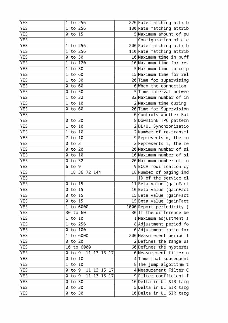
1 to 256 220 Rate matching attribute in downlink for Fach1.The Fach1 is used for logical channels BCCH, CCCH and DCCH, control signaling.This attribute may only be changed by Ericsson personnel. Disturbances:Changing this attribute may affect ongoing traffic.Filter: FDD1 to 256 130 Rate matching attribute in downlink for Fach2.The Fach2 is used for logical channel DTCH, traffic signaling.This attribute may only be changed by Ericsson personnel. Disturbances:Changing this attribute may affect ongoing traffic.Filter: FDD0 to 15 5 Maximum amount of puncturing for common channels.Value mapping:0: 40 %1: 44 %2: 48 %...15: 100 %This attribute may only be changed by Ericsson personnel.Dependencies:Before changing this attribute, check if tfcs needs to be changed as well. If so, lock the parent UtranCell manually before changing both.Disturbances:Changing this attribute may affect ongoing traffic.Unit: 4 %Filter: TDDReplaces: tdSccpchPunctureLimit Configuration of elements used to build the Transport Format Combination Set (TFCS) for PCH, FACH1 and FACH2.This attribute may only be changed by Ericsson personnel.Disturbances:Changing this attribute may affect ongoing traffic.Filter: TDDReplaces: tdTfcs1 to 256 200 Rate matching attribute in the downlink for the first FACH. The first FACH is used for logical channels BCCH, CCCH and DCCH, for control signaling.This attribute may only be changed by Ericsson personnel. Disturbances:Changing this attribute may affect ongoing traffic.Dependencies:Before changing this attribute, check if tfcs needs to be changed as well. If so, lock the parent UtranCell manually before changing both. Filter: TDD1 to 256 110 Rate matching attribute in the downlink for the second FACH. The second FACH is used for logical channel DTCH, for traffic signaling.This attribute may only be changed by Ericsson personnel. Disturbances:Changing this attribute may affect ongoing traffic.Dependencies:Before changing this attribute, check if tfcs needs to be changed as well. If so, lock the parent UtranCell manually before changing both.Filter: TDD0 to 50 10 Maximum time in buffer for a buffered report. This attribute may only be changed by Ericsson personnel. Value mapping:0: 0 s1: 0.2 s2: 0.4 s3: 0.6 s4: 0.8 s5: 1.0 s...50: 10 sUnit: 0.2 sChange takes effect: Ongoing connections (next switch to CELL_DCH)1 to 120 10 Maximum time for resource allocation in the target system. This attribute may only be changed by Ericsson personnel. Unit: sChange takes effect: New connections1 to 30 5 Maximum time to complete a handover.This attribute may only be changed by Ericsson personnel. Unit: sChange takes effect: New connections1 to 60 15 Maximum time for relocation in the target RNC. This attribute may only be changed by Ericsson personnel. Unit: sChange takes effect: New connections1 to 30 20 Time for supervising the "move" from UTRAN to GSM.Once the cell change order from UTRAN has been sent, the system expects to receive an Iu release command or Cell change failure from UTRAN within this amount of time.This attribute may only be changed by Ericsson personnel. Unit: sChange takes effect: New connections0 to 60 0 When the connection is set up for the first time, Measurement handler function will wait this predetermined time before it sends the first cell list to the UE. This extra delay will decrease the risk for the UE not to get the initial cell list , since initially it is busy to get synchronized to UTRAN.This attribute may only be changed by Ericsson personnel. Unit: sChange takes effect: Ongoing connections0 to 50 5 Time interval between trials to initiate compressed mode. This attribute may only be changed by Ericsson personnel. Special values:0 means no retry. Value mapping:0: 0.0 s1: 0.2 s2: 0.4 s3: 0.6 s4: 0.8 s5: 1.0 s...50: 10 sUnit: 0.2 sChange takes effect: Ongoing connections (next switch to CELL_DCH)Filter: FDD1 to 32 32 Maximum number of intra-frequency cells that the UE shall measure on. This attribute may only be changed by Ericsson personnel. Change takes effect: Ongoing connections1 to 10 2 Maximum time during which soft or softer handover may be triggered during IRAT-HO execution.This attribute may only be changed by Ericsson personnel. Value mapping:1: 0.5 s2: 1.0 s...10: 5.0 sUnit: 0.5 sChange takes effect: New connections0 to 60 20 Time for Supervision for measurements started due to Inter-frequency Load based handover.Unit: SecondsChange takes effect: Next soft congestionThis attribute may only be changed by Ericsson personnel. Filter: FDD 0 Controls whether Baton Handover is supported for Intra-RNC Hard Handover.This attribute may only be changed by Ericsson personnel. Filter: TDDReplaces: tdBatonHoSupport0 to 30 8 Downlink TPC pattern transmitted for the first RLS, until uplink initial synchronization is achieved. This parameter is used for the NBAP cell setup message.This attribute may only be changed by Ericsson personnel. Dependencies: Changing this attribute may affect ongoing traffic.1 to 10 2 DL/UL Synchronization control frame timeout value.This attribute may only be changed by Ericsson personnel. Unit: 100 ms1 to 10 2 Number of re-transmissions when sending a DL/UL Synchronization control frame.This attribute may only be changed by Ericsson personnel. 7 to 10 9 Represents m, the modification period coefficient. The actual modification period (MP), in number of frames, equals 2^m.m >= k, where k = max[cnDrxCycleLengthPs, cnDrxCycleLengthCs, utranDrxCycleLength] To allow the UE to measure, when applicable, on another frequency when reading MCCH there has to be some gaps in the MCCH transmission (the MP shall not be fully utilized). Note: The UE and SGSN can negotiate the value of the cnDrxCycleLengthPs. This case can not be handled by the system. This attribute may only be changed by Ericsson personnel.Change takes effect: At MbmsCch lock/unlock and at system restart0 to 3 2 Represents r, the repetition period coefficient. The number of repetitions per modification period equals 2^r while the actual repetition period, in number of frames, equals [2^m DIV 2^r], where m is the modification period coefficient.[2^m DIV 2^r] >= nrOfRrcFrames, where nrOfRrcFrames defines the number of frames the MCCH information requires in each Repetition Period. (Note: nrOfRrcFrames is not a parameter but only a definition in the above equation.)This attribute may only be changed by Ericsson personnel.Change takes effect: At MbmsCch lock/unlock and at system restart0 to 20 20 Maximum number of simultaneous ongoing MBMS sessions in one non-PL cell. The MCCH FACH with TTI 20 ms for S-CCPCH has maximum user data rate 7.6 kbps.The values of the mbmsModificationPeriodCoeff (m) and mbmsRepetitionPeriodCoeff (r) have dependencies to the number of frames that can be scheduled per Repetition Period on MCCH with the data rate 7.6 kbps. Parameters nonPlSessionsMax, plSessionsMax and neighbourCellsMax put limits on number of frames to be scheduled in a worst case scenario.It must be considered when changing any of the above parameters that the number of frames to be scheduled on MCCH for RRC messages does not exceed the number of frames that can be scheduled per Repetition Period on MCCH.This attribute may only be changed by Ericsson personnel.Change takes effect: At MbmsCch lock/unlock and at system restartFilter: FDD0 to 10 10 Maximum number of simultaneous ongoing MBMS sessions in one PL cell. The MCCH FACH with TTI 20 ms for S-CCPCH has maximum user data rate 7.6 kbps.The values of the mbmsModificationPeriodCoeff (m) and mbmsRepetitionPeriodCoeff (r) have dependencies to the number of frames that can be scheduled per Repetition Period on MCCH with the data rate 7.6 kbps. Parameters nonPlSessionsMax, plSessionsMax and neighbourCellsMax put limits on number of frames to be scheduled in a worst case scenario.It must be considered when changing any of the above parameters that the number of frames to be scheduled on MCCH for RRC messages does not exceed the number of frames that can be scheduled per Repetition Period on MCCH.This attribute may only be changed by Ericsson personnel.Change takes effect: At MbmsCch lock/unlock and at system restart0 to 32 20 Maximum number of intra-frequency neighboring cells for which information is sent on MCCH. The MCCH FACH with TTI 20 ms for S-CCPCH has maximum user data rate 7.6 kbps.The values of the mbmsModificationPeriodCoeff (m) and mbmsRepetitionPeriodCoeff (r) have dependencies to the number of frames that can be scheduled per Repetition Period on MCCH with the data rate 7.6 kbps. Parameters nonPlSessionsMax, plSessionsMax and neighbourCellsMax put limits on number of frames to be scheduled in a worst case scenario.It must be considered when changing any of the above parameters that the number of frames to be scheduled on MCCH for RRC messages does not exceed the number of frames that can be scheduled per Repetition Period on MCCH.This attribute may only be changed by Ericsson personnel.Change takes effect: At MbmsCch lock/unlock and at system restart6 to 9 9 BCCH modification cycle length coefficient (k). The cycle length is calculated as the k'th potential of 2, where k = 6,..,9. The BCCH modification information element should be transmitted in every frame within a defined interval. This interval will be within a specific cycle interval similarly defined as DRX cycle length.Special values:Initially set by the system to 9 (corresponds to cycle length 5,120 s).This attribute may only be changed by Ericsson personnel. 18 36 72 144 18 Number of paging indications per frame in the PICH.This attribute may only be changed by Ericsson personnel. Disturbances:Changing this attribute may affect ongoing traffic.Filter: FDD ID of the service class.This attribute may only be changed by Ericsson personnel. Filter: FDD0 to 15 11 Beta value (gainFactor) for RACH control part, TFC 0.This attribute may only be changed by Ericsson personnel. Disturbances:Changing this attribute may affect ongoing traffic.Change takes effect: New connectionsFilter: FDD0 to 15 10 Beta value (gainFactor) for RACH control part, TFC 1.This attribute may only be changed by Ericsson personnel. Disturbances:Changing this attribute may affect ongoing traffic.Change takes effect: New connectionsFilter: FDD0 to 15 15 Beta value (gainFactor) for RACH data part, TFC 0.This attribute may only be changed by Ericsson personnel. Disturbances:Changing this attribute may affect ongoing traffic.Change takes effect: New connections0 to 15 15 Beta value (gainFactor) for RACH data part, TFC 1.This attribute may only be changed by Ericsson personnel. Disturbances:Changing this attribute may affect ongoing traffic.Change takes effect: New connectionsFilter: FDD1 to 6000 1000 Report periodicity (RTWP period) for RBS common measurements.This attribute may only be changed by Ericsson personnel. Disturbances:Changing this attribute may affect ongoing traffic.Unit: 10 msChange takes effect: New connections30 to 60 30 If the difference between reported power measurement and the power value transmitted in System Information is larger than this hysteresis in one cell, an update of system information is initiated in that cell.This attribute may only be changed by Ericsson personnel. Value mapping:30: 3.0 dB31: 3.1 dB...60: 6.0 dBUnit: 0.1 dBFilter: FDD1 to 10 1 Maximum adjustment step for downlink power balancing.This parameter is signaled over NBAP with the values [1..10] slots, where 1 corresponds to an allowed change of the downlink power (due to downlink power balancing) of at most 1 dB every 1 slot. 10 corresponds to an allowed change of the downlink power of at most 1 dB every 10 slots.maxAdjustmentStep = 1 corresponds to a limit on rate of change of 1 dB/slot.maxAdjustmentStep = 10 corresponds to a limit on rate of change of 0.1 dB/slot.This attribute may only be changed by Ericsson personnel. Change takes effect: New connectionsFilter: FDD1 to 256 8 Adjustment period for downlink power balancing.This attribute may only be changed by Ericsson personnel. Change takes effect: New connectionsFilter: FDD0 to 100 0 Adjustment ratio for downlink power balancing.This attribute may only be changed by Ericsson personnel. Change takes effect: New connectionsFilter: FDD1 to 6000 200 Measurement period for downlink power balancing.This attribute may only be changed by Ericsson personnel. Unit: 10 msChange takes effect: New connectionsFilter: FDD0 to 20 2 Defines the range used when determine when a SIR error measurement report shall be sent from the RBS to RNC.This attribute may only be changed by Ericsson personnel. Unit: dBChange takes effect: New connectionsFilter: FDD10 to 6000 60 Defines the hysteresis used to determine when a SIR error measurement report shall be sent from the RBS to RNC.This attribute may only be changed by Ericsson personnel. Resolution: 10Unit: msChange takes effect: New connectionsFilter: FDD0 to 9 11 13 15 17 19 0 Measurement filtering coefficient used to determine when a SIR error measurement report shall be sent from the RBS to RNC.This attribute may only be changed by Ericsson personnel. Change takes effect: New connectionsFilter: FDD0 to 10 4 Time that subsequent "SIR target up" commands are ignored after a successful "SIR target up" command, for 10 ms TTI users.This attribute may only be changed by Ericsson personnel. Unit: radio frame (10 ms)Change takes effect: New connections1 to 10 8 The jump algorithm typically gives a result that is slightly biased towards increased BLER. This parameter is used to compensate for this bias.This attribute may only be changed by Ericsson personnel. Value mapping: 1: 0,1 2: 0,2...10: 1,0Change takes effect: New connections0 to 9 11 13 15 17 19 4 Measurement Filter Coefficient for Transmitted Code Power measurement used for downlink power balancing.This attribute may only be changed by Ericsson personnel. Dependencies: Changing this attribute may affect traffic.Change takes effect: New connectionsFilter: FDD0 to 9 11 13 15 17 19 9 Filter coefficient for received total wideband power measurement. This attribute may only be changed by Ericsson personnel. Change takes effect: New connections0 to 30 10 Delta in UL SIR target value during the frame containing the start of the first transmission gap in the transmission gap pattern. This attribute may only be changed by Ericsson personnel. Unit: 0.1 dBChange takes effect: New connectionsFilter: FDD0 to 30 5 Delta in UL SIR target value during the frame after the frame containing the start of the first transmission gap in the transmission gap pattern.This attribute may only be changed by Ericsson personnel. Unit: 0.1 dBChange takes effect: New connectionsFilter: FDD0 to 30 10 Delta in UL SIR target value during the frame containing the start of the second transmission gap in the transmission gap pattern. This attribute may only be changed by Ericsson personnel. Unit: 0.1 dBChange takes effect: New connectionsFilter: FDD
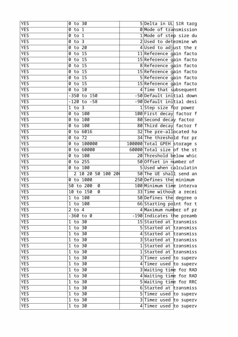
0 to 30 5 Delta in UL SIR target value during the frame after the frame containing the start of the second transmission gap in the transmission gap pattern.This attribute may only be changed by Ericsson personnel. Unit: 0.1 dBChange takes effect: New connectionsFilter: FDD0 to 1 0 Mode of transmission power of the uplink DPCCH at the first slot after transmission gap. This attribute may only be changed by Ericsson personnel. Change takes effect: New connectionsFilter: FDD0 to 1 1 Mode of step size during recovery period. This attribute may only be changed by Ericsson personnel. Change takes effect: New connections0 to 3 2 Used to determine which SIR error measurements shall be initiated.This attribute may only be changed by Ericsson personnel. Value mapping:0: None1: Event E2: Event F3: Both (1&2)Filter: FDD0 to 20 4 Used to adjust the reference power for users in compressed mode during DL power balancingThis attribute may only be changed by Ericsson personnel. Value mapping:0: 0.0 dB...4: 2.0 dB...20: 10.0 dBUnit: 0.5 dBFilter: FDD0 to 15 11 Reference gain factor (generic beta value) for the uplink DPCCH part of RABs (or SRB) with a minimum spreading factor >= 32. 'Low' refers to low data transmission capability due to high spreading factor.Used by Power Control.This attribute may only be changed by Ericsson personnel. Dependencies:Note that either gainFactorCLow or gainFactorDLow must be equal to 15.Filter: FDD0 to 15 15 Reference gain factor (generic beta value) for the uplink DPDCH part of RABs (or SRB) with a minimum spreading factor >= 32. 'Low' refers to low data transmission capability due to high spreading factor.Used by Power Control.This attribute may only be changed by Ericsson personnel. Dependencies:Note that either gainFactorCLow or gainFactorDLow must be equal to 15.0 to 15 8 Reference gain factor (generic beta value) for the uplink DPCCH part of RABs (or SRB) with a minimum spreading factor in the range 8 < SF <= 16. 'High' refers to high data transmission capability due to low spreading factor.Used by Power Control.This attribute may only be changed by Ericsson personnel. Dependencies:Note that either gainFactorCHigh or gainFactorDHigh must be equal to 15.Filter: FDD0 to 15 15 Reference gain factor (generic beta value) for the uplink DPDCH part of RABs (or SRB) with a minimum spreading factor in the range 8 < SF <= 16. 'High' refers to high data transmission capability due to low spreading factor.Used by Power Control.This attribute may only be changed by Ericsson personnel. Dependencies:Note that either gainFactorCHigh or gainFactorDHigh must be equal to 15.0 to 15 5 Reference gain factor (generic beta value) for the uplink DPCCH part of RABs (or SRB) with a minimum spreading factor <= 8. 'Extra high' refers to extra high data transmission capability due to very low spreading factor. Used by Power Control.This attribute may only be changed by Ericsson personnel. Dependencies:gainFactorCExtraHigh or gainFactorDExtraHigh must be equal to 150 to 15 15 Reference gain factor (generic beta value) for the uplink DPDCH part of RABs (or SRB) with a minimum spreading factor <= 8. 'Extra high' refers to extra high data transmission capability due to very low spreading factor. Used by Power Control.This attribute may only be changed by Ericsson personnel. Dependencies:gainFactorCExtraHigh or gainFactorDExtraHigh must be equal to 15Filter: FDD0 to 10 4 Time that subsequent "SIR target up" commands are ignored after a successful "SIR target up" command, for 2 ms TTI users.This attribute may only be changed by Ericsson personnel. Unit: radio frame (10 ms)Filter: FDD-350 to 150 -50 Default initial downlink transmission power, used when the PCCPCH RSCP or downlink time slot ISCP is not received from the measurement report. Expressed relative to the value of UtranCell::pccpchPower.This attribute may only be changed by Ericsson personnel.Unit: 0.1 dBFilter: TDDReplaces: tdDefaultInitDlTransPower-120 to -58 -90 Default initial desired received uplink DPCH power value, used when the uplink time slot ISCP is not received from the measurement report. In the RRC CONNECTION SETUP message, the value of this attribute is used for the parameter ul-TargetSIR.This attribute may only be changed by Ericsson personnel.Unit: dBmFilter: TDDReplaces: tdDefaultPrxDpchDes1 to 3 1 Step size for power adjustment.This attribute may only be changed by Ericsson personnel.Unit: dBFilter: TDDReplaces: tdTddTpcStepSize0 to 100 100 First decay factor for the downlink power estimation decay used by Admission Control.This attribute may only be changed by Ericsson personnel. Unit: %Filter: TDD0 to 100 80 Second decay factor for the downlink power estimation decay used by Admission Control.This attribute may only be changed by Ericsson personnel. Unit: %Filter: TDD0 to 100 80 Third decay factor for the downlink power estimation decay used by Admission Control.This attribute may only be changed by Ericsson personnel. Unit: %Filter: TDD0 to 6016 32 The pre-allocated hardware rate for scheduled data for E-DCH users in the RBS. Needed for RBS hardware consumption calculations in RNC. The calculation is performed in the same way for 2 ms and 10 ms TTI, with this constant as input, but the values shall then be rounded up differently depending on the used TTI. This attribute may only be changed by Ericsson personnel. Dependencies: The same constant is defined in the RBS for the scheduler. These constants should be set to the same value. Unit: kbps (1000 bits per second)Resolution: 32Change takes effect: Ongoing connectionsFilter: FDD0 to 72 34 The threshold for preamble detection, relative to the interference level. This attribute may only be changed by Ericsson personnel. Value mapping: 0: -36.0 dB 1: -35.5 dB...34: -19.0 dB...72: 0.0 dBDisturbances:Changing this attribute may affect ongoing traffic.Unit: 0.5 dBFilter: FDD0 to 100000 100000 Total GPEH storage size available on the O&M MP and each Module MP.When gpehStorageSize is exceeded, the GPEH function will remove the oldest GPEH file(s) from the persistent storage to make space for a new file, and GPEH recording will continue.This attribute may only be changed by Ericsson personnel.Dependencies: The size of the GPEH file may never exceed the available GPEH storage size on each MP (gpehStorageSize >= gpehFileSize).Unit: kB (1000 bytes)Change takes affect: Next ROP0 to 60000 60000 Total size of the storage space available for PM Recording ROP files on the O&M MP.When recordingStorageSize is reached, the PM Recording function will remove the oldest recording file and continue. If the recordingStorageSize is completely used by a single recording file, the PM Recording function will stop the recording until the next ROP begins.This attribute may only be changed by Ericsson personnel. Dependencies: The file sizes for UETR and CTR recordings may never exceed the available recording storage size on the central O&M MP: recordingStorageSize >= ctrFileSize, recordingStorageSize >= uetrFileSizeUnit: kB (1000 bytes)Change takes effect: Next ROP0 to 100 20 Threshold below which RRC redirections for inter-frequency load sharing will be inhibited. Defined in terms of the difference in available resources between the source cell and the target cell. This attribute may only be changed by Ericsson personnel. Unit: %Change takes effect: Immediately0 to 255 50 Offset in number of frames calculated from the activation time at serving HS-DSCH Cell Change.This attribute may only be changed by Ericsson personnel. Dependencies:hsCellChangeCfnOffset >= hsMacdSwitchTimeOffsetFilter: FDD0 to 100 5 Used when calculating the time for the switch-over of the HS MAC-D flow from Source Cell to Target Cell, at Serving HS-DSCH Cell Change.This attribute may only be changed by Ericsson personnel. Dependencies:hsMacdSwitchTimeOffset <= hsCellChangeCfnOffsetUnit: frame 2 10 20 50 100 200 50 50 The UE shall send an unhappy bit if it takes the UE more than this time to empty its buffer with the current serving grant.This attribute may only be changed by Ericsson personnel.Unit: ms0 to 1000 250 Defines the minimum interval between two consecutive TNL CONGESTION INDICATION control frames, belonging to one flow controlled EUL flow, which are sent towards RBS. The interval is valid per flow controlled flow, regardless of which type of TCI that are sent, e.g. with code 2 or 3. This attribute may only be changed by Ericsson personnel. Unit: msResolution: 5050 to 200 0 100 Minimum time interval between two HS-DSCH Data Frames with a DRT Extension. The purpose is to not send DRT Extensions too often. When the parameter is set to zero, no DRT Extensions are sent (the feature is turned OFF). This attribute may only be changed by Ericsson personnel. Unit: msResolution: 10Change takes effect: New connections10 to 150 0 33 Time without a received CAPACITY ALLOCATION (CA) control frame, for this PQF, that results in a reduced HSDPA bit rate. The reason for checking the presence of these CAPACITY ALLOCATION control frames in RNC is that a CA shall be received at least every one second time interval (more often or once per second). If this doesn't happen, it is likely that a CA is dropped over the transport network. Further on, if several CA control frames are dropped, not received in RNC, it could mean that the best effort type of transport network is congested. This attribute may only be changed by Ericsson personnel. Special values:0 defines that CA presence supervision is turned off.Unit: 0.1 sChange takes effect: New connections1 to 100 50 Defines the degree of bit rate reduction due to missing CAPACITY ALLOCATION control frames.Example: New bit rate = Old bit rate * (1- hsMissingCaReduction/100). This attribute may only be changed by Ericsson personnel. Unit: %Change takes effect: New connections1 to 100 66 Starting point for the soft congestion detection. This point is the shortest dynamic delay that can be detected as soft congestion, expressed as percentage of edchDataFrameDelayThresholdThis attribute may only be changed by Ericsson personnel. Unit: %2 to 4 4 Maximum number of preamble signatures that can be blocked in a cell.This attribute may only be changed by Ericsson personnel. Change takes effect: ImmediatelyFilter: FDD-360 to 0 -190 Indicates the preamble threshold to be used when the feature Increased RACH Coverage is active.This attribute may only be changed by Ericsson personnel. Value mapping:-360: -36.0 dB-355: -35.5 dB... -190: -19.0 dB... -5: -0.5 dB0: 0 dBUnit: 0.1 dBResolution: 5Change takes effect: ImmediatelyFilter: FDD1 to 30 15 Started at transmission of RRC: RADIO BEARER RECONFIGURATION. Stopped at reception of RRC: RADIO BEARER RECONFIGURATION COMPLETE.Unit: sThis attribute may only be changed by Ericsson personnel. 1 to 30 5 Started at transmission of RRC: TRANSPORT CHANNEL RECONFIGURATION or RADIO BEARER RECONFIGURATION. Stopped at reception of RRC: TRANSPORT CHANNEL RECONFIGURATION COMPLETE or RADIO BEARER RECONFIGURATION COMPLETE.Unit: sThis attribute may only be changed by Ericsson personnel. 1 to 30 4 Started at transmission of DEDICATED MEASUREMENT INITIATION REQUEST. Stopped at reception of DEDICATED MEASUREMENT INITIATION RESPONSE.Unit: sThis attribute may only be changed by Ericsson personnel. 1 to 30 3 Started at transmission of RRC CONNECTION SETUP to UE. Stopped at reception of RRC CONNECTION SETUP COMPLETE.Unit: sThis attribute may only be changed by Ericsson personnel. 1 to 30 1 Started at transmission of RRC CONNECTION RELEASE to UE in state CELL_DCH. Stopped at reception of RRC CONNECTION RELEASE COMPLETE.Unit: sThis attribute may only be changed by Ericsson personnel. 1 to 30 1 Started at transmission of RRC CONNECTION RELEASE to UE in state CELL_FACH. Stopped at reception of RRC CONNECTION RELEASE COMPLETE.Unit: sThis attribute may only be changed by Ericsson personnel. 1 to 30 3 Timer used to supervise the NBAP Radio Link Setup procedure. Started at transmission of NBAP RADIO LINK SETUP REQUEST. Stopped at reception of NBAP RADIO LINK SETUP RESPONSE.Unit: sThis attribute may only be changed by Ericsson personnel. 1 to 30 4 Timer used to supervise the RNSAP Radio Link Setup procedure. Started at transmission of RNSAP RADIO LINK SETUP REQUEST. Stopped at reception of RNSAP RADIO LINK SETUP RESPONSE.Unit: sThis attribute may only be changed by Ericsson personnel. 1 to 30 3 Waiting time for RADIO LINK RECONFIGURATION READY (Iub).Unit: sThis attribute may only be changed by Ericsson personnel. 1 to 30 4 Waiting time for RADIO LINK RECONFIGURATION READY (Iur).Unit: sThis attribute may only be changed by Ericsson personnel. 1 to 30 5 Waiting time for RRC RESPONSE.Unit: sThis attribute may only be changed by Ericsson personnel. 1 to 30 6 Started at transmission of RRC: RADIO BEARER RELEASE or RADIO BEARER RECONFIGURATION. Stopped at reception of RRC: RADIO BEARER RELEASE COMPLETE or RADIO BEARER RECONFIGURATION COMPLETE.Unit: sThis attribute may only be changed by Ericsson personnel. 1 to 30 5 Timer used to supervise the RRC Active Set Update procedure. Started at transmission of RRC ACTIVE SET UPDATE REQUEST. Stopped at reception of RRC ACTIVE SET UPDATE COMPLETE or RRC ACTIVE SET UPDATE FAILURE.Unit: sThis attribute may only be changed by Ericsson personnel. 1 to 30 3 Timer used to supervise the NBAP Radio Link Addition procedure. Started at transmission of NBAP RADIO LINK ADDITION REQUEST. Stopped at reception of NBAP RADIO LINK ADDITION RESPONSE or NBAP RADIO LINK ADDITION FAILURE or NBAP ERROR INDICATION.Unit: sThis attribute may only be changed by Ericsson personnel. 1 to 30 4 Timer used to supervise the RNSAP Radio Link Addition procedure. Started at transmission of RNSAP RADIO LINK ADDITION REQUEST. Stopped at reception of RNSAP RADIO LINK ADDITION RESPONSE or RNSAP RADIO LINK ADDITION FAILURE or RNSAP ERROR INDICATION.Unit: sThis attribute may only be changed by Ericsson personnel.
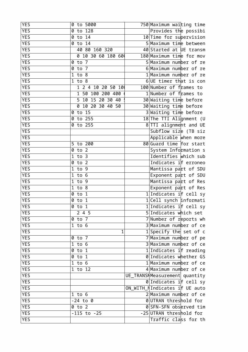
0 to 5000 750 Maximum waiting time for a Measurement Report from the UE.Unit: msResolution: 250This attribute may only be changed by Ericsson personnel. 0 to 128 Provides the possibility to record script version run on the node. The value is not used by the RNC.This attribute may only be changed by Ericsson personnel. 0 to 14 10 Time for supervision of RRC Connection Setup.Used by the UE.This attribute may only be changed by Ericsson personnel. Value mapping:0: 100 ms1: 200 ms2: 400 ms3: 600 ms4: 800 ms5: 1000 ms6: 1200 ms7: 1400 ms8: 1600 ms9: 1800 ms10: 2000 ms11: 3000 ms12: 4000 ms13: 6000 ms14: 8000 msChange takes effect: New connections0 to 14 5 Maximum time between UE transmission of Cell Update message and UE reception of the Cell Update Confirm message. If not received, the UE sends a new Cell Update. This attribute may only be changed by Ericsson personnel. 0: 100 ms1: 200 ms2: 400 ms3: 600 ms4: 800 ms5: 1000 ms6: 1200 ms7: 1400 ms8: 1600 ms9: 1800 ms10: 2000 ms11: 3000 ms12: 4000 ms13: 6000 ms14: 8000 ms 40 80 160 320 40 Started at UE transmission of the RRC Connection Release Complete message. Set in SIB 1.This attribute may only be changed by Ericsson personnel. Change takes effect: New connections 0 10 30 60 180 600 12 180 Maximum time for moving from CELL_FACH to idle mode if "out of service area". Used by Rel-4 and earlier UEs. Rel-5 and later UEs will ignore the value of this attribute.This attribute may only be changed by Ericsson personnel. Unit: s0 to 7 5 Maximum number of retransmissions of RRC Connection Request.Used by the UE.This attribute may only be changed by Ericsson personnel. Change takes effect: New connections0 to 7 6 Maximum number of retransmissions of Cell Update.Used by the UE.This attribute may only be changed by Ericsson personnel. 1 to 8 1 Maximum number of retransmissions of the RRC connection release complete message.Used by the UE. This attribute may only be changed by Ericsson personnel. Change takes effect: New connections1 to 8 6 UE timer that is controlled by UTRAN and sent to the UE in system information. This attribute may only be changed by Ericsson personnel. Change takes effect: New connections 1 2 4 10 20 50 100 200 100 Number of frames to be considered for out-of-sync detection (UE in DCH).This attribute may only be changed by Ericsson personnel. 1 50 100 200 400 600 1 Number of frames to be considered for in-sync detection (UE in DCH)This attribute may only be changed by Ericsson personnel. Dependencies:Must not be set longer than t313, assuming 1 frame = 10 ms. 5 10 15 20 30 40 50 30 Waiting time before moving to idle (UE in PCH or FACH)This attribute may only be changed by Ericsson personnel. Unit: s 0 10 20 30 40 50 30 Waiting time before starting T317 (UE in PCH)This attribute may only be changed by Ericsson personnel. Unit: s0 to 15 3 Waiting time before "RL Failure" (UE in DCH).This attribute may only be changed by Ericsson personnel. Special values:0 indicates that the t313 is not in use.Dependencies:Must be set longer than n315, assuming 1 frame = 10 ms.Unit: s0 to 255 18 The TTI Alignment (UL and 2*DL) and UE Processing delay in number of radio frames added to the activation time (i.e. the CFN) calculated by the RNC using SRB on DCH-DL. This system constant can be calculated in the following way: cfnOffsetSrbDchDl = 2*TTI_Alignment_DL + TTI_Alignment_UL + UE_Processing_UL_and_DL Default value is calculated as: 2*4+4+6=18 radio frames Unit: 10 msChange takes effect: At next synchronized reconfiguration of the connection This attribute may only be changed by Ericsson personnel. 0 to 255 8 TTI alignment and UE Processing delay in number of radio frames added to the activation time (i.e. the CFN) calculated by the RNC using SRB on HS. This system constant can be calculated in the following way: cfnOffsetSrbHs = TTI_Alignment_DL+ TTI_Alignment_UL+ UE_Processing_UL_and_DL Default value is calculated as: 2+10+60ms=72ms=8 radio framesUnit: 10 msChange takes effect: At next synchronized reconfiguration of the connection.This attribute may only be changed by Ericsson personnel. Subflow size (TB size).This attribute may only be changed by Ericsson personnel. Unit: bit Applicable when more than one SDU Format exists per subflow and more than one subflow exists for one rabType. It is used to create a subflow combination with the correct sduSize parameters e.g. SID + an AMR rate.This attribute may only be changed by Ericsson personnel. 5 to 200 80 Guard time for start of ciphering in RLC-TM.This attribute may only be changed by Ericsson personnel. Unit: frames0 to 2 System Information should be distributed about these CNs. This attribute may only be changed by Ericsson personnel. Value mapping:0: PS only 1: CS only 2: PS and CS1 to 3 Identifies which subflow this MO instance relates to. This attribute may only be changed by Ericsson personnel. 0 to 2 Indicates if erroneous SDUs shall be delivered or not.This attribute may only be changed by Ericsson personnel. Value mapping:0: Erroneous SDUs are delivered1: Erroneous SDUs are not delivered2: No check if SDUs are erroneous1 to 9 Mantissa part of SDU Error Ratio.This attribute may only be changed by Ericsson personnel. 1 to 6 Exponent part of SDU Error Ratio.This attribute may only be changed by Ericsson personnel. 1 to 9 Mantissa part of Residual Bit Error Ratio.This attribute may only be changed by Ericsson personnel. 1 to 8 Exponent part of Residual Bit Error Ratio.This attribute may only be changed by Ericsson personnel. 0 to 1 1 Indicates if cell synchronization information shall be reported for cells in the active set. This attribute may only be changed by Ericsson personnel. Value mapping:0: False1: TrueChange takes effect: Ongoing connections (next switch to CELL_DCH)Filter: FDD0 to 1 1 Cell synch information report indicator. Indicates if cell synchronization information shall be reported for cells in the detected set. This attribute may only be changed by Ericsson personnel. Value mapping:0: False1: TrueChange takes effect: Ongoing connections (next switch to CELL_DCH)Filter: FDD0 to 1 1 Indicates if cell synchronization information shall be reported for the cells in the monitored set. This attribute may only be changed by Ericsson personnel. Value mapping:0: False1: TrueChange takes effect: Ongoing connections (next switch to CELL_DCH)Filter: FDD 2 4 5 5 Indicates which set of the cells shall be used in event 1a reporting evaluation. This attribute may only be changed by Ericsson personnel. Value mapping:2 : Monitored set cells4 : Detected set cells5 : Detected set cells and monitored set cellsChange takes effect: Ongoing connections (next switch to CELL_DCH)Filter: FDD0 to 7 7 Number of reports when UE has reverted to event-triggered periodical reporting due to 'cell addition failure', for event type 1a.Used by UE functions for intra-frequency measurement reporting (in CELL_DCH). This attribute may only be changed by Ericsson personnel. Value mapping:0: 11: 22: 4...6: 647: infinityChange takes effect: Ongoing connections (next switch to CELL_DCH)Filter: FDD1 to 6 3 Maximum number of cells included in the report for event 1a. This attribute may only be changed by Ericsson personnel. Value mapping:1 : Virtual/Active set cells + 12 : Virtual/Active set cells + 23 : Virtual/Active set cells + 34 : Virtual/Active set cells + 45 : Virtual/Active set cells + 56 : Virtual/Active set cells + 6Change takes effect: Ongoing connections (next switch to CELL_DCH)Filter: FDD
1 1 Specify the set of cells that shall be used in event 1b reporting evaluation. This attribute may only be changed by Ericsson personnel. Value mapping:1: Active set cellsChange takes effect: Ongoing connections (next switch to CELL_DCH)Filter: FDD0 to 7 7 Maximum number of periodic reports at event-triggered periodic reporting for event 1c. This attribute may only be changed by Ericsson personnel. Value mapping:0: 11: 22: 4...6: 647: infinityChange takes effect: Ongoing connections (next switch to CELL_DCH)Filter: FDD1 to 6 3 Maximum number of cells included in the report for event 1c. This attribute may only be changed by Ericsson personnel. Value mapping:1 : Virtual/Active set cells + 12 : Virtual/Active set cells + 23 : Virtual/Active set cells + 34 : Virtual/Active set cells + 45 : Virtual/Active set cells + 56 : Virtual/Active set cells + 6Change takes effect: Ongoing connections (next switch to CELL_DCH)Filter: FDD0 to 1 1 Indicates if reading of SFN is required for the target cell. This attribute may only be changed by Ericsson personnel. Value mapping:0 : False1 : TrueChange takes effect: Ongoing connections (next switch to CELL_DCH)0 to 1 0 Indicates whether GSM observed time difference shall be reported for GSM cells. This attribute may only be changed by Ericsson personnel. Value mapping:0 : False1 : TrueChange takes effect: Ongoing connections (next time that inter-RAT measurements are started)1 to 6 1 Maximum number of cells included in the report for event 1d. This attribute may only be changed by Ericsson personnel. Value mapping:1: Virtual/Active set cells + 12: Virtual/Active set cells + 23: Virtual/Active set cells + 34: Virtual/Active set cells + 45: Virtual/Active set cells + 56: Virtual/Active set cells + 6Change takes effect: Ongoing connections (next switch to CELL_DCH)Filter: FDD1 to 12 4 Maximum number of cells included in the report for event 3a.This attribute may only be changed by Ericsson personnel. Filter: FDD UE_TRANS Measurement quantity for UL connection quality reporting evaluation, for event 6a and 6b.This attribute may only be changed by Ericsson personnel. Change takes effect: Ongoing connections (next switch to CELL_DCH)Filter: FDD 0 Indicates if cell synchronization information shall be reported for cells in the Virtual Active Set(s), for measurement 4 event 2b.This attribute may only be changed by Ericsson personnel. Change takes effect: Ongoing connections (next time that inter-frequency measurements are started)Filter: FDD ON_WITH_Indicates if UE autonomous update of the Virtual Active Set(s) shall be done or not, for measurement 4 event 2b.This attribute may only be changed by Ericsson personnel. Change takes effect: Ongoing connections (next time that inter-frequency measurements are started)Filter: FDD1 to 6 2 Maximum number of cells per reported non-used frequency included in the report for measurement 4 event 2b.This attribute may only be changed by Ericsson personnel. Change takes effect: Ongoing connections (next time that inter-frequency measurements are started)-24 to 0 0 UTRAN threshold for event 3a for Service/Load Based GSM Handover measurements using measurement quantity CPICH Ec/No.This attribute may only be changed by Ericsson personnel. Unit: dBChange takes effect: New connectionsFilter: FDD0 to 2 0 SFN-SFN observed time difference reporting indicator.This attribute may only be changed by Ericsson personnel.Value mapping:0 : No report 1 : Type 12 : Type 2Filter: TDDReplaces: tdRachSfnSfnTimeDiffRepInd-115 to -25 -25 UTRAN threshold for event 3a for Service Based GSM Handover measurements using measurement quantity P-CCPCH RSCP.This attribute may only be changed by Ericsson personnel. Unit: dBm Change takes effect: New connectionsFilter: TDD Traffic class for the RAB type. Defines the type of an application for which the RAB is optimized.This attribute may only be changed by Ericsson personnel. Value mapping:0: Conversational1: Streaming2: Interactive3: Background
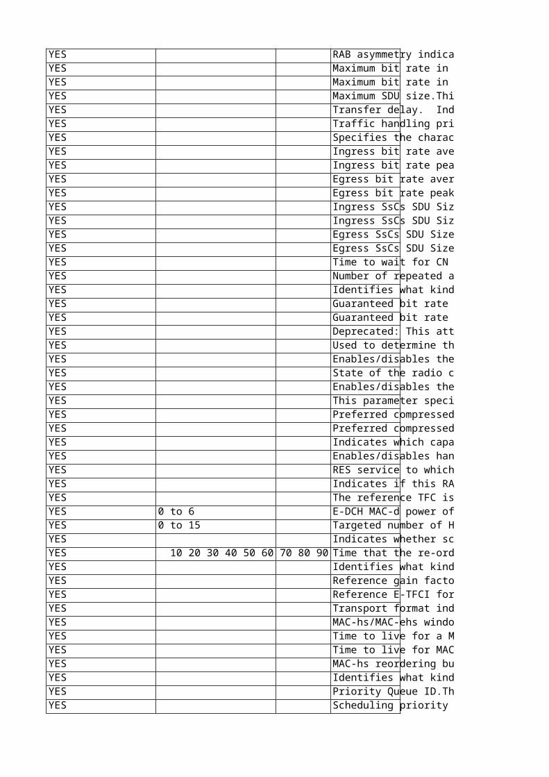
RAB asymmetry indicator.This attribute may only be changed by Ericsson personnel. Value mapping:0: Symmetric Bidirectional1: Asymmetric Unidirectional DL2: Asymmetric Unidirectional UL3: Asymmetric Bidirectional Maximum bit rate in downlink direction.Use of value is based on the RAB asymmetry indicator.This attribute may only be changed by Ericsson personnel. Unit: bps Maximum bit rate in uplink direction.Use of value is based on the RAB asymmetry indicator.This attribute may only be changed by Ericsson personnel. Unit: bps Maximum SDU size.This attribute may only be changed by Ericsson personnel. Unit: bit Transfer delay. Indicates maximum delay for 95th percentile of the distribution of delivered SDUs during the lifetime of a bearer service, where delay for an SDU is defined as the time from a request to transfer of an SDU at one SAP to its delivery to the other SAP.Used to specify the delay tolerated by the application. It allows UTRAN to set transport formats and ARQ parameters.This attribute may only be changed by Ericsson personnel. Unit: ms Traffic handling priority.This attribute may only be changed by Ericsson personnel. Specifies the characteristics of the source of submitted SDUs.This attribute may only be changed by Ericsson personnel. Value mapping:0: Speech1: Unknown Ingress bit rate average. Traffic descriptor parameter for the connection between the RNC and CN.This attribute may only be changed by Ericsson personnel. Value mapping:0: 0 bps1: 64 bps...32000: 2048000 bps (2048 kbps)Unit: 64 bps Ingress bit rate peak. Traffic descriptor parameter for the connection between the RNC and CN.This attribute may only be changed by Ericsson personnel. Value mapping:0: 0 bps1: 64 bps...32000: 2048000 bps (2048 kbps)Unit: 64 bps Egress bit rate average. Traffic descriptor parameter for the connection between the RNC and CN.This attribute may only be changed by Ericsson personnel. Value mapping:0: 0 bps1: 64 bps...32000: 2048000 bps (2048 kbps)Unit: 64 bps Egress bit rate peak. Traffic descriptor parameter for the connection between the RNC and CN.This attribute may only be changed by Ericsson personnel. Value mapping:0: 0 bps1: 64 bps...32000: 2048000 bps (2048 kbps)Unit: 64 bps Ingress SsCs SDU Size Average. Traffic Descriptor parameter for the connection between the RNC and CN.This attribute may only be changed by Ericsson personnel. Unit: octet Ingress SsCs SDU Size Peak. Traffic Descriptor parameter for the connection between the RNC and CN.This attribute may only be changed by Ericsson personnel. Unit: octet Egress SsCs SDU Size Average. Traffic Descriptor parameter for the connection between the RNC and CN.This attribute may only be changed by Ericsson personnel. Unit: octet Egress SsCs SDU Size Peak. Traffic Descriptor parameter for the connection between the RNC and CN.This attribute may only be changed by Ericsson personnel. Unit: octet Time to wait for CN response to an Iu-c initialization procedure. After this length of time, if no response has been received, RNC repeats the initialization procedure. The maximum number of repeated attempts is defined in noIucInitRep.This attribute may only be changed by Ericsson personnel. Special values:0 is used to indicate that iucInitTimer is not in use.Unit: sChange takes effect: New connections Number of repeated attempts to initialize the Iu user plane protocol, when it has failed.This attribute may only be changed by Ericsson personnel. Special values:0 is used to indicate that noIucInitRep is not in use.Change takes effect: New connections Identifies what kind of radio access bearer this MO instance represents.This attribute may only be changed by Ericsson personnel. Guaranteed bit rate in downlink direction.Use of value is based on RAB Asymmetry Indicator.Applicable for conversational and streaming (value not valid for interactive).Unit: 1 bpsThis attribute may only be changed by Ericsson personnel. Filter: TDD Guaranteed bit rate in uplink direction.Use of value is based on RAB Asymmetry Indicator.Applicable for conversational and streaming (value not valid for interactive).Unit: 1 bpsThis attribute may only be changed by Ericsson personnel. Filter: TDD Deprecated: This attribute is currently not used by the system. Changing it has no effect.Used to determine the value to which IE Activation Time (RRC) and IE CFN (RNSAP and NBAP) shall be set when starting compressed mode.This attribute may only be changed by Ericsson personnel. Value mapping:1: 752: 1203: 150Change takes effect: Next configuration of the transmission gap pattern sequence in UE, DRNC or RBS. Used to determine the value to which IE CM Configuration Change CFN (RNSAP and NBAP) and TGPS reconfiguration CFN (RRC) shall be set when stopping compressed mode.This attribute may only be changed by Ericsson personnel. Value mapping:1: 1002: 1503: 200Change takes effect: Next stop of CPM Enables/disables the possibility of HO from UMTS to GSM per RAB type.This attribute may only be changed by Ericsson personnel. Value mapping:0 : not allowed 1 : allowedChange takes effect: Ongoing connections (next change of RC state) State of the radio connection.This attribute may only be changed by Ericsson personnel. Value mapping:See UeRc class description for list of possible values and their interpretation.Dependencies: This attribute has the same value as the value part of the RDN (UeRcId). Enables/disables the possibility of IFHO per RAB state.This attribute may only be changed by Ericsson personnel. Change takes effect: Ongoing connections (next change of RC state)Filter: FDD This parameter specifies the RES service which the UeRc belongs to.This attribute may only be changed by Ericsson personnel.Filter: FDD Preferred compressed mode method for the uplink.This attribute may only be changed by Ericsson personnel. Change takes effect: Next state transitionFilter: FDD Preferred compressed mode method for the downlink.This attribute may only be changed by Ericsson personnel. Change takes effect: Next state transitionFilter: FDD Indicates which capabilities are supported by a specific UeRc. This attribute may only be changed by Ericsson personnel. Change takes effect: Next reconfiguration Filter: FDD Enables/disables handover from UMTS to GAN. Dependencies: Not used if the license ganMobility is not active. Change takes effect: Ongoing connections (next change of RC state) This attribute may only be changed by Ericsson personnel.Filter: FDD RES service to which this UeRc belongs.This attribute may only be changed by Ericsson personnel.Filter: TDD Indicates if this RAB combination is an MMTEL RAB or not.This attribute may only be changed by Ericsson personnel.Filter: FDD The reference TFC is the TFC from the TFCS of the configuration represented by the UeRc that has the most Transport Format information in the TFCS (the TFC that will result in the maximum number of TB's with largest size being applied).This attribute may only be changed by Ericsson personnel. Filter: TDD0 to 6 E-DCH MAC-d power offset used by the Outer loop power control function.This attribute may only be changed by Ericsson personnel. Unit: dB0 to 15 Targeted number of HARQ transmissions in the uplink.It is recommended that the value of this attribute should be the same for all flows under a specific UeRc instance.This attribute may only be changed by Ericsson personnel. Indicates whether scheduled or non-scheduled grant info applies for the EUL MAC-d flow.This attribute may only be changed by Ericsson personnel. 10 20 30 40 50 60 70 80 90 100 1 Time that the re-ordering entity should wait for an outstanding MAC-es PDU.It is recommended that the value of this attribute should be the same for all flows under a specific UeRc instance.This attribute may only be changed by Ericsson personnel. Unit: msChange takes effect: New connections Identifies what kind of radio bearer this MO instance represents.This attribute may only be changed by Ericsson personnel. Special values:Only the values RB_RRC, RB_PS_INTERACTIVE and RB_PS_INTERACTIVE_2 are applicable for this attribute and MO (even though the other values are allowed to be set). Reference gain factor for the UL E-DPDCH reference transport format 1.This attribute may only be changed by Ericsson personnel. Reference E-TFCI for signaled E-DPDCH gain factors.This attribute may only be changed by Ericsson personnel. Specification: 3GPP 25.321 Transport format indicator.This attribute may only be changed by Ericsson personnel. MAC-hs/MAC-ehs window size used in the RBS and the UE for MAC-hs/MAC-ehs data transfer. The parameter value setting is signaled via NBAP and RRC. If MIMO or Multi-Carrier is used for a HS-DSCH connection, the value signaled is min(32, 2 * macHsWindowSize).This attribute may only be changed by Ericsson personnel. Time to live for a MAC-hs SDU starting from the instant of its arrival into an HSDPA Priority Queue. The RBS shall use this information to discard out-of-data MAC-hs SDUs from the HSDPA Priority Queues. The parameter value setting is signaled via NBAP.This attribute may only be changed by Ericsson personnel.Unit: ms Time to live for MAC-hs SDU. The Re-ordering release timer T1 controls the stall avoidance in the UE reordering buffer. The parameter value setting is signaled via NBAP and RRC.This attribute may only be changed by Ericsson personnel.Unit: ms MAC-hs reordering buffer size.This attribute may only be changed by Ericsson personnel. Unit: kB (1000 bytes) Identifies what kind of radio bearer this MO instance represents. Special values:Only the values RB_RRC, RB_PS_INTERACTIVE_HS, RB_PS_INTERACTIVE_HS_2, RB_PS_INTERACTIVE_HS_3, and RB_PS_STREAMING_HS are applicable for this attribute and MO (even though the other values are allowed to be set).This attribute may only be changed by Ericsson personnel. Filter: FDD Priority Queue ID.This attribute may only be changed by Ericsson personnel. Filter: TDD Scheduling priority of a priority queue.0 - Lowest Priority?5 - Highest PriorityThis attribute may only be changed by Ericsson personnel. Filter: TDD
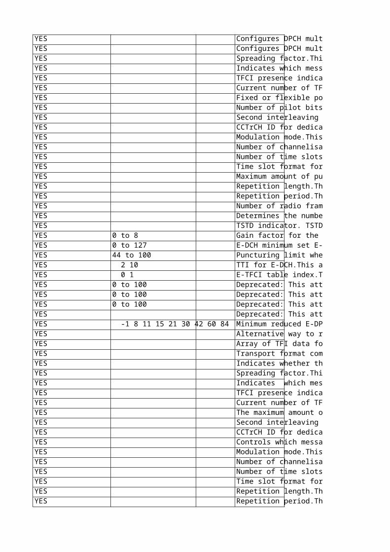
Configures DPCH multiplexing in the downlink for two HSDPA users. This attribute may only be changed by Ericsson personnel.Filter: TDD Configures DPCH multiplexing in the downlink for four HSDPA users. This attribute may only be changed by Ericsson personnel.Filter: TDD Spreading factor.This attribute may only be changed by Ericsson personnel. $FDD{"Value mapping:0: SF 41: SF 82: SF 163: SF 324: SF 645: SF 1286: SF 2567: SF 512"}$TDD{"Value mapping:0: SF 11: SF 16"} Indicates which message part format the DPCH shall use.This attribute may only be changed by Ericsson personnel. TFCI presence indicator. This has the same meaning as the RRC parameter "TFCI existence".DPCH info.This attribute may only be changed by Ericsson personnel. Value mapping:0: No = TFCI not present; same as "TFCI existence" = FALSE1: Yes = TFCI present; same as "TFCI existence" = TRUE Current number of TFCs.This attribute may only be changed by Ericsson personnel. Fixed or flexible position for TrCH on DPCH.This attribute may only be changed by Ericsson personnel. Value mapping:0: FIXED1: FLEXIBLEFilter: FDD Number of pilot bits for DPCH.The number of pilot bits needs to be signaled to the UE in case the downlink physical connection uses spreading factor 128 or 256. In all other cases the UE calculates the number of pilot bits based on slot format information. The number of pilot bits is not signaled towards the RBS. For downlink physical connections using other spreading factors, the configured value will not be used by the RNC, but has to be set anyway since the parameter is defined as mandatory in the MOM. Any of the defined values will work.This attribute may only be changed by Ericsson personnel. Filter: FDD Second interleaving mode.This attribute may only be changed by Ericsson personnel.Value mapping:0: Frame interleaving1: Time Slot interleaving Filter: TDD CCTrCH ID for dedicated and shared channels. Identifies unambiguously a downlink CCTrCH within a radio link.This attribute may only be changed by Ericsson personnel.Filter: TDDReplaces: tdCcTrChId Modulation mode.This attribute may only be changed by Ericsson personnel.Value mapping:0: QPSK1: 8PSKFilter: TDDReplaces: tdModulation Number of channelisation codes per time slot. This attribute may only be changed by Ericsson personnel. Filter: TDDReplaces: tdNoChCodesPerTimeSlot Number of time slots. This attribute may only be changed by Ericsson personnel. Filter: TDDReplaces: tdNoTimeSlots Time slot format for all physical channels except the first (meaning the physical channel with the least number of time slots and least number of channels). This attribute may only be changed by Ericsson personnel. Filter: TDDReplaces: tdOtherTimeSlotFormat Maximum amount of puncturing used for DCH in downlink rate matching.This attribute may only be changed by Ericsson personnel.Value mapping:0: 40%1: 44%2: 48%...15: 100% Filter: TDDReplaces: tdPunctureLimit Repetition length.This attribute may only be changed by Ericsson personnel.Specification: Chapter 8.6.6.16 in TS 25.331 V4.17.0Filter: TDDReplaces: tdRepetitionLength Repetition period.This attribute may only be changed by Ericsson personnel.Value mapping:0: RepetitionPeriod_v11: RepetitionPeriod_v22: RepetitionPeriod_v43: RepetitionPeriod_v84: RepetitionPeriod_v165: RepetitionPeriod_v326: RepetitionPeriod_v64Specification: Chapter 8.6.6.16 in TS 25.331 V4.17.0 Filter: TDDReplaces: tdRepetitionPeriod Number of radio frames to be used as the offset for the DPCH. Used for determining the frame offset from the SFN timing in a cell.This attribute may only be changed by Ericsson personnel.Disturbances:Changing this attribute will affect ongoing traffic.Filter: TDDReplaces: tdTddDpchOffsetValue Determines the number of bits for the TFCI bits code word.Value mapping:0: v41: v82: v163: v32In case of 8 PSK in 1.28Mcps:v4 corresponds to 6 TFCI code word bits.v8 corresponds to 12 TFCI code word bits.v16 corresponds to 24 TFCI code word bits.v32 corresponds to 48 TFCI code word bits.This attribute may only be changed by Ericsson personnel.Filter: TDDReplaces: tdTfciCoding TSTD indicator. TSTD can be used to overcome the time varying characteristics of the communication channel, Similar to the IE "Tx diversity indicator" for FDD, "TSTD indicator" can be defined and used to inform the application of TSTD to DPCH.This attribute may only be changed by Ericsson personnel.Value mapping:0: active1: inactive Filter: TDDReplaces: tdTstdIndicator0 to 8 Gain factor for the UL E-DPCCH.This attribute may only be changed by Ericsson personnel. 0 to 127 E-DCH minimum set E-TFCI.This attribute may only be changed by Ericsson personnel. Specification: 3GPP 25.32144 to 100 Puncturing limit when increasing the number of used channelization codes. Only applies when the number of code channels is less than the maximum allowed by the UE capability and restrictions imposed by UTRAN.This attribute may only be changed by Ericsson personnel. Resolution: 4 2 10 TTI for E-DCH.This attribute may only be changed by Ericsson personnel. Unit: ms 0 1 E-TFCI table index.This attribute may only be changed by Ericsson personnel. Specification: 3GPP 25.3210 to 100 Deprecated: This attribute is currently not used by the system. Changing it has no effect.TTI budget for an SRB mapped on E-DCH.This attribute may only be changed by Ericsson personnel. Unit: %0 to 100 Deprecated: This attribute is currently not used by the system. Changing it has no effect.TTI budget for a SIP RAB mapped on non-scheduled E-DCH.This attribute may only be changed by Ericsson personnel. Unit: %0 to 100 Deprecated: This attribute is currently not used by the system. Changing it has no effect.TTI budget for scheduled flows on E-DCH.This attribute may only be changed by Ericsson personnel. Unit: % Deprecated: This attribute is currently not used by the system. Changing it has no effect.Defines the E-DCH multiplexing option for this E-DCH radio configuration.Value mapping:0: No multiplexing except among scheduled flows.1: Multiplexing among non-scheduled flows allowed except between SRB and a non-scheduled SIP (if exists), among scheduled flows allowed, but not between scheduled and non-scheduled flows.2: All multiplexing allowed except between SRB and scheduled flows or non-scheduled SIP (if exists).3: All multiplexing allowed except between SRB and a non-scheduled SIP (if exists). This attribute may only be changed by Ericsson personnel. -1 8 11 15 21 30 42 60 84 Minimum reduced E-DPDCH gain factor. When E-DCH is configured, if the total UE transmit power (after applying DPCCH power adjustments and gain factors) would exceed the available maximum power, the UE shall firstly reduce the E-DPDCH power with the E-DPDCH gain factor so that the total transmit power would be equal to the available maximum power. If the total transmit power is still higher than the available maximum power after applying the gain factor the E-DPDCH and the DPCCH are equally scaled to meet the available maximum power. This parameter configures the minimum factor to be used by Rel-8 UEs for reduction of the E-DPDCH gain factor. The configured value is divided by 15 to obtain the scaling factor used by the UE. -1 means that this attribute is not applicable for this instance.This attribute may only be changed by Ericsson personnel.Unit: 1 / 15 Change takes effect: Immediately Alternative way to represent TFCThis attribute may only be changed by Ericsson personnel. Filter: TDD Array of TFI data for this UeRcPhyChTfc for all used TrChs of this Radio Connection.This attribute may only be changed by Ericsson personnel. Filter: TDD Transport format combination id.This attribute may only be changed by Ericsson personnel. Filter: TDD Indicates whether this instance is used for uplink or downlink.0: UL1: DLThis attribute may only be changed by Ericsson personnel. Filter: TDD Spreading factor.This attribute may only be changed by Ericsson personnel. $FDD{"Value mapping:0: SF 41: SF 82: SF 163: SF 324: SF 645: SF 1286: SF 2567: SF 512"}$TDD{"Value mapping:0: SF 11: SF 22: SF 43: SF 84: SF 16 "} Indicates which message part format the DPCH shall use for DPCCH.This attribute may only be changed by Ericsson personnel. Filter: FDD TFCI presence indicator.DPCH info.This attribute may only be changed by Ericsson personnel. Value mapping:0: No = TFCI not present1: Yes = TFCI present Current number of TFCs.This attribute may only be changed by Ericsson personnel. The maximum amount of puncturing for DCH in uplink rate matching.This attribute may only be changed by Ericsson personnel. Value mapping:0: 40 %1: 44 %2: 48 %...15: 100 %Unit: % Second interleaving mode.This attribute may only be changed by Ericsson personnel.Value mapping: 0: Frame interleaving1: Time Slot interleaving Filter: TDDReplaces: td2ndInterleavingMode CCTrCH ID for dedicated and shared channels. Identifies unambiguously an uplink CCTrCH within a radio link.This attribute may only be changed by Ericsson personnel. Filter: TDDReplaces: tdCcTrChId Controls which message part format the DPCH shall use as the time slot format for the first physical channel (meaning the physical channel with the least number of time slots and least number of channels). This attribute may only be changed by Ericsson personnel. Filter: TDDReplaces: tdDpchSlotFormat Modulation mode.This attribute may only be changed by Ericsson personnel.Value mapping:0: QPSK1: 8PSK Filter: TDDReplaces: tdModulation Number of channelisation codes per time slot. This attribute may only be changed by Ericsson personnel.Filter: TDDReplaces: tdNoChCodesPerTimeSlot Number of time slots. This attribute may only be changed by Ericsson personnel.Filter: TDDReplaces: tdNoTimeSlots Time slot format for all physical channels except the first (meaning the physical channel with the least number of time slots and least number of channels). This attribute may only be changed by Ericsson personnel.Filter: TDDReplaces: tdOtherTimeSlotFormat Repetition length.This attribute may only be changed by Ericsson personnel.Specification: Chapter 8.6.6.16 in TS 25.331 V4.17.0Filter: TDDReplaces: tdRepetitionLength Repetition period.This attribute may only be changed by Ericsson personnel.Value mapping: 0: RepetitionPeriod_v11: RepetitionPeriod_v22: RepetitionPeriod_v43: RepetitionPeriod_v84: RepetitionPeriod_v165: RepetitionPeriod_v326: RepetitionPeriod_v64Specification: Chapter 8.6.6.16 in TS 25.331 V4.17.0 Filter: TDDReplaces: tdRepetitionPeriod
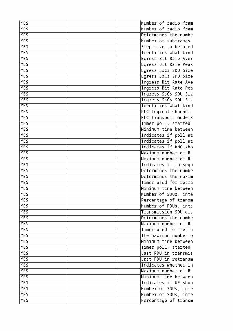
Number of radio frames between special burst transmissions during DTX.This attribute may only be changed by Ericsson personnel. Filter: TDDReplaces: tdSpecialBurstScheduling Number of radio frames to be used as the offset for the DPCH. Used for determining the frame offset from the SFN timing in a cell.This attribute may only be changed by Ericsson personnel.Disturbances:Changing this attribute will affect ongoing traffic.Filter: TDDReplaces: tdTddDpchOffsetValue Determines the number of bits for the TFCI bits code word.Value mapping: 0: v41: v82: v163: v32In case of 8 PSK in 1.28Mcps:v4 corresponds to 6 TFCI code word bits.v8 corresponds to 12 TFCI code word bits.v16 corresponds to 24 TFCI code word bits.v32 corresponds to 48 TFCI code word bits.This attribute may only be changed by Ericsson personnel.Filter: TDDReplaces: tdTfciCoding Number of subframes between two adjustments of the uplink transmission timing.This attribute may only be changed by Ericsson personnel.Filter: TDDReplaces: tdUlSynchronizationStepFrequency Step size to be used for adjustment of the uplink transmission timing.This attribute may only be changed by Ericsson personnel.Unit: 1/8 chipFilter: TDDReplaces: tdUlSynchronizationStepSize Identifies what kind of radio bearer this MO instance represents.Value RB_RRC is not applicable for this attribute and MO (but is nonetheless allowed to be set).This attribute may only be changed by Ericsson personnel. Egress Bit Rate Average Traffic Descriptor parameter for the AAL2 connection between the RNC and RBS for the RAB leg.0: 0 bit/s1: 64 bit/s..32000: 2048000 bit/s (2048 kbit/s)This attribute may only be changed by Ericsson personnel. Filter: TDD Egress Bit Rate PeakTraffic Descriptor parameter for the AAL2 connection between the RNC and RBS for the RAB leg.0: 0 bit/s1: 64 bit/s..32000: 2048000 bit/s (2048 kbit/s)This attribute may only be changed by Ericsson personnel. Filter: TDD Egress SsCs SDU Size Average. Traffic Descriptor parameter for the AAL2 connection between the RNC and RBS for the RAB leg.Unit: 1 octetThis attribute may only be changed by Ericsson personnel. Filter: TDD Egress SsCs SDU Size Peak. Traffic Descriptor parameter for the AAL2 connection between the RNC and RBS for the RAB leg.Unit: 1 octetThis attribute may only be changed by Ericsson personnel. Filter: TDD Ingress Bit Rate AverageTraffic Descriptor parameter for the AAL2 connection between the RNC and RBS for the RAB leg.0: 0 bit/s1: 64 bit/s..32000: 2048000 bit/s (2048 kbit/s)This attribute may only be changed by Ericsson personnel. Filter: TDD Ingress Bit Rate PeakTraffic Descriptor parameter for the AAL2 connection between the RNC and RBS for the RAB leg.0: 0 bit/s1: 64 bit/s..32000: 2048000 bit/s (2048 kbit/s)This attribute may only be changed by Ericsson personnel. Filter: TDD Ingress SsCs SDU Size Average. Traffic Descriptor parameter for the AAL2 connection between the RNC and RBS for the RAB leg.Unit: 1 octetThis attribute may only be changed by Ericsson personnel. Filter: TDD Ingress SsCs SDU Size Peak. Traffic Descriptor parameter for the AAL2 connection between the RNC and RBS for the RAB leg.Unit: 1 octetThis attribute may only be changed by Ericsson personnel. Filter: TDD Identifies what kind of radio bearer this MO instance represents.This attribute may only be changed by Ericsson personnel. Special values:Value RB_PACKET_ADCH, RB_PACKET_ADCH_2, RB_PACKET_ADCH_3 and RB_STREAMING_ADCH are not applicable for this attribute and MO (but are nonetheless allowed to be set). RLC Logical Channel Type.RLC info common to RNC side and UE sideThis attribute may only be changed by Ericsson personnel. Value mapping:0: DCCH Dedicated Control Ch. Valid only on DCS side1: DTCH Dedicated Traffic Ch. Valid only on DCS side2: BCCH Broadcast Control Channel. Valid only on CCS side.3: CCCH Common Control Channel. Valid only on CCS side.4: PCCH Paging Control Channel. Valid only on CCS side. RLC transport mode.RLC info common to RNC side and UE side.It is assumed that the same value is used for both DL and UL.0: Acknowledged (AM)1: Transparent (TM)2: Unacknowledged (UM)This attribute may only be changed by Ericsson personnel. Timer poll, started when poll is transmitted. New poll is sent when timer expires and no STATUS is received.RLC info on RNC side. Valid only for RLC mode = AM.This attribute may only be changed by Ericsson personnel. Special values:0: not used Unit: ms Minimum time between STATUS reports.RLC info on RNC side. Valid only for RLC mode = AM.This attribute may only be changed by Ericsson personnel. Special values:0: not used Unit: ms Indicates if poll at last PDU in transmission buffer is used or not.RLC info on RNC side. Valid only for RLC mode = AM.This attribute may only be changed by Ericsson personnel. Value mapping:0: poll not used1: poll used Indicates if poll at last PDU in retransmission buffer is used or not.RLC info on RNC side. Valid only for RLC mode = AM.This attribute may only be changed by Ericsson personnel. Value mapping:0: poll not used1: poll used Indicates if RNC should send a STATUS report for each detected PDU missing.RLC info on RNC side. Valid only for RLC mode = AM.This attribute may only be changed by Ericsson personnel. Value mapping:0: RNC shall not send STATUS reports1: RNC shall send STATUS reports Maximum number of RLC PDUs sent without getting them acknowledged. RLC info on RNC side. Valid only for SRB with RLC mode = AM.This attribute may only be changed by Ericsson personnel. Maximum number of RLC PDUs in the receiving buffer. RLC info on RNC side. Valid only for SRB with RLC mode = AM.This attribute may only be changed by Ericsson personnel. Indicates if in-sequence delivery shall be used or not.RLC info on RNC side. Valid only for RLC mode = UM and AM.This attribute may only be changed by Ericsson personnel. Value mapping:0: the value can be configured but in-sequence delivery will still be used, that is, in-sequence delivery is predefined.1: in-sequence delivery shall be used Determines the number of transmissions of a PDU before a SDU is discarded or reset procedure is initiated.The maximum number of transmissions of a PDU equals MaxDat-1.RLC info on RNC side. Valid only for RLC mode = AM.This attribute may only be changed by Ericsson personnel. Determines the maximum number of transmissions of a reset PDU.The maximum number of transmissions of a reset PDU equals MaxRst-1.RLC info on RNC side. Valid only for RLC mode = AM.This attribute may only be changed by Ericsson personnel. Timer used for retransmission of reset PDU. This attribute may only be changed by Ericsson personnel. Special values:0: not used Unit: ms Minimum time between polls. Used in RNC. This attribute may only be changed by Ericsson personnel. Special values:0: not used Unit: ms Number of SDUs, interval between polling.This attribute may only be changed by Ericsson personnel. Special values:0: attribute not used Percentage of transmission windows, threshold for polling.This attribute may only be changed by Ericsson personnel. Special values:0: not usedUnit: % Number of PDUs, interval between pollings.This attribute may only be changed by Ericsson personnel. Special values:0: not used Transmission SDU discard mode.RLC info on UE side UL. This attribute may only be changed by Ericsson personnel. Value mapping:0: Timer Based Explicit (can be configured but is not used)1: Timer Based No Explicit (can be configured but is not used)2: Max Dat (can be configured but is not used)3: No Discard (AM), SDU Discard not configured (TM and UM) Determines the number of transmissions of a PDU before a SDU is discarded or reset procedure is initiated.The number of transmissions is equal to MaxDat - 1.RLC info on UE side UL. Valid only for RLC mode = AM.This attribute may only be changed by Ericsson personnel. Value mapping: 2: MaxDat = 3 3: 4 4: 5 5: 6 6: 7 7: 8 8: 9 9: 1010: 1511: 2012: 2513: 3014: 3515: MaxDat = 40 Maximum number of RLC PDUs sent without getting them acknowledged. RLC info on UE side UL. Valid only for SRB with RLC mode = AM. This attribute may only be changed by Ericsson personnel. Value mapping: 0:1 Max PDU sent 1:8 2:16 3:32 4:64 5:128 6:256 7:512 8:768 9:1024 10:1536 11:2047 12:2560 13:3072 14:3584 Timer used for retransmission of reset PDU.RLC info on UE side UL. This attribute may only be changed by Ericsson personnel. Value mapping: 0: 50 ms 1: 100 ms 2: 150 ms ..11: 600 ms12: 700 ms..15: 1000 msUnit: ms The maximum number of transmissions of reset PDU equals MaxRst-1.RLC info on UE side UL. This attribute may only be changed by Ericsson personnel. Value mapping:0: MaxRst = 11: 42: 63: 84: 125: 166: 247: MaxRst =32 Minimum time between polls.RLC polling info on UE side UL. Valid only for RLC mode = AM.This attribute may only be changed by Ericsson personnel. Special values: -1: not used 10..550 ms with resolution 10600..1000ms with resolution 50Unit: ms Timer poll, started when poll is transmitted. New poll is sent when timer expires and no STATUS is received.RLC polling info on UE side UL. Valid only for RLC mode = AM.This attribute may only be changed by Ericsson personnel. Special values:-1: not used 10 .. 550 ms with resolution 10600 ..1000ms with resolution 50Unit: ms Last PDU in transmission poll.RLC polling info on UE side UL. This attribute may only be changed by Ericsson personnel. Value mapping:0: not last PDU in Transmission Poll1: last PDU in Transmission Poll Last PDU in retransmission poll.RLC polling info on UE side UL. This attribute may only be changed by Ericsson personnel. Value mapping:0: not last PDU in Retransmission Poll1: last PDU in Retransmission Poll Indicates whether in-sequence delivery shall be used.It is assumed that the same value is used for both DL and UL.RLC info on UE side DL. Valid for RLC mode = AM and UM.This attribute may only be changed by Ericsson personnel. Value mapping:0: in-sequence delivery shall not be used1: in-sequence delivery shall be used Maximum number of RLC PDUs in the receiving buffer. RLC info on UE side DL. Valid only for SRB with RLC mode = AM. This attribute may only be changed by Ericsson personnel. Value mapping: 0:1 PDU in buffer 1:8 2:16 3:32 4:64 5:128 6:256 7:512 8:768 9:1024 10:1536 11:2047 12:2560 13:3072 14:3584 15:4095 Minimum time between STATUS reports.RLC info on UE side DL. Valid only for RLC mode = AM.This attribute may only be changed by Ericsson personnel. Special values: -1: not used 10..550 ms with resolution 10600..1000ms with resolution 50Unit: ms Indicates if UE should send a STATUS report for each detected PDU missing. This value is also used in DL RLC Status Info sent on RRC.RLC info on UE side DL. Valid only for RLC mode = AM.This attribute may only be changed by Ericsson personnel. Value mapping:0: UE shall not send STATUS reports1: UE shall send STATUS reports Number of SDUs, interval between pollings.This attribute may only be changed by Ericsson personnel. Value mapping:-1 Attribute not used.0 1 SDU interval 1 4 SDU intervals 2 16 SDU intervals 3 64 SDU intervals Number of SDUs, interval between polling.This attribute may only be changed by Ericsson personnel. Value mapping:-1 Attribute not used.0 1 PDU interval 1 2 PDU interval 2 4 PDU interval 3 8 PDU interval 4 16 PDU interval 5 32 PDU interval 6 64 PDU interval 7 128 PDU interval Percentage of transmission windows, threshold for polling.This attribute may only be changed by Ericsson personnel. Special values:0: not usedUnit: %
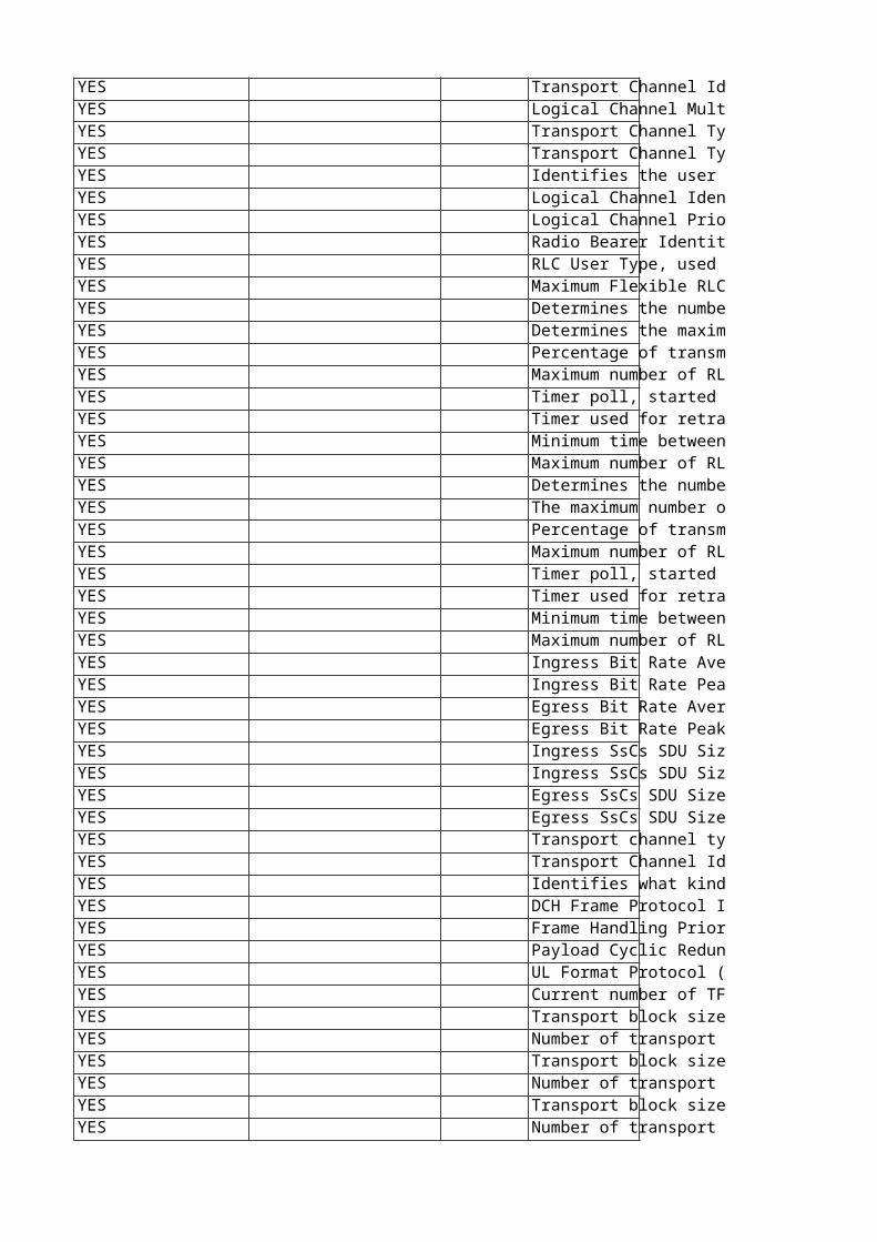
Transport Channel Identity (DCH Id) which gives the association between RB and Transport Channel.RB Mapping Info. This attribute may only be changed by Ericsson personnel. Logical Channel Multiplexing indicator in MacD.RB Mapping Info. This attribute may only be changed by Ericsson personnel. Value mapping:0: multiplexing is not performed1: multiplexing is performed Transport Channel Type DL.RB Mapping Info.This attribute may only be changed by Ericsson personnel. Value mapping:0: DCH1: FACH2: DSCH3: HS-DSCH Transport Channel Type UL.RB Mapping Info. Valid for RLC mode = UM, AM and TM.This attribute may only be changed by Ericsson personnel. Value mapping:-1: Not Applicable0: DCH1: RACH2: CPCH3: E-DCH Identifies the user of this radio bearer.This attribute may only be changed by Ericsson personnel. Filter: FDD Logical Channel Identity.Used when several RBs are muxed to single DCH (1 is used for first RB of RRC).RB Mapping Info.This attribute may only be changed by Ericsson personnel. Filter: TDD Logical Channel PriorityUsed when several RBs are muxed to single DCH (1 is used for highest priority i.e. for the first RB of RRC).RB Mapping Info.This attribute may only be changed by Ericsson personnel. Filter: TDD Radio Bearer Identity.1: SRB12: SRB23: SRB34: SRB45-32:used by other types of radio bearersThis attribute may only be changed by Ericsson personnel. Filter: TDD RLC User Type, used to inform the RLC about which interface to use.RLC info is common to both the RNC side and the UE side.0=Rrc1=Speech2=Udi3=PsInteractive4=CsStreaming5=PsStreamingThis attribute may only be changed by Ericsson personnel. Filter: TDD Maximum Flexible RLC PDU size.This attribute may only be changed by Ericsson personnel.Dependencies: The value used for this RAB is the minimum of maxMacdPduSizeExtended and IurLink::maxMacdPduSizeExtendedUnit: bytesChange takes effect: New connections Determines the number of transmissions of a PDU before a SDU is discarded or reset procedure is initiated.The maximum number of transmissions of a PDU equals MaxDat-1.This attribute may only be changed by Ericsson personnel. Determines the maximum number of transmissions of a reset PDU.The maximum number of transmissions of a reset PDU equals MaxRst-1.This attribute may only be changed by Ericsson personnel. Percentage of transmission windows, threshold for polling.This attribute may only be changed by Ericsson personnel. Unit: % Maximum number of RLC PDUs in the receiving buffer. RLC info on RNC side. Valid only for RLC mode = AM.This attribute may only be changed by Ericsson personnel. Timer poll, started when poll is transmitted. New poll is sent when timer expires and no STATUS is received.RLC info on RNC side. Valid only for RLC mode = AM.This attribute may only be changed by Ericsson personnel. Unit: ms Timer used for retransmission of reset PDU. This attribute may only be changed by Ericsson personnel. Unit: ms Minimum time between STATUS reports.RLC info on RNC side. Valid only for RLC mode = AM.This attribute may only be changed by Ericsson personnel. Unit: ms Maximum number of RLC PDUs sent without getting them acknowledged. RLC info on RNC side. Valid only for RLC mode = AM. This attribute may only be changed by Ericsson personnel. Determines the number of transmissions of a PDU before a SDU is discarded or reset procedure is initiated.The number of transmissions is equal to MaxDat - 1.This attribute may only be changed by Ericsson personnel. Value mapping: 2: MaxDat = 3 3: 4 4: 5 5: 6 6: 7 7: 8 8: 9 9: 1010: 1511: 2012: 2513: 3014: 3515: MaxDat = 40 The maximum number of transmissions of reset PDU equals MaxRst-1.This attribute may only be changed by Ericsson personnel. Value mapping:0: MaxRst = 11: 42: 63: 84: 125: 166: 247: MaxRst =32 Percentage of transmission windows, threshold for polling.This attribute may only be changed by Ericsson personnel. Unit: % Maximum number of RLC PDUs in the receiving buffer. RLC info on UE side DL. Valid only for SRB with RLC mode = AM. This attribute may only be changed by Ericsson personnel. Value mapping: 0:1 PDU in buffer 1:8 2:16 3:32 4:64 5:128 6:256 7:512 8:768 9:1024 10:1536 11:2047 12:2560 13:3072 14:3584 15:4095 Timer poll, started when poll is transmitted. New poll is sent when timer expires and no STATUS is received.RLC polling info on UE side UL. Valid only for RLC mode = AM.This attribute may only be changed by Ericsson personnel. Value mapping:10 .. 550 ms with resolution 10600 ..1000ms with resolution 50Unit: ms Timer used for retransmission of reset PDU.RLC info on UE side UL. This attribute may only be changed by Ericsson personnel. Value mapping: 0: 50 ms 1: 100 ms 2: 150 ms ..11: 600 ms12: 700 ms..15: 1000 msUnit: ms Minimum time between STATUS reports.RLC info on UE side DL. Valid only for RLC mode = AM.This attribute may only be changed by Ericsson personnel. Value mapping:10..550 ms with resolution 10600..1000ms with resolution 50Unit: ms Maximum number of RLC PDUs sent without getting them acknowledged. RLC info on UE side UL. Valid only for RLC mode = AM.This attribute may only be changed by Ericsson personnel. Value mapping: 0:1 Max PDU sent 1:8 2:16 3:32 4:64 5:128 6:256 7:512 8:768 9:1024 10:1536 11:2047 12:2560 13:3072 14:3584 Ingress Bit Rate Average Traffic Descriptor parameter for the AAL2 connection between the RNC and RBS for the RRC leg.0: 0 bit/s1: 64 bit/s..32000: 2048000 bit/s (2048 kbit/s)This attribute may only be changed by Ericsson personnel. Filter: TDD Ingress Bit Rate PeakTraffic Descriptor parameter for the AAL2 connection between the RNC and RBS for the RRC leg.0: 0 bit/s1: 64 bit/s..32000: 2048000 bit/s (2048 kbit/s)This attribute may only be changed by Ericsson personnel. Filter: TDD Egress Bit Rate AverageTraffic Descriptor parameter for the AAL2 connection between the RNC and RBS for the RRC leg.0: 0 bit/s1: 64 bit/s..32000: 2048000 bit/s (2048 kbit/s)This attribute may only be changed by Ericsson personnel. Filter: TDD Egress Bit Rate PeakTraffic Descriptor parameter for the AAL2 connection between the RNC and RBS for the RRC leg.0: 0 bit/s1: 64 bit/s..32000: 2048000 bit/s (2048 kbit/s)This attribute may only be changed by Ericsson personnel. Filter: TDD Ingress SsCs SDU Size Average in octets.Traffic Descriptor parameter for the AAL2 connection between the RNC and RBS for the RRC leg.This attribute may only be changed by Ericsson personnel. Filter: TDD Ingress SsCs SDU Size Peak in octets.Traffic Descriptor parameter for the AAL2 connection between the RNC and RBS for the RRC leg.This attribute may only be changed by Ericsson personnel. Filter: TDD Egress SsCs SDU Size Average in octets.Traffic Descriptor parameter for the AAL2 connection between the RNC and RBS for the RRC leg.This attribute may only be changed by Ericsson personnel. Filter: TDD Egress SsCs SDU Size Peak in octets.Traffic Descriptor parameter for the AAL2 connection between the RNC and RBS for the RRC leg.This attribute may only be changed by Ericsson personnel. Filter: TDD Transport channel type.This attribute may only be changed by Ericsson personnel. Filter: TDD Transport Channel Identity.This attribute may only be changed by Ericsson personnel. Identifies what kind of radio bearer this MO instance represents.This attribute may only be changed by Ericsson personnel. Special values:Values RB_PS_INTERACTIVE_HS, RB_PS_INTERACTIVE_2, RB_PS_INTERACTIVE_3, RB_PS_INTERACTIVE_HS_2, RB_PS_INTERACTIVE_HS_3, RB_PACKET_ADCH_2 and RB_PACKET_ADCH_3, RB_PS_STREAMING_HS are not applicable for this attribute and MO (but are nonetheless allowed to be set). DCH Frame Protocol Identity. This is the group that a DCH belongs to. In case of coordinated DCHs, all of them shall have the same attribute value.Frame Handling parameter.This attribute may only be changed by Ericsson personnel. Frame Handling Priority.Frame Handling parameter.This attribute may only be changed by Ericsson personnel. Value mapping: 0: Lowest priority...15: Highest priority Payload Cyclic Redundancy Check (CRC) usage indicator (to SP and NBAP/RRC).Frame Handling parameter.Note: NBAP/RRC messages use the opposite enumeration as shown below.This attribute may only be changed by Ericsson personnel. Value mapping:0: False1: True UL Format Protocol (NBAP).Frame Handling parameter.This attribute may only be changed by Ericsson personnel. Value mapping:-1: Not Applicable0: Normal1: Silent Current number of TFs defined in downlink.This attribute may only be changed by Ericsson personnel. Transport block size for this TF in downlink.This attribute may only be changed by Ericsson personnel. Unit: bits Number of transport blocks for this TF in downlink.This attribute may only be changed by Ericsson personnel. Transport block size for this TF in downlink.This attribute may only be changed by Ericsson personnel. Unit: bits Number of transport blocks for this TF in downlink.This attribute may only be changed by Ericsson personnel. Transport block size for this TF in downlink.This attribute may only be changed by Ericsson personnel. Unit: bits Number of transport blocks for this TF in downlink.This attribute may only be changed by Ericsson personnel.
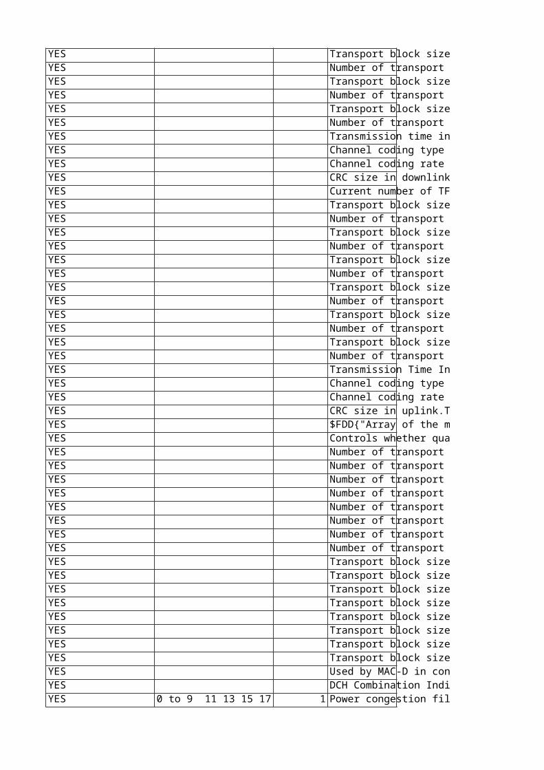
Transport block size for this TF in downlink.This attribute may only be changed by Ericsson personnel. Unit: bits Number of transport blocks for this TF in downlink.This attribute may only be changed by Ericsson personnel. Transport block size for this TF in downlink.This attribute may only be changed by Ericsson personnel. Unit: bits Number of transport blocks for this TF in downlink.This attribute may only be changed by Ericsson personnel. Transport block size for this TF in downlink.This attribute may only be changed by Ericsson personnel. Unit: bits Number of transport blocks for this TF in downlink.This attribute may only be changed by Ericsson personnel. Transmission time interval in downlink.This attribute may only be changed by Ericsson personnel. Value mapping:0: 10 ms1: 20 ms2: 40 ms3: 80 ms Unit: ms Channel coding type in downlink.This attribute may only be changed by Ericsson personnel. Value mapping:0: No Coding1: Convolutional2: Turbo Channel coding rate in downlink.This attribute may only be changed by Ericsson personnel. Value mapping:0: Coding rate = 1/21: Coding rate = 1/3 CRC size in downlink.This attribute may only be changed by Ericsson personnel. Value mapping:0: 0 bits1: 82: 123: 164: 24 bitsUnit: bits Current number of TFs defined in uplink.This attribute may only be changed by Ericsson personnel. Special values:-1: Not Applicable Transport block size for this TF in uplink.This attribute may only be changed by Ericsson personnel. Unit: bits Number of transport blocks for this TF in uplink.This attribute may only be changed by Ericsson personnel. Transport block size for this TF in uplink.This attribute may only be changed by Ericsson personnel. Unit: bits Number of transport blocks for this TF in uplink.This attribute may only be changed by Ericsson personnel. Transport block size for this TF in uplink.This attribute may only be changed by Ericsson personnel. Unit: bits Number of transport blocks for this TF in uplink.This attribute may only be changed by Ericsson personnel. Transport block size for this TF in uplink.This attribute may only be changed by Ericsson personnel. Unit: bits Number of transport blocks for this TF in uplink.This attribute may only be changed by Ericsson personnel. Transport block size for this TF in uplink.This attribute may only be changed by Ericsson personnel. Unit: bits Number of transport blocks for this TF in uplink.This attribute may only be changed by Ericsson personnel. Transport block size for this TF in uplink.This attribute may only be changed by Ericsson personnel. Unit: bits Number of transport blocks for this TF in uplink.This attribute may only be changed by Ericsson personnel. Transmission Time Interval in uplink.This attribute may only be changed by Ericsson personnel. Value mapping:-1: Not Applicable0: 10 ms1: 20 ms2: 40 ms3: 80 ms Unit: ms Channel coding type in uplink.This attribute may only be changed by Ericsson personnel. Value mapping:0: No Coding1: Convolutional2: Turbo Channel coding rate in uplink.This attribute may only be changed by Ericsson personnel. Value mapping:-1: Not Applicable0: Coding rate = 1/21: Coding rate = 1/3 CRC size in uplink.This attribute may only be changed by Ericsson personnel. Value mapping:-1: Not Applicable0: 0 bits1: 82: 123: 164: 24 bitsUnit: bits $FDD{"Array of the maximum Transport Formats (TFIs) allowed for this TrCH.The first element in the array specifies the maximum TFI for TFC Subset 0, the second element specifies the maximum TFI for TFC Subset 1, and so forth."}$TDD{"Element [0] is used as the equivalent of rateMatchingAttrDlTdd: Rate matching attribute in downlink.Element [1] is used as the equivalent of rateMatchingAttrUlTdd: Rate matching attribute in uplink.The remaining elements are not used."}The attribute must have all elements set.This attribute may only be changed by Ericsson personnel. Special values:-1: not applicable Controls whether quality evaluation is used for the downlink transport channel.Value mapping: 0: Quality evaluation not used1: Quality evaluation used2: Quality evaluation IE will not be sent in the NBAP message.This attribute may only be changed by Ericsson personnel. Filter: TDDReplaces: tdDlQeSelector Number of transport blocks for this TF in downlink.This attribute may only be changed by Ericsson personnel. Filter: TDDReplaces: tdNoOfTbTf6Dl Number of transport blocks for this TF in uplink.This attribute may only be changed by Ericsson personnel. Filter: TDDReplaces: tdNoOfTbTf6Ul Number of transport blocks for this TF in downlink.This attribute may only be changed by Ericsson personnel. Filter: TDDReplaces: tdNoOfTbTf7Dl Number of transport blocks for this TF in uplink.This attribute may only be changed by Ericsson personnel. Filter: TDDReplaces: tdNoOfTbTf7Ul Number of transport blocks for this TF in downlink.This attribute may only be changed by Ericsson personnel. Filter: TDDReplaces: tdNoOfTbTf8Dl Number of transport blocks for this TF in uplink.This attribute may only be changed by Ericsson personnel. Filter: TDDReplaces: tdNoOfTbTf8Ul Number of transport blocks for this TF in downlink.This attribute may only be changed by Ericsson personnel. Filter: TDDReplaces: tdNoOfTbTf9Dl Number of transport blocks for this TF in uplink.This attribute may only be changed by Ericsson personnel. Filter: TDDReplaces: tdNoOfTbTf9Ul Transport block size for this TF in downlink.This attribute may only be changed by Ericsson personnel. Unit: bitsFilter: TDDReplaces: tdSizeOfTbTf6Dl Transport block size for this TF in uplink.This attribute may only be changed by Ericsson personnel. Unit: bitsFilter: TDDReplaces: tdSizeOfTbTf6Ul Transport block size for this TF in downlink.This attribute may only be changed by Ericsson personnel. Unit: bitsFilter: TDDReplaces: tdSizeOfTbTf7Dl Transport block size for this TF in uplink.This attribute may only be changed by Ericsson personnel. Unit: bitsFilter: TDDReplaces: tdSizeOfTbTf7Ul Transport block size for this TF in downlink.This attribute may only be changed by Ericsson personnel. Unit: bitsFilter: TDDReplaces: tdSizeOfTbTf8Dl Transport block size for this TF in uplink.This attribute may only be changed by Ericsson personnel. Unit: bitsFilter: TDDReplaces: tdSizeOfTbTf8Ul Transport block size for this TF in downlink.This attribute may only be changed by Ericsson personnel. Unit: bitsFilter: TDDReplaces: tdSizeOfTbTf9Dl Transport block size for this TF in uplink.This attribute may only be changed by Ericsson personnel. Unit: bitsFilter: TDDReplaces: tdSizeOfTbTf9Ul Used by MAC-D in connection with higher layer scheduling when calculating data amounts to be sent downlink. This attribute may only be changed by Ericsson personnel. Filter: TDD DCH Combination Indicator.Frame Handling parameter.This attribute may only be changed by Ericsson personnel. Filter: TDD0 to 9 11 13 15 17 19 1 Power congestion filter.Used by Congestion Control.This attribute may only be changed by Ericsson personnel. Change takes effect: Re-initiation of DL TX carrier power measurements
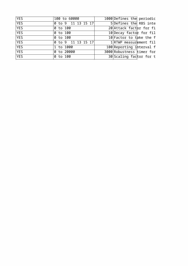
100 to 60000 1000 Defines the periodicity of the DL cell carrier power measurement reporting.Used by CellLoad Monitor Initialization in Admission Control.The configured value is divided by 10 by the RNC traffic application before it is sent on NBAP to RBS.This attribute may only be changed by Ericsson personnel. Disturbances:Changing this attribute may affect ongoing traffic.Unit: msResolution: 100Change takes effect: Re-initiation of Admission Control measurements0 to 9 11 13 15 17 19 5 Defines the RBS internal filtering.Used by CellLoad Monitor Initialization in Admission Control.This attribute may only be changed by Ericsson personnel. Disturbances:Changing this attribute may affect ongoing traffic.Change takes effect: Re-initiation of Admission Control measurements0 to 100 20 Attack factor for filtering the measured/estimated power consumption.Used by Cell Load Monitor in Admission Control.This attribute may only be changed by Ericsson personnel. Disturbances:Changing this attribute may affect ongoing traffic. Whenever its value is set, the cell is disabled automatically and then re-enabled.Change takes effect: Object disabled/enabledUnit: %0 to 100 10 Decay factor for filtering the measured/estimated power consumption.Used by Cell Load Monitor in Admission Control.This attribute may only be changed by Ericsson personnel. Unit: %Change takes effect: Immediately0 to 100 10 Factor to take the flexibility of the TFS for a DCH into account when calculating the ASE. This attribute may only be changed by Ericsson personnel. Disturbances:Changing this attribute may affect ongoing traffic. Whenever its value is set, the cell is disabled automatically and then re-enabled.Change takes effect: Object disabled/enabledUnit: 0.010 to 9 11 13 15 17 19 1 RTWP measurement filter coefficient.This attribute may only be changed by Ericsson personnel. Change takes effect: Re-initiation of UL RTWP measurements1 to 1000 100 Reporting interval for transmitted carrier power measurements between reports A and B.It is recommended to set this attribute to an integral multiple of txInterval (in ms).This attribute may only be changed by Ericsson personnel. Unit: 10 msFilter: TDD0 to 20000 3000 Robustness timer for end of congestion detection.Used by Congestion Control.This attribute may only be changed by Ericsson personnel. Unit: msFilter: TDD0 to 100 30 Scaling factor for the estimation of the DL power consumption per RL. Unit: 0.01Changing this attribute may affect ongoing traffic.This attribute may only be changed by Ericsson personnel. Filter: TDD
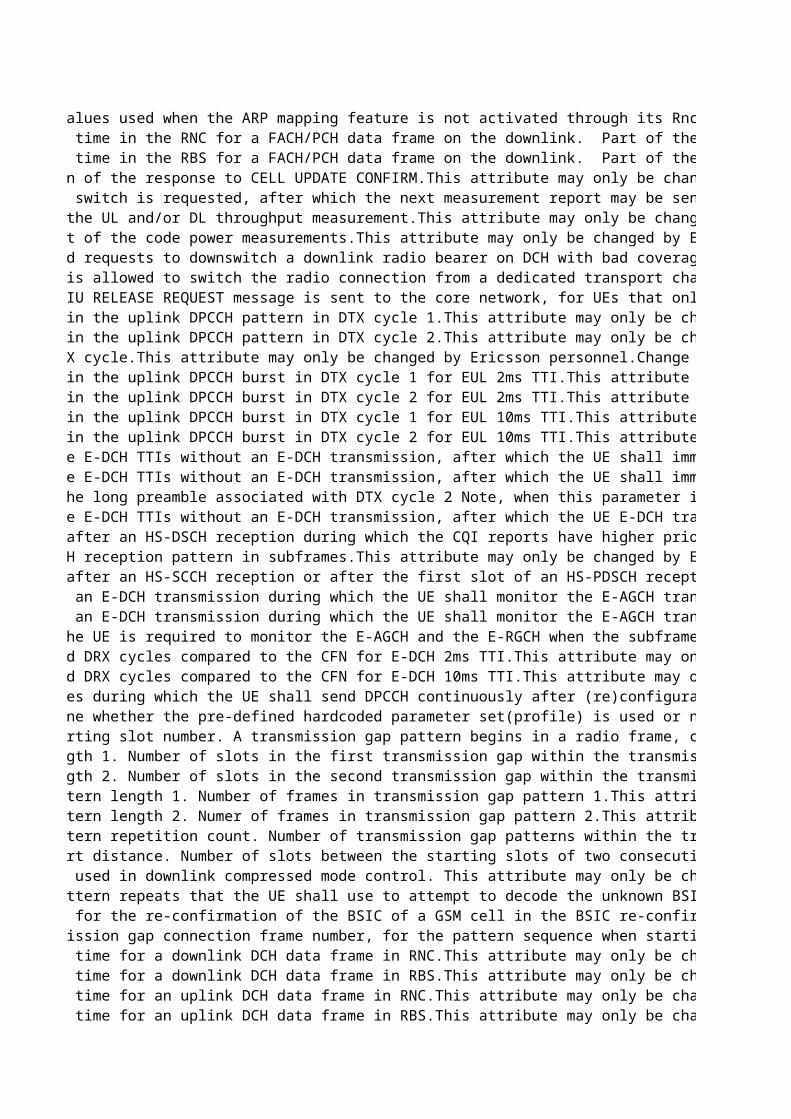
System default ARP values used when the ARP mapping feature is not activated through its RncFeature MO instance.This attribute may only be changed by Ericsson personnel. Dependencies:The values in this attribute are displayed in the read-only attribute systemDefaultArpQosFilter: FDDBuffering/processing time in the RNC for a FACH/PCH data frame on the downlink. Part of the Downlink Offset (DO). Should be set to the upper limit of the delay within the RNC in the transmission of each frame.The actual buffering/processing time is affected by the type of traffic frame (transport block type) as well as load, processing type, etc. If this value is set too low, frames may be lost or discarded (due to too-late arrival).This attribute may only be changed by Ericsson personnel. Unit: msBuffering/processing time in the RBS for a FACH/PCH data frame on the downlink. Part of the Downlink Offset (DO). Should be set to the upper limit of the delay within the RBS in the transmission of each frame.The actual buffering/processing time is affected by the type of traffic frame (transport block type) as well as load, processing type, etc. If this value is set too low, frames may be lost or discarded (due to "too late" arrival).This attribute may only be changed by Ericsson personnel. Unit: msTimer for supervision of the response to CELL UPDATE CONFIRM.This attribute may only be changed by Ericsson personnel.Unit: 0.1 sTime after a channel switch is requested, after which the next measurement report may be sent from either the UE or RNC internal buffer load measurements. Used to limit the UE and RNC buffer load reporting intensity.This attribute may only be changed by Ericsson personnel. Value mapping:0: 0.25 s1: 0.5 s2: 1 s3: 2 s4: 4 s5: 8 s6: 16 sChange takes effect: New connectionsAveraging period of the UL and/or DL throughput measurement.This attribute may only be changed by Ericsson personnel. Unit: 0.1 sChange takes effect: New connectionsFiltering coefficient of the code power measurements.This attribute may only be changed by Ericsson personnel. Change takes effect: New connectionsTime between repeated requests to downswitch a downlink radio bearer on DCH with bad coverage to a lower DCH rate.This attribute may only be changed by Ericsson personnel. Special values.0: the repeat timer not in use, meaning that a downswitch request will not be repeatedValue mapping:1: 50 ms...4: 200 ms...40: 2000msUnit: 50 msChange takes effect: New connectionsControls whether it is allowed to switch the radio connection from a dedicated transport channel to a common transport channel (RACH/FACH) during channel switching in case of radio bearer inactivity.This attribute may only be changed by Ericsson personnel. Value mapping:0: Transition to common channel (RACH/FACH) is not allowed1: Transition to common channel (RACH/FACH) is allowedChange takes effect: New connectionsTime after which an IU RELEASE REQUEST message is sent to the core network, for UEs that only use one or two signaling connections and no RABs in state CELL_DCH.This attribute may only be changed by Ericsson personnel. Special values:0: do not release (no need to start measurements or algorithm)Unit: sChange takes effect: New connectionsNumber of subframes in the uplink DPCCH pattern in DTX cycle 1.This attribute may only be changed by Ericsson personnel.Change takes effect: New connectionFilter: FDDNumber of subframes in the uplink DPCCH pattern in DTX cycle 2.This attribute may only be changed by Ericsson personnel.Change takes effect: New connectionFilter: FDDLength of the MAC DTX cycle.This attribute may only be changed by Ericsson personnel.Change takes effect: New connectionFilter: FDDNumber of subframes in the uplink DPCCH burst in DTX cycle 1 for EUL 2ms TTI.This attribute may only be changed by Ericsson personnel.Change takes effect: New connectionFilter: FDDNumber of subframes in the uplink DPCCH burst in DTX cycle 2 for EUL 2ms TTI.This attribute may only be changed by Ericsson personnel.Change takes effect: New connectionFilter: FDDNumber of subframes in the uplink DPCCH burst in DTX cycle 1 for EUL 10ms TTI.This attribute may only be changed by Ericsson personnel.Change takes effect: New connectionFilter: FDDNumber of subframes in the uplink DPCCH burst in DTX cycle 2 for EUL 10ms TTI.This attribute may only be changed by Ericsson personnel.Change takes effect: New connectionFilter: FDDNumber of consecutive E-DCH TTIs without an E-DCH transmission, after which the UE shall immediately move from DTX cycle 1 to DTX cycle 2, for EUL 2ms TTI .This attribute may only be changed by Ericsson personnel.Change takes effect: New connectionFilter: FDDNumber of consecutive E-DCH TTIs without an E-DCH transmission, after which the UE shall immediately move from DTX cycle 1 to DTX cycle 2, for EUL 10ms TTI.This attribute may only be changed by Ericsson personnel.Change takes effect: New connectionFilter: FDDNumber of slots in the long preamble associated with DTX cycle 2 Note, when this parameter is set to 2, RNC excludes the IE "UE DTX long preamble length" from the RRC message containing the IE DTX-DRX information.This attribute may only be changed by Ericsson personnel.Change takes effect: New connectionFilter: FDDNumber of consecutive E-DCH TTIs without an E-DCH transmission, after which the UE E-DCH transmissions are restricted to the MAC DTX pattern. The UE E-DCH transmissions are never restricted to the MAC DTX pattern when it is set to 0 (=infinity).This attribute may only be changed by Ericsson personnel.Change takes effect: New connectionFilter: FDDNumber of subframes after an HS-DSCH reception during which the CQI reports have higher priority than the DTX pattern The CQI reports always have higher priority than the DTX pattern when it is set to -1 (=infinity). This attribute may only be changed by Ericsson personnel.Change takes effect: New connectionFilter: FDDLength of the HS-SCCH reception pattern in subframes.This attribute may only be changed by Ericsson personnel.Change takes effect: New connectionFilter: FDDNumber of subframes after an HS-SCCH reception or after the first slot of an HS-PDSCH reception during which the UE shall monitor the HS-SCCHs in the UE's HS-SCCH set continuously.This attribute may only be changed by Ericsson personnel.Change takes effect: New connectionFilter: FDDNumber of TTIs after an E-DCH transmission during which the UE shall monitor the E-AGCH transmissions from the serving E-DCH cell and the E-RGCH from cells in the serving E-DCH radio link set, for EUL 2ms TTI.This attribute may only be changed by Ericsson personnel.Change takes effect: New connectionFilter: FDDNumber of TTIs after an E-DCH transmission during which the UE shall monitor the E-AGCH transmissions from the serving E-DCH cell and the E-RGCH from cells in the serving E-DCH radio link set, for EUL 10ms TTI.This attribute may only be changed by Ericsson personnel.Change takes effect: New connectionFilter: FDDDetermines whether the UE is required to monitor the E-AGCH and the E-RGCH when the subframe (2msTTI) or frame (10ms TTI) overlaps with the start of the DRX reception pattern.This attribute may only be changed by Ericsson personnel.Change takes effect: New connectionFilter: FDDOffset of the DTX and DRX cycles compared to the CFN for E-DCH 2ms TTI.This attribute may only be changed by Ericsson personnel.Change takes effect: New connectionFilter: FDDOffset of the DTX and DRX cycles compared to the CFN for E-DCH 10ms TTI.This attribute may only be changed by Ericsson personnel.Change takes effect: New connectionFilter: FDDNumber of radio frames during which the UE shall send DPCCH continuously after (re)configuration with CPC activated.This attribute may only be changed by Ericsson personnel.Change takes effect: New connectionFilter: FDDParameter to determine whether the pre-defined hardcoded parameter set(profile) is used or not to configure the CPC connections. If it is set to "OFF", the CPC connections are configured with a pre-defined hardcoded parameter set(CPC profile). If ON, the static configuration associated with the CPC profile is overridden by the values set for the parameters of the MO CPC.This attribute may only be changed by Ericsson personnel.Change takes effect: New connectionFilter: FDDTransmission gap starting slot number. A transmission gap pattern begins in a radio frame, containing at least one transmission gap slot. TGSN is the slot number of the first transmission gap slot within the first radio frame of the transmission gap pattern. This attribute may only be changed by Ericsson personnel. Change takes effect: Next configuration of the transmission gap pattern sequence in UE, DRNC or RBS.Transmission gap length 1. Number of slots in the first transmission gap within the transmission gap pattern. This attribute may only be changed by Ericsson personnel. Value mapping:Possible values for GSM carrier RSSI Measurement are 3, 4, 5, 7, 10, 14.Possible values for Initial BSIC identification are 7, 10, 14.Possible values for BSIC re-confirmation are 7, 10, 14.Possible values for Inter Frequency measurements are 7, 10, 14.Since the value ranges are different for each pattern sequence, the system will not check the range. It is the responsibility of the user (Ericsson personnel) to check the range when configuring the parameter. Change takes effect: Next configuration of the transmission gap pattern sequence in UE, DRNC or RBS.Transmission gap length 2. Number of slots in the second transmission gap within the transmission gap pattern. This attribute may only be changed by Ericsson personnel. Dependencies:If this parameter is not explicitly set by higher layers, then tGL2 = tGL1. Value mapping:Possible values for GSM carrier RSSI Measurement are 3, 4, 5, 7, 10, 14.Possible values for Initial BSIC identification are 7, 10, 14.Possible values for BSIC re-confirmation are 7, 10, 14.Possible values for Inter Frequency measurements are 7, 10, 14.Since the value ranges are different for each pattern sequence, the system will not check the range. It is the responsibility of the user (Ericsson personnel) to check the range when configuring the parameter. Change takes effect: Next configuration of the transmission gap pattern sequence in UE, DRNC or RBS.Transmission gap pattern length 1. Number of frames in transmission gap pattern 1.This attribute may only be changed by Ericsson personnel. Special values:Initial value (set by system) for GSM carrier RSSI Measurement ("CpmTransGapPattSeq=1") is 8.Initial value (set by system) for Initial BSIC identification ("CpmTransGapPattSeq=2") is 8.Initial value (set by system) for BSIC re-confirmation ("CpmTransGapPattSeq=3") is 8.Initial value (set by system) for Inter Frequency measurements ("CpmTransGapPattSeq=4") is 4.Value mapping:Possible value for GSM carrier RSSI Measurement is 8.Possible values for Initial BSIC identification are 3, 4, 8, 12, 24.Possible values for BSIC re-confirmation are 3, 4, 8, 12, 15, 23, 24.Possible values for Inter Frequency measurements are 3, 4, 8, 12, 24, 35.Since the value ranges are different for each pattern sequence, the system will only check that the value is within the full range defined for the parameter. There is no check that a value for a specific sequence is within the range for that sequence. For example, the value 23 will be accepted for Initial BSIC identification. It is the responsibility of the user (Ericsson personnel) to check that the value for a specific sequence is within the range of that sequence when configuring the parameter. Change takes effect: Next configuration of the transmission gap pattern sequence in UE, DRNC or RBS.Transmission gap pattern length 2. Numer of frames in transmission gap pattern 2.This attribute may only be changed by Ericsson personnel. Special values:Initial value (set by system) for GSM carrier RSSI Measurement ("CpmTransGapPattSeq=1") is 8.Initial value (set by system) for Initial BSIC identification ("CpmTransGapPattSeq=2") is 8.Initial value (set by system) for BSIC re-confirmation ("CpmTransGapPattSeq=3") is 8.Initial value (set by system) for Inter Frequency measurements ("CpmTransGapPattSeq=4") is 4.Dependencies:It is up to the user (Ericsson personnel) to make sure tGLP1 = tGPL2 for subsequent changes during operation. There is no check in the code for this.Value mapping:Possible value for GSM carrier RSSI Measurement is 8.Possible values for Initial BSIC identification are 3, 4, 8, 12, 24.Possible values for BSIC re-confirmation are 3, 4, 8, 12, 15, 23, 24.Possible values for Inter Frequency measurements are 3, 4, 8, 12, 24, 35.Since the value ranges are different for each pattern sequence, the system will only check that the value is within the full range defined for the parameter. There is no check that a value for a specific sequence is within the range for that sequence. For example, the value 23 will be accepted for Initial BSIC identification. It is the responsibility of the user (Ericsson personnel) to check that the value for a specific sequence is within the range of that sequence when configuring the parameter. Change takes effect: Next configuration of the transmission gap pattern sequence in UE, DRNC or RBS.Transmission gap pattern repetition count. Number of transmission gap patterns within the transmission gap pattern sequence. This attribute may only be changed by Ericsson personnel. Special values:0 means infinity. Change takes effect: Next configuration of the transmission gap pattern sequence in UE, DRNC or RBS.Transmission gap start distance. Number of slots between the starting slots of two consecutive transmission gaps within a transmission gap pattern. If this parameter is not set by higher layers, then there is only one transmission gap in the transmission gap pattern. If there is only one transmission gap in the transmission gap pattern, this parameter shall be set to 0.This attribute may only be changed by Ericsson personnel. Special values:0 means undefinedChange takes effect: Next configuration of the transmission gap pattern sequence in UE, DRNC or RBS.Frame structure type used in downlink compressed mode control. This attribute may only be changed by Ericsson personnel. Value mapping:0 = 'A'1 = 'B' Change takes effect: Next configuration of the transmission gap pattern sequence in UE, DRNC or RBS.Maximum number of pattern repeats that the UE shall use to attempt to decode the unknown BSIC of a GSM cell in the initial BSIC identification procedure.This attribute may only be changed by Ericsson personnel. Change takes effect: Next configuration of the transmission gap pattern sequence in UE, DRNC or RBS.Maximum time allowed for the re-confirmation of the BSIC of a GSM cell in the BSIC re-confirmation procedure.This attribute may only be changed by Ericsson personnel. Value mapping:1: 0.5 s2: 1.0 s3: 1.5 s...11: 5.5 s...20: 10.0 sUnit: 0.5 sChange takes effect: Next configuration of the transmission gap pattern sequence in UE, DRNC or RBS.Offset to the transmission gap connection frame number, for the pattern sequence when starting CPM.TGCFN = running CFN + startCFNoffset + TGCFNoffsetThis attribute may only be changed by Ericsson personnel. Special values:Initial value (set by system) for GSM carrier RSSI measurement ("CpmTransGapPattSeq=1") is 0.Initial value (set by system) for Initial BSIC identification ("CpmTransGapPattSeq=2") is 2.Initial value (set by system) for BSIC reconfirmation ("CpmTransGapPattSeq=3") is 6.Initial value (set by system) for Inter Frequency measurements ("CpmTransGapPattSeq=4") is 0.Change takes effect: Next configuration of the transmission gap pattern sequence in UE, DRNC or RBS.Buffering/processing time for a downlink DCH data frame in RNC.This attribute may only be changed by Ericsson personnel. Unit: msBuffering/processing time for a downlink DCH data frame in RBS.This attribute may only be changed by Ericsson personnel. Unit: msBuffering/processing time for an uplink DCH data frame in RNC.This attribute may only be changed by Ericsson personnel. Dependencies:It is recommended to set tProcRncUl + toAWEUl + toAEUl <= 640 [ms] It is recommended to set toAWSUl <= toAEUlUnit: msBuffering/processing time for an uplink DCH data frame in RBS.This attribute may only be changed by Ericsson personnel. Unit: ms
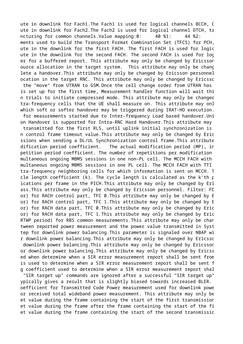
Rate matching attribute in downlink for Fach1.The Fach1 is used for logical channels BCCH, CCCH and DCCH, control signaling.This attribute may only be changed by Ericsson personnel. Disturbances:Changing this attribute may affect ongoing traffic.Filter: FDDRate matching attribute in downlink for Fach2.The Fach2 is used for logical channel DTCH, traffic signaling.This attribute may only be changed by Ericsson personnel. Disturbances:Changing this attribute may affect ongoing traffic.Filter: FDDMaximum amount of puncturing for common channels.Value mapping:0: 40 %1: 44 %2: 48 %...15: 100 %This attribute may only be changed by Ericsson personnel.Dependencies:Before changing this attribute, check if tfcs needs to be changed as well. If so, lock the parent UtranCell manually before changing both.Disturbances:Changing this attribute may affect ongoing traffic.Unit: 4 %Filter: TDDReplaces: tdSccpchPunctureLimitConfiguration of elements used to build the Transport Format Combination Set (TFCS) for PCH, FACH1 and FACH2.This attribute may only be changed by Ericsson personnel.Disturbances:Changing this attribute may affect ongoing traffic.Filter: TDDReplaces: tdTfcsRate matching attribute in the downlink for the first FACH. The first FACH is used for logical channels BCCH, CCCH and DCCH, for control signaling.This attribute may only be changed by Ericsson personnel. Disturbances:Changing this attribute may affect ongoing traffic.Dependencies:Before changing this attribute, check if tfcs needs to be changed as well. If so, lock the parent UtranCell manually before changing both. Filter: TDDRate matching attribute in the downlink for the second FACH. The second FACH is used for logical channel DTCH, for traffic signaling.This attribute may only be changed by Ericsson personnel. Disturbances:Changing this attribute may affect ongoing traffic.Dependencies:Before changing this attribute, check if tfcs needs to be changed as well. If so, lock the parent UtranCell manually before changing both.Filter: TDDMaximum time in buffer for a buffered report. This attribute may only be changed by Ericsson personnel. Value mapping:0: 0 s1: 0.2 s2: 0.4 s3: 0.6 s4: 0.8 s5: 1.0 s...50: 10 sUnit: 0.2 sChange takes effect: Ongoing connections (next switch to CELL_DCH)Maximum time for resource allocation in the target system. This attribute may only be changed by Ericsson personnel. Unit: sChange takes effect: New connectionsMaximum time to complete a handover.This attribute may only be changed by Ericsson personnel. Unit: sChange takes effect: New connectionsMaximum time for relocation in the target RNC. This attribute may only be changed by Ericsson personnel. Unit: sChange takes effect: New connectionsTime for supervising the "move" from UTRAN to GSM.Once the cell change order from UTRAN has been sent, the system expects to receive an Iu release command or Cell change failure from UTRAN within this amount of time.This attribute may only be changed by Ericsson personnel. Unit: sChange takes effect: New connectionsWhen the connection is set up for the first time, Measurement handler function will wait this predetermined time before it sends the first cell list to the UE. This extra delay will decrease the risk for the UE not to get the initial cell list , since initially it is busy to get synchronized to UTRAN.This attribute may only be changed by Ericsson personnel. Unit: sChange takes effect: Ongoing connectionsTime interval between trials to initiate compressed mode. This attribute may only be changed by Ericsson personnel. Special values:0 means no retry. Value mapping:0: 0.0 s1: 0.2 s2: 0.4 s3: 0.6 s4: 0.8 s5: 1.0 s...50: 10 sUnit: 0.2 sChange takes effect: Ongoing connections (next switch to CELL_DCH)Filter: FDDMaximum number of intra-frequency cells that the UE shall measure on. This attribute may only be changed by Ericsson personnel. Change takes effect: Ongoing connectionsMaximum time during which soft or softer handover may be triggered during IRAT-HO execution.This attribute may only be changed by Ericsson personnel. Value mapping:1: 0.5 s2: 1.0 s...10: 5.0 sUnit: 0.5 sChange takes effect: New connectionsTime for Supervision for measurements started due to Inter-frequency Load based handover.Unit: SecondsChange takes effect: Next soft congestionThis attribute may only be changed by Ericsson personnel. Filter: FDDControls whether Baton Handover is supported for Intra-RNC Hard Handover.This attribute may only be changed by Ericsson personnel. Filter: TDDReplaces: tdBatonHoSupportDownlink TPC pattern transmitted for the first RLS, until uplink initial synchronization is achieved. This parameter is used for the NBAP cell setup message.This attribute may only be changed by Ericsson personnel. Dependencies: Changing this attribute may affect ongoing traffic.DL/UL Synchronization control frame timeout value.This attribute may only be changed by Ericsson personnel. Unit: 100 msNumber of re-transmissions when sending a DL/UL Synchronization control frame.This attribute may only be changed by Ericsson personnel. Represents m, the modification period coefficient. The actual modification period (MP), in number of frames, equals 2^m.m >= k, where k = max[cnDrxCycleLengthPs, cnDrxCycleLengthCs, utranDrxCycleLength] To allow the UE to measure, when applicable, on another frequency when reading MCCH there has to be some gaps in the MCCH transmission (the MP shall not be fully utilized). Note: The UE and SGSN can negotiate the value of the cnDrxCycleLengthPs. This case can not be handled by the system. This attribute may only be changed by Ericsson personnel.Change takes effect: At MbmsCch lock/unlock and at system restartRepresents r, the repetition period coefficient. The number of repetitions per modification period equals 2^r while the actual repetition period, in number of frames, equals [2^m DIV 2^r], where m is the modification period coefficient.[2^m DIV 2^r] >= nrOfRrcFrames, where nrOfRrcFrames defines the number of frames the MCCH information requires in each Repetition Period. (Note: nrOfRrcFrames is not a parameter but only a definition in the above equation.)This attribute may only be changed by Ericsson personnel.Change takes effect: At MbmsCch lock/unlock and at system restartMaximum number of simultaneous ongoing MBMS sessions in one non-PL cell. The MCCH FACH with TTI 20 ms for S-CCPCH has maximum user data rate 7.6 kbps.The values of the mbmsModificationPeriodCoeff (m) and mbmsRepetitionPeriodCoeff (r) have dependencies to the number of frames that can be scheduled per Repetition Period on MCCH with the data rate 7.6 kbps. Parameters nonPlSessionsMax, plSessionsMax and neighbourCellsMax put limits on number of frames to be scheduled in a worst case scenario.It must be considered when changing any of the above parameters that the number of frames to be scheduled on MCCH for RRC messages does not exceed the number of frames that can be scheduled per Repetition Period on MCCH.This attribute may only be changed by Ericsson personnel.Change takes effect: At MbmsCch lock/unlock and at system restartFilter: FDDMaximum number of simultaneous ongoing MBMS sessions in one PL cell. The MCCH FACH with TTI 20 ms for S-CCPCH has maximum user data rate 7.6 kbps.The values of the mbmsModificationPeriodCoeff (m) and mbmsRepetitionPeriodCoeff (r) have dependencies to the number of frames that can be scheduled per Repetition Period on MCCH with the data rate 7.6 kbps. Parameters nonPlSessionsMax, plSessionsMax and neighbourCellsMax put limits on number of frames to be scheduled in a worst case scenario.It must be considered when changing any of the above parameters that the number of frames to be scheduled on MCCH for RRC messages does not exceed the number of frames that can be scheduled per Repetition Period on MCCH.This attribute may only be changed by Ericsson personnel.Change takes effect: At MbmsCch lock/unlock and at system restartMaximum number of intra-frequency neighboring cells for which information is sent on MCCH. The MCCH FACH with TTI 20 ms for S-CCPCH has maximum user data rate 7.6 kbps.The values of the mbmsModificationPeriodCoeff (m) and mbmsRepetitionPeriodCoeff (r) have dependencies to the number of frames that can be scheduled per Repetition Period on MCCH with the data rate 7.6 kbps. Parameters nonPlSessionsMax, plSessionsMax and neighbourCellsMax put limits on number of frames to be scheduled in a worst case scenario.It must be considered when changing any of the above parameters that the number of frames to be scheduled on MCCH for RRC messages does not exceed the number of frames that can be scheduled per Repetition Period on MCCH.This attribute may only be changed by Ericsson personnel.Change takes effect: At MbmsCch lock/unlock and at system restartBCCH modification cycle length coefficient (k). The cycle length is calculated as the k'th potential of 2, where k = 6,..,9. The BCCH modification information element should be transmitted in every frame within a defined interval. This interval will be within a specific cycle interval similarly defined as DRX cycle length.Special values:Initially set by the system to 9 (corresponds to cycle length 5,120 s).This attribute may only be changed by Ericsson personnel. Number of paging indications per frame in the PICH.This attribute may only be changed by Ericsson personnel. Disturbances:Changing this attribute may affect ongoing traffic.Filter: FDDID of the service class.This attribute may only be changed by Ericsson personnel. Filter: FDDBeta value (gainFactor) for RACH control part, TFC 0.This attribute may only be changed by Ericsson personnel. Disturbances:Changing this attribute may affect ongoing traffic.Change takes effect: New connectionsFilter: FDDBeta value (gainFactor) for RACH control part, TFC 1.This attribute may only be changed by Ericsson personnel. Disturbances:Changing this attribute may affect ongoing traffic.Change takes effect: New connectionsFilter: FDDBeta value (gainFactor) for RACH data part, TFC 0.This attribute may only be changed by Ericsson personnel. Disturbances:Changing this attribute may affect ongoing traffic.Change takes effect: New connectionsBeta value (gainFactor) for RACH data part, TFC 1.This attribute may only be changed by Ericsson personnel. Disturbances:Changing this attribute may affect ongoing traffic.Change takes effect: New connectionsFilter: FDDReport periodicity (RTWP period) for RBS common measurements.This attribute may only be changed by Ericsson personnel. Disturbances:Changing this attribute may affect ongoing traffic.Unit: 10 msChange takes effect: New connectionsIf the difference between reported power measurement and the power value transmitted in System Information is larger than this hysteresis in one cell, an update of system information is initiated in that cell.This attribute may only be changed by Ericsson personnel. Value mapping:30: 3.0 dB31: 3.1 dB...60: 6.0 dBUnit: 0.1 dBFilter: FDDMaximum adjustment step for downlink power balancing.This parameter is signaled over NBAP with the values [1..10] slots, where 1 corresponds to an allowed change of the downlink power (due to downlink power balancing) of at most 1 dB every 1 slot. 10 corresponds to an allowed change of the downlink power of at most 1 dB every 10 slots.maxAdjustmentStep = 1 corresponds to a limit on rate of change of 1 dB/slot.maxAdjustmentStep = 10 corresponds to a limit on rate of change of 0.1 dB/slot.This attribute may only be changed by Ericsson personnel. Change takes effect: New connectionsFilter: FDDAdjustment period for downlink power balancing.This attribute may only be changed by Ericsson personnel. Change takes effect: New connectionsFilter: FDDAdjustment ratio for downlink power balancing.This attribute may only be changed by Ericsson personnel. Change takes effect: New connectionsFilter: FDDMeasurement period for downlink power balancing.This attribute may only be changed by Ericsson personnel. Unit: 10 msChange takes effect: New connectionsFilter: FDDDefines the range used when determine when a SIR error measurement report shall be sent from the RBS to RNC.This attribute may only be changed by Ericsson personnel. Unit: dBChange takes effect: New connectionsFilter: FDDDefines the hysteresis used to determine when a SIR error measurement report shall be sent from the RBS to RNC.This attribute may only be changed by Ericsson personnel. Resolution: 10Unit: msChange takes effect: New connectionsFilter: FDDMeasurement filtering coefficient used to determine when a SIR error measurement report shall be sent from the RBS to RNC.This attribute may only be changed by Ericsson personnel. Change takes effect: New connectionsFilter: FDDTime that subsequent "SIR target up" commands are ignored after a successful "SIR target up" command, for 10 ms TTI users.This attribute may only be changed by Ericsson personnel. Unit: radio frame (10 ms)Change takes effect: New connectionsThe jump algorithm typically gives a result that is slightly biased towards increased BLER. This parameter is used to compensate for this bias.This attribute may only be changed by Ericsson personnel. Value mapping: 1: 0,1 2: 0,2...10: 1,0Change takes effect: New connectionsMeasurement Filter Coefficient for Transmitted Code Power measurement used for downlink power balancing.This attribute may only be changed by Ericsson personnel. Dependencies: Changing this attribute may affect traffic.Change takes effect: New connectionsFilter: FDDFilter coefficient for received total wideband power measurement. This attribute may only be changed by Ericsson personnel. Change takes effect: New connectionsDelta in UL SIR target value during the frame containing the start of the first transmission gap in the transmission gap pattern. This attribute may only be changed by Ericsson personnel. Unit: 0.1 dBChange takes effect: New connectionsFilter: FDDDelta in UL SIR target value during the frame after the frame containing the start of the first transmission gap in the transmission gap pattern.This attribute may only be changed by Ericsson personnel. Unit: 0.1 dBChange takes effect: New connectionsFilter: FDDDelta in UL SIR target value during the frame containing the start of the second transmission gap in the transmission gap pattern. This attribute may only be changed by Ericsson personnel. Unit: 0.1 dBChange takes effect: New connectionsFilter: FDD
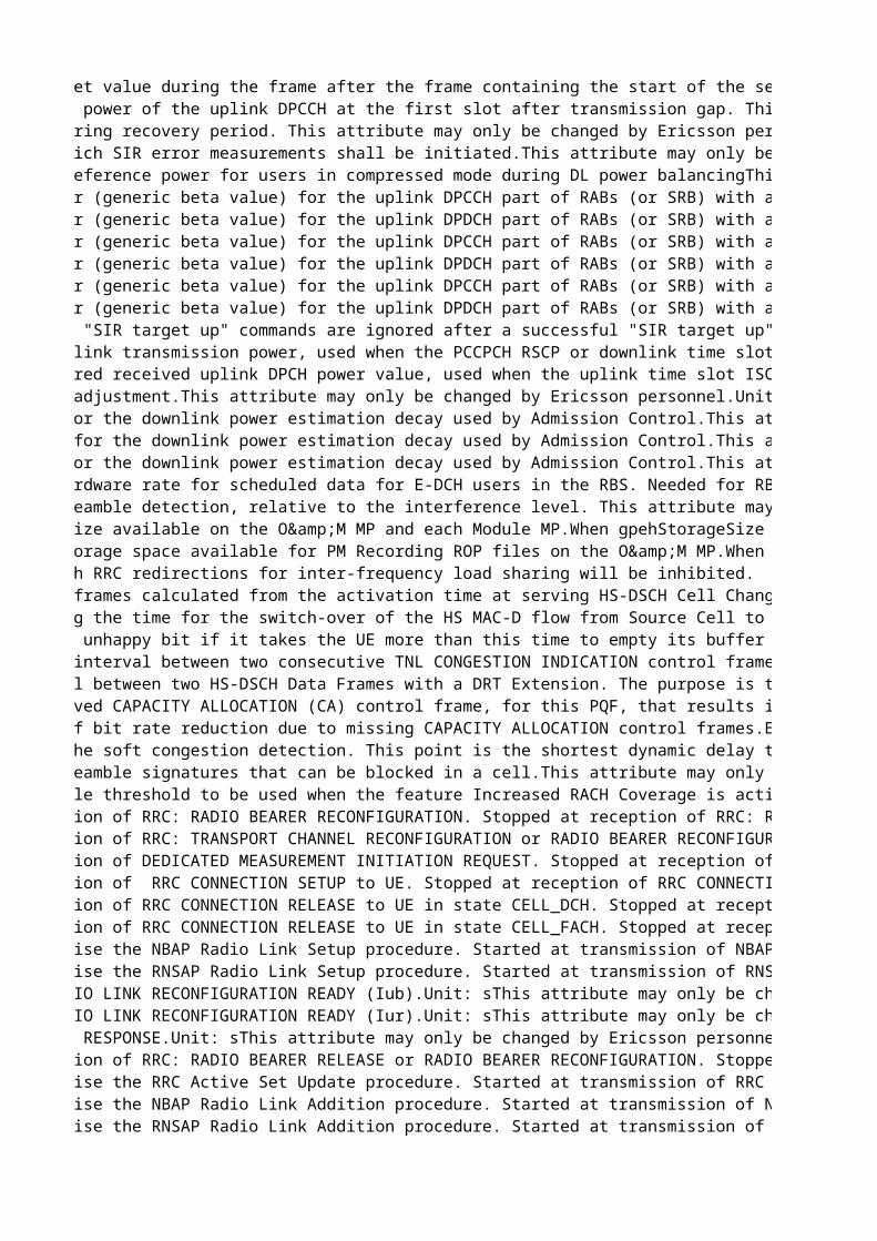
Delta in UL SIR target value during the frame after the frame containing the start of the second transmission gap in the transmission gap pattern.This attribute may only be changed by Ericsson personnel. Unit: 0.1 dBChange takes effect: New connectionsFilter: FDDMode of transmission power of the uplink DPCCH at the first slot after transmission gap. This attribute may only be changed by Ericsson personnel. Change takes effect: New connectionsFilter: FDDMode of step size during recovery period. This attribute may only be changed by Ericsson personnel. Change takes effect: New connectionsUsed to determine which SIR error measurements shall be initiated.This attribute may only be changed by Ericsson personnel. Value mapping:0: None1: Event E2: Event F3: Both (1&2)Filter: FDDUsed to adjust the reference power for users in compressed mode during DL power balancingThis attribute may only be changed by Ericsson personnel. Value mapping:0: 0.0 dB...4: 2.0 dB...20: 10.0 dBUnit: 0.5 dBFilter: FDDReference gain factor (generic beta value) for the uplink DPCCH part of RABs (or SRB) with a minimum spreading factor >= 32. 'Low' refers to low data transmission capability due to high spreading factor.Used by Power Control.This attribute may only be changed by Ericsson personnel. Dependencies:Note that either gainFactorCLow or gainFactorDLow must be equal to 15.Filter: FDDReference gain factor (generic beta value) for the uplink DPDCH part of RABs (or SRB) with a minimum spreading factor >= 32. 'Low' refers to low data transmission capability due to high spreading factor.Used by Power Control.This attribute may only be changed by Ericsson personnel. Dependencies:Note that either gainFactorCLow or gainFactorDLow must be equal to 15.Reference gain factor (generic beta value) for the uplink DPCCH part of RABs (or SRB) with a minimum spreading factor in the range 8 < SF <= 16. 'High' refers to high data transmission capability due to low spreading factor.Used by Power Control.This attribute may only be changed by Ericsson personnel. Dependencies:Note that either gainFactorCHigh or gainFactorDHigh must be equal to 15.Filter: FDDReference gain factor (generic beta value) for the uplink DPDCH part of RABs (or SRB) with a minimum spreading factor in the range 8 < SF <= 16. 'High' refers to high data transmission capability due to low spreading factor.Used by Power Control.This attribute may only be changed by Ericsson personnel. Dependencies:Note that either gainFactorCHigh or gainFactorDHigh must be equal to 15.Reference gain factor (generic beta value) for the uplink DPCCH part of RABs (or SRB) with a minimum spreading factor <= 8. 'Extra high' refers to extra high data transmission capability due to very low spreading factor. Used by Power Control.This attribute may only be changed by Ericsson personnel. Dependencies:gainFactorCExtraHigh or gainFactorDExtraHigh must be equal to 15Reference gain factor (generic beta value) for the uplink DPDCH part of RABs (or SRB) with a minimum spreading factor <= 8. 'Extra high' refers to extra high data transmission capability due to very low spreading factor. Used by Power Control.This attribute may only be changed by Ericsson personnel. Dependencies:gainFactorCExtraHigh or gainFactorDExtraHigh must be equal to 15Filter: FDDTime that subsequent "SIR target up" commands are ignored after a successful "SIR target up" command, for 2 ms TTI users.This attribute may only be changed by Ericsson personnel. Unit: radio frame (10 ms)Filter: FDDDefault initial downlink transmission power, used when the PCCPCH RSCP or downlink time slot ISCP is not received from the measurement report. Expressed relative to the value of UtranCell::pccpchPower.This attribute may only be changed by Ericsson personnel.Unit: 0.1 dBFilter: TDDReplaces: tdDefaultInitDlTransPowerDefault initial desired received uplink DPCH power value, used when the uplink time slot ISCP is not received from the measurement report. In the RRC CONNECTION SETUP message, the value of this attribute is used for the parameter ul-TargetSIR.This attribute may only be changed by Ericsson personnel.Unit: dBmFilter: TDDReplaces: tdDefaultPrxDpchDesStep size for power adjustment.This attribute may only be changed by Ericsson personnel.Unit: dBFilter: TDDReplaces: tdTddTpcStepSizeFirst decay factor for the downlink power estimation decay used by Admission Control.This attribute may only be changed by Ericsson personnel. Unit: %Filter: TDDSecond decay factor for the downlink power estimation decay used by Admission Control.This attribute may only be changed by Ericsson personnel. Unit: %Filter: TDDThird decay factor for the downlink power estimation decay used by Admission Control.This attribute may only be changed by Ericsson personnel. Unit: %Filter: TDDThe pre-allocated hardware rate for scheduled data for E-DCH users in the RBS. Needed for RBS hardware consumption calculations in RNC. The calculation is performed in the same way for 2 ms and 10 ms TTI, with this constant as input, but the values shall then be rounded up differently depending on the used TTI. This attribute may only be changed by Ericsson personnel. Dependencies: The same constant is defined in the RBS for the scheduler. These constants should be set to the same value. Unit: kbps (1000 bits per second)Resolution: 32Change takes effect: Ongoing connectionsFilter: FDDThe threshold for preamble detection, relative to the interference level. This attribute may only be changed by Ericsson personnel. Value mapping: 0: -36.0 dB 1: -35.5 dB...34: -19.0 dB...72: 0.0 dBDisturbances:Changing this attribute may affect ongoing traffic.Unit: 0.5 dBFilter: FDDTotal GPEH storage size available on the O&M MP and each Module MP.When gpehStorageSize is exceeded, the GPEH function will remove the oldest GPEH file(s) from the persistent storage to make space for a new file, and GPEH recording will continue.This attribute may only be changed by Ericsson personnel.Dependencies: The size of the GPEH file may never exceed the available GPEH storage size on each MP (gpehStorageSize >= gpehFileSize).Unit: kB (1000 bytes)Change takes affect: Next ROPTotal size of the storage space available for PM Recording ROP files on the O&M MP.When recordingStorageSize is reached, the PM Recording function will remove the oldest recording file and continue. If the recordingStorageSize is completely used by a single recording file, the PM Recording function will stop the recording until the next ROP begins.This attribute may only be changed by Ericsson personnel. Dependencies: The file sizes for UETR and CTR recordings may never exceed the available recording storage size on the central O&M MP: recordingStorageSize >= ctrFileSize, recordingStorageSize >= uetrFileSizeUnit: kB (1000 bytes)Change takes effect: Next ROPThreshold below which RRC redirections for inter-frequency load sharing will be inhibited. Defined in terms of the difference in available resources between the source cell and the target cell. This attribute may only be changed by Ericsson personnel. Unit: %Change takes effect: ImmediatelyOffset in number of frames calculated from the activation time at serving HS-DSCH Cell Change.This attribute may only be changed by Ericsson personnel. Dependencies:hsCellChangeCfnOffset >= hsMacdSwitchTimeOffsetFilter: FDDUsed when calculating the time for the switch-over of the HS MAC-D flow from Source Cell to Target Cell, at Serving HS-DSCH Cell Change.This attribute may only be changed by Ericsson personnel. Dependencies:hsMacdSwitchTimeOffset <= hsCellChangeCfnOffsetUnit: frameThe UE shall send an unhappy bit if it takes the UE more than this time to empty its buffer with the current serving grant.This attribute may only be changed by Ericsson personnel.Unit: msDefines the minimum interval between two consecutive TNL CONGESTION INDICATION control frames, belonging to one flow controlled EUL flow, which are sent towards RBS. The interval is valid per flow controlled flow, regardless of which type of TCI that are sent, e.g. with code 2 or 3. This attribute may only be changed by Ericsson personnel. Unit: msResolution: 50Minimum time interval between two HS-DSCH Data Frames with a DRT Extension. The purpose is to not send DRT Extensions too often. When the parameter is set to zero, no DRT Extensions are sent (the feature is turned OFF). This attribute may only be changed by Ericsson personnel. Unit: msResolution: 10Change takes effect: New connectionsTime without a received CAPACITY ALLOCATION (CA) control frame, for this PQF, that results in a reduced HSDPA bit rate. The reason for checking the presence of these CAPACITY ALLOCATION control frames in RNC is that a CA shall be received at least every one second time interval (more often or once per second). If this doesn't happen, it is likely that a CA is dropped over the transport network. Further on, if several CA control frames are dropped, not received in RNC, it could mean that the best effort type of transport network is congested. This attribute may only be changed by Ericsson personnel. Special values:0 defines that CA presence supervision is turned off.Unit: 0.1 sChange takes effect: New connectionsDefines the degree of bit rate reduction due to missing CAPACITY ALLOCATION control frames.Example: New bit rate = Old bit rate * (1- hsMissingCaReduction/100). This attribute may only be changed by Ericsson personnel. Unit: %Change takes effect: New connectionsStarting point for the soft congestion detection. This point is the shortest dynamic delay that can be detected as soft congestion, expressed as percentage of edchDataFrameDelayThresholdThis attribute may only be changed by Ericsson personnel. Unit: %Maximum number of preamble signatures that can be blocked in a cell.This attribute may only be changed by Ericsson personnel. Change takes effect: ImmediatelyFilter: FDDIndicates the preamble threshold to be used when the feature Increased RACH Coverage is active.This attribute may only be changed by Ericsson personnel. Value mapping:-360: -36.0 dB-355: -35.5 dB... -190: -19.0 dB... -5: -0.5 dB0: 0 dBUnit: 0.1 dBResolution: 5Change takes effect: ImmediatelyFilter: FDDStarted at transmission of RRC: RADIO BEARER RECONFIGURATION. Stopped at reception of RRC: RADIO BEARER RECONFIGURATION COMPLETE.Unit: sThis attribute may only be changed by Ericsson personnel. Started at transmission of RRC: TRANSPORT CHANNEL RECONFIGURATION or RADIO BEARER RECONFIGURATION. Stopped at reception of RRC: TRANSPORT CHANNEL RECONFIGURATION COMPLETE or RADIO BEARER RECONFIGURATION COMPLETE.Unit: sThis attribute may only be changed by Ericsson personnel. Started at transmission of DEDICATED MEASUREMENT INITIATION REQUEST. Stopped at reception of DEDICATED MEASUREMENT INITIATION RESPONSE.Unit: sThis attribute may only be changed by Ericsson personnel. Started at transmission of RRC CONNECTION SETUP to UE. Stopped at reception of RRC CONNECTION SETUP COMPLETE.Unit: sThis attribute may only be changed by Ericsson personnel. Started at transmission of RRC CONNECTION RELEASE to UE in state CELL_DCH. Stopped at reception of RRC CONNECTION RELEASE COMPLETE.Unit: sThis attribute may only be changed by Ericsson personnel. Started at transmission of RRC CONNECTION RELEASE to UE in state CELL_FACH. Stopped at reception of RRC CONNECTION RELEASE COMPLETE.Unit: sThis attribute may only be changed by Ericsson personnel. Timer used to supervise the NBAP Radio Link Setup procedure. Started at transmission of NBAP RADIO LINK SETUP REQUEST. Stopped at reception of NBAP RADIO LINK SETUP RESPONSE.Unit: sThis attribute may only be changed by Ericsson personnel. Timer used to supervise the RNSAP Radio Link Setup procedure. Started at transmission of RNSAP RADIO LINK SETUP REQUEST. Stopped at reception of RNSAP RADIO LINK SETUP RESPONSE.Unit: sThis attribute may only be changed by Ericsson personnel. Waiting time for RADIO LINK RECONFIGURATION READY (Iub).Unit: sThis attribute may only be changed by Ericsson personnel. Waiting time for RADIO LINK RECONFIGURATION READY (Iur).Unit: sThis attribute may only be changed by Ericsson personnel. Waiting time for RRC RESPONSE.Unit: sThis attribute may only be changed by Ericsson personnel. Started at transmission of RRC: RADIO BEARER RELEASE or RADIO BEARER RECONFIGURATION. Stopped at reception of RRC: RADIO BEARER RELEASE COMPLETE or RADIO BEARER RECONFIGURATION COMPLETE.Unit: sThis attribute may only be changed by Ericsson personnel. Timer used to supervise the RRC Active Set Update procedure. Started at transmission of RRC ACTIVE SET UPDATE REQUEST. Stopped at reception of RRC ACTIVE SET UPDATE COMPLETE or RRC ACTIVE SET UPDATE FAILURE.Unit: sThis attribute may only be changed by Ericsson personnel. Timer used to supervise the NBAP Radio Link Addition procedure. Started at transmission of NBAP RADIO LINK ADDITION REQUEST. Stopped at reception of NBAP RADIO LINK ADDITION RESPONSE or NBAP RADIO LINK ADDITION FAILURE or NBAP ERROR INDICATION.Unit: sThis attribute may only be changed by Ericsson personnel. Timer used to supervise the RNSAP Radio Link Addition procedure. Started at transmission of RNSAP RADIO LINK ADDITION REQUEST. Stopped at reception of RNSAP RADIO LINK ADDITION RESPONSE or RNSAP RADIO LINK ADDITION FAILURE or RNSAP ERROR INDICATION.Unit: sThis attribute may only be changed by Ericsson personnel.
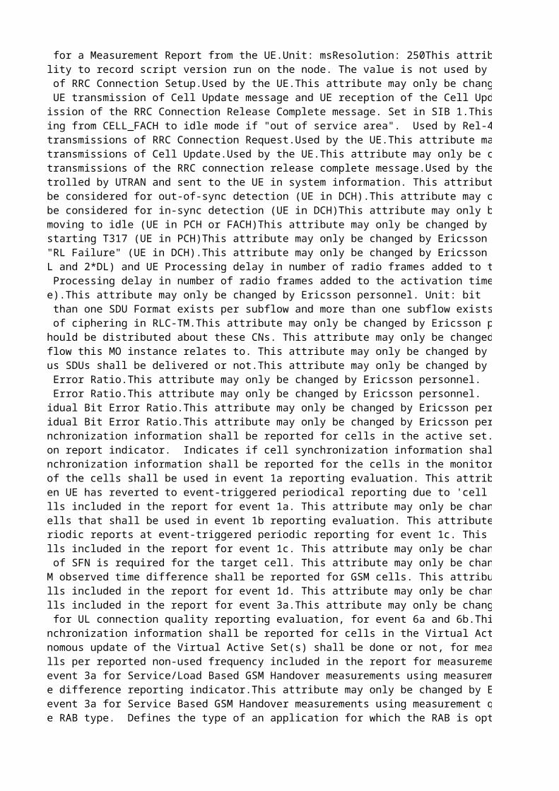
Maximum waiting time for a Measurement Report from the UE.Unit: msResolution: 250This attribute may only be changed by Ericsson personnel. Provides the possibility to record script version run on the node. The value is not used by the RNC.This attribute may only be changed by Ericsson personnel. Time for supervision of RRC Connection Setup.Used by the UE.This attribute may only be changed by Ericsson personnel. Value mapping:0: 100 ms1: 200 ms2: 400 ms3: 600 ms4: 800 ms5: 1000 ms6: 1200 ms7: 1400 ms8: 1600 ms9: 1800 ms10: 2000 ms11: 3000 ms12: 4000 ms13: 6000 ms14: 8000 msChange takes effect: New connectionsMaximum time between UE transmission of Cell Update message and UE reception of the Cell Update Confirm message. If not received, the UE sends a new Cell Update. This attribute may only be changed by Ericsson personnel. 0: 100 ms1: 200 ms2: 400 ms3: 600 ms4: 800 ms5: 1000 ms6: 1200 ms7: 1400 ms8: 1600 ms9: 1800 ms10: 2000 ms11: 3000 ms12: 4000 ms13: 6000 ms14: 8000 msStarted at UE transmission of the RRC Connection Release Complete message. Set in SIB 1.This attribute may only be changed by Ericsson personnel. Change takes effect: New connectionsMaximum time for moving from CELL_FACH to idle mode if "out of service area". Used by Rel-4 and earlier UEs. Rel-5 and later UEs will ignore the value of this attribute.This attribute may only be changed by Ericsson personnel. Unit: sMaximum number of retransmissions of RRC Connection Request.Used by the UE.This attribute may only be changed by Ericsson personnel. Change takes effect: New connectionsMaximum number of retransmissions of Cell Update.Used by the UE.This attribute may only be changed by Ericsson personnel. Maximum number of retransmissions of the RRC connection release complete message.Used by the UE. This attribute may only be changed by Ericsson personnel. Change takes effect: New connectionsUE timer that is controlled by UTRAN and sent to the UE in system information. This attribute may only be changed by Ericsson personnel. Change takes effect: New connectionsNumber of frames to be considered for out-of-sync detection (UE in DCH).This attribute may only be changed by Ericsson personnel. Number of frames to be considered for in-sync detection (UE in DCH)This attribute may only be changed by Ericsson personnel. Dependencies:Must not be set longer than t313, assuming 1 frame = 10 ms.Waiting time before moving to idle (UE in PCH or FACH)This attribute may only be changed by Ericsson personnel. Unit: sWaiting time before starting T317 (UE in PCH)This attribute may only be changed by Ericsson personnel. Unit: sWaiting time before "RL Failure" (UE in DCH).This attribute may only be changed by Ericsson personnel. Special values:0 indicates that the t313 is not in use.Dependencies:Must be set longer than n315, assuming 1 frame = 10 ms.Unit: sThe TTI Alignment (UL and 2*DL) and UE Processing delay in number of radio frames added to the activation time (i.e. the CFN) calculated by the RNC using SRB on DCH-DL. This system constant can be calculated in the following way: cfnOffsetSrbDchDl = 2*TTI_Alignment_DL + TTI_Alignment_UL + UE_Processing_UL_and_DL Default value is calculated as: 2*4+4+6=18 radio frames Unit: 10 msChange takes effect: At next synchronized reconfiguration of the connection This attribute may only be changed by Ericsson personnel. TTI alignment and UE Processing delay in number of radio frames added to the activation time (i.e. the CFN) calculated by the RNC using SRB on HS. This system constant can be calculated in the following way: cfnOffsetSrbHs = TTI_Alignment_DL+ TTI_Alignment_UL+ UE_Processing_UL_and_DL Default value is calculated as: 2+10+60ms=72ms=8 radio framesUnit: 10 msChange takes effect: At next synchronized reconfiguration of the connection.This attribute may only be changed by Ericsson personnel.Subflow size (TB size).This attribute may only be changed by Ericsson personnel. Unit: bitApplicable when more than one SDU Format exists per subflow and more than one subflow exists for one rabType. It is used to create a subflow combination with the correct sduSize parameters e.g. SID + an AMR rate.This attribute may only be changed by Ericsson personnel. Guard time for start of ciphering in RLC-TM.This attribute may only be changed by Ericsson personnel. Unit: framesSystem Information should be distributed about these CNs. This attribute may only be changed by Ericsson personnel. Value mapping:0: PS only 1: CS only 2: PS and CSIdentifies which subflow this MO instance relates to. This attribute may only be changed by Ericsson personnel. Indicates if erroneous SDUs shall be delivered or not.This attribute may only be changed by Ericsson personnel. Value mapping:0: Erroneous SDUs are delivered1: Erroneous SDUs are not delivered2: No check if SDUs are erroneousMantissa part of SDU Error Ratio.This attribute may only be changed by Ericsson personnel. Exponent part of SDU Error Ratio.This attribute may only be changed by Ericsson personnel. Mantissa part of Residual Bit Error Ratio.This attribute may only be changed by Ericsson personnel. Exponent part of Residual Bit Error Ratio.This attribute may only be changed by Ericsson personnel. Indicates if cell synchronization information shall be reported for cells in the active set. This attribute may only be changed by Ericsson personnel. Value mapping:0: False1: TrueChange takes effect: Ongoing connections (next switch to CELL_DCH)Filter: FDDCell synch information report indicator. Indicates if cell synchronization information shall be reported for cells in the detected set. This attribute may only be changed by Ericsson personnel. Value mapping:0: False1: TrueChange takes effect: Ongoing connections (next switch to CELL_DCH)Filter: FDDIndicates if cell synchronization information shall be reported for the cells in the monitored set. This attribute may only be changed by Ericsson personnel. Value mapping:0: False1: TrueChange takes effect: Ongoing connections (next switch to CELL_DCH)Filter: FDDIndicates which set of the cells shall be used in event 1a reporting evaluation. This attribute may only be changed by Ericsson personnel. Value mapping:2 : Monitored set cells4 : Detected set cells5 : Detected set cells and monitored set cellsChange takes effect: Ongoing connections (next switch to CELL_DCH)Filter: FDDNumber of reports when UE has reverted to event-triggered periodical reporting due to 'cell addition failure', for event type 1a.Used by UE functions for intra-frequency measurement reporting (in CELL_DCH). This attribute may only be changed by Ericsson personnel. Value mapping:0: 11: 22: 4...6: 647: infinityChange takes effect: Ongoing connections (next switch to CELL_DCH)Filter: FDDMaximum number of cells included in the report for event 1a. This attribute may only be changed by Ericsson personnel. Value mapping:1 : Virtual/Active set cells + 12 : Virtual/Active set cells + 23 : Virtual/Active set cells + 34 : Virtual/Active set cells + 45 : Virtual/Active set cells + 56 : Virtual/Active set cells + 6Change takes effect: Ongoing connections (next switch to CELL_DCH)Filter: FDDSpecify the set of cells that shall be used in event 1b reporting evaluation. This attribute may only be changed by Ericsson personnel. Value mapping:1: Active set cellsChange takes effect: Ongoing connections (next switch to CELL_DCH)Filter: FDDMaximum number of periodic reports at event-triggered periodic reporting for event 1c. This attribute may only be changed by Ericsson personnel. Value mapping:0: 11: 22: 4...6: 647: infinityChange takes effect: Ongoing connections (next switch to CELL_DCH)Filter: FDDMaximum number of cells included in the report for event 1c. This attribute may only be changed by Ericsson personnel. Value mapping:1 : Virtual/Active set cells + 12 : Virtual/Active set cells + 23 : Virtual/Active set cells + 34 : Virtual/Active set cells + 45 : Virtual/Active set cells + 56 : Virtual/Active set cells + 6Change takes effect: Ongoing connections (next switch to CELL_DCH)Filter: FDDIndicates if reading of SFN is required for the target cell. This attribute may only be changed by Ericsson personnel. Value mapping:0 : False1 : TrueChange takes effect: Ongoing connections (next switch to CELL_DCH)Indicates whether GSM observed time difference shall be reported for GSM cells. This attribute may only be changed by Ericsson personnel. Value mapping:0 : False1 : TrueChange takes effect: Ongoing connections (next time that inter-RAT measurements are started)Maximum number of cells included in the report for event 1d. This attribute may only be changed by Ericsson personnel. Value mapping:1: Virtual/Active set cells + 12: Virtual/Active set cells + 23: Virtual/Active set cells + 34: Virtual/Active set cells + 45: Virtual/Active set cells + 56: Virtual/Active set cells + 6Change takes effect: Ongoing connections (next switch to CELL_DCH)Filter: FDDMaximum number of cells included in the report for event 3a.This attribute may only be changed by Ericsson personnel. Filter: FDDMeasurement quantity for UL connection quality reporting evaluation, for event 6a and 6b.This attribute may only be changed by Ericsson personnel. Change takes effect: Ongoing connections (next switch to CELL_DCH)Filter: FDDIndicates if cell synchronization information shall be reported for cells in the Virtual Active Set(s), for measurement 4 event 2b.This attribute may only be changed by Ericsson personnel. Change takes effect: Ongoing connections (next time that inter-frequency measurements are started)Filter: FDDIndicates if UE autonomous update of the Virtual Active Set(s) shall be done or not, for measurement 4 event 2b.This attribute may only be changed by Ericsson personnel. Change takes effect: Ongoing connections (next time that inter-frequency measurements are started)Filter: FDDMaximum number of cells per reported non-used frequency included in the report for measurement 4 event 2b.This attribute may only be changed by Ericsson personnel. Change takes effect: Ongoing connections (next time that inter-frequency measurements are started)UTRAN threshold for event 3a for Service/Load Based GSM Handover measurements using measurement quantity CPICH Ec/No.This attribute may only be changed by Ericsson personnel. Unit: dBChange takes effect: New connectionsFilter: FDDSFN-SFN observed time difference reporting indicator.This attribute may only be changed by Ericsson personnel.Value mapping:0 : No report 1 : Type 12 : Type 2Filter: TDDReplaces: tdRachSfnSfnTimeDiffRepIndUTRAN threshold for event 3a for Service Based GSM Handover measurements using measurement quantity P-CCPCH RSCP.This attribute may only be changed by Ericsson personnel. Unit: dBm Change takes effect: New connectionsFilter: TDDTraffic class for the RAB type. Defines the type of an application for which the RAB is optimized.This attribute may only be changed by Ericsson personnel. Value mapping:0: Conversational1: Streaming2: Interactive3: Background
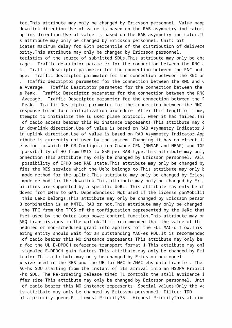
RAB asymmetry indicator.This attribute may only be changed by Ericsson personnel. Value mapping:0: Symmetric Bidirectional1: Asymmetric Unidirectional DL2: Asymmetric Unidirectional UL3: Asymmetric BidirectionalMaximum bit rate in downlink direction.Use of value is based on the RAB asymmetry indicator.This attribute may only be changed by Ericsson personnel. Unit: bpsMaximum bit rate in uplink direction.Use of value is based on the RAB asymmetry indicator.This attribute may only be changed by Ericsson personnel. Unit: bpsMaximum SDU size.This attribute may only be changed by Ericsson personnel. Unit: bitTransfer delay. Indicates maximum delay for 95th percentile of the distribution of delivered SDUs during the lifetime of a bearer service, where delay for an SDU is defined as the time from a request to transfer of an SDU at one SAP to its delivery to the other SAP.Used to specify the delay tolerated by the application. It allows UTRAN to set transport formats and ARQ parameters.This attribute may only be changed by Ericsson personnel. Unit: msTraffic handling priority.This attribute may only be changed by Ericsson personnel. Specifies the characteristics of the source of submitted SDUs.This attribute may only be changed by Ericsson personnel. Value mapping:0: Speech1: UnknownIngress bit rate average. Traffic descriptor parameter for the connection between the RNC and CN.This attribute may only be changed by Ericsson personnel. Value mapping:0: 0 bps1: 64 bps...32000: 2048000 bps (2048 kbps)Unit: 64 bpsIngress bit rate peak. Traffic descriptor parameter for the connection between the RNC and CN.This attribute may only be changed by Ericsson personnel. Value mapping:0: 0 bps1: 64 bps...32000: 2048000 bps (2048 kbps)Unit: 64 bpsEgress bit rate average. Traffic descriptor parameter for the connection between the RNC and CN.This attribute may only be changed by Ericsson personnel. Value mapping:0: 0 bps1: 64 bps...32000: 2048000 bps (2048 kbps)Unit: 64 bpsEgress bit rate peak. Traffic descriptor parameter for the connection between the RNC and CN.This attribute may only be changed by Ericsson personnel. Value mapping:0: 0 bps1: 64 bps...32000: 2048000 bps (2048 kbps)Unit: 64 bpsIngress SsCs SDU Size Average. Traffic Descriptor parameter for the connection between the RNC and CN.This attribute may only be changed by Ericsson personnel. Unit: octetIngress SsCs SDU Size Peak. Traffic Descriptor parameter for the connection between the RNC and CN.This attribute may only be changed by Ericsson personnel. Unit: octetEgress SsCs SDU Size Average. Traffic Descriptor parameter for the connection between the RNC and CN.This attribute may only be changed by Ericsson personnel. Unit: octetEgress SsCs SDU Size Peak. Traffic Descriptor parameter for the connection between the RNC and CN.This attribute may only be changed by Ericsson personnel. Unit: octetTime to wait for CN response to an Iu-c initialization procedure. After this length of time, if no response has been received, RNC repeats the initialization procedure. The maximum number of repeated attempts is defined in noIucInitRep.This attribute may only be changed by Ericsson personnel. Special values:0 is used to indicate that iucInitTimer is not in use.Unit: sChange takes effect: New connectionsNumber of repeated attempts to initialize the Iu user plane protocol, when it has failed.This attribute may only be changed by Ericsson personnel. Special values:0 is used to indicate that noIucInitRep is not in use.Change takes effect: New connectionsIdentifies what kind of radio access bearer this MO instance represents.This attribute may only be changed by Ericsson personnel. Guaranteed bit rate in downlink direction.Use of value is based on RAB Asymmetry Indicator.Applicable for conversational and streaming (value not valid for interactive).Unit: 1 bpsThis attribute may only be changed by Ericsson personnel. Filter: TDDGuaranteed bit rate in uplink direction.Use of value is based on RAB Asymmetry Indicator.Applicable for conversational and streaming (value not valid for interactive).Unit: 1 bpsThis attribute may only be changed by Ericsson personnel. Filter: TDDDeprecated: This attribute is currently not used by the system. Changing it has no effect.Used to determine the value to which IE Activation Time (RRC) and IE CFN (RNSAP and NBAP) shall be set when starting compressed mode.This attribute may only be changed by Ericsson personnel. Value mapping:1: 752: 1203: 150Change takes effect: Next configuration of the transmission gap pattern sequence in UE, DRNC or RBS.Used to determine the value to which IE CM Configuration Change CFN (RNSAP and NBAP) and TGPS reconfiguration CFN (RRC) shall be set when stopping compressed mode.This attribute may only be changed by Ericsson personnel. Value mapping:1: 1002: 1503: 200Change takes effect: Next stop of CPMEnables/disables the possibility of HO from UMTS to GSM per RAB type.This attribute may only be changed by Ericsson personnel. Value mapping:0 : not allowed 1 : allowedChange takes effect: Ongoing connections (next change of RC state)State of the radio connection.This attribute may only be changed by Ericsson personnel. Value mapping:See UeRc class description for list of possible values and their interpretation.Dependencies: This attribute has the same value as the value part of the RDN (UeRcId).Enables/disables the possibility of IFHO per RAB state.This attribute may only be changed by Ericsson personnel. Change takes effect: Ongoing connections (next change of RC state)Filter: FDDThis parameter specifies the RES service which the UeRc belongs to.This attribute may only be changed by Ericsson personnel.Filter: FDDPreferred compressed mode method for the uplink.This attribute may only be changed by Ericsson personnel. Change takes effect: Next state transitionFilter: FDDPreferred compressed mode method for the downlink.This attribute may only be changed by Ericsson personnel. Change takes effect: Next state transitionFilter: FDDIndicates which capabilities are supported by a specific UeRc. This attribute may only be changed by Ericsson personnel. Change takes effect: Next reconfiguration Filter: FDDEnables/disables handover from UMTS to GAN. Dependencies: Not used if the license ganMobility is not active. Change takes effect: Ongoing connections (next change of RC state) This attribute may only be changed by Ericsson personnel.Filter: FDDRES service to which this UeRc belongs.This attribute may only be changed by Ericsson personnel.Filter: TDDIndicates if this RAB combination is an MMTEL RAB or not.This attribute may only be changed by Ericsson personnel.Filter: FDDThe reference TFC is the TFC from the TFCS of the configuration represented by the UeRc that has the most Transport Format information in the TFCS (the TFC that will result in the maximum number of TB's with largest size being applied).This attribute may only be changed by Ericsson personnel. Filter: TDDE-DCH MAC-d power offset used by the Outer loop power control function.This attribute may only be changed by Ericsson personnel. Unit: dBTargeted number of HARQ transmissions in the uplink.It is recommended that the value of this attribute should be the same for all flows under a specific UeRc instance.This attribute may only be changed by Ericsson personnel. Indicates whether scheduled or non-scheduled grant info applies for the EUL MAC-d flow.This attribute may only be changed by Ericsson personnel. Time that the re-ordering entity should wait for an outstanding MAC-es PDU.It is recommended that the value of this attribute should be the same for all flows under a specific UeRc instance.This attribute may only be changed by Ericsson personnel. Unit: msChange takes effect: New connectionsIdentifies what kind of radio bearer this MO instance represents.This attribute may only be changed by Ericsson personnel. Special values:Only the values RB_RRC, RB_PS_INTERACTIVE and RB_PS_INTERACTIVE_2 are applicable for this attribute and MO (even though the other values are allowed to be set).Reference gain factor for the UL E-DPDCH reference transport format 1.This attribute may only be changed by Ericsson personnel. Reference E-TFCI for signaled E-DPDCH gain factors.This attribute may only be changed by Ericsson personnel. Specification: 3GPP 25.321Transport format indicator.This attribute may only be changed by Ericsson personnel. MAC-hs/MAC-ehs window size used in the RBS and the UE for MAC-hs/MAC-ehs data transfer. The parameter value setting is signaled via NBAP and RRC. If MIMO or Multi-Carrier is used for a HS-DSCH connection, the value signaled is min(32, 2 * macHsWindowSize).This attribute may only be changed by Ericsson personnel.Time to live for a MAC-hs SDU starting from the instant of its arrival into an HSDPA Priority Queue. The RBS shall use this information to discard out-of-data MAC-hs SDUs from the HSDPA Priority Queues. The parameter value setting is signaled via NBAP.This attribute may only be changed by Ericsson personnel.Unit: msTime to live for MAC-hs SDU. The Re-ordering release timer T1 controls the stall avoidance in the UE reordering buffer. The parameter value setting is signaled via NBAP and RRC.This attribute may only be changed by Ericsson personnel.Unit: msMAC-hs reordering buffer size.This attribute may only be changed by Ericsson personnel. Unit: kB (1000 bytes)Identifies what kind of radio bearer this MO instance represents. Special values:Only the values RB_RRC, RB_PS_INTERACTIVE_HS, RB_PS_INTERACTIVE_HS_2, RB_PS_INTERACTIVE_HS_3, and RB_PS_STREAMING_HS are applicable for this attribute and MO (even though the other values are allowed to be set).This attribute may only be changed by Ericsson personnel. Filter: FDDPriority Queue ID.This attribute may only be changed by Ericsson personnel. Filter: TDDScheduling priority of a priority queue.0 - Lowest Priority?5 - Highest PriorityThis attribute may only be changed by Ericsson personnel. Filter: TDD
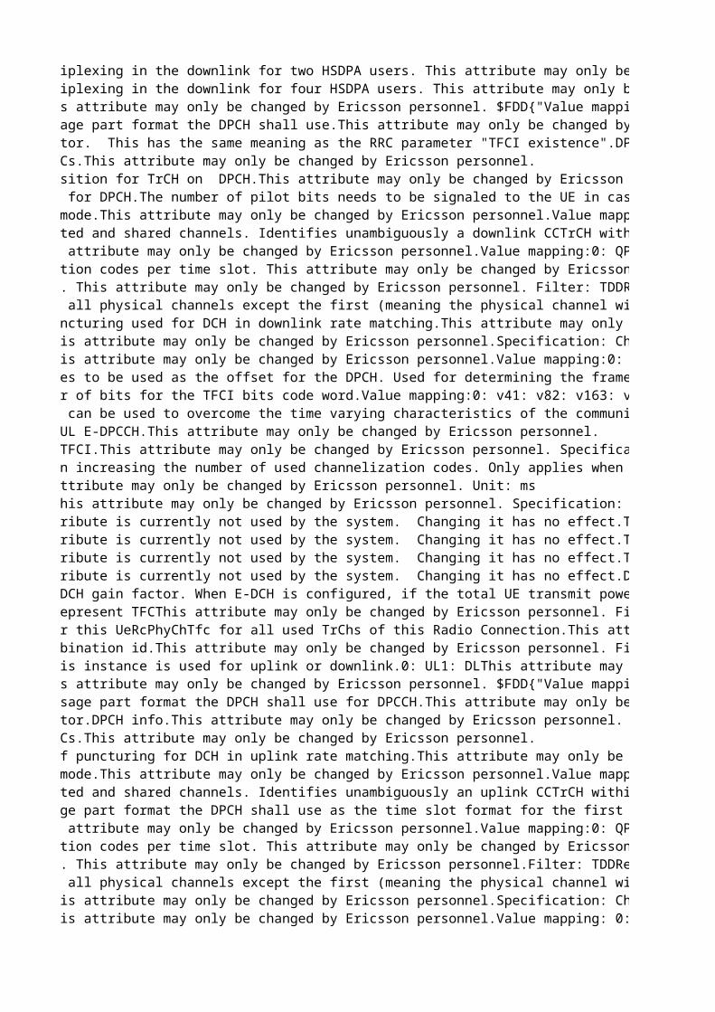
Configures DPCH multiplexing in the downlink for two HSDPA users. This attribute may only be changed by Ericsson personnel.Filter: TDDConfigures DPCH multiplexing in the downlink for four HSDPA users. This attribute may only be changed by Ericsson personnel.Filter: TDDSpreading factor.This attribute may only be changed by Ericsson personnel. $FDD{"Value mapping:0: SF 41: SF 82: SF 163: SF 324: SF 645: SF 1286: SF 2567: SF 512"}$TDD{"Value mapping:0: SF 11: SF 16"}Indicates which message part format the DPCH shall use.This attribute may only be changed by Ericsson personnel. TFCI presence indicator. This has the same meaning as the RRC parameter "TFCI existence".DPCH info.This attribute may only be changed by Ericsson personnel. Value mapping:0: No = TFCI not present; same as "TFCI existence" = FALSE1: Yes = TFCI present; same as "TFCI existence" = TRUECurrent number of TFCs.This attribute may only be changed by Ericsson personnel. Fixed or flexible position for TrCH on DPCH.This attribute may only be changed by Ericsson personnel. Value mapping:0: FIXED1: FLEXIBLEFilter: FDDNumber of pilot bits for DPCH.The number of pilot bits needs to be signaled to the UE in case the downlink physical connection uses spreading factor 128 or 256. In all other cases the UE calculates the number of pilot bits based on slot format information. The number of pilot bits is not signaled towards the RBS. For downlink physical connections using other spreading factors, the configured value will not be used by the RNC, but has to be set anyway since the parameter is defined as mandatory in the MOM. Any of the defined values will work.This attribute may only be changed by Ericsson personnel. Filter: FDDSecond interleaving mode.This attribute may only be changed by Ericsson personnel.Value mapping:0: Frame interleaving1: Time Slot interleaving Filter: TDDCCTrCH ID for dedicated and shared channels. Identifies unambiguously a downlink CCTrCH within a radio link.This attribute may only be changed by Ericsson personnel.Filter: TDDReplaces: tdCcTrChIdModulation mode.This attribute may only be changed by Ericsson personnel.Value mapping:0: QPSK1: 8PSKFilter: TDDReplaces: tdModulationNumber of channelisation codes per time slot. This attribute may only be changed by Ericsson personnel. Filter: TDDReplaces: tdNoChCodesPerTimeSlotNumber of time slots. This attribute may only be changed by Ericsson personnel. Filter: TDDReplaces: tdNoTimeSlotsTime slot format for all physical channels except the first (meaning the physical channel with the least number of time slots and least number of channels). This attribute may only be changed by Ericsson personnel. Filter: TDDReplaces: tdOtherTimeSlotFormatMaximum amount of puncturing used for DCH in downlink rate matching.This attribute may only be changed by Ericsson personnel.Value mapping:0: 40%1: 44%2: 48%...15: 100% Filter: TDDReplaces: tdPunctureLimitRepetition length.This attribute may only be changed by Ericsson personnel.Specification: Chapter 8.6.6.16 in TS 25.331 V4.17.0Filter: TDDReplaces: tdRepetitionLengthRepetition period.This attribute may only be changed by Ericsson personnel.Value mapping:0: RepetitionPeriod_v11: RepetitionPeriod_v22: RepetitionPeriod_v43: RepetitionPeriod_v84: RepetitionPeriod_v165: RepetitionPeriod_v326: RepetitionPeriod_v64Specification: Chapter 8.6.6.16 in TS 25.331 V4.17.0 Filter: TDDReplaces: tdRepetitionPeriodNumber of radio frames to be used as the offset for the DPCH. Used for determining the frame offset from the SFN timing in a cell.This attribute may only be changed by Ericsson personnel.Disturbances:Changing this attribute will affect ongoing traffic.Filter: TDDReplaces: tdTddDpchOffsetValueDetermines the number of bits for the TFCI bits code word.Value mapping:0: v41: v82: v163: v32In case of 8 PSK in 1.28Mcps:v4 corresponds to 6 TFCI code word bits.v8 corresponds to 12 TFCI code word bits.v16 corresponds to 24 TFCI code word bits.v32 corresponds to 48 TFCI code word bits.This attribute may only be changed by Ericsson personnel.Filter: TDDReplaces: tdTfciCodingTSTD indicator. TSTD can be used to overcome the time varying characteristics of the communication channel, Similar to the IE "Tx diversity indicator" for FDD, "TSTD indicator" can be defined and used to inform the application of TSTD to DPCH.This attribute may only be changed by Ericsson personnel.Value mapping:0: active1: inactive Filter: TDDReplaces: tdTstdIndicatorGain factor for the UL E-DPCCH.This attribute may only be changed by Ericsson personnel. E-DCH minimum set E-TFCI.This attribute may only be changed by Ericsson personnel. Specification: 3GPP 25.321Puncturing limit when increasing the number of used channelization codes. Only applies when the number of code channels is less than the maximum allowed by the UE capability and restrictions imposed by UTRAN.This attribute may only be changed by Ericsson personnel. Resolution: 4TTI for E-DCH.This attribute may only be changed by Ericsson personnel. Unit: msE-TFCI table index.This attribute may only be changed by Ericsson personnel. Specification: 3GPP 25.321Deprecated: This attribute is currently not used by the system. Changing it has no effect.TTI budget for an SRB mapped on E-DCH.This attribute may only be changed by Ericsson personnel. Unit: %Deprecated: This attribute is currently not used by the system. Changing it has no effect.TTI budget for a SIP RAB mapped on non-scheduled E-DCH.This attribute may only be changed by Ericsson personnel. Unit: %Deprecated: This attribute is currently not used by the system. Changing it has no effect.TTI budget for scheduled flows on E-DCH.This attribute may only be changed by Ericsson personnel. Unit: %Deprecated: This attribute is currently not used by the system. Changing it has no effect.Defines the E-DCH multiplexing option for this E-DCH radio configuration.Value mapping:0: No multiplexing except among scheduled flows.1: Multiplexing among non-scheduled flows allowed except between SRB and a non-scheduled SIP (if exists), among scheduled flows allowed, but not between scheduled and non-scheduled flows.2: All multiplexing allowed except between SRB and scheduled flows or non-scheduled SIP (if exists).3: All multiplexing allowed except between SRB and a non-scheduled SIP (if exists). This attribute may only be changed by Ericsson personnel. Minimum reduced E-DPDCH gain factor. When E-DCH is configured, if the total UE transmit power (after applying DPCCH power adjustments and gain factors) would exceed the available maximum power, the UE shall firstly reduce the E-DPDCH power with the E-DPDCH gain factor so that the total transmit power would be equal to the available maximum power. If the total transmit power is still higher than the available maximum power after applying the gain factor the E-DPDCH and the DPCCH are equally scaled to meet the available maximum power. This parameter configures the minimum factor to be used by Rel-8 UEs for reduction of the E-DPDCH gain factor. The configured value is divided by 15 to obtain the scaling factor used by the UE. -1 means that this attribute is not applicable for this instance.This attribute may only be changed by Ericsson personnel.Unit: 1 / 15 Change takes effect: ImmediatelyAlternative way to represent TFCThis attribute may only be changed by Ericsson personnel. Filter: TDDArray of TFI data for this UeRcPhyChTfc for all used TrChs of this Radio Connection.This attribute may only be changed by Ericsson personnel. Filter: TDDTransport format combination id.This attribute may only be changed by Ericsson personnel. Filter: TDDIndicates whether this instance is used for uplink or downlink.0: UL1: DLThis attribute may only be changed by Ericsson personnel. Filter: TDDSpreading factor.This attribute may only be changed by Ericsson personnel. $FDD{"Value mapping:0: SF 41: SF 82: SF 163: SF 324: SF 645: SF 1286: SF 2567: SF 512"}$TDD{"Value mapping:0: SF 11: SF 22: SF 43: SF 84: SF 16 "}Indicates which message part format the DPCH shall use for DPCCH.This attribute may only be changed by Ericsson personnel. Filter: FDDTFCI presence indicator.DPCH info.This attribute may only be changed by Ericsson personnel. Value mapping:0: No = TFCI not present1: Yes = TFCI presentCurrent number of TFCs.This attribute may only be changed by Ericsson personnel. The maximum amount of puncturing for DCH in uplink rate matching.This attribute may only be changed by Ericsson personnel. Value mapping:0: 40 %1: 44 %2: 48 %...15: 100 %Unit: %Second interleaving mode.This attribute may only be changed by Ericsson personnel.Value mapping: 0: Frame interleaving1: Time Slot interleaving Filter: TDDReplaces: td2ndInterleavingModeCCTrCH ID for dedicated and shared channels. Identifies unambiguously an uplink CCTrCH within a radio link.This attribute may only be changed by Ericsson personnel. Filter: TDDReplaces: tdCcTrChIdControls which message part format the DPCH shall use as the time slot format for the first physical channel (meaning the physical channel with the least number of time slots and least number of channels). This attribute may only be changed by Ericsson personnel. Filter: TDDReplaces: tdDpchSlotFormatModulation mode.This attribute may only be changed by Ericsson personnel.Value mapping:0: QPSK1: 8PSK Filter: TDDReplaces: tdModulationNumber of channelisation codes per time slot. This attribute may only be changed by Ericsson personnel.Filter: TDDReplaces: tdNoChCodesPerTimeSlotNumber of time slots. This attribute may only be changed by Ericsson personnel.Filter: TDDReplaces: tdNoTimeSlotsTime slot format for all physical channels except the first (meaning the physical channel with the least number of time slots and least number of channels). This attribute may only be changed by Ericsson personnel.Filter: TDDReplaces: tdOtherTimeSlotFormatRepetition length.This attribute may only be changed by Ericsson personnel.Specification: Chapter 8.6.6.16 in TS 25.331 V4.17.0Filter: TDDReplaces: tdRepetitionLengthRepetition period.This attribute may only be changed by Ericsson personnel.Value mapping: 0: RepetitionPeriod_v11: RepetitionPeriod_v22: RepetitionPeriod_v43: RepetitionPeriod_v84: RepetitionPeriod_v165: RepetitionPeriod_v326: RepetitionPeriod_v64Specification: Chapter 8.6.6.16 in TS 25.331 V4.17.0 Filter: TDDReplaces: tdRepetitionPeriod
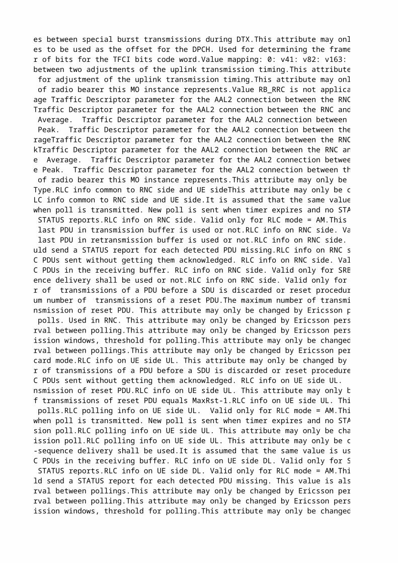
Number of radio frames between special burst transmissions during DTX.This attribute may only be changed by Ericsson personnel. Filter: TDDReplaces: tdSpecialBurstSchedulingNumber of radio frames to be used as the offset for the DPCH. Used for determining the frame offset from the SFN timing in a cell.This attribute may only be changed by Ericsson personnel.Disturbances:Changing this attribute will affect ongoing traffic.Filter: TDDReplaces: tdTddDpchOffsetValueDetermines the number of bits for the TFCI bits code word.Value mapping: 0: v41: v82: v163: v32In case of 8 PSK in 1.28Mcps:v4 corresponds to 6 TFCI code word bits.v8 corresponds to 12 TFCI code word bits.v16 corresponds to 24 TFCI code word bits.v32 corresponds to 48 TFCI code word bits.This attribute may only be changed by Ericsson personnel.Filter: TDDReplaces: tdTfciCodingNumber of subframes between two adjustments of the uplink transmission timing.This attribute may only be changed by Ericsson personnel.Filter: TDDReplaces: tdUlSynchronizationStepFrequencyStep size to be used for adjustment of the uplink transmission timing.This attribute may only be changed by Ericsson personnel.Unit: 1/8 chipFilter: TDDReplaces: tdUlSynchronizationStepSizeIdentifies what kind of radio bearer this MO instance represents.Value RB_RRC is not applicable for this attribute and MO (but is nonetheless allowed to be set).This attribute may only be changed by Ericsson personnel. Egress Bit Rate Average Traffic Descriptor parameter for the AAL2 connection between the RNC and RBS for the RAB leg.0: 0 bit/s1: 64 bit/s..32000: 2048000 bit/s (2048 kbit/s)This attribute may only be changed by Ericsson personnel. Filter: TDDEgress Bit Rate PeakTraffic Descriptor parameter for the AAL2 connection between the RNC and RBS for the RAB leg.0: 0 bit/s1: 64 bit/s..32000: 2048000 bit/s (2048 kbit/s)This attribute may only be changed by Ericsson personnel. Filter: TDDEgress SsCs SDU Size Average. Traffic Descriptor parameter for the AAL2 connection between the RNC and RBS for the RAB leg.Unit: 1 octetThis attribute may only be changed by Ericsson personnel. Filter: TDDEgress SsCs SDU Size Peak. Traffic Descriptor parameter for the AAL2 connection between the RNC and RBS for the RAB leg.Unit: 1 octetThis attribute may only be changed by Ericsson personnel. Filter: TDDIngress Bit Rate AverageTraffic Descriptor parameter for the AAL2 connection between the RNC and RBS for the RAB leg.0: 0 bit/s1: 64 bit/s..32000: 2048000 bit/s (2048 kbit/s)This attribute may only be changed by Ericsson personnel. Filter: TDDIngress Bit Rate PeakTraffic Descriptor parameter for the AAL2 connection between the RNC and RBS for the RAB leg.0: 0 bit/s1: 64 bit/s..32000: 2048000 bit/s (2048 kbit/s)This attribute may only be changed by Ericsson personnel. Filter: TDDIngress SsCs SDU Size Average. Traffic Descriptor parameter for the AAL2 connection between the RNC and RBS for the RAB leg.Unit: 1 octetThis attribute may only be changed by Ericsson personnel. Filter: TDDIngress SsCs SDU Size Peak. Traffic Descriptor parameter for the AAL2 connection between the RNC and RBS for the RAB leg.Unit: 1 octetThis attribute may only be changed by Ericsson personnel. Filter: TDDIdentifies what kind of radio bearer this MO instance represents.This attribute may only be changed by Ericsson personnel. Special values:Value RB_PACKET_ADCH, RB_PACKET_ADCH_2, RB_PACKET_ADCH_3 and RB_STREAMING_ADCH are not applicable for this attribute and MO (but are nonetheless allowed to be set).RLC Logical Channel Type.RLC info common to RNC side and UE sideThis attribute may only be changed by Ericsson personnel. Value mapping:0: DCCH Dedicated Control Ch. Valid only on DCS side1: DTCH Dedicated Traffic Ch. Valid only on DCS side2: BCCH Broadcast Control Channel. Valid only on CCS side.3: CCCH Common Control Channel. Valid only on CCS side.4: PCCH Paging Control Channel. Valid only on CCS side.RLC transport mode.RLC info common to RNC side and UE side.It is assumed that the same value is used for both DL and UL.0: Acknowledged (AM)1: Transparent (TM)2: Unacknowledged (UM)This attribute may only be changed by Ericsson personnel. Timer poll, started when poll is transmitted. New poll is sent when timer expires and no STATUS is received.RLC info on RNC side. Valid only for RLC mode = AM.This attribute may only be changed by Ericsson personnel. Special values:0: not used Unit: msMinimum time between STATUS reports.RLC info on RNC side. Valid only for RLC mode = AM.This attribute may only be changed by Ericsson personnel. Special values:0: not used Unit: msIndicates if poll at last PDU in transmission buffer is used or not.RLC info on RNC side. Valid only for RLC mode = AM.This attribute may only be changed by Ericsson personnel. Value mapping:0: poll not used1: poll usedIndicates if poll at last PDU in retransmission buffer is used or not.RLC info on RNC side. Valid only for RLC mode = AM.This attribute may only be changed by Ericsson personnel. Value mapping:0: poll not used1: poll usedIndicates if RNC should send a STATUS report for each detected PDU missing.RLC info on RNC side. Valid only for RLC mode = AM.This attribute may only be changed by Ericsson personnel. Value mapping:0: RNC shall not send STATUS reports1: RNC shall send STATUS reportsMaximum number of RLC PDUs sent without getting them acknowledged. RLC info on RNC side. Valid only for SRB with RLC mode = AM.This attribute may only be changed by Ericsson personnel.Maximum number of RLC PDUs in the receiving buffer. RLC info on RNC side. Valid only for SRB with RLC mode = AM.This attribute may only be changed by Ericsson personnel.Indicates if in-sequence delivery shall be used or not.RLC info on RNC side. Valid only for RLC mode = UM and AM.This attribute may only be changed by Ericsson personnel. Value mapping:0: the value can be configured but in-sequence delivery will still be used, that is, in-sequence delivery is predefined.1: in-sequence delivery shall be usedDetermines the number of transmissions of a PDU before a SDU is discarded or reset procedure is initiated.The maximum number of transmissions of a PDU equals MaxDat-1.RLC info on RNC side. Valid only for RLC mode = AM.This attribute may only be changed by Ericsson personnel. Determines the maximum number of transmissions of a reset PDU.The maximum number of transmissions of a reset PDU equals MaxRst-1.RLC info on RNC side. Valid only for RLC mode = AM.This attribute may only be changed by Ericsson personnel. Timer used for retransmission of reset PDU. This attribute may only be changed by Ericsson personnel. Special values:0: not used Unit: msMinimum time between polls. Used in RNC. This attribute may only be changed by Ericsson personnel. Special values:0: not used Unit: msNumber of SDUs, interval between polling.This attribute may only be changed by Ericsson personnel. Special values:0: attribute not usedPercentage of transmission windows, threshold for polling.This attribute may only be changed by Ericsson personnel. Special values:0: not usedUnit: %Number of PDUs, interval between pollings.This attribute may only be changed by Ericsson personnel. Special values:0: not usedTransmission SDU discard mode.RLC info on UE side UL. This attribute may only be changed by Ericsson personnel. Value mapping:0: Timer Based Explicit (can be configured but is not used)1: Timer Based No Explicit (can be configured but is not used)2: Max Dat (can be configured but is not used)3: No Discard (AM), SDU Discard not configured (TM and UM)Determines the number of transmissions of a PDU before a SDU is discarded or reset procedure is initiated.The number of transmissions is equal to MaxDat - 1.RLC info on UE side UL. Valid only for RLC mode = AM.This attribute may only be changed by Ericsson personnel. Value mapping: 2: MaxDat = 3 3: 4 4: 5 5: 6 6: 7 7: 8 8: 9 9: 1010: 1511: 2012: 2513: 3014: 3515: MaxDat = 40 Maximum number of RLC PDUs sent without getting them acknowledged. RLC info on UE side UL. Valid only for SRB with RLC mode = AM. This attribute may only be changed by Ericsson personnel. Value mapping: 0:1 Max PDU sent 1:8 2:16 3:32 4:64 5:128 6:256 7:512 8:768 9:1024 10:1536 11:2047 12:2560 13:3072 14:3584Timer used for retransmission of reset PDU.RLC info on UE side UL. This attribute may only be changed by Ericsson personnel. Value mapping: 0: 50 ms 1: 100 ms 2: 150 ms ..11: 600 ms12: 700 ms..15: 1000 msUnit: msThe maximum number of transmissions of reset PDU equals MaxRst-1.RLC info on UE side UL. This attribute may only be changed by Ericsson personnel. Value mapping:0: MaxRst = 11: 42: 63: 84: 125: 166: 247: MaxRst =32Minimum time between polls.RLC polling info on UE side UL. Valid only for RLC mode = AM.This attribute may only be changed by Ericsson personnel. Special values: -1: not used 10..550 ms with resolution 10600..1000ms with resolution 50Unit: msTimer poll, started when poll is transmitted. New poll is sent when timer expires and no STATUS is received.RLC polling info on UE side UL. Valid only for RLC mode = AM.This attribute may only be changed by Ericsson personnel. Special values:-1: not used 10 .. 550 ms with resolution 10600 ..1000ms with resolution 50Unit: msLast PDU in transmission poll.RLC polling info on UE side UL. This attribute may only be changed by Ericsson personnel. Value mapping:0: not last PDU in Transmission Poll1: last PDU in Transmission PollLast PDU in retransmission poll.RLC polling info on UE side UL. This attribute may only be changed by Ericsson personnel. Value mapping:0: not last PDU in Retransmission Poll1: last PDU in Retransmission PollIndicates whether in-sequence delivery shall be used.It is assumed that the same value is used for both DL and UL.RLC info on UE side DL. Valid for RLC mode = AM and UM.This attribute may only be changed by Ericsson personnel. Value mapping:0: in-sequence delivery shall not be used1: in-sequence delivery shall be usedMaximum number of RLC PDUs in the receiving buffer. RLC info on UE side DL. Valid only for SRB with RLC mode = AM. This attribute may only be changed by Ericsson personnel. Value mapping: 0:1 PDU in buffer 1:8 2:16 3:32 4:64 5:128 6:256 7:512 8:768 9:1024 10:1536 11:2047 12:2560 13:3072 14:3584 15:4095Minimum time between STATUS reports.RLC info on UE side DL. Valid only for RLC mode = AM.This attribute may only be changed by Ericsson personnel. Special values: -1: not used 10..550 ms with resolution 10600..1000ms with resolution 50Unit: msIndicates if UE should send a STATUS report for each detected PDU missing. This value is also used in DL RLC Status Info sent on RRC.RLC info on UE side DL. Valid only for RLC mode = AM.This attribute may only be changed by Ericsson personnel. Value mapping:0: UE shall not send STATUS reports1: UE shall send STATUS reportsNumber of SDUs, interval between pollings.This attribute may only be changed by Ericsson personnel. Value mapping:-1 Attribute not used.0 1 SDU interval 1 4 SDU intervals 2 16 SDU intervals 3 64 SDU intervalsNumber of SDUs, interval between polling.This attribute may only be changed by Ericsson personnel. Value mapping:-1 Attribute not used.0 1 PDU interval 1 2 PDU interval 2 4 PDU interval 3 8 PDU interval 4 16 PDU interval 5 32 PDU interval 6 64 PDU interval 7 128 PDU intervalPercentage of transmission windows, threshold for polling.This attribute may only be changed by Ericsson personnel. Special values:0: not usedUnit: %
Transport Channel Identity (DCH Id) which gives the association between RB and Transport Channel.RB Mapping Info. This attribute may only be changed by Ericsson personnel. Logical Channel Multiplexing indicator in MacD.RB Mapping Info. This attribute may only be changed by Ericsson personnel. Value mapping:0: multiplexing is not performed1: multiplexing is performedTransport Channel Type DL.RB Mapping Info.This attribute may only be changed by Ericsson personnel. Value mapping:0: DCH1: FACH2: DSCH3: HS-DSCHTransport Channel Type UL.RB Mapping Info. Valid for RLC mode = UM, AM and TM.This attribute may only be changed by Ericsson personnel. Value mapping:-1: Not Applicable0: DCH1: RACH2: CPCH3: E-DCHIdentifies the user of this radio bearer.This attribute may only be changed by Ericsson personnel. Filter: FDDLogical Channel Identity.Used when several RBs are muxed to single DCH (1 is used for first RB of RRC).RB Mapping Info.This attribute may only be changed by Ericsson personnel. Filter: TDDLogical Channel PriorityUsed when several RBs are muxed to single DCH (1 is used for highest priority i.e. for the first RB of RRC).RB Mapping Info.This attribute may only be changed by Ericsson personnel. Filter: TDDRadio Bearer Identity.1: SRB12: SRB23: SRB34: SRB45-32:used by other types of radio bearersThis attribute may only be changed by Ericsson personnel. Filter: TDDRLC User Type, used to inform the RLC about which interface to use.RLC info is common to both the RNC side and the UE side.0=Rrc1=Speech2=Udi3=PsInteractive4=CsStreaming5=PsStreamingThis attribute may only be changed by Ericsson personnel. Filter: TDDMaximum Flexible RLC PDU size.This attribute may only be changed by Ericsson personnel.Dependencies: The value used for this RAB is the minimum of maxMacdPduSizeExtended and IurLink::maxMacdPduSizeExtendedUnit: bytesChange takes effect: New connectionsDetermines the number of transmissions of a PDU before a SDU is discarded or reset procedure is initiated.The maximum number of transmissions of a PDU equals MaxDat-1.This attribute may only be changed by Ericsson personnel. Determines the maximum number of transmissions of a reset PDU.The maximum number of transmissions of a reset PDU equals MaxRst-1.This attribute may only be changed by Ericsson personnel. Percentage of transmission windows, threshold for polling.This attribute may only be changed by Ericsson personnel. Unit: %Maximum number of RLC PDUs in the receiving buffer. RLC info on RNC side. Valid only for RLC mode = AM.This attribute may only be changed by Ericsson personnel.Timer poll, started when poll is transmitted. New poll is sent when timer expires and no STATUS is received.RLC info on RNC side. Valid only for RLC mode = AM.This attribute may only be changed by Ericsson personnel. Unit: msTimer used for retransmission of reset PDU. This attribute may only be changed by Ericsson personnel. Unit: msMinimum time between STATUS reports.RLC info on RNC side. Valid only for RLC mode = AM.This attribute may only be changed by Ericsson personnel. Unit: msMaximum number of RLC PDUs sent without getting them acknowledged. RLC info on RNC side. Valid only for RLC mode = AM. This attribute may only be changed by Ericsson personnel.Determines the number of transmissions of a PDU before a SDU is discarded or reset procedure is initiated.The number of transmissions is equal to MaxDat - 1.This attribute may only be changed by Ericsson personnel. Value mapping: 2: MaxDat = 3 3: 4 4: 5 5: 6 6: 7 7: 8 8: 9 9: 1010: 1511: 2012: 2513: 3014: 3515: MaxDat = 40 The maximum number of transmissions of reset PDU equals MaxRst-1.This attribute may only be changed by Ericsson personnel. Value mapping:0: MaxRst = 11: 42: 63: 84: 125: 166: 247: MaxRst =32Percentage of transmission windows, threshold for polling.This attribute may only be changed by Ericsson personnel. Unit: %Maximum number of RLC PDUs in the receiving buffer. RLC info on UE side DL. Valid only for SRB with RLC mode = AM. This attribute may only be changed by Ericsson personnel. Value mapping: 0:1 PDU in buffer 1:8 2:16 3:32 4:64 5:128 6:256 7:512 8:768 9:1024 10:1536 11:2047 12:2560 13:3072 14:3584 15:4095Timer poll, started when poll is transmitted. New poll is sent when timer expires and no STATUS is received.RLC polling info on UE side UL. Valid only for RLC mode = AM.This attribute may only be changed by Ericsson personnel. Value mapping:10 .. 550 ms with resolution 10600 ..1000ms with resolution 50Unit: msTimer used for retransmission of reset PDU.RLC info on UE side UL. This attribute may only be changed by Ericsson personnel. Value mapping: 0: 50 ms 1: 100 ms 2: 150 ms ..11: 600 ms12: 700 ms..15: 1000 msUnit: msMinimum time between STATUS reports.RLC info on UE side DL. Valid only for RLC mode = AM.This attribute may only be changed by Ericsson personnel. Value mapping:10..550 ms with resolution 10600..1000ms with resolution 50Unit: msMaximum number of RLC PDUs sent without getting them acknowledged. RLC info on UE side UL. Valid only for RLC mode = AM.This attribute may only be changed by Ericsson personnel. Value mapping: 0:1 Max PDU sent 1:8 2:16 3:32 4:64 5:128 6:256 7:512 8:768 9:1024 10:1536 11:2047 12:2560 13:3072 14:3584Ingress Bit Rate Average Traffic Descriptor parameter for the AAL2 connection between the RNC and RBS for the RRC leg.0: 0 bit/s1: 64 bit/s..32000: 2048000 bit/s (2048 kbit/s)This attribute may only be changed by Ericsson personnel. Filter: TDDIngress Bit Rate PeakTraffic Descriptor parameter for the AAL2 connection between the RNC and RBS for the RRC leg.0: 0 bit/s1: 64 bit/s..32000: 2048000 bit/s (2048 kbit/s)This attribute may only be changed by Ericsson personnel. Filter: TDDEgress Bit Rate AverageTraffic Descriptor parameter for the AAL2 connection between the RNC and RBS for the RRC leg.0: 0 bit/s1: 64 bit/s..32000: 2048000 bit/s (2048 kbit/s)This attribute may only be changed by Ericsson personnel. Filter: TDDEgress Bit Rate PeakTraffic Descriptor parameter for the AAL2 connection between the RNC and RBS for the RRC leg.0: 0 bit/s1: 64 bit/s..32000: 2048000 bit/s (2048 kbit/s)This attribute may only be changed by Ericsson personnel. Filter: TDDIngress SsCs SDU Size Average in octets.Traffic Descriptor parameter for the AAL2 connection between the RNC and RBS for the RRC leg.This attribute may only be changed by Ericsson personnel. Filter: TDDIngress SsCs SDU Size Peak in octets.Traffic Descriptor parameter for the AAL2 connection between the RNC and RBS for the RRC leg.This attribute may only be changed by Ericsson personnel. Filter: TDDEgress SsCs SDU Size Average in octets.Traffic Descriptor parameter for the AAL2 connection between the RNC and RBS for the RRC leg.This attribute may only be changed by Ericsson personnel. Filter: TDDEgress SsCs SDU Size Peak in octets.Traffic Descriptor parameter for the AAL2 connection between the RNC and RBS for the RRC leg.This attribute may only be changed by Ericsson personnel. Filter: TDDTransport channel type.This attribute may only be changed by Ericsson personnel. Filter: TDDTransport Channel Identity.This attribute may only be changed by Ericsson personnel. Identifies what kind of radio bearer this MO instance represents.This attribute may only be changed by Ericsson personnel. Special values:Values RB_PS_INTERACTIVE_HS, RB_PS_INTERACTIVE_2, RB_PS_INTERACTIVE_3, RB_PS_INTERACTIVE_HS_2, RB_PS_INTERACTIVE_HS_3, RB_PACKET_ADCH_2 and RB_PACKET_ADCH_3, RB_PS_STREAMING_HS are not applicable for this attribute and MO (but are nonetheless allowed to be set).DCH Frame Protocol Identity. This is the group that a DCH belongs to. In case of coordinated DCHs, all of them shall have the same attribute value.Frame Handling parameter.This attribute may only be changed by Ericsson personnel. Frame Handling Priority.Frame Handling parameter.This attribute may only be changed by Ericsson personnel. Value mapping: 0: Lowest priority...15: Highest priorityPayload Cyclic Redundancy Check (CRC) usage indicator (to SP and NBAP/RRC).Frame Handling parameter.Note: NBAP/RRC messages use the opposite enumeration as shown below.This attribute may only be changed by Ericsson personnel. Value mapping:0: False1: TrueUL Format Protocol (NBAP).Frame Handling parameter.This attribute may only be changed by Ericsson personnel. Value mapping:-1: Not Applicable0: Normal1: SilentCurrent number of TFs defined in downlink.This attribute may only be changed by Ericsson personnel. Transport block size for this TF in downlink.This attribute may only be changed by Ericsson personnel. Unit: bitsNumber of transport blocks for this TF in downlink.This attribute may only be changed by Ericsson personnel. Transport block size for this TF in downlink.This attribute may only be changed by Ericsson personnel. Unit: bitsNumber of transport blocks for this TF in downlink.This attribute may only be changed by Ericsson personnel. Transport block size for this TF in downlink.This attribute may only be changed by Ericsson personnel. Unit: bitsNumber of transport blocks for this TF in downlink.This attribute may only be changed by Ericsson personnel.
Transport block size for this TF in downlink.This attribute may only be changed by Ericsson personnel. Unit: bitsNumber of transport blocks for this TF in downlink.This attribute may only be changed by Ericsson personnel. Transport block size for this TF in downlink.This attribute may only be changed by Ericsson personnel. Unit: bitsNumber of transport blocks for this TF in downlink.This attribute may only be changed by Ericsson personnel. Transport block size for this TF in downlink.This attribute may only be changed by Ericsson personnel. Unit: bitsNumber of transport blocks for this TF in downlink.This attribute may only be changed by Ericsson personnel. Transmission time interval in downlink.This attribute may only be changed by Ericsson personnel. Value mapping:0: 10 ms1: 20 ms2: 40 ms3: 80 ms Unit: msChannel coding type in downlink.This attribute may only be changed by Ericsson personnel. Value mapping:0: No Coding1: Convolutional2: TurboChannel coding rate in downlink.This attribute may only be changed by Ericsson personnel. Value mapping:0: Coding rate = 1/21: Coding rate = 1/3CRC size in downlink.This attribute may only be changed by Ericsson personnel. Value mapping:0: 0 bits1: 82: 123: 164: 24 bitsUnit: bitsCurrent number of TFs defined in uplink.This attribute may only be changed by Ericsson personnel. Special values:-1: Not ApplicableTransport block size for this TF in uplink.This attribute may only be changed by Ericsson personnel. Unit: bitsNumber of transport blocks for this TF in uplink.This attribute may only be changed by Ericsson personnel. Transport block size for this TF in uplink.This attribute may only be changed by Ericsson personnel. Unit: bitsNumber of transport blocks for this TF in uplink.This attribute may only be changed by Ericsson personnel. Transport block size for this TF in uplink.This attribute may only be changed by Ericsson personnel. Unit: bitsNumber of transport blocks for this TF in uplink.This attribute may only be changed by Ericsson personnel. Transport block size for this TF in uplink.This attribute may only be changed by Ericsson personnel. Unit: bitsNumber of transport blocks for this TF in uplink.This attribute may only be changed by Ericsson personnel. Transport block size for this TF in uplink.This attribute may only be changed by Ericsson personnel. Unit: bitsNumber of transport blocks for this TF in uplink.This attribute may only be changed by Ericsson personnel. Transport block size for this TF in uplink.This attribute may only be changed by Ericsson personnel. Unit: bitsNumber of transport blocks for this TF in uplink.This attribute may only be changed by Ericsson personnel. Transmission Time Interval in uplink.This attribute may only be changed by Ericsson personnel. Value mapping:-1: Not Applicable0: 10 ms1: 20 ms2: 40 ms3: 80 ms Unit: msChannel coding type in uplink.This attribute may only be changed by Ericsson personnel. Value mapping:0: No Coding1: Convolutional2: TurboChannel coding rate in uplink.This attribute may only be changed by Ericsson personnel. Value mapping:-1: Not Applicable0: Coding rate = 1/21: Coding rate = 1/3CRC size in uplink.This attribute may only be changed by Ericsson personnel. Value mapping:-1: Not Applicable0: 0 bits1: 82: 123: 164: 24 bitsUnit: bits$FDD{"Array of the maximum Transport Formats (TFIs) allowed for this TrCH.The first element in the array specifies the maximum TFI for TFC Subset 0, the second element specifies the maximum TFI for TFC Subset 1, and so forth."}$TDD{"Element [0] is used as the equivalent of rateMatchingAttrDlTdd: Rate matching attribute in downlink.Element [1] is used as the equivalent of rateMatchingAttrUlTdd: Rate matching attribute in uplink.The remaining elements are not used."}The attribute must have all elements set.This attribute may only be changed by Ericsson personnel. Special values:-1: not applicableControls whether quality evaluation is used for the downlink transport channel.Value mapping: 0: Quality evaluation not used1: Quality evaluation used2: Quality evaluation IE will not be sent in the NBAP message.This attribute may only be changed by Ericsson personnel. Filter: TDDReplaces: tdDlQeSelectorNumber of transport blocks for this TF in downlink.This attribute may only be changed by Ericsson personnel. Filter: TDDReplaces: tdNoOfTbTf6DlNumber of transport blocks for this TF in uplink.This attribute may only be changed by Ericsson personnel. Filter: TDDReplaces: tdNoOfTbTf6UlNumber of transport blocks for this TF in downlink.This attribute may only be changed by Ericsson personnel. Filter: TDDReplaces: tdNoOfTbTf7DlNumber of transport blocks for this TF in uplink.This attribute may only be changed by Ericsson personnel. Filter: TDDReplaces: tdNoOfTbTf7UlNumber of transport blocks for this TF in downlink.This attribute may only be changed by Ericsson personnel. Filter: TDDReplaces: tdNoOfTbTf8DlNumber of transport blocks for this TF in uplink.This attribute may only be changed by Ericsson personnel. Filter: TDDReplaces: tdNoOfTbTf8UlNumber of transport blocks for this TF in downlink.This attribute may only be changed by Ericsson personnel. Filter: TDDReplaces: tdNoOfTbTf9DlNumber of transport blocks for this TF in uplink.This attribute may only be changed by Ericsson personnel. Filter: TDDReplaces: tdNoOfTbTf9UlTransport block size for this TF in downlink.This attribute may only be changed by Ericsson personnel. Unit: bitsFilter: TDDReplaces: tdSizeOfTbTf6DlTransport block size for this TF in uplink.This attribute may only be changed by Ericsson personnel. Unit: bitsFilter: TDDReplaces: tdSizeOfTbTf6UlTransport block size for this TF in downlink.This attribute may only be changed by Ericsson personnel. Unit: bitsFilter: TDDReplaces: tdSizeOfTbTf7DlTransport block size for this TF in uplink.This attribute may only be changed by Ericsson personnel. Unit: bitsFilter: TDDReplaces: tdSizeOfTbTf7UlTransport block size for this TF in downlink.This attribute may only be changed by Ericsson personnel. Unit: bitsFilter: TDDReplaces: tdSizeOfTbTf8DlTransport block size for this TF in uplink.This attribute may only be changed by Ericsson personnel. Unit: bitsFilter: TDDReplaces: tdSizeOfTbTf8UlTransport block size for this TF in downlink.This attribute may only be changed by Ericsson personnel. Unit: bitsFilter: TDDReplaces: tdSizeOfTbTf9DlTransport block size for this TF in uplink.This attribute may only be changed by Ericsson personnel. Unit: bitsFilter: TDDReplaces: tdSizeOfTbTf9UlUsed by MAC-D in connection with higher layer scheduling when calculating data amounts to be sent downlink. This attribute may only be changed by Ericsson personnel. Filter: TDDDCH Combination Indicator.Frame Handling parameter.This attribute may only be changed by Ericsson personnel. Filter: TDDPower congestion filter.Used by Congestion Control.This attribute may only be changed by Ericsson personnel. Change takes effect: Re-initiation of DL TX carrier power measurements
Defines the periodicity of the DL cell carrier power measurement reporting.Used by CellLoad Monitor Initialization in Admission Control.The configured value is divided by 10 by the RNC traffic application before it is sent on NBAP to RBS.This attribute may only be changed by Ericsson personnel. Disturbances:Changing this attribute may affect ongoing traffic.Unit: msResolution: 100Change takes effect: Re-initiation of Admission Control measurementsDefines the RBS internal filtering.Used by CellLoad Monitor Initialization in Admission Control.This attribute may only be changed by Ericsson personnel. Disturbances:Changing this attribute may affect ongoing traffic.Change takes effect: Re-initiation of Admission Control measurementsAttack factor for filtering the measured/estimated power consumption.Used by Cell Load Monitor in Admission Control.This attribute may only be changed by Ericsson personnel. Disturbances:Changing this attribute may affect ongoing traffic. Whenever its value is set, the cell is disabled automatically and then re-enabled.Change takes effect: Object disabled/enabledUnit: %Decay factor for filtering the measured/estimated power consumption.Used by Cell Load Monitor in Admission Control.This attribute may only be changed by Ericsson personnel. Unit: %Change takes effect: ImmediatelyFactor to take the flexibility of the TFS for a DCH into account when calculating the ASE. This attribute may only be changed by Ericsson personnel. Disturbances:Changing this attribute may affect ongoing traffic. Whenever its value is set, the cell is disabled automatically and then re-enabled.Change takes effect: Object disabled/enabledUnit: 0.01RTWP measurement filter coefficient.This attribute may only be changed by Ericsson personnel. Change takes effect: Re-initiation of UL RTWP measurementsReporting interval for transmitted carrier power measurements between reports A and B.It is recommended to set this attribute to an integral multiple of txInterval (in ms).This attribute may only be changed by Ericsson personnel. Unit: 10 msFilter: TDDRobustness timer for end of congestion detection.Used by Congestion Control.This attribute may only be changed by Ericsson personnel. Unit: msFilter: TDDScaling factor for the estimation of the DL power consumption per RL. Unit: 0.01Changing this attribute may affect ongoing traffic.This attribute may only be changed by Ericsson personnel. Filter: TDD
System default ARP values used when the ARP mapping feature is not activated through its RncFeature MO instance.This attribute may only be changed by Ericsson personnel. Dependencies:The values in this attribute are displayed in the read-only attribute systemDefaultArpQosFilter: FDDBuffering/processing time in the RNC for a FACH/PCH data frame on the downlink. Part of the Downlink Offset (DO). Should be set to the upper limit of the delay within the RNC in the transmission of each frame.The actual buffering/processing time is affected by the type of traffic frame (transport block type) as well as load, processing type, etc. If this value is set too low, frames may be lost or discarded (due to too-late arrival).This attribute may only be changed by Ericsson personnel. Unit: msBuffering/processing time in the RBS for a FACH/PCH data frame on the downlink. Part of the Downlink Offset (DO). Should be set to the upper limit of the delay within the RBS in the transmission of each frame.The actual buffering/processing time is affected by the type of traffic frame (transport block type) as well as load, processing type, etc. If this value is set too low, frames may be lost or discarded (due to "too late" arrival).This attribute may only be changed by Ericsson personnel. Unit: ms
Time after a channel switch is requested, after which the next measurement report may be sent from either the UE or RNC internal buffer load measurements. Used to limit the UE and RNC buffer load reporting intensity.This attribute may only be changed by Ericsson personnel. Value mapping:0: 0.25 s1: 0.5 s2: 1 s3: 2 s4: 4 s5: 8 s6: 16 sChange takes effect: New connectionsAveraging period of the UL and/or DL throughput measurement.This attribute may only be changed by Ericsson personnel. Unit: 0.1 sChange takes effect: New connections
Time between repeated requests to downswitch a downlink radio bearer on DCH with bad coverage to a lower DCH rate.This attribute may only be changed by Ericsson personnel. Special values.0: the repeat timer not in use, meaning that a downswitch request will not be repeatedValue mapping:1: 50 ms...4: 200 ms...40: 2000msUnit: 50 msChange takes effect: New connectionsControls whether it is allowed to switch the radio connection from a dedicated transport channel to a common transport channel (RACH/FACH) during channel switching in case of radio bearer inactivity.This attribute may only be changed by Ericsson personnel. Value mapping:0: Transition to common channel (RACH/FACH) is not allowed1: Transition to common channel (RACH/FACH) is allowedChange takes effect: New connectionsTime after which an IU RELEASE REQUEST message is sent to the core network, for UEs that only use one or two signaling connections and no RABs in state CELL_DCH.This attribute may only be changed by Ericsson personnel. Special values:0: do not release (no need to start measurements or algorithm)Unit: sChange takes effect: New connectionsNumber of subframes in the uplink DPCCH pattern in DTX cycle 1.This attribute may only be changed by Ericsson personnel.Change takes effect: New connectionFilter: FDDNumber of subframes in the uplink DPCCH pattern in DTX cycle 2.This attribute may only be changed by Ericsson personnel.Change takes effect: New connectionFilter: FDD
Number of subframes in the uplink DPCCH burst in DTX cycle 1 for EUL 2ms TTI.This attribute may only be changed by Ericsson personnel.Change takes effect: New connectionFilter: FDDNumber of subframes in the uplink DPCCH burst in DTX cycle 2 for EUL 2ms TTI.This attribute may only be changed by Ericsson personnel.Change takes effect: New connectionFilter: FDDNumber of subframes in the uplink DPCCH burst in DTX cycle 1 for EUL 10ms TTI.This attribute may only be changed by Ericsson personnel.Change takes effect: New connectionFilter: FDDNumber of subframes in the uplink DPCCH burst in DTX cycle 2 for EUL 10ms TTI.This attribute may only be changed by Ericsson personnel.Change takes effect: New connectionFilter: FDDNumber of consecutive E-DCH TTIs without an E-DCH transmission, after which the UE shall immediately move from DTX cycle 1 to DTX cycle 2, for EUL 2ms TTI .This attribute may only be changed by Ericsson personnel.Change takes effect: New connectionFilter: FDDNumber of consecutive E-DCH TTIs without an E-DCH transmission, after which the UE shall immediately move from DTX cycle 1 to DTX cycle 2, for EUL 10ms TTI.This attribute may only be changed by Ericsson personnel.Change takes effect: New connectionFilter: FDDNumber of slots in the long preamble associated with DTX cycle 2 Note, when this parameter is set to 2, RNC excludes the IE "UE DTX long preamble length" from the RRC message containing the IE DTX-DRX information.This attribute may only be changed by Ericsson personnel.Change takes effect: New connectionFilter: FDDNumber of consecutive E-DCH TTIs without an E-DCH transmission, after which the UE E-DCH transmissions are restricted to the MAC DTX pattern. The UE E-DCH transmissions are never restricted to the MAC DTX pattern when it is set to 0 (=infinity).This attribute may only be changed by Ericsson personnel.Change takes effect: New connectionFilter: FDDNumber of subframes after an HS-DSCH reception during which the CQI reports have higher priority than the DTX pattern The CQI reports always have higher priority than the DTX pattern when it is set to -1 (=infinity). This attribute may only be changed by Ericsson personnel.Change takes effect: New connectionFilter: FDD
Number of subframes after an HS-SCCH reception or after the first slot of an HS-PDSCH reception during which the UE shall monitor the HS-SCCHs in the UE's HS-SCCH set continuously.This attribute may only be changed by Ericsson personnel.Change takes effect: New connectionFilter: FDDNumber of TTIs after an E-DCH transmission during which the UE shall monitor the E-AGCH transmissions from the serving E-DCH cell and the E-RGCH from cells in the serving E-DCH radio link set, for EUL 2ms TTI.This attribute may only be changed by Ericsson personnel.Change takes effect: New connectionFilter: FDDNumber of TTIs after an E-DCH transmission during which the UE shall monitor the E-AGCH transmissions from the serving E-DCH cell and the E-RGCH from cells in the serving E-DCH radio link set, for EUL 10ms TTI.This attribute may only be changed by Ericsson personnel.Change takes effect: New connectionFilter: FDDDetermines whether the UE is required to monitor the E-AGCH and the E-RGCH when the subframe (2msTTI) or frame (10ms TTI) overlaps with the start of the DRX reception pattern.This attribute may only be changed by Ericsson personnel.Change takes effect: New connectionFilter: FDDOffset of the DTX and DRX cycles compared to the CFN for E-DCH 2ms TTI.This attribute may only be changed by Ericsson personnel.Change takes effect: New connectionFilter: FDDOffset of the DTX and DRX cycles compared to the CFN for E-DCH 10ms TTI.This attribute may only be changed by Ericsson personnel.Change takes effect: New connectionFilter: FDDNumber of radio frames during which the UE shall send DPCCH continuously after (re)configuration with CPC activated.This attribute may only be changed by Ericsson personnel.Change takes effect: New connectionFilter: FDDParameter to determine whether the pre-defined hardcoded parameter set(profile) is used or not to configure the CPC connections. If it is set to "OFF", the CPC connections are configured with a pre-defined hardcoded parameter set(CPC profile). If ON, the static configuration associated with the CPC profile is overridden by the values set for the parameters of the MO CPC.This attribute may only be changed by Ericsson personnel.Change takes effect: New connectionFilter: FDDTransmission gap starting slot number. A transmission gap pattern begins in a radio frame, containing at least one transmission gap slot. TGSN is the slot number of the first transmission gap slot within the first radio frame of the transmission gap pattern. This attribute may only be changed by Ericsson personnel. Change takes effect: Next configuration of the transmission gap pattern sequence in UE, DRNC or RBS.Transmission gap length 1. Number of slots in the first transmission gap within the transmission gap pattern. This attribute may only be changed by Ericsson personnel. Value mapping:Possible values for GSM carrier RSSI Measurement are 3, 4, 5, 7, 10, 14.Possible values for Initial BSIC identification are 7, 10, 14.Possible values for BSIC re-confirmation are 7, 10, 14.Possible values for Inter Frequency measurements are 7, 10, 14.Since the value ranges are different for each pattern sequence, the system will not check the range. It is the responsibility of the user (Ericsson personnel) to check the range when configuring the parameter. Change takes effect: Next configuration of the transmission gap pattern sequence in UE, DRNC or RBS.Transmission gap length 2. Number of slots in the second transmission gap within the transmission gap pattern. This attribute may only be changed by Ericsson personnel. Dependencies:If this parameter is not explicitly set by higher layers, then tGL2 = tGL1. Value mapping:Possible values for GSM carrier RSSI Measurement are 3, 4, 5, 7, 10, 14.Possible values for Initial BSIC identification are 7, 10, 14.Possible values for BSIC re-confirmation are 7, 10, 14.Possible values for Inter Frequency measurements are 7, 10, 14.Since the value ranges are different for each pattern sequence, the system will not check the range. It is the responsibility of the user (Ericsson personnel) to check the range when configuring the parameter. Change takes effect: Next configuration of the transmission gap pattern sequence in UE, DRNC or RBS.Transmission gap pattern length 1. Number of frames in transmission gap pattern 1.This attribute may only be changed by Ericsson personnel. Special values:Initial value (set by system) for GSM carrier RSSI Measurement ("CpmTransGapPattSeq=1") is 8.Initial value (set by system) for Initial BSIC identification ("CpmTransGapPattSeq=2") is 8.Initial value (set by system) for BSIC re-confirmation ("CpmTransGapPattSeq=3") is 8.Initial value (set by system) for Inter Frequency measurements ("CpmTransGapPattSeq=4") is 4.Value mapping:Possible value for GSM carrier RSSI Measurement is 8.Possible values for Initial BSIC identification are 3, 4, 8, 12, 24.Possible values for BSIC re-confirmation are 3, 4, 8, 12, 15, 23, 24.Possible values for Inter Frequency measurements are 3, 4, 8, 12, 24, 35.Since the value ranges are different for each pattern sequence, the system will only check that the value is within the full range defined for the parameter. There is no check that a value for a specific sequence is within the range for that sequence. For example, the value 23 will be accepted for Initial BSIC identification. It is the responsibility of the user (Ericsson personnel) to check that the value for a specific sequence is within the range of that sequence when configuring the parameter. Change takes effect: Next configuration of the transmission gap pattern sequence in UE, DRNC or RBS.Transmission gap pattern length 2. Numer of frames in transmission gap pattern 2.This attribute may only be changed by Ericsson personnel. Special values:Initial value (set by system) for GSM carrier RSSI Measurement ("CpmTransGapPattSeq=1") is 8.Initial value (set by system) for Initial BSIC identification ("CpmTransGapPattSeq=2") is 8.Initial value (set by system) for BSIC re-confirmation ("CpmTransGapPattSeq=3") is 8.Initial value (set by system) for Inter Frequency measurements ("CpmTransGapPattSeq=4") is 4.Dependencies:It is up to the user (Ericsson personnel) to make sure tGLP1 = tGPL2 for subsequent changes during operation. There is no check in the code for this.Value mapping:Possible value for GSM carrier RSSI Measurement is 8.Possible values for Initial BSIC identification are 3, 4, 8, 12, 24.Possible values for BSIC re-confirmation are 3, 4, 8, 12, 15, 23, 24.Possible values for Inter Frequency measurements are 3, 4, 8, 12, 24, 35.Since the value ranges are different for each pattern sequence, the system will only check that the value is within the full range defined for the parameter. There is no check that a value for a specific sequence is within the range for that sequence. For example, the value 23 will be accepted for Initial BSIC identification. It is the responsibility of the user (Ericsson personnel) to check that the value for a specific sequence is within the range of that sequence when configuring the parameter. Change takes effect: Next configuration of the transmission gap pattern sequence in UE, DRNC or RBS.Transmission gap pattern repetition count. Number of transmission gap patterns within the transmission gap pattern sequence. This attribute may only be changed by Ericsson personnel. Special values:0 means infinity. Change takes effect: Next configuration of the transmission gap pattern sequence in UE, DRNC or RBS.Transmission gap start distance. Number of slots between the starting slots of two consecutive transmission gaps within a transmission gap pattern. If this parameter is not set by higher layers, then there is only one transmission gap in the transmission gap pattern. If there is only one transmission gap in the transmission gap pattern, this parameter shall be set to 0.This attribute may only be changed by Ericsson personnel. Special values:0 means undefinedChange takes effect: Next configuration of the transmission gap pattern sequence in UE, DRNC or RBS.Frame structure type used in downlink compressed mode control. This attribute may only be changed by Ericsson personnel. Value mapping:0 = 'A'1 = 'B' Change takes effect: Next configuration of the transmission gap pattern sequence in UE, DRNC or RBS.Maximum number of pattern repeats that the UE shall use to attempt to decode the unknown BSIC of a GSM cell in the initial BSIC identification procedure.This attribute may only be changed by Ericsson personnel. Change takes effect: Next configuration of the transmission gap pattern sequence in UE, DRNC or RBS.Maximum time allowed for the re-confirmation of the BSIC of a GSM cell in the BSIC re-confirmation procedure.This attribute may only be changed by Ericsson personnel. Value mapping:1: 0.5 s2: 1.0 s3: 1.5 s...11: 5.5 s...20: 10.0 sUnit: 0.5 sChange takes effect: Next configuration of the transmission gap pattern sequence in UE, DRNC or RBS.Offset to the transmission gap connection frame number, for the pattern sequence when starting CPM.TGCFN = running CFN + startCFNoffset + TGCFNoffsetThis attribute may only be changed by Ericsson personnel. Special values:Initial value (set by system) for GSM carrier RSSI measurement ("CpmTransGapPattSeq=1") is 0.Initial value (set by system) for Initial BSIC identification ("CpmTransGapPattSeq=2") is 2.Initial value (set by system) for BSIC reconfirmation ("CpmTransGapPattSeq=3") is 6.Initial value (set by system) for Inter Frequency measurements ("CpmTransGapPattSeq=4") is 0.Change takes effect: Next configuration of the transmission gap pattern sequence in UE, DRNC or RBS.
Buffering/processing time for an uplink DCH data frame in RNC.This attribute may only be changed by Ericsson personnel. Dependencies:It is recommended to set tProcRncUl + toAWEUl + toAEUl <= 640 [ms] It is recommended to set toAWSUl <= toAEUlUnit: ms
Rate matching attribute in downlink for Fach1.The Fach1 is used for logical channels BCCH, CCCH and DCCH, control signaling.This attribute may only be changed by Ericsson personnel. Disturbances:Changing this attribute may affect ongoing traffic.Filter: FDDRate matching attribute in downlink for Fach2.The Fach2 is used for logical channel DTCH, traffic signaling.This attribute may only be changed by Ericsson personnel. Disturbances:Changing this attribute may affect ongoing traffic.Filter: FDDMaximum amount of puncturing for common channels.Value mapping:0: 40 %1: 44 %2: 48 %...15: 100 %This attribute may only be changed by Ericsson personnel.Dependencies:Before changing this attribute, check if tfcs needs to be changed as well. If so, lock the parent UtranCell manually before changing both.Disturbances:Changing this attribute may affect ongoing traffic.Unit: 4 %Filter: TDDReplaces: tdSccpchPunctureLimitConfiguration of elements used to build the Transport Format Combination Set (TFCS) for PCH, FACH1 and FACH2.This attribute may only be changed by Ericsson personnel.Disturbances:Changing this attribute may affect ongoing traffic.Filter: TDDReplaces: tdTfcsRate matching attribute in the downlink for the first FACH. The first FACH is used for logical channels BCCH, CCCH and DCCH, for control signaling.This attribute may only be changed by Ericsson personnel. Disturbances:Changing this attribute may affect ongoing traffic.Dependencies:Before changing this attribute, check if tfcs needs to be changed as well. If so, lock the parent UtranCell manually before changing both. Filter: TDDRate matching attribute in the downlink for the second FACH. The second FACH is used for logical channel DTCH, for traffic signaling.This attribute may only be changed by Ericsson personnel. Disturbances:Changing this attribute may affect ongoing traffic.Dependencies:Before changing this attribute, check if tfcs needs to be changed as well. If so, lock the parent UtranCell manually before changing both.Filter: TDDMaximum time in buffer for a buffered report. This attribute may only be changed by Ericsson personnel. Value mapping:0: 0 s1: 0.2 s2: 0.4 s3: 0.6 s4: 0.8 s5: 1.0 s...50: 10 sUnit: 0.2 sChange takes effect: Ongoing connections (next switch to CELL_DCH)
Time for supervising the "move" from UTRAN to GSM.Once the cell change order from UTRAN has been sent, the system expects to receive an Iu release command or Cell change failure from UTRAN within this amount of time.This attribute may only be changed by Ericsson personnel. Unit: sChange takes effect: New connectionsWhen the connection is set up for the first time, Measurement handler function will wait this predetermined time before it sends the first cell list to the UE. This extra delay will decrease the risk for the UE not to get the initial cell list , since initially it is busy to get synchronized to UTRAN.This attribute may only be changed by Ericsson personnel. Unit: sChange takes effect: Ongoing connectionsTime interval between trials to initiate compressed mode. This attribute may only be changed by Ericsson personnel. Special values:0 means no retry. Value mapping:0: 0.0 s1: 0.2 s2: 0.4 s3: 0.6 s4: 0.8 s5: 1.0 s...50: 10 sUnit: 0.2 sChange takes effect: Ongoing connections (next switch to CELL_DCH)Filter: FDDMaximum number of intra-frequency cells that the UE shall measure on. This attribute may only be changed by Ericsson personnel. Change takes effect: Ongoing connectionsMaximum time during which soft or softer handover may be triggered during IRAT-HO execution.This attribute may only be changed by Ericsson personnel. Value mapping:1: 0.5 s2: 1.0 s...10: 5.0 sUnit: 0.5 sChange takes effect: New connectionsTime for Supervision for measurements started due to Inter-frequency Load based handover.Unit: SecondsChange takes effect: Next soft congestionThis attribute may only be changed by Ericsson personnel. Filter: FDDControls whether Baton Handover is supported for Intra-RNC Hard Handover.This attribute may only be changed by Ericsson personnel. Filter: TDDReplaces: tdBatonHoSupportDownlink TPC pattern transmitted for the first RLS, until uplink initial synchronization is achieved. This parameter is used for the NBAP cell setup message.This attribute may only be changed by Ericsson personnel. Dependencies: Changing this attribute may affect ongoing traffic.
Represents m, the modification period coefficient. The actual modification period (MP), in number of frames, equals 2^m.m >= k, where k = max[cnDrxCycleLengthPs, cnDrxCycleLengthCs, utranDrxCycleLength] To allow the UE to measure, when applicable, on another frequency when reading MCCH there has to be some gaps in the MCCH transmission (the MP shall not be fully utilized). Note: The UE and SGSN can negotiate the value of the cnDrxCycleLengthPs. This case can not be handled by the system. This attribute may only be changed by Ericsson personnel.Change takes effect: At MbmsCch lock/unlock and at system restartRepresents r, the repetition period coefficient. The number of repetitions per modification period equals 2^r while the actual repetition period, in number of frames, equals [2^m DIV 2^r], where m is the modification period coefficient.[2^m DIV 2^r] >= nrOfRrcFrames, where nrOfRrcFrames defines the number of frames the MCCH information requires in each Repetition Period. (Note: nrOfRrcFrames is not a parameter but only a definition in the above equation.)This attribute may only be changed by Ericsson personnel.Change takes effect: At MbmsCch lock/unlock and at system restartMaximum number of simultaneous ongoing MBMS sessions in one non-PL cell. The MCCH FACH with TTI 20 ms for S-CCPCH has maximum user data rate 7.6 kbps.The values of the mbmsModificationPeriodCoeff (m) and mbmsRepetitionPeriodCoeff (r) have dependencies to the number of frames that can be scheduled per Repetition Period on MCCH with the data rate 7.6 kbps. Parameters nonPlSessionsMax, plSessionsMax and neighbourCellsMax put limits on number of frames to be scheduled in a worst case scenario.It must be considered when changing any of the above parameters that the number of frames to be scheduled on MCCH for RRC messages does not exceed the number of frames that can be scheduled per Repetition Period on MCCH.This attribute may only be changed by Ericsson personnel.Change takes effect: At MbmsCch lock/unlock and at system restartFilter: FDDMaximum number of simultaneous ongoing MBMS sessions in one PL cell. The MCCH FACH with TTI 20 ms for S-CCPCH has maximum user data rate 7.6 kbps.The values of the mbmsModificationPeriodCoeff (m) and mbmsRepetitionPeriodCoeff (r) have dependencies to the number of frames that can be scheduled per Repetition Period on MCCH with the data rate 7.6 kbps. Parameters nonPlSessionsMax, plSessionsMax and neighbourCellsMax put limits on number of frames to be scheduled in a worst case scenario.It must be considered when changing any of the above parameters that the number of frames to be scheduled on MCCH for RRC messages does not exceed the number of frames that can be scheduled per Repetition Period on MCCH.This attribute may only be changed by Ericsson personnel.Change takes effect: At MbmsCch lock/unlock and at system restartMaximum number of intra-frequency neighboring cells for which information is sent on MCCH. The MCCH FACH with TTI 20 ms for S-CCPCH has maximum user data rate 7.6 kbps.The values of the mbmsModificationPeriodCoeff (m) and mbmsRepetitionPeriodCoeff (r) have dependencies to the number of frames that can be scheduled per Repetition Period on MCCH with the data rate 7.6 kbps. Parameters nonPlSessionsMax, plSessionsMax and neighbourCellsMax put limits on number of frames to be scheduled in a worst case scenario.It must be considered when changing any of the above parameters that the number of frames to be scheduled on MCCH for RRC messages does not exceed the number of frames that can be scheduled per Repetition Period on MCCH.This attribute may only be changed by Ericsson personnel.Change takes effect: At MbmsCch lock/unlock and at system restartBCCH modification cycle length coefficient (k). The cycle length is calculated as the k'th potential of 2, where k = 6,..,9. The BCCH modification information element should be transmitted in every frame within a defined interval. This interval will be within a specific cycle interval similarly defined as DRX cycle length.Special values:Initially set by the system to 9 (corresponds to cycle length 5,120 s).This attribute may only be changed by Ericsson personnel. Number of paging indications per frame in the PICH.This attribute may only be changed by Ericsson personnel. Disturbances:Changing this attribute may affect ongoing traffic.Filter: FDD
Beta value (gainFactor) for RACH control part, TFC 0.This attribute may only be changed by Ericsson personnel. Disturbances:Changing this attribute may affect ongoing traffic.Change takes effect: New connectionsFilter: FDDBeta value (gainFactor) for RACH control part, TFC 1.This attribute may only be changed by Ericsson personnel. Disturbances:Changing this attribute may affect ongoing traffic.Change takes effect: New connectionsFilter: FDDBeta value (gainFactor) for RACH data part, TFC 0.This attribute may only be changed by Ericsson personnel. Disturbances:Changing this attribute may affect ongoing traffic.Change takes effect: New connectionsBeta value (gainFactor) for RACH data part, TFC 1.This attribute may only be changed by Ericsson personnel. Disturbances:Changing this attribute may affect ongoing traffic.Change takes effect: New connectionsFilter: FDDReport periodicity (RTWP period) for RBS common measurements.This attribute may only be changed by Ericsson personnel. Disturbances:Changing this attribute may affect ongoing traffic.Unit: 10 msChange takes effect: New connectionsIf the difference between reported power measurement and the power value transmitted in System Information is larger than this hysteresis in one cell, an update of system information is initiated in that cell.This attribute may only be changed by Ericsson personnel. Value mapping:30: 3.0 dB31: 3.1 dB...60: 6.0 dBUnit: 0.1 dBFilter: FDDMaximum adjustment step for downlink power balancing.This parameter is signaled over NBAP with the values [1..10] slots, where 1 corresponds to an allowed change of the downlink power (due to downlink power balancing) of at most 1 dB every 1 slot. 10 corresponds to an allowed change of the downlink power of at most 1 dB every 10 slots.maxAdjustmentStep = 1 corresponds to a limit on rate of change of 1 dB/slot.maxAdjustmentStep = 10 corresponds to a limit on rate of change of 0.1 dB/slot.This attribute may only be changed by Ericsson personnel. Change takes effect: New connectionsFilter: FDD
Measurement period for downlink power balancing.This attribute may only be changed by Ericsson personnel. Unit: 10 msChange takes effect: New connectionsFilter: FDDDefines the range used when determine when a SIR error measurement report shall be sent from the RBS to RNC.This attribute may only be changed by Ericsson personnel. Unit: dBChange takes effect: New connectionsFilter: FDDDefines the hysteresis used to determine when a SIR error measurement report shall be sent from the RBS to RNC.This attribute may only be changed by Ericsson personnel. Resolution: 10Unit: msChange takes effect: New connectionsFilter: FDDMeasurement filtering coefficient used to determine when a SIR error measurement report shall be sent from the RBS to RNC.This attribute may only be changed by Ericsson personnel. Change takes effect: New connectionsFilter: FDDTime that subsequent "SIR target up" commands are ignored after a successful "SIR target up" command, for 10 ms TTI users.This attribute may only be changed by Ericsson personnel. Unit: radio frame (10 ms)Change takes effect: New connectionsThe jump algorithm typically gives a result that is slightly biased towards increased BLER. This parameter is used to compensate for this bias.This attribute may only be changed by Ericsson personnel. Value mapping: 1: 0,1 2: 0,2...10: 1,0Change takes effect: New connectionsMeasurement Filter Coefficient for Transmitted Code Power measurement used for downlink power balancing.This attribute may only be changed by Ericsson personnel. Dependencies: Changing this attribute may affect traffic.Change takes effect: New connectionsFilter: FDD
Delta in UL SIR target value during the frame containing the start of the first transmission gap in the transmission gap pattern. This attribute may only be changed by Ericsson personnel. Unit: 0.1 dBChange takes effect: New connectionsFilter: FDDDelta in UL SIR target value during the frame after the frame containing the start of the first transmission gap in the transmission gap pattern.This attribute may only be changed by Ericsson personnel. Unit: 0.1 dBChange takes effect: New connectionsFilter: FDDDelta in UL SIR target value during the frame containing the start of the second transmission gap in the transmission gap pattern. This attribute may only be changed by Ericsson personnel. Unit: 0.1 dBChange takes effect: New connectionsFilter: FDD
Delta in UL SIR target value during the frame after the frame containing the start of the second transmission gap in the transmission gap pattern.This attribute may only be changed by Ericsson personnel. Unit: 0.1 dBChange takes effect: New connectionsFilter: FDDMode of transmission power of the uplink DPCCH at the first slot after transmission gap. This attribute may only be changed by Ericsson personnel. Change takes effect: New connectionsFilter: FDD
Used to determine which SIR error measurements shall be initiated.This attribute may only be changed by Ericsson personnel. Value mapping:0: None1: Event E2: Event F3: Both (1&2)Filter: FDDUsed to adjust the reference power for users in compressed mode during DL power balancingThis attribute may only be changed by Ericsson personnel. Value mapping:0: 0.0 dB...4: 2.0 dB...20: 10.0 dBUnit: 0.5 dBFilter: FDDReference gain factor (generic beta value) for the uplink DPCCH part of RABs (or SRB) with a minimum spreading factor >= 32. 'Low' refers to low data transmission capability due to high spreading factor.Used by Power Control.This attribute may only be changed by Ericsson personnel. Dependencies:Note that either gainFactorCLow or gainFactorDLow must be equal to 15.Filter: FDDReference gain factor (generic beta value) for the uplink DPDCH part of RABs (or SRB) with a minimum spreading factor >= 32. 'Low' refers to low data transmission capability due to high spreading factor.Used by Power Control.This attribute may only be changed by Ericsson personnel. Dependencies:Note that either gainFactorCLow or gainFactorDLow must be equal to 15.Reference gain factor (generic beta value) for the uplink DPCCH part of RABs (or SRB) with a minimum spreading factor in the range 8 < SF <= 16. 'High' refers to high data transmission capability due to low spreading factor.Used by Power Control.This attribute may only be changed by Ericsson personnel. Dependencies:Note that either gainFactorCHigh or gainFactorDHigh must be equal to 15.Filter: FDDReference gain factor (generic beta value) for the uplink DPDCH part of RABs (or SRB) with a minimum spreading factor in the range 8 < SF <= 16. 'High' refers to high data transmission capability due to low spreading factor.Used by Power Control.This attribute may only be changed by Ericsson personnel. Dependencies:Note that either gainFactorCHigh or gainFactorDHigh must be equal to 15.Reference gain factor (generic beta value) for the uplink DPCCH part of RABs (or SRB) with a minimum spreading factor <= 8. 'Extra high' refers to extra high data transmission capability due to very low spreading factor. Used by Power Control.This attribute may only be changed by Ericsson personnel. Dependencies:gainFactorCExtraHigh or gainFactorDExtraHigh must be equal to 15Reference gain factor (generic beta value) for the uplink DPDCH part of RABs (or SRB) with a minimum spreading factor <= 8. 'Extra high' refers to extra high data transmission capability due to very low spreading factor. Used by Power Control.This attribute may only be changed by Ericsson personnel. Dependencies:gainFactorCExtraHigh or gainFactorDExtraHigh must be equal to 15Filter: FDDTime that subsequent "SIR target up" commands are ignored after a successful "SIR target up" command, for 2 ms TTI users.This attribute may only be changed by Ericsson personnel. Unit: radio frame (10 ms)Filter: FDDDefault initial downlink transmission power, used when the PCCPCH RSCP or downlink time slot ISCP is not received from the measurement report. Expressed relative to the value of UtranCell::pccpchPower.This attribute may only be changed by Ericsson personnel.Unit: 0.1 dBFilter: TDDReplaces: tdDefaultInitDlTransPowerDefault initial desired received uplink DPCH power value, used when the uplink time slot ISCP is not received from the measurement report. In the RRC CONNECTION SETUP message, the value of this attribute is used for the parameter ul-TargetSIR.This attribute may only be changed by Ericsson personnel.Unit: dBmFilter: TDDReplaces: tdDefaultPrxDpchDes
The pre-allocated hardware rate for scheduled data for E-DCH users in the RBS. Needed for RBS hardware consumption calculations in RNC. The calculation is performed in the same way for 2 ms and 10 ms TTI, with this constant as input, but the values shall then be rounded up differently depending on the used TTI. This attribute may only be changed by Ericsson personnel. Dependencies: The same constant is defined in the RBS for the scheduler. These constants should be set to the same value. Unit: kbps (1000 bits per second)Resolution: 32Change takes effect: Ongoing connectionsFilter: FDDThe threshold for preamble detection, relative to the interference level. This attribute may only be changed by Ericsson personnel. Value mapping: 0: -36.0 dB 1: -35.5 dB...34: -19.0 dB...72: 0.0 dBDisturbances:Changing this attribute may affect ongoing traffic.Unit: 0.5 dBFilter: FDDTotal GPEH storage size available on the O&M MP and each Module MP.When gpehStorageSize is exceeded, the GPEH function will remove the oldest GPEH file(s) from the persistent storage to make space for a new file, and GPEH recording will continue.This attribute may only be changed by Ericsson personnel.Dependencies: The size of the GPEH file may never exceed the available GPEH storage size on each MP (gpehStorageSize >= gpehFileSize).Unit: kB (1000 bytes)Change takes affect: Next ROPTotal size of the storage space available for PM Recording ROP files on the O&M MP.When recordingStorageSize is reached, the PM Recording function will remove the oldest recording file and continue. If the recordingStorageSize is completely used by a single recording file, the PM Recording function will stop the recording until the next ROP begins.This attribute may only be changed by Ericsson personnel. Dependencies: The file sizes for UETR and CTR recordings may never exceed the available recording storage size on the central O&M MP: recordingStorageSize >= ctrFileSize, recordingStorageSize >= uetrFileSizeUnit: kB (1000 bytes)Change takes effect: Next ROPThreshold below which RRC redirections for inter-frequency load sharing will be inhibited. Defined in terms of the difference in available resources between the source cell and the target cell. This attribute may only be changed by Ericsson personnel. Unit: %Change takes effect: ImmediatelyOffset in number of frames calculated from the activation time at serving HS-DSCH Cell Change.This attribute may only be changed by Ericsson personnel. Dependencies:hsCellChangeCfnOffset >= hsMacdSwitchTimeOffsetFilter: FDDUsed when calculating the time for the switch-over of the HS MAC-D flow from Source Cell to Target Cell, at Serving HS-DSCH Cell Change.This attribute may only be changed by Ericsson personnel. Dependencies:hsMacdSwitchTimeOffset <= hsCellChangeCfnOffsetUnit: frameThe UE shall send an unhappy bit if it takes the UE more than this time to empty its buffer with the current serving grant.This attribute may only be changed by Ericsson personnel.Unit: msDefines the minimum interval between two consecutive TNL CONGESTION INDICATION control frames, belonging to one flow controlled EUL flow, which are sent towards RBS. The interval is valid per flow controlled flow, regardless of which type of TCI that are sent, e.g. with code 2 or 3. This attribute may only be changed by Ericsson personnel. Unit: msResolution: 50Minimum time interval between two HS-DSCH Data Frames with a DRT Extension. The purpose is to not send DRT Extensions too often. When the parameter is set to zero, no DRT Extensions are sent (the feature is turned OFF). This attribute may only be changed by Ericsson personnel. Unit: msResolution: 10Change takes effect: New connectionsTime without a received CAPACITY ALLOCATION (CA) control frame, for this PQF, that results in a reduced HSDPA bit rate. The reason for checking the presence of these CAPACITY ALLOCATION control frames in RNC is that a CA shall be received at least every one second time interval (more often or once per second). If this doesn't happen, it is likely that a CA is dropped over the transport network. Further on, if several CA control frames are dropped, not received in RNC, it could mean that the best effort type of transport network is congested. This attribute may only be changed by Ericsson personnel. Special values:0 defines that CA presence supervision is turned off.Unit: 0.1 sChange takes effect: New connectionsDefines the degree of bit rate reduction due to missing CAPACITY ALLOCATION control frames.Example: New bit rate = Old bit rate * (1- hsMissingCaReduction/100). This attribute may only be changed by Ericsson personnel. Unit: %Change takes effect: New connectionsStarting point for the soft congestion detection. This point is the shortest dynamic delay that can be detected as soft congestion, expressed as percentage of edchDataFrameDelayThresholdThis attribute may only be changed by Ericsson personnel. Unit: %Maximum number of preamble signatures that can be blocked in a cell.This attribute may only be changed by Ericsson personnel. Change takes effect: ImmediatelyFilter: FDDIndicates the preamble threshold to be used when the feature Increased RACH Coverage is active.This attribute may only be changed by Ericsson personnel. Value mapping:-360: -36.0 dB-355: -35.5 dB... -190: -19.0 dB... -5: -0.5 dB0: 0 dBUnit: 0.1 dBResolution: 5Change takes effect: ImmediatelyFilter: FDDStarted at transmission of RRC: RADIO BEARER RECONFIGURATION. Stopped at reception of RRC: RADIO BEARER RECONFIGURATION COMPLETE.Unit: sThis attribute may only be changed by Ericsson personnel. Started at transmission of RRC: TRANSPORT CHANNEL RECONFIGURATION or RADIO BEARER RECONFIGURATION. Stopped at reception of RRC: TRANSPORT CHANNEL RECONFIGURATION COMPLETE or RADIO BEARER RECONFIGURATION COMPLETE.Unit: sThis attribute may only be changed by Ericsson personnel. Started at transmission of DEDICATED MEASUREMENT INITIATION REQUEST. Stopped at reception of DEDICATED MEASUREMENT INITIATION RESPONSE.Unit: sThis attribute may only be changed by Ericsson personnel. Started at transmission of RRC CONNECTION SETUP to UE. Stopped at reception of RRC CONNECTION SETUP COMPLETE.Unit: sThis attribute may only be changed by Ericsson personnel. Started at transmission of RRC CONNECTION RELEASE to UE in state CELL_DCH. Stopped at reception of RRC CONNECTION RELEASE COMPLETE.Unit: sThis attribute may only be changed by Ericsson personnel. Started at transmission of RRC CONNECTION RELEASE to UE in state CELL_FACH. Stopped at reception of RRC CONNECTION RELEASE COMPLETE.Unit: sThis attribute may only be changed by Ericsson personnel. Timer used to supervise the NBAP Radio Link Setup procedure. Started at transmission of NBAP RADIO LINK SETUP REQUEST. Stopped at reception of NBAP RADIO LINK SETUP RESPONSE.Unit: sThis attribute may only be changed by Ericsson personnel. Timer used to supervise the RNSAP Radio Link Setup procedure. Started at transmission of RNSAP RADIO LINK SETUP REQUEST. Stopped at reception of RNSAP RADIO LINK SETUP RESPONSE.Unit: sThis attribute may only be changed by Ericsson personnel.
Started at transmission of RRC: RADIO BEARER RELEASE or RADIO BEARER RECONFIGURATION. Stopped at reception of RRC: RADIO BEARER RELEASE COMPLETE or RADIO BEARER RECONFIGURATION COMPLETE.Unit: sThis attribute may only be changed by Ericsson personnel. Timer used to supervise the RRC Active Set Update procedure. Started at transmission of RRC ACTIVE SET UPDATE REQUEST. Stopped at reception of RRC ACTIVE SET UPDATE COMPLETE or RRC ACTIVE SET UPDATE FAILURE.Unit: sThis attribute may only be changed by Ericsson personnel. Timer used to supervise the NBAP Radio Link Addition procedure. Started at transmission of NBAP RADIO LINK ADDITION REQUEST. Stopped at reception of NBAP RADIO LINK ADDITION RESPONSE or NBAP RADIO LINK ADDITION FAILURE or NBAP ERROR INDICATION.Unit: sThis attribute may only be changed by Ericsson personnel. Timer used to supervise the RNSAP Radio Link Addition procedure. Started at transmission of RNSAP RADIO LINK ADDITION REQUEST. Stopped at reception of RNSAP RADIO LINK ADDITION RESPONSE or RNSAP RADIO LINK ADDITION FAILURE or RNSAP ERROR INDICATION.Unit: sThis attribute may only be changed by Ericsson personnel.
Time for supervision of RRC Connection Setup.Used by the UE.This attribute may only be changed by Ericsson personnel. Value mapping:0: 100 ms1: 200 ms2: 400 ms3: 600 ms4: 800 ms5: 1000 ms6: 1200 ms7: 1400 ms8: 1600 ms9: 1800 ms10: 2000 ms11: 3000 ms12: 4000 ms13: 6000 ms14: 8000 msChange takes effect: New connectionsMaximum time between UE transmission of Cell Update message and UE reception of the Cell Update Confirm message. If not received, the UE sends a new Cell Update. This attribute may only be changed by Ericsson personnel. 0: 100 ms1: 200 ms2: 400 ms3: 600 ms4: 800 ms5: 1000 ms6: 1200 ms7: 1400 ms8: 1600 ms9: 1800 ms10: 2000 ms11: 3000 ms12: 4000 ms13: 6000 ms14: 8000 msStarted at UE transmission of the RRC Connection Release Complete message. Set in SIB 1.This attribute may only be changed by Ericsson personnel. Change takes effect: New connectionsMaximum time for moving from CELL_FACH to idle mode if "out of service area". Used by Rel-4 and earlier UEs. Rel-5 and later UEs will ignore the value of this attribute.This attribute may only be changed by Ericsson personnel. Unit: sMaximum number of retransmissions of RRC Connection Request.Used by the UE.This attribute may only be changed by Ericsson personnel. Change takes effect: New connections
Maximum number of retransmissions of the RRC connection release complete message.Used by the UE. This attribute may only be changed by Ericsson personnel. Change takes effect: New connectionsUE timer that is controlled by UTRAN and sent to the UE in system information. This attribute may only be changed by Ericsson personnel. Change takes effect: New connections
Number of frames to be considered for in-sync detection (UE in DCH)This attribute may only be changed by Ericsson personnel. Dependencies:Must not be set longer than t313, assuming 1 frame = 10 ms.
Waiting time before "RL Failure" (UE in DCH).This attribute may only be changed by Ericsson personnel. Special values:0 indicates that the t313 is not in use.Dependencies:Must be set longer than n315, assuming 1 frame = 10 ms.Unit: sThe TTI Alignment (UL and 2*DL) and UE Processing delay in number of radio frames added to the activation time (i.e. the CFN) calculated by the RNC using SRB on DCH-DL. This system constant can be calculated in the following way: cfnOffsetSrbDchDl = 2*TTI_Alignment_DL + TTI_Alignment_UL + UE_Processing_UL_and_DL Default value is calculated as: 2*4+4+6=18 radio frames Unit: 10 msChange takes effect: At next synchronized reconfiguration of the connection This attribute may only be changed by Ericsson personnel. TTI alignment and UE Processing delay in number of radio frames added to the activation time (i.e. the CFN) calculated by the RNC using SRB on HS. This system constant can be calculated in the following way: cfnOffsetSrbHs = TTI_Alignment_DL+ TTI_Alignment_UL+ UE_Processing_UL_and_DL Default value is calculated as: 2+10+60ms=72ms=8 radio framesUnit: 10 msChange takes effect: At next synchronized reconfiguration of the connection.This attribute may only be changed by Ericsson personnel.
Applicable when more than one SDU Format exists per subflow and more than one subflow exists for one rabType. It is used to create a subflow combination with the correct sduSize parameters e.g. SID + an AMR rate.This attribute may only be changed by Ericsson personnel.
Indicates if erroneous SDUs shall be delivered or not.This attribute may only be changed by Ericsson personnel. Value mapping:0: Erroneous SDUs are delivered1: Erroneous SDUs are not delivered2: No check if SDUs are erroneous
Indicates if cell synchronization information shall be reported for cells in the active set. This attribute may only be changed by Ericsson personnel. Value mapping:0: False1: TrueChange takes effect: Ongoing connections (next switch to CELL_DCH)Filter: FDDCell synch information report indicator. Indicates if cell synchronization information shall be reported for cells in the detected set. This attribute may only be changed by Ericsson personnel. Value mapping:0: False1: TrueChange takes effect: Ongoing connections (next switch to CELL_DCH)Filter: FDDIndicates if cell synchronization information shall be reported for the cells in the monitored set. This attribute may only be changed by Ericsson personnel. Value mapping:0: False1: TrueChange takes effect: Ongoing connections (next switch to CELL_DCH)Filter: FDDIndicates which set of the cells shall be used in event 1a reporting evaluation. This attribute may only be changed by Ericsson personnel. Value mapping:2 : Monitored set cells4 : Detected set cells5 : Detected set cells and monitored set cellsChange takes effect: Ongoing connections (next switch to CELL_DCH)Filter: FDDNumber of reports when UE has reverted to event-triggered periodical reporting due to 'cell addition failure', for event type 1a.Used by UE functions for intra-frequency measurement reporting (in CELL_DCH). This attribute may only be changed by Ericsson personnel. Value mapping:0: 11: 22: 4...6: 647: infinityChange takes effect: Ongoing connections (next switch to CELL_DCH)Filter: FDDMaximum number of cells included in the report for event 1a. This attribute may only be changed by Ericsson personnel. Value mapping:1 : Virtual/Active set cells + 12 : Virtual/Active set cells + 23 : Virtual/Active set cells + 34 : Virtual/Active set cells + 45 : Virtual/Active set cells + 56 : Virtual/Active set cells + 6Change takes effect: Ongoing connections (next switch to CELL_DCH)Filter: FDDSpecify the set of cells that shall be used in event 1b reporting evaluation. This attribute may only be changed by Ericsson personnel. Value mapping:1: Active set cellsChange takes effect: Ongoing connections (next switch to CELL_DCH)Filter: FDDMaximum number of periodic reports at event-triggered periodic reporting for event 1c. This attribute may only be changed by Ericsson personnel. Value mapping:0: 11: 22: 4...6: 647: infinityChange takes effect: Ongoing connections (next switch to CELL_DCH)Filter: FDDMaximum number of cells included in the report for event 1c. This attribute may only be changed by Ericsson personnel. Value mapping:1 : Virtual/Active set cells + 12 : Virtual/Active set cells + 23 : Virtual/Active set cells + 34 : Virtual/Active set cells + 45 : Virtual/Active set cells + 56 : Virtual/Active set cells + 6Change takes effect: Ongoing connections (next switch to CELL_DCH)Filter: FDDIndicates if reading of SFN is required for the target cell. This attribute may only be changed by Ericsson personnel. Value mapping:0 : False1 : TrueChange takes effect: Ongoing connections (next switch to CELL_DCH)Indicates whether GSM observed time difference shall be reported for GSM cells. This attribute may only be changed by Ericsson personnel. Value mapping:0 : False1 : TrueChange takes effect: Ongoing connections (next time that inter-RAT measurements are started)Maximum number of cells included in the report for event 1d. This attribute may only be changed by Ericsson personnel. Value mapping:1: Virtual/Active set cells + 12: Virtual/Active set cells + 23: Virtual/Active set cells + 34: Virtual/Active set cells + 45: Virtual/Active set cells + 56: Virtual/Active set cells + 6Change takes effect: Ongoing connections (next switch to CELL_DCH)Filter: FDD
Measurement quantity for UL connection quality reporting evaluation, for event 6a and 6b.This attribute may only be changed by Ericsson personnel. Change takes effect: Ongoing connections (next switch to CELL_DCH)Filter: FDDIndicates if cell synchronization information shall be reported for cells in the Virtual Active Set(s), for measurement 4 event 2b.This attribute may only be changed by Ericsson personnel. Change takes effect: Ongoing connections (next time that inter-frequency measurements are started)Filter: FDDIndicates if UE autonomous update of the Virtual Active Set(s) shall be done or not, for measurement 4 event 2b.This attribute may only be changed by Ericsson personnel. Change takes effect: Ongoing connections (next time that inter-frequency measurements are started)Filter: FDDMaximum number of cells per reported non-used frequency included in the report for measurement 4 event 2b.This attribute may only be changed by Ericsson personnel. Change takes effect: Ongoing connections (next time that inter-frequency measurements are started)UTRAN threshold for event 3a for Service/Load Based GSM Handover measurements using measurement quantity CPICH Ec/No.This attribute may only be changed by Ericsson personnel. Unit: dBChange takes effect: New connectionsFilter: FDDSFN-SFN observed time difference reporting indicator.This attribute may only be changed by Ericsson personnel.Value mapping:0 : No report 1 : Type 12 : Type 2Filter: TDDReplaces: tdRachSfnSfnTimeDiffRepIndUTRAN threshold for event 3a for Service Based GSM Handover measurements using measurement quantity P-CCPCH RSCP.This attribute may only be changed by Ericsson personnel. Unit: dBm Change takes effect: New connectionsFilter: TDDTraffic class for the RAB type. Defines the type of an application for which the RAB is optimized.This attribute may only be changed by Ericsson personnel. Value mapping:0: Conversational1: Streaming2: Interactive3: Background
RAB asymmetry indicator.This attribute may only be changed by Ericsson personnel. Value mapping:0: Symmetric Bidirectional1: Asymmetric Unidirectional DL2: Asymmetric Unidirectional UL3: Asymmetric Bidirectional
Transfer delay. Indicates maximum delay for 95th percentile of the distribution of delivered SDUs during the lifetime of a bearer service, where delay for an SDU is defined as the time from a request to transfer of an SDU at one SAP to its delivery to the other SAP.Used to specify the delay tolerated by the application. It allows UTRAN to set transport formats and ARQ parameters.This attribute may only be changed by Ericsson personnel. Unit: ms
Ingress bit rate average. Traffic descriptor parameter for the connection between the RNC and CN.This attribute may only be changed by Ericsson personnel. Value mapping:0: 0 bps1: 64 bps...32000: 2048000 bps (2048 kbps)Unit: 64 bpsIngress bit rate peak. Traffic descriptor parameter for the connection between the RNC and CN.This attribute may only be changed by Ericsson personnel. Value mapping:0: 0 bps1: 64 bps...32000: 2048000 bps (2048 kbps)Unit: 64 bpsEgress bit rate average. Traffic descriptor parameter for the connection between the RNC and CN.This attribute may only be changed by Ericsson personnel. Value mapping:0: 0 bps1: 64 bps...32000: 2048000 bps (2048 kbps)Unit: 64 bpsEgress bit rate peak. Traffic descriptor parameter for the connection between the RNC and CN.This attribute may only be changed by Ericsson personnel. Value mapping:0: 0 bps1: 64 bps...32000: 2048000 bps (2048 kbps)Unit: 64 bpsIngress SsCs SDU Size Average. Traffic Descriptor parameter for the connection between the RNC and CN.This attribute may only be changed by Ericsson personnel. Unit: octetIngress SsCs SDU Size Peak. Traffic Descriptor parameter for the connection between the RNC and CN.This attribute may only be changed by Ericsson personnel. Unit: octetEgress SsCs SDU Size Average. Traffic Descriptor parameter for the connection between the RNC and CN.This attribute may only be changed by Ericsson personnel. Unit: octetEgress SsCs SDU Size Peak. Traffic Descriptor parameter for the connection between the RNC and CN.This attribute may only be changed by Ericsson personnel. Unit: octetTime to wait for CN response to an Iu-c initialization procedure. After this length of time, if no response has been received, RNC repeats the initialization procedure. The maximum number of repeated attempts is defined in noIucInitRep.This attribute may only be changed by Ericsson personnel. Special values:0 is used to indicate that iucInitTimer is not in use.Unit: sChange takes effect: New connectionsNumber of repeated attempts to initialize the Iu user plane protocol, when it has failed.This attribute may only be changed by Ericsson personnel. Special values:0 is used to indicate that noIucInitRep is not in use.Change takes effect: New connections
Guaranteed bit rate in downlink direction.Use of value is based on RAB Asymmetry Indicator.Applicable for conversational and streaming (value not valid for interactive).Unit: 1 bpsThis attribute may only be changed by Ericsson personnel. Filter: TDDGuaranteed bit rate in uplink direction.Use of value is based on RAB Asymmetry Indicator.Applicable for conversational and streaming (value not valid for interactive).Unit: 1 bpsThis attribute may only be changed by Ericsson personnel. Filter: TDDDeprecated: This attribute is currently not used by the system. Changing it has no effect.Used to determine the value to which IE Activation Time (RRC) and IE CFN (RNSAP and NBAP) shall be set when starting compressed mode.This attribute may only be changed by Ericsson personnel. Value mapping:1: 752: 1203: 150Change takes effect: Next configuration of the transmission gap pattern sequence in UE, DRNC or RBS.Used to determine the value to which IE CM Configuration Change CFN (RNSAP and NBAP) and TGPS reconfiguration CFN (RRC) shall be set when stopping compressed mode.This attribute may only be changed by Ericsson personnel. Value mapping:1: 1002: 1503: 200Change takes effect: Next stop of CPMEnables/disables the possibility of HO from UMTS to GSM per RAB type.This attribute may only be changed by Ericsson personnel. Value mapping:0 : not allowed 1 : allowedChange takes effect: Ongoing connections (next change of RC state)State of the radio connection.This attribute may only be changed by Ericsson personnel. Value mapping:See UeRc class description for list of possible values and their interpretation.Dependencies: This attribute has the same value as the value part of the RDN (UeRcId).Enables/disables the possibility of IFHO per RAB state.This attribute may only be changed by Ericsson personnel. Change takes effect: Ongoing connections (next change of RC state)Filter: FDD
Indicates which capabilities are supported by a specific UeRc. This attribute may only be changed by Ericsson personnel. Change takes effect: Next reconfiguration Filter: FDDEnables/disables handover from UMTS to GAN. Dependencies: Not used if the license ganMobility is not active. Change takes effect: Ongoing connections (next change of RC state) This attribute may only be changed by Ericsson personnel.Filter: FDD
The reference TFC is the TFC from the TFCS of the configuration represented by the UeRc that has the most Transport Format information in the TFCS (the TFC that will result in the maximum number of TB's with largest size being applied).This attribute may only be changed by Ericsson personnel. Filter: TDD
Targeted number of HARQ transmissions in the uplink.It is recommended that the value of this attribute should be the same for all flows under a specific UeRc instance.This attribute may only be changed by Ericsson personnel.
Time that the re-ordering entity should wait for an outstanding MAC-es PDU.It is recommended that the value of this attribute should be the same for all flows under a specific UeRc instance.This attribute may only be changed by Ericsson personnel. Unit: msChange takes effect: New connectionsIdentifies what kind of radio bearer this MO instance represents.This attribute may only be changed by Ericsson personnel. Special values:Only the values RB_RRC, RB_PS_INTERACTIVE and RB_PS_INTERACTIVE_2 are applicable for this attribute and MO (even though the other values are allowed to be set).
MAC-hs/MAC-ehs window size used in the RBS and the UE for MAC-hs/MAC-ehs data transfer. The parameter value setting is signaled via NBAP and RRC. If MIMO or Multi-Carrier is used for a HS-DSCH connection, the value signaled is min(32, 2 * macHsWindowSize).This attribute may only be changed by Ericsson personnel.Time to live for a MAC-hs SDU starting from the instant of its arrival into an HSDPA Priority Queue. The RBS shall use this information to discard out-of-data MAC-hs SDUs from the HSDPA Priority Queues. The parameter value setting is signaled via NBAP.This attribute may only be changed by Ericsson personnel.Unit: msTime to live for MAC-hs SDU. The Re-ordering release timer T1 controls the stall avoidance in the UE reordering buffer. The parameter value setting is signaled via NBAP and RRC.This attribute may only be changed by Ericsson personnel.Unit: ms
Identifies what kind of radio bearer this MO instance represents. Special values:Only the values RB_RRC, RB_PS_INTERACTIVE_HS, RB_PS_INTERACTIVE_HS_2, RB_PS_INTERACTIVE_HS_3, and RB_PS_STREAMING_HS are applicable for this attribute and MO (even though the other values are allowed to be set).This attribute may only be changed by Ericsson personnel. Filter: FDD
Spreading factor.This attribute may only be changed by Ericsson personnel. $FDD{"Value mapping:0: SF 41: SF 82: SF 163: SF 324: SF 645: SF 1286: SF 2567: SF 512"}$TDD{"Value mapping:0: SF 11: SF 16"}
TFCI presence indicator. This has the same meaning as the RRC parameter "TFCI existence".DPCH info.This attribute may only be changed by Ericsson personnel. Value mapping:0: No = TFCI not present; same as "TFCI existence" = FALSE1: Yes = TFCI present; same as "TFCI existence" = TRUE
Number of pilot bits for DPCH.The number of pilot bits needs to be signaled to the UE in case the downlink physical connection uses spreading factor 128 or 256. In all other cases the UE calculates the number of pilot bits based on slot format information. The number of pilot bits is not signaled towards the RBS. For downlink physical connections using other spreading factors, the configured value will not be used by the RNC, but has to be set anyway since the parameter is defined as mandatory in the MOM. Any of the defined values will work.This attribute may only be changed by Ericsson personnel. Filter: FDD
CCTrCH ID for dedicated and shared channels. Identifies unambiguously a downlink CCTrCH within a radio link.This attribute may only be changed by Ericsson personnel.Filter: TDDReplaces: tdCcTrChId
Time slot format for all physical channels except the first (meaning the physical channel with the least number of time slots and least number of channels). This attribute may only be changed by Ericsson personnel. Filter: TDDReplaces: tdOtherTimeSlotFormatMaximum amount of puncturing used for DCH in downlink rate matching.This attribute may only be changed by Ericsson personnel.Value mapping:0: 40%1: 44%2: 48%...15: 100% Filter: TDDReplaces: tdPunctureLimit
Repetition period.This attribute may only be changed by Ericsson personnel.Value mapping:0: RepetitionPeriod_v11: RepetitionPeriod_v22: RepetitionPeriod_v43: RepetitionPeriod_v84: RepetitionPeriod_v165: RepetitionPeriod_v326: RepetitionPeriod_v64Specification: Chapter 8.6.6.16 in TS 25.331 V4.17.0 Filter: TDDReplaces: tdRepetitionPeriodNumber of radio frames to be used as the offset for the DPCH. Used for determining the frame offset from the SFN timing in a cell.This attribute may only be changed by Ericsson personnel.Disturbances:Changing this attribute will affect ongoing traffic.Filter: TDDReplaces: tdTddDpchOffsetValueDetermines the number of bits for the TFCI bits code word.Value mapping:0: v41: v82: v163: v32In case of 8 PSK in 1.28Mcps:v4 corresponds to 6 TFCI code word bits.v8 corresponds to 12 TFCI code word bits.v16 corresponds to 24 TFCI code word bits.v32 corresponds to 48 TFCI code word bits.This attribute may only be changed by Ericsson personnel.Filter: TDDReplaces: tdTfciCodingTSTD indicator. TSTD can be used to overcome the time varying characteristics of the communication channel, Similar to the IE "Tx diversity indicator" for FDD, "TSTD indicator" can be defined and used to inform the application of TSTD to DPCH.This attribute may only be changed by Ericsson personnel.Value mapping:0: active1: inactive Filter: TDDReplaces: tdTstdIndicator
Puncturing limit when increasing the number of used channelization codes. Only applies when the number of code channels is less than the maximum allowed by the UE capability and restrictions imposed by UTRAN.This attribute may only be changed by Ericsson personnel. Resolution: 4
Deprecated: This attribute is currently not used by the system. Changing it has no effect.TTI budget for an SRB mapped on E-DCH.This attribute may only be changed by Ericsson personnel. Unit: %Deprecated: This attribute is currently not used by the system. Changing it has no effect.TTI budget for a SIP RAB mapped on non-scheduled E-DCH.This attribute may only be changed by Ericsson personnel. Unit: %Deprecated: This attribute is currently not used by the system. Changing it has no effect.TTI budget for scheduled flows on E-DCH.This attribute may only be changed by Ericsson personnel. Unit: %Deprecated: This attribute is currently not used by the system. Changing it has no effect.Defines the E-DCH multiplexing option for this E-DCH radio configuration.Value mapping:0: No multiplexing except among scheduled flows.1: Multiplexing among non-scheduled flows allowed except between SRB and a non-scheduled SIP (if exists), among scheduled flows allowed, but not between scheduled and non-scheduled flows.2: All multiplexing allowed except between SRB and scheduled flows or non-scheduled SIP (if exists).3: All multiplexing allowed except between SRB and a non-scheduled SIP (if exists). This attribute may only be changed by Ericsson personnel. Minimum reduced E-DPDCH gain factor. When E-DCH is configured, if the total UE transmit power (after applying DPCCH power adjustments and gain factors) would exceed the available maximum power, the UE shall firstly reduce the E-DPDCH power with the E-DPDCH gain factor so that the total transmit power would be equal to the available maximum power. If the total transmit power is still higher than the available maximum power after applying the gain factor the E-DPDCH and the DPCCH are equally scaled to meet the available maximum power. This parameter configures the minimum factor to be used by Rel-8 UEs for reduction of the E-DPDCH gain factor. The configured value is divided by 15 to obtain the scaling factor used by the UE. -1 means that this attribute is not applicable for this instance.This attribute may only be changed by Ericsson personnel.Unit: 1 / 15 Change takes effect: Immediately
Spreading factor.This attribute may only be changed by Ericsson personnel. $FDD{"Value mapping:0: SF 41: SF 82: SF 163: SF 324: SF 645: SF 1286: SF 2567: SF 512"}$TDD{"Value mapping:0: SF 11: SF 22: SF 43: SF 84: SF 16 "}
The maximum amount of puncturing for DCH in uplink rate matching.This attribute may only be changed by Ericsson personnel. Value mapping:0: 40 %1: 44 %2: 48 %...15: 100 %Unit: %Second interleaving mode.This attribute may only be changed by Ericsson personnel.Value mapping: 0: Frame interleaving1: Time Slot interleaving Filter: TDDReplaces: td2ndInterleavingModeCCTrCH ID for dedicated and shared channels. Identifies unambiguously an uplink CCTrCH within a radio link.This attribute may only be changed by Ericsson personnel. Filter: TDDReplaces: tdCcTrChIdControls which message part format the DPCH shall use as the time slot format for the first physical channel (meaning the physical channel with the least number of time slots and least number of channels). This attribute may only be changed by Ericsson personnel. Filter: TDDReplaces: tdDpchSlotFormat
Time slot format for all physical channels except the first (meaning the physical channel with the least number of time slots and least number of channels). This attribute may only be changed by Ericsson personnel.Filter: TDDReplaces: tdOtherTimeSlotFormat
Repetition period.This attribute may only be changed by Ericsson personnel.Value mapping: 0: RepetitionPeriod_v11: RepetitionPeriod_v22: RepetitionPeriod_v43: RepetitionPeriod_v84: RepetitionPeriod_v165: RepetitionPeriod_v326: RepetitionPeriod_v64Specification: Chapter 8.6.6.16 in TS 25.331 V4.17.0 Filter: TDDReplaces: tdRepetitionPeriod
Number of radio frames between special burst transmissions during DTX.This attribute may only be changed by Ericsson personnel. Filter: TDDReplaces: tdSpecialBurstSchedulingNumber of radio frames to be used as the offset for the DPCH. Used for determining the frame offset from the SFN timing in a cell.This attribute may only be changed by Ericsson personnel.Disturbances:Changing this attribute will affect ongoing traffic.Filter: TDDReplaces: tdTddDpchOffsetValueDetermines the number of bits for the TFCI bits code word.Value mapping: 0: v41: v82: v163: v32In case of 8 PSK in 1.28Mcps:v4 corresponds to 6 TFCI code word bits.v8 corresponds to 12 TFCI code word bits.v16 corresponds to 24 TFCI code word bits.v32 corresponds to 48 TFCI code word bits.This attribute may only be changed by Ericsson personnel.Filter: TDDReplaces: tdTfciCodingNumber of subframes between two adjustments of the uplink transmission timing.This attribute may only be changed by Ericsson personnel.Filter: TDDReplaces: tdUlSynchronizationStepFrequencyStep size to be used for adjustment of the uplink transmission timing.This attribute may only be changed by Ericsson personnel.Unit: 1/8 chipFilter: TDDReplaces: tdUlSynchronizationStepSizeIdentifies what kind of radio bearer this MO instance represents.Value RB_RRC is not applicable for this attribute and MO (but is nonetheless allowed to be set).This attribute may only be changed by Ericsson personnel. Egress Bit Rate Average Traffic Descriptor parameter for the AAL2 connection between the RNC and RBS for the RAB leg.0: 0 bit/s1: 64 bit/s..32000: 2048000 bit/s (2048 kbit/s)This attribute may only be changed by Ericsson personnel. Filter: TDDEgress Bit Rate PeakTraffic Descriptor parameter for the AAL2 connection between the RNC and RBS for the RAB leg.0: 0 bit/s1: 64 bit/s..32000: 2048000 bit/s (2048 kbit/s)This attribute may only be changed by Ericsson personnel. Filter: TDDEgress SsCs SDU Size Average. Traffic Descriptor parameter for the AAL2 connection between the RNC and RBS for the RAB leg.Unit: 1 octetThis attribute may only be changed by Ericsson personnel. Filter: TDDEgress SsCs SDU Size Peak. Traffic Descriptor parameter for the AAL2 connection between the RNC and RBS for the RAB leg.Unit: 1 octetThis attribute may only be changed by Ericsson personnel. Filter: TDDIngress Bit Rate AverageTraffic Descriptor parameter for the AAL2 connection between the RNC and RBS for the RAB leg.0: 0 bit/s1: 64 bit/s..32000: 2048000 bit/s (2048 kbit/s)This attribute may only be changed by Ericsson personnel. Filter: TDDIngress Bit Rate PeakTraffic Descriptor parameter for the AAL2 connection between the RNC and RBS for the RAB leg.0: 0 bit/s1: 64 bit/s..32000: 2048000 bit/s (2048 kbit/s)This attribute may only be changed by Ericsson personnel. Filter: TDDIngress SsCs SDU Size Average. Traffic Descriptor parameter for the AAL2 connection between the RNC and RBS for the RAB leg.Unit: 1 octetThis attribute may only be changed by Ericsson personnel. Filter: TDDIngress SsCs SDU Size Peak. Traffic Descriptor parameter for the AAL2 connection between the RNC and RBS for the RAB leg.Unit: 1 octetThis attribute may only be changed by Ericsson personnel. Filter: TDDIdentifies what kind of radio bearer this MO instance represents.This attribute may only be changed by Ericsson personnel. Special values:Value RB_PACKET_ADCH, RB_PACKET_ADCH_2, RB_PACKET_ADCH_3 and RB_STREAMING_ADCH are not applicable for this attribute and MO (but are nonetheless allowed to be set).RLC Logical Channel Type.RLC info common to RNC side and UE sideThis attribute may only be changed by Ericsson personnel. Value mapping:0: DCCH Dedicated Control Ch. Valid only on DCS side1: DTCH Dedicated Traffic Ch. Valid only on DCS side2: BCCH Broadcast Control Channel. Valid only on CCS side.3: CCCH Common Control Channel. Valid only on CCS side.4: PCCH Paging Control Channel. Valid only on CCS side.RLC transport mode.RLC info common to RNC side and UE side.It is assumed that the same value is used for both DL and UL.0: Acknowledged (AM)1: Transparent (TM)2: Unacknowledged (UM)This attribute may only be changed by Ericsson personnel. Timer poll, started when poll is transmitted. New poll is sent when timer expires and no STATUS is received.RLC info on RNC side. Valid only for RLC mode = AM.This attribute may only be changed by Ericsson personnel. Special values:0: not used Unit: msMinimum time between STATUS reports.RLC info on RNC side. Valid only for RLC mode = AM.This attribute may only be changed by Ericsson personnel. Special values:0: not used Unit: msIndicates if poll at last PDU in transmission buffer is used or not.RLC info on RNC side. Valid only for RLC mode = AM.This attribute may only be changed by Ericsson personnel. Value mapping:0: poll not used1: poll usedIndicates if poll at last PDU in retransmission buffer is used or not.RLC info on RNC side. Valid only for RLC mode = AM.This attribute may only be changed by Ericsson personnel. Value mapping:0: poll not used1: poll usedIndicates if RNC should send a STATUS report for each detected PDU missing.RLC info on RNC side. Valid only for RLC mode = AM.This attribute may only be changed by Ericsson personnel. Value mapping:0: RNC shall not send STATUS reports1: RNC shall send STATUS reportsMaximum number of RLC PDUs sent without getting them acknowledged. RLC info on RNC side. Valid only for SRB with RLC mode = AM.This attribute may only be changed by Ericsson personnel.Maximum number of RLC PDUs in the receiving buffer. RLC info on RNC side. Valid only for SRB with RLC mode = AM.This attribute may only be changed by Ericsson personnel.Indicates if in-sequence delivery shall be used or not.RLC info on RNC side. Valid only for RLC mode = UM and AM.This attribute may only be changed by Ericsson personnel. Value mapping:0: the value can be configured but in-sequence delivery will still be used, that is, in-sequence delivery is predefined.1: in-sequence delivery shall be usedDetermines the number of transmissions of a PDU before a SDU is discarded or reset procedure is initiated.The maximum number of transmissions of a PDU equals MaxDat-1.RLC info on RNC side. Valid only for RLC mode = AM.This attribute may only be changed by Ericsson personnel. Determines the maximum number of transmissions of a reset PDU.The maximum number of transmissions of a reset PDU equals MaxRst-1.RLC info on RNC side. Valid only for RLC mode = AM.This attribute may only be changed by Ericsson personnel.
Transmission SDU discard mode.RLC info on UE side UL. This attribute may only be changed by Ericsson personnel. Value mapping:0: Timer Based Explicit (can be configured but is not used)1: Timer Based No Explicit (can be configured but is not used)2: Max Dat (can be configured but is not used)3: No Discard (AM), SDU Discard not configured (TM and UM)Determines the number of transmissions of a PDU before a SDU is discarded or reset procedure is initiated.The number of transmissions is equal to MaxDat - 1.RLC info on UE side UL. Valid only for RLC mode = AM.This attribute may only be changed by Ericsson personnel. Value mapping: 2: MaxDat = 3 3: 4 4: 5 5: 6 6: 7 7: 8 8: 9 9: 1010: 1511: 2012: 2513: 3014: 3515: MaxDat = 40 Maximum number of RLC PDUs sent without getting them acknowledged. RLC info on UE side UL. Valid only for SRB with RLC mode = AM. This attribute may only be changed by Ericsson personnel. Value mapping: 0:1 Max PDU sent 1:8 2:16 3:32 4:64 5:128 6:256 7:512 8:768 9:1024 10:1536 11:2047 12:2560 13:3072 14:3584Timer used for retransmission of reset PDU.RLC info on UE side UL. This attribute may only be changed by Ericsson personnel. Value mapping: 0: 50 ms 1: 100 ms 2: 150 ms ..11: 600 ms12: 700 ms..15: 1000 msUnit: msThe maximum number of transmissions of reset PDU equals MaxRst-1.RLC info on UE side UL. This attribute may only be changed by Ericsson personnel. Value mapping:0: MaxRst = 11: 42: 63: 84: 125: 166: 247: MaxRst =32Minimum time between polls.RLC polling info on UE side UL. Valid only for RLC mode = AM.This attribute may only be changed by Ericsson personnel. Special values: -1: not used 10..550 ms with resolution 10600..1000ms with resolution 50Unit: msTimer poll, started when poll is transmitted. New poll is sent when timer expires and no STATUS is received.RLC polling info on UE side UL. Valid only for RLC mode = AM.This attribute may only be changed by Ericsson personnel. Special values:-1: not used 10 .. 550 ms with resolution 10600 ..1000ms with resolution 50Unit: msLast PDU in transmission poll.RLC polling info on UE side UL. This attribute may only be changed by Ericsson personnel. Value mapping:0: not last PDU in Transmission Poll1: last PDU in Transmission PollLast PDU in retransmission poll.RLC polling info on UE side UL. This attribute may only be changed by Ericsson personnel. Value mapping:0: not last PDU in Retransmission Poll1: last PDU in Retransmission PollIndicates whether in-sequence delivery shall be used.It is assumed that the same value is used for both DL and UL.RLC info on UE side DL. Valid for RLC mode = AM and UM.This attribute may only be changed by Ericsson personnel. Value mapping:0: in-sequence delivery shall not be used1: in-sequence delivery shall be usedMaximum number of RLC PDUs in the receiving buffer. RLC info on UE side DL. Valid only for SRB with RLC mode = AM. This attribute may only be changed by Ericsson personnel. Value mapping: 0:1 PDU in buffer 1:8 2:16 3:32 4:64 5:128 6:256 7:512 8:768 9:1024 10:1536 11:2047 12:2560 13:3072 14:3584 15:4095Minimum time between STATUS reports.RLC info on UE side DL. Valid only for RLC mode = AM.This attribute may only be changed by Ericsson personnel. Special values: -1: not used 10..550 ms with resolution 10600..1000ms with resolution 50Unit: msIndicates if UE should send a STATUS report for each detected PDU missing. This value is also used in DL RLC Status Info sent on RRC.RLC info on UE side DL. Valid only for RLC mode = AM.This attribute may only be changed by Ericsson personnel. Value mapping:0: UE shall not send STATUS reports1: UE shall send STATUS reportsNumber of SDUs, interval between pollings.This attribute may only be changed by Ericsson personnel. Value mapping:-1 Attribute not used.0 1 SDU interval 1 4 SDU intervals 2 16 SDU intervals 3 64 SDU intervalsNumber of SDUs, interval between polling.This attribute may only be changed by Ericsson personnel. Value mapping:-1 Attribute not used.0 1 PDU interval 1 2 PDU interval 2 4 PDU interval 3 8 PDU interval 4 16 PDU interval 5 32 PDU interval 6 64 PDU interval 7 128 PDU interval
Transport Channel Identity (DCH Id) which gives the association between RB and Transport Channel.RB Mapping Info. This attribute may only be changed by Ericsson personnel. Logical Channel Multiplexing indicator in MacD.RB Mapping Info. This attribute may only be changed by Ericsson personnel. Value mapping:0: multiplexing is not performed1: multiplexing is performed
Transport Channel Type UL.RB Mapping Info. Valid for RLC mode = UM, AM and TM.This attribute may only be changed by Ericsson personnel. Value mapping:-1: Not Applicable0: DCH1: RACH2: CPCH3: E-DCH
Logical Channel Identity.Used when several RBs are muxed to single DCH (1 is used for first RB of RRC).RB Mapping Info.This attribute may only be changed by Ericsson personnel. Filter: TDDLogical Channel PriorityUsed when several RBs are muxed to single DCH (1 is used for highest priority i.e. for the first RB of RRC).RB Mapping Info.This attribute may only be changed by Ericsson personnel. Filter: TDDRadio Bearer Identity.1: SRB12: SRB23: SRB34: SRB45-32:used by other types of radio bearersThis attribute may only be changed by Ericsson personnel. Filter: TDDRLC User Type, used to inform the RLC about which interface to use.RLC info is common to both the RNC side and the UE side.0=Rrc1=Speech2=Udi3=PsInteractive4=CsStreaming5=PsStreamingThis attribute may only be changed by Ericsson personnel. Filter: TDDMaximum Flexible RLC PDU size.This attribute may only be changed by Ericsson personnel.Dependencies: The value used for this RAB is the minimum of maxMacdPduSizeExtended and IurLink::maxMacdPduSizeExtendedUnit: bytesChange takes effect: New connectionsDetermines the number of transmissions of a PDU before a SDU is discarded or reset procedure is initiated.The maximum number of transmissions of a PDU equals MaxDat-1.This attribute may only be changed by Ericsson personnel. Determines the maximum number of transmissions of a reset PDU.The maximum number of transmissions of a reset PDU equals MaxRst-1.This attribute may only be changed by Ericsson personnel.
Timer poll, started when poll is transmitted. New poll is sent when timer expires and no STATUS is received.RLC info on RNC side. Valid only for RLC mode = AM.This attribute may only be changed by Ericsson personnel. Unit: ms
Maximum number of RLC PDUs sent without getting them acknowledged. RLC info on RNC side. Valid only for RLC mode = AM. This attribute may only be changed by Ericsson personnel.Determines the number of transmissions of a PDU before a SDU is discarded or reset procedure is initiated.The number of transmissions is equal to MaxDat - 1.This attribute may only be changed by Ericsson personnel. Value mapping: 2: MaxDat = 3 3: 4 4: 5 5: 6 6: 7 7: 8 8: 9 9: 1010: 1511: 2012: 2513: 3014: 3515: MaxDat = 40 The maximum number of transmissions of reset PDU equals MaxRst-1.This attribute may only be changed by Ericsson personnel. Value mapping:0: MaxRst = 11: 42: 63: 84: 125: 166: 247: MaxRst =32
Maximum number of RLC PDUs in the receiving buffer. RLC info on UE side DL. Valid only for SRB with RLC mode = AM. This attribute may only be changed by Ericsson personnel. Value mapping: 0:1 PDU in buffer 1:8 2:16 3:32 4:64 5:128 6:256 7:512 8:768 9:1024 10:1536 11:2047 12:2560 13:3072 14:3584 15:4095Timer poll, started when poll is transmitted. New poll is sent when timer expires and no STATUS is received.RLC polling info on UE side UL. Valid only for RLC mode = AM.This attribute may only be changed by Ericsson personnel. Value mapping:10 .. 550 ms with resolution 10600 ..1000ms with resolution 50Unit: msTimer used for retransmission of reset PDU.RLC info on UE side UL. This attribute may only be changed by Ericsson personnel. Value mapping: 0: 50 ms 1: 100 ms 2: 150 ms ..11: 600 ms12: 700 ms..15: 1000 msUnit: msMinimum time between STATUS reports.RLC info on UE side DL. Valid only for RLC mode = AM.This attribute may only be changed by Ericsson personnel. Value mapping:10..550 ms with resolution 10600..1000ms with resolution 50Unit: msMaximum number of RLC PDUs sent without getting them acknowledged. RLC info on UE side UL. Valid only for RLC mode = AM.This attribute may only be changed by Ericsson personnel. Value mapping: 0:1 Max PDU sent 1:8 2:16 3:32 4:64 5:128 6:256 7:512 8:768 9:1024 10:1536 11:2047 12:2560 13:3072 14:3584Ingress Bit Rate Average Traffic Descriptor parameter for the AAL2 connection between the RNC and RBS for the RRC leg.0: 0 bit/s1: 64 bit/s..32000: 2048000 bit/s (2048 kbit/s)This attribute may only be changed by Ericsson personnel. Filter: TDDIngress Bit Rate PeakTraffic Descriptor parameter for the AAL2 connection between the RNC and RBS for the RRC leg.0: 0 bit/s1: 64 bit/s..32000: 2048000 bit/s (2048 kbit/s)This attribute may only be changed by Ericsson personnel. Filter: TDDEgress Bit Rate AverageTraffic Descriptor parameter for the AAL2 connection between the RNC and RBS for the RRC leg.0: 0 bit/s1: 64 bit/s..32000: 2048000 bit/s (2048 kbit/s)This attribute may only be changed by Ericsson personnel. Filter: TDDEgress Bit Rate PeakTraffic Descriptor parameter for the AAL2 connection between the RNC and RBS for the RRC leg.0: 0 bit/s1: 64 bit/s..32000: 2048000 bit/s (2048 kbit/s)This attribute may only be changed by Ericsson personnel. Filter: TDDIngress SsCs SDU Size Average in octets.Traffic Descriptor parameter for the AAL2 connection between the RNC and RBS for the RRC leg.This attribute may only be changed by Ericsson personnel. Filter: TDDIngress SsCs SDU Size Peak in octets.Traffic Descriptor parameter for the AAL2 connection between the RNC and RBS for the RRC leg.This attribute may only be changed by Ericsson personnel. Filter: TDDEgress SsCs SDU Size Average in octets.Traffic Descriptor parameter for the AAL2 connection between the RNC and RBS for the RRC leg.This attribute may only be changed by Ericsson personnel. Filter: TDDEgress SsCs SDU Size Peak in octets.Traffic Descriptor parameter for the AAL2 connection between the RNC and RBS for the RRC leg.This attribute may only be changed by Ericsson personnel. Filter: TDD
Identifies what kind of radio bearer this MO instance represents.This attribute may only be changed by Ericsson personnel. Special values:Values RB_PS_INTERACTIVE_HS, RB_PS_INTERACTIVE_2, RB_PS_INTERACTIVE_3, RB_PS_INTERACTIVE_HS_2, RB_PS_INTERACTIVE_HS_3, RB_PACKET_ADCH_2 and RB_PACKET_ADCH_3, RB_PS_STREAMING_HS are not applicable for this attribute and MO (but are nonetheless allowed to be set).DCH Frame Protocol Identity. This is the group that a DCH belongs to. In case of coordinated DCHs, all of them shall have the same attribute value.Frame Handling parameter.This attribute may only be changed by Ericsson personnel.
Payload Cyclic Redundancy Check (CRC) usage indicator (to SP and NBAP/RRC).Frame Handling parameter.Note: NBAP/RRC messages use the opposite enumeration as shown below.This attribute may only be changed by Ericsson personnel. Value mapping:0: False1: True
Transmission Time Interval in uplink.This attribute may only be changed by Ericsson personnel. Value mapping:-1: Not Applicable0: 10 ms1: 20 ms2: 40 ms3: 80 ms Unit: ms
$FDD{"Array of the maximum Transport Formats (TFIs) allowed for this TrCH.The first element in the array specifies the maximum TFI for TFC Subset 0, the second element specifies the maximum TFI for TFC Subset 1, and so forth."}$TDD{"Element [0] is used as the equivalent of rateMatchingAttrDlTdd: Rate matching attribute in downlink.Element [1] is used as the equivalent of rateMatchingAttrUlTdd: Rate matching attribute in uplink.The remaining elements are not used."}The attribute must have all elements set.This attribute may only be changed by Ericsson personnel. Special values:-1: not applicableControls whether quality evaluation is used for the downlink transport channel.Value mapping: 0: Quality evaluation not used1: Quality evaluation used2: Quality evaluation IE will not be sent in the NBAP message.This attribute may only be changed by Ericsson personnel. Filter: TDDReplaces: tdDlQeSelector
Used by MAC-D in connection with higher layer scheduling when calculating data amounts to be sent downlink. This attribute may only be changed by Ericsson personnel. Filter: TDD
Power congestion filter.Used by Congestion Control.This attribute may only be changed by Ericsson personnel. Change takes effect: Re-initiation of DL TX carrier power measurements
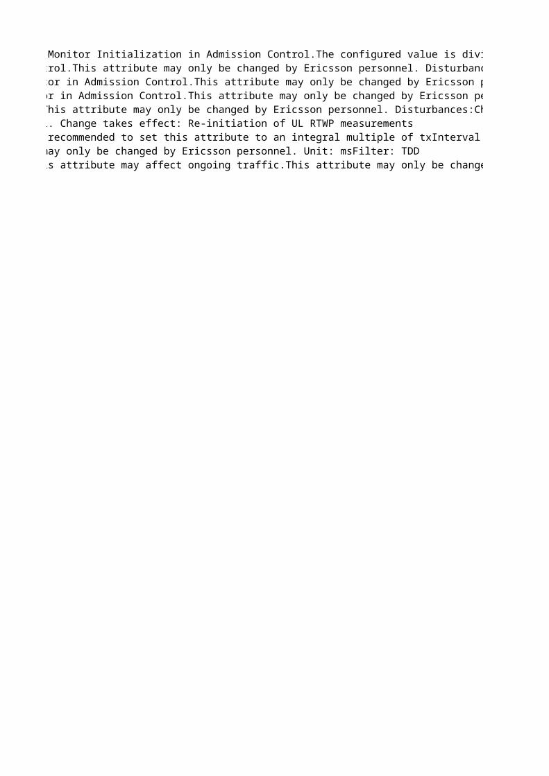
Defines the periodicity of the DL cell carrier power measurement reporting.Used by CellLoad Monitor Initialization in Admission Control.The configured value is divided by 10 by the RNC traffic application before it is sent on NBAP to RBS.This attribute may only be changed by Ericsson personnel. Disturbances:Changing this attribute may affect ongoing traffic.Unit: msResolution: 100Change takes effect: Re-initiation of Admission Control measurementsDefines the RBS internal filtering.Used by CellLoad Monitor Initialization in Admission Control.This attribute may only be changed by Ericsson personnel. Disturbances:Changing this attribute may affect ongoing traffic.Change takes effect: Re-initiation of Admission Control measurementsAttack factor for filtering the measured/estimated power consumption.Used by Cell Load Monitor in Admission Control.This attribute may only be changed by Ericsson personnel. Disturbances:Changing this attribute may affect ongoing traffic. Whenever its value is set, the cell is disabled automatically and then re-enabled.Change takes effect: Object disabled/enabledUnit: %Decay factor for filtering the measured/estimated power consumption.Used by Cell Load Monitor in Admission Control.This attribute may only be changed by Ericsson personnel. Unit: %Change takes effect: ImmediatelyFactor to take the flexibility of the TFS for a DCH into account when calculating the ASE. This attribute may only be changed by Ericsson personnel. Disturbances:Changing this attribute may affect ongoing traffic. Whenever its value is set, the cell is disabled automatically and then re-enabled.Change takes effect: Object disabled/enabledUnit: 0.01
Reporting interval for transmitted carrier power measurements between reports A and B.It is recommended to set this attribute to an integral multiple of txInterval (in ms).This attribute may only be changed by Ericsson personnel. Unit: 10 msFilter: TDD
Scaling factor for the estimation of the DL power consumption per RL. Unit: 0.01Changing this attribute may affect ongoing traffic.This attribute may only be changed by Ericsson personnel. Filter: TDD
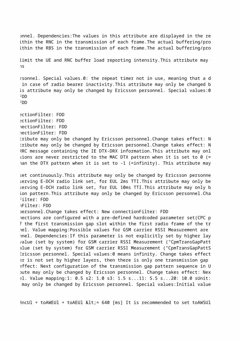
System default ARP values used when the ARP mapping feature is not activated through its RncFeature MO instance.This attribute may only be changed by Ericsson personnel. Dependencies:The values in this attribute are displayed in the read-only attribute systemDefaultArpQosFilter: FDDBuffering/processing time in the RNC for a FACH/PCH data frame on the downlink. Part of the Downlink Offset (DO). Should be set to the upper limit of the delay within the RNC in the transmission of each frame.The actual buffering/processing time is affected by the type of traffic frame (transport block type) as well as load, processing type, etc. If this value is set too low, frames may be lost or discarded (due to too-late arrival).This attribute may only be changed by Ericsson personnel. Unit: msBuffering/processing time in the RBS for a FACH/PCH data frame on the downlink. Part of the Downlink Offset (DO). Should be set to the upper limit of the delay within the RBS in the transmission of each frame.The actual buffering/processing time is affected by the type of traffic frame (transport block type) as well as load, processing type, etc. If this value is set too low, frames may be lost or discarded (due to "too late" arrival).This attribute may only be changed by Ericsson personnel. Unit: ms
Time after a channel switch is requested, after which the next measurement report may be sent from either the UE or RNC internal buffer load measurements. Used to limit the UE and RNC buffer load reporting intensity.This attribute may only be changed by Ericsson personnel. Value mapping:0: 0.25 s1: 0.5 s2: 1 s3: 2 s4: 4 s5: 8 s6: 16 sChange takes effect: New connections
Time between repeated requests to downswitch a downlink radio bearer on DCH with bad coverage to a lower DCH rate.This attribute may only be changed by Ericsson personnel. Special values.0: the repeat timer not in use, meaning that a downswitch request will not be repeatedValue mapping:1: 50 ms...4: 200 ms...40: 2000msUnit: 50 msChange takes effect: New connectionsControls whether it is allowed to switch the radio connection from a dedicated transport channel to a common transport channel (RACH/FACH) during channel switching in case of radio bearer inactivity.This attribute may only be changed by Ericsson personnel. Value mapping:0: Transition to common channel (RACH/FACH) is not allowed1: Transition to common channel (RACH/FACH) is allowedChange takes effect: New connectionsTime after which an IU RELEASE REQUEST message is sent to the core network, for UEs that only use one or two signaling connections and no RABs in state CELL_DCH.This attribute may only be changed by Ericsson personnel. Special values:0: do not release (no need to start measurements or algorithm)Unit: sChange takes effect: New connections
Number of slots in the long preamble associated with DTX cycle 2 Note, when this parameter is set to 2, RNC excludes the IE "UE DTX long preamble length" from the RRC message containing the IE DTX-DRX information.This attribute may only be changed by Ericsson personnel.Change takes effect: New connectionFilter: FDDNumber of consecutive E-DCH TTIs without an E-DCH transmission, after which the UE E-DCH transmissions are restricted to the MAC DTX pattern. The UE E-DCH transmissions are never restricted to the MAC DTX pattern when it is set to 0 (=infinity).This attribute may only be changed by Ericsson personnel.Change takes effect: New connectionFilter: FDDNumber of subframes after an HS-DSCH reception during which the CQI reports have higher priority than the DTX pattern The CQI reports always have higher priority than the DTX pattern when it is set to -1 (=infinity). This attribute may only be changed by Ericsson personnel.Change takes effect: New connectionFilter: FDD
Number of subframes after an HS-SCCH reception or after the first slot of an HS-PDSCH reception during which the UE shall monitor the HS-SCCHs in the UE's HS-SCCH set continuously.This attribute may only be changed by Ericsson personnel.Change takes effect: New connectionFilter: FDDNumber of TTIs after an E-DCH transmission during which the UE shall monitor the E-AGCH transmissions from the serving E-DCH cell and the E-RGCH from cells in the serving E-DCH radio link set, for EUL 2ms TTI.This attribute may only be changed by Ericsson personnel.Change takes effect: New connectionFilter: FDDNumber of TTIs after an E-DCH transmission during which the UE shall monitor the E-AGCH transmissions from the serving E-DCH cell and the E-RGCH from cells in the serving E-DCH radio link set, for EUL 10ms TTI.This attribute may only be changed by Ericsson personnel.Change takes effect: New connectionFilter: FDDDetermines whether the UE is required to monitor the E-AGCH and the E-RGCH when the subframe (2msTTI) or frame (10ms TTI) overlaps with the start of the DRX reception pattern.This attribute may only be changed by Ericsson personnel.Change takes effect: New connectionFilter: FDD
Parameter to determine whether the pre-defined hardcoded parameter set(profile) is used or not to configure the CPC connections. If it is set to "OFF", the CPC connections are configured with a pre-defined hardcoded parameter set(CPC profile). If ON, the static configuration associated with the CPC profile is overridden by the values set for the parameters of the MO CPC.This attribute may only be changed by Ericsson personnel.Change takes effect: New connectionFilter: FDDTransmission gap starting slot number. A transmission gap pattern begins in a radio frame, containing at least one transmission gap slot. TGSN is the slot number of the first transmission gap slot within the first radio frame of the transmission gap pattern. This attribute may only be changed by Ericsson personnel. Change takes effect: Next configuration of the transmission gap pattern sequence in UE, DRNC or RBS.Transmission gap length 1. Number of slots in the first transmission gap within the transmission gap pattern. This attribute may only be changed by Ericsson personnel. Value mapping:Possible values for GSM carrier RSSI Measurement are 3, 4, 5, 7, 10, 14.Possible values for Initial BSIC identification are 7, 10, 14.Possible values for BSIC re-confirmation are 7, 10, 14.Possible values for Inter Frequency measurements are 7, 10, 14.Since the value ranges are different for each pattern sequence, the system will not check the range. It is the responsibility of the user (Ericsson personnel) to check the range when configuring the parameter. Change takes effect: Next configuration of the transmission gap pattern sequence in UE, DRNC or RBS.Transmission gap length 2. Number of slots in the second transmission gap within the transmission gap pattern. This attribute may only be changed by Ericsson personnel. Dependencies:If this parameter is not explicitly set by higher layers, then tGL2 = tGL1. Value mapping:Possible values for GSM carrier RSSI Measurement are 3, 4, 5, 7, 10, 14.Possible values for Initial BSIC identification are 7, 10, 14.Possible values for BSIC re-confirmation are 7, 10, 14.Possible values for Inter Frequency measurements are 7, 10, 14.Since the value ranges are different for each pattern sequence, the system will not check the range. It is the responsibility of the user (Ericsson personnel) to check the range when configuring the parameter. Change takes effect: Next configuration of the transmission gap pattern sequence in UE, DRNC or RBS.Transmission gap pattern length 1. Number of frames in transmission gap pattern 1.This attribute may only be changed by Ericsson personnel. Special values:Initial value (set by system) for GSM carrier RSSI Measurement ("CpmTransGapPattSeq=1") is 8.Initial value (set by system) for Initial BSIC identification ("CpmTransGapPattSeq=2") is 8.Initial value (set by system) for BSIC re-confirmation ("CpmTransGapPattSeq=3") is 8.Initial value (set by system) for Inter Frequency measurements ("CpmTransGapPattSeq=4") is 4.Value mapping:Possible value for GSM carrier RSSI Measurement is 8.Possible values for Initial BSIC identification are 3, 4, 8, 12, 24.Possible values for BSIC re-confirmation are 3, 4, 8, 12, 15, 23, 24.Possible values for Inter Frequency measurements are 3, 4, 8, 12, 24, 35.Since the value ranges are different for each pattern sequence, the system will only check that the value is within the full range defined for the parameter. There is no check that a value for a specific sequence is within the range for that sequence. For example, the value 23 will be accepted for Initial BSIC identification. It is the responsibility of the user (Ericsson personnel) to check that the value for a specific sequence is within the range of that sequence when configuring the parameter. Change takes effect: Next configuration of the transmission gap pattern sequence in UE, DRNC or RBS.Transmission gap pattern length 2. Numer of frames in transmission gap pattern 2.This attribute may only be changed by Ericsson personnel. Special values:Initial value (set by system) for GSM carrier RSSI Measurement ("CpmTransGapPattSeq=1") is 8.Initial value (set by system) for Initial BSIC identification ("CpmTransGapPattSeq=2") is 8.Initial value (set by system) for BSIC re-confirmation ("CpmTransGapPattSeq=3") is 8.Initial value (set by system) for Inter Frequency measurements ("CpmTransGapPattSeq=4") is 4.Dependencies:It is up to the user (Ericsson personnel) to make sure tGLP1 = tGPL2 for subsequent changes during operation. There is no check in the code for this.Value mapping:Possible value for GSM carrier RSSI Measurement is 8.Possible values for Initial BSIC identification are 3, 4, 8, 12, 24.Possible values for BSIC re-confirmation are 3, 4, 8, 12, 15, 23, 24.Possible values for Inter Frequency measurements are 3, 4, 8, 12, 24, 35.Since the value ranges are different for each pattern sequence, the system will only check that the value is within the full range defined for the parameter. There is no check that a value for a specific sequence is within the range for that sequence. For example, the value 23 will be accepted for Initial BSIC identification. It is the responsibility of the user (Ericsson personnel) to check that the value for a specific sequence is within the range of that sequence when configuring the parameter. Change takes effect: Next configuration of the transmission gap pattern sequence in UE, DRNC or RBS.Transmission gap pattern repetition count. Number of transmission gap patterns within the transmission gap pattern sequence. This attribute may only be changed by Ericsson personnel. Special values:0 means infinity. Change takes effect: Next configuration of the transmission gap pattern sequence in UE, DRNC or RBS.Transmission gap start distance. Number of slots between the starting slots of two consecutive transmission gaps within a transmission gap pattern. If this parameter is not set by higher layers, then there is only one transmission gap in the transmission gap pattern. If there is only one transmission gap in the transmission gap pattern, this parameter shall be set to 0.This attribute may only be changed by Ericsson personnel. Special values:0 means undefinedChange takes effect: Next configuration of the transmission gap pattern sequence in UE, DRNC or RBS.
Maximum number of pattern repeats that the UE shall use to attempt to decode the unknown BSIC of a GSM cell in the initial BSIC identification procedure.This attribute may only be changed by Ericsson personnel. Change takes effect: Next configuration of the transmission gap pattern sequence in UE, DRNC or RBS.Maximum time allowed for the re-confirmation of the BSIC of a GSM cell in the BSIC re-confirmation procedure.This attribute may only be changed by Ericsson personnel. Value mapping:1: 0.5 s2: 1.0 s3: 1.5 s...11: 5.5 s...20: 10.0 sUnit: 0.5 sChange takes effect: Next configuration of the transmission gap pattern sequence in UE, DRNC or RBS.Offset to the transmission gap connection frame number, for the pattern sequence when starting CPM.TGCFN = running CFN + startCFNoffset + TGCFNoffsetThis attribute may only be changed by Ericsson personnel. Special values:Initial value (set by system) for GSM carrier RSSI measurement ("CpmTransGapPattSeq=1") is 0.Initial value (set by system) for Initial BSIC identification ("CpmTransGapPattSeq=2") is 2.Initial value (set by system) for BSIC reconfirmation ("CpmTransGapPattSeq=3") is 6.Initial value (set by system) for Inter Frequency measurements ("CpmTransGapPattSeq=4") is 0.Change takes effect: Next configuration of the transmission gap pattern sequence in UE, DRNC or RBS.
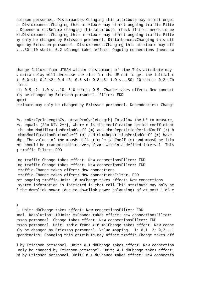
Maximum amount of puncturing for common channels.Value mapping:0: 40 %1: 44 %2: 48 %...15: 100 %This attribute may only be changed by Ericsson personnel.Dependencies:Before changing this attribute, check if tfcs needs to be changed as well. If so, lock the parent UtranCell manually before changing both.Disturbances:Changing this attribute may affect ongoing traffic.Unit: 4 %Filter: TDDReplaces: tdSccpchPunctureLimit
Rate matching attribute in the downlink for the first FACH. The first FACH is used for logical channels BCCH, CCCH and DCCH, for control signaling.This attribute may only be changed by Ericsson personnel. Disturbances:Changing this attribute may affect ongoing traffic.Dependencies:Before changing this attribute, check if tfcs needs to be changed as well. If so, lock the parent UtranCell manually before changing both. Filter: TDDRate matching attribute in the downlink for the second FACH. The second FACH is used for logical channel DTCH, for traffic signaling.This attribute may only be changed by Ericsson personnel. Disturbances:Changing this attribute may affect ongoing traffic.Dependencies:Before changing this attribute, check if tfcs needs to be changed as well. If so, lock the parent UtranCell manually before changing both.Filter: TDD
Time for supervising the "move" from UTRAN to GSM.Once the cell change order from UTRAN has been sent, the system expects to receive an Iu release command or Cell change failure from UTRAN within this amount of time.This attribute may only be changed by Ericsson personnel. Unit: sChange takes effect: New connectionsWhen the connection is set up for the first time, Measurement handler function will wait this predetermined time before it sends the first cell list to the UE. This extra delay will decrease the risk for the UE not to get the initial cell list , since initially it is busy to get synchronized to UTRAN.This attribute may only be changed by Ericsson personnel. Unit: sChange takes effect: Ongoing connectionsTime interval between trials to initiate compressed mode. This attribute may only be changed by Ericsson personnel. Special values:0 means no retry. Value mapping:0: 0.0 s1: 0.2 s2: 0.4 s3: 0.6 s4: 0.8 s5: 1.0 s...50: 10 sUnit: 0.2 sChange takes effect: Ongoing connections (next switch to CELL_DCH)Filter: FDD
Downlink TPC pattern transmitted for the first RLS, until uplink initial synchronization is achieved. This parameter is used for the NBAP cell setup message.This attribute may only be changed by Ericsson personnel. Dependencies: Changing this attribute may affect ongoing traffic.
Represents m, the modification period coefficient. The actual modification period (MP), in number of frames, equals 2^m.m >= k, where k = max[cnDrxCycleLengthPs, cnDrxCycleLengthCs, utranDrxCycleLength] To allow the UE to measure, when applicable, on another frequency when reading MCCH there has to be some gaps in the MCCH transmission (the MP shall not be fully utilized). Note: The UE and SGSN can negotiate the value of the cnDrxCycleLengthPs. This case can not be handled by the system. This attribute may only be changed by Ericsson personnel.Change takes effect: At MbmsCch lock/unlock and at system restartRepresents r, the repetition period coefficient. The number of repetitions per modification period equals 2^r while the actual repetition period, in number of frames, equals [2^m DIV 2^r], where m is the modification period coefficient.[2^m DIV 2^r] >= nrOfRrcFrames, where nrOfRrcFrames defines the number of frames the MCCH information requires in each Repetition Period. (Note: nrOfRrcFrames is not a parameter but only a definition in the above equation.)This attribute may only be changed by Ericsson personnel.Change takes effect: At MbmsCch lock/unlock and at system restartMaximum number of simultaneous ongoing MBMS sessions in one non-PL cell. The MCCH FACH with TTI 20 ms for S-CCPCH has maximum user data rate 7.6 kbps.The values of the mbmsModificationPeriodCoeff (m) and mbmsRepetitionPeriodCoeff (r) have dependencies to the number of frames that can be scheduled per Repetition Period on MCCH with the data rate 7.6 kbps. Parameters nonPlSessionsMax, plSessionsMax and neighbourCellsMax put limits on number of frames to be scheduled in a worst case scenario.It must be considered when changing any of the above parameters that the number of frames to be scheduled on MCCH for RRC messages does not exceed the number of frames that can be scheduled per Repetition Period on MCCH.This attribute may only be changed by Ericsson personnel.Change takes effect: At MbmsCch lock/unlock and at system restartFilter: FDDMaximum number of simultaneous ongoing MBMS sessions in one PL cell. The MCCH FACH with TTI 20 ms for S-CCPCH has maximum user data rate 7.6 kbps.The values of the mbmsModificationPeriodCoeff (m) and mbmsRepetitionPeriodCoeff (r) have dependencies to the number of frames that can be scheduled per Repetition Period on MCCH with the data rate 7.6 kbps. Parameters nonPlSessionsMax, plSessionsMax and neighbourCellsMax put limits on number of frames to be scheduled in a worst case scenario.It must be considered when changing any of the above parameters that the number of frames to be scheduled on MCCH for RRC messages does not exceed the number of frames that can be scheduled per Repetition Period on MCCH.This attribute may only be changed by Ericsson personnel.Change takes effect: At MbmsCch lock/unlock and at system restartMaximum number of intra-frequency neighboring cells for which information is sent on MCCH. The MCCH FACH with TTI 20 ms for S-CCPCH has maximum user data rate 7.6 kbps.The values of the mbmsModificationPeriodCoeff (m) and mbmsRepetitionPeriodCoeff (r) have dependencies to the number of frames that can be scheduled per Repetition Period on MCCH with the data rate 7.6 kbps. Parameters nonPlSessionsMax, plSessionsMax and neighbourCellsMax put limits on number of frames to be scheduled in a worst case scenario.It must be considered when changing any of the above parameters that the number of frames to be scheduled on MCCH for RRC messages does not exceed the number of frames that can be scheduled per Repetition Period on MCCH.This attribute may only be changed by Ericsson personnel.Change takes effect: At MbmsCch lock/unlock and at system restartBCCH modification cycle length coefficient (k). The cycle length is calculated as the k'th potential of 2, where k = 6,..,9. The BCCH modification information element should be transmitted in every frame within a defined interval. This interval will be within a specific cycle interval similarly defined as DRX cycle length.Special values:Initially set by the system to 9 (corresponds to cycle length 5,120 s).This attribute may only be changed by Ericsson personnel.
If the difference between reported power measurement and the power value transmitted in System Information is larger than this hysteresis in one cell, an update of system information is initiated in that cell.This attribute may only be changed by Ericsson personnel. Value mapping:30: 3.0 dB31: 3.1 dB...60: 6.0 dBUnit: 0.1 dBFilter: FDDMaximum adjustment step for downlink power balancing.This parameter is signaled over NBAP with the values [1..10] slots, where 1 corresponds to an allowed change of the downlink power (due to downlink power balancing) of at most 1 dB every 1 slot. 10 corresponds to an allowed change of the downlink power of at most 1 dB every 10 slots.maxAdjustmentStep = 1 corresponds to a limit on rate of change of 1 dB/slot.maxAdjustmentStep = 10 corresponds to a limit on rate of change of 0.1 dB/slot.This attribute may only be changed by Ericsson personnel. Change takes effect: New connectionsFilter: FDD
The jump algorithm typically gives a result that is slightly biased towards increased BLER. This parameter is used to compensate for this bias.This attribute may only be changed by Ericsson personnel. Value mapping: 1: 0,1 2: 0,2...10: 1,0Change takes effect: New connectionsMeasurement Filter Coefficient for Transmitted Code Power measurement used for downlink power balancing.This attribute may only be changed by Ericsson personnel. Dependencies: Changing this attribute may affect traffic.Change takes effect: New connectionsFilter: FDD
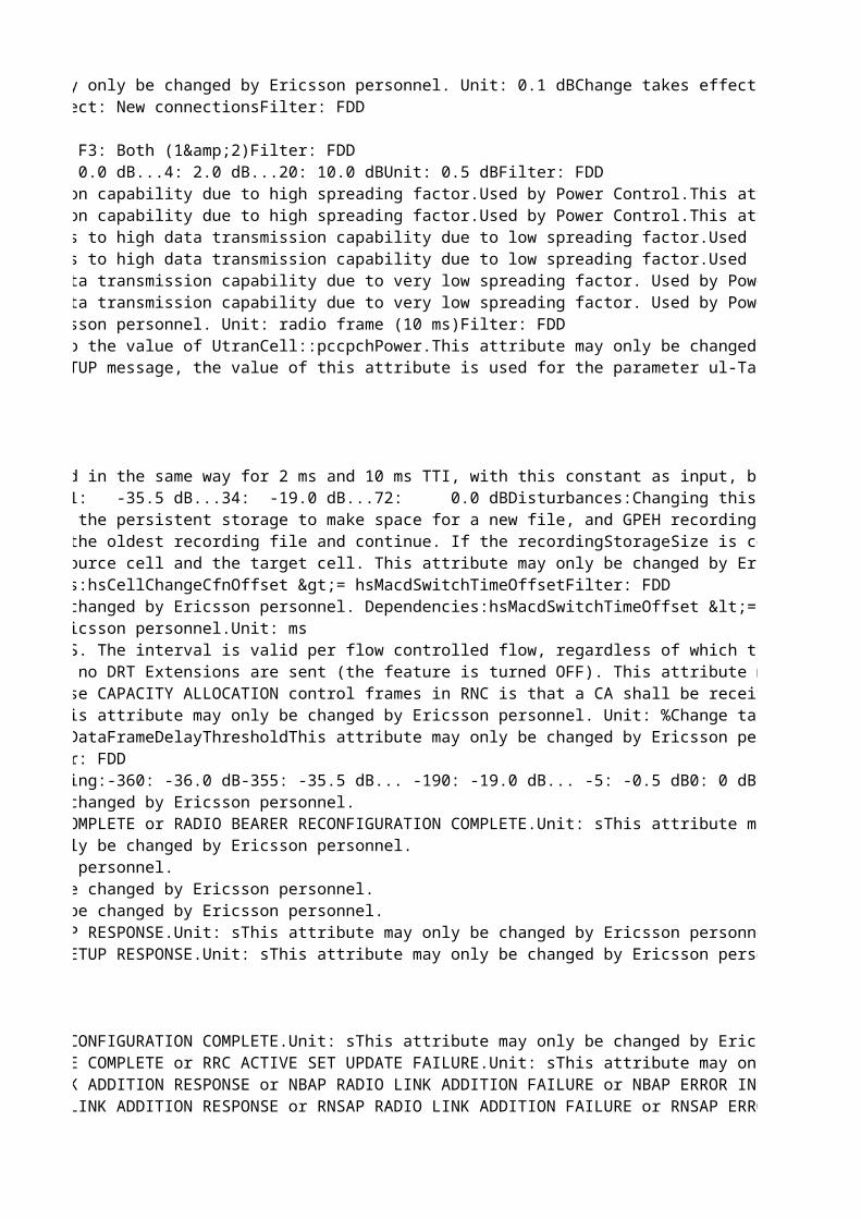
Reference gain factor (generic beta value) for the uplink DPCCH part of RABs (or SRB) with a minimum spreading factor >= 32. 'Low' refers to low data transmission capability due to high spreading factor.Used by Power Control.This attribute may only be changed by Ericsson personnel. Dependencies:Note that either gainFactorCLow or gainFactorDLow must be equal to 15.Filter: FDDReference gain factor (generic beta value) for the uplink DPDCH part of RABs (or SRB) with a minimum spreading factor >= 32. 'Low' refers to low data transmission capability due to high spreading factor.Used by Power Control.This attribute may only be changed by Ericsson personnel. Dependencies:Note that either gainFactorCLow or gainFactorDLow must be equal to 15.Reference gain factor (generic beta value) for the uplink DPCCH part of RABs (or SRB) with a minimum spreading factor in the range 8 < SF <= 16. 'High' refers to high data transmission capability due to low spreading factor.Used by Power Control.This attribute may only be changed by Ericsson personnel. Dependencies:Note that either gainFactorCHigh or gainFactorDHigh must be equal to 15.Filter: FDDReference gain factor (generic beta value) for the uplink DPDCH part of RABs (or SRB) with a minimum spreading factor in the range 8 < SF <= 16. 'High' refers to high data transmission capability due to low spreading factor.Used by Power Control.This attribute may only be changed by Ericsson personnel. Dependencies:Note that either gainFactorCHigh or gainFactorDHigh must be equal to 15.Reference gain factor (generic beta value) for the uplink DPCCH part of RABs (or SRB) with a minimum spreading factor <= 8. 'Extra high' refers to extra high data transmission capability due to very low spreading factor. Used by Power Control.This attribute may only be changed by Ericsson personnel. Dependencies:gainFactorCExtraHigh or gainFactorDExtraHigh must be equal to 15Reference gain factor (generic beta value) for the uplink DPDCH part of RABs (or SRB) with a minimum spreading factor <= 8. 'Extra high' refers to extra high data transmission capability due to very low spreading factor. Used by Power Control.This attribute may only be changed by Ericsson personnel. Dependencies:gainFactorCExtraHigh or gainFactorDExtraHigh must be equal to 15Filter: FDD
Default initial downlink transmission power, used when the PCCPCH RSCP or downlink time slot ISCP is not received from the measurement report. Expressed relative to the value of UtranCell::pccpchPower.This attribute may only be changed by Ericsson personnel.Unit: 0.1 dBFilter: TDDReplaces: tdDefaultInitDlTransPowerDefault initial desired received uplink DPCH power value, used when the uplink time slot ISCP is not received from the measurement report. In the RRC CONNECTION SETUP message, the value of this attribute is used for the parameter ul-TargetSIR.This attribute may only be changed by Ericsson personnel.Unit: dBmFilter: TDDReplaces: tdDefaultPrxDpchDes
The pre-allocated hardware rate for scheduled data for E-DCH users in the RBS. Needed for RBS hardware consumption calculations in RNC. The calculation is performed in the same way for 2 ms and 10 ms TTI, with this constant as input, but the values shall then be rounded up differently depending on the used TTI. This attribute may only be changed by Ericsson personnel. Dependencies: The same constant is defined in the RBS for the scheduler. These constants should be set to the same value. Unit: kbps (1000 bits per second)Resolution: 32Change takes effect: Ongoing connectionsFilter: FDDThe threshold for preamble detection, relative to the interference level. This attribute may only be changed by Ericsson personnel. Value mapping: 0: -36.0 dB 1: -35.5 dB...34: -19.0 dB...72: 0.0 dBDisturbances:Changing this attribute may affect ongoing traffic.Unit: 0.5 dBFilter: FDDTotal GPEH storage size available on the O&M MP and each Module MP.When gpehStorageSize is exceeded, the GPEH function will remove the oldest GPEH file(s) from the persistent storage to make space for a new file, and GPEH recording will continue.This attribute may only be changed by Ericsson personnel.Dependencies: The size of the GPEH file may never exceed the available GPEH storage size on each MP (gpehStorageSize >= gpehFileSize).Unit: kB (1000 bytes)Change takes affect: Next ROPTotal size of the storage space available for PM Recording ROP files on the O&M MP.When recordingStorageSize is reached, the PM Recording function will remove the oldest recording file and continue. If the recordingStorageSize is completely used by a single recording file, the PM Recording function will stop the recording until the next ROP begins.This attribute may only be changed by Ericsson personnel. Dependencies: The file sizes for UETR and CTR recordings may never exceed the available recording storage size on the central O&M MP: recordingStorageSize >= ctrFileSize, recordingStorageSize >= uetrFileSizeUnit: kB (1000 bytes)Change takes effect: Next ROPThreshold below which RRC redirections for inter-frequency load sharing will be inhibited. Defined in terms of the difference in available resources between the source cell and the target cell. This attribute may only be changed by Ericsson personnel. Unit: %Change takes effect: Immediately
Used when calculating the time for the switch-over of the HS MAC-D flow from Source Cell to Target Cell, at Serving HS-DSCH Cell Change.This attribute may only be changed by Ericsson personnel. Dependencies:hsMacdSwitchTimeOffset <= hsCellChangeCfnOffsetUnit: frame
Defines the minimum interval between two consecutive TNL CONGESTION INDICATION control frames, belonging to one flow controlled EUL flow, which are sent towards RBS. The interval is valid per flow controlled flow, regardless of which type of TCI that are sent, e.g. with code 2 or 3. This attribute may only be changed by Ericsson personnel. Unit: msResolution: 50Minimum time interval between two HS-DSCH Data Frames with a DRT Extension. The purpose is to not send DRT Extensions too often. When the parameter is set to zero, no DRT Extensions are sent (the feature is turned OFF). This attribute may only be changed by Ericsson personnel. Unit: msResolution: 10Change takes effect: New connectionsTime without a received CAPACITY ALLOCATION (CA) control frame, for this PQF, that results in a reduced HSDPA bit rate. The reason for checking the presence of these CAPACITY ALLOCATION control frames in RNC is that a CA shall be received at least every one second time interval (more often or once per second). If this doesn't happen, it is likely that a CA is dropped over the transport network. Further on, if several CA control frames are dropped, not received in RNC, it could mean that the best effort type of transport network is congested. This attribute may only be changed by Ericsson personnel. Special values:0 defines that CA presence supervision is turned off.Unit: 0.1 sChange takes effect: New connectionsDefines the degree of bit rate reduction due to missing CAPACITY ALLOCATION control frames.Example: New bit rate = Old bit rate * (1- hsMissingCaReduction/100). This attribute may only be changed by Ericsson personnel. Unit: %Change takes effect: New connections
Indicates the preamble threshold to be used when the feature Increased RACH Coverage is active.This attribute may only be changed by Ericsson personnel. Value mapping:-360: -36.0 dB-355: -35.5 dB... -190: -19.0 dB... -5: -0.5 dB0: 0 dBUnit: 0.1 dBResolution: 5Change takes effect: ImmediatelyFilter: FDD
Started at transmission of RRC: TRANSPORT CHANNEL RECONFIGURATION or RADIO BEARER RECONFIGURATION. Stopped at reception of RRC: TRANSPORT CHANNEL RECONFIGURATION COMPLETE or RADIO BEARER RECONFIGURATION COMPLETE.Unit: sThis attribute may only be changed by Ericsson personnel.
Started at transmission of RRC: RADIO BEARER RELEASE or RADIO BEARER RECONFIGURATION. Stopped at reception of RRC: RADIO BEARER RELEASE COMPLETE or RADIO BEARER RECONFIGURATION COMPLETE.Unit: sThis attribute may only be changed by Ericsson personnel. Timer used to supervise the RRC Active Set Update procedure. Started at transmission of RRC ACTIVE SET UPDATE REQUEST. Stopped at reception of RRC ACTIVE SET UPDATE COMPLETE or RRC ACTIVE SET UPDATE FAILURE.Unit: sThis attribute may only be changed by Ericsson personnel. Timer used to supervise the NBAP Radio Link Addition procedure. Started at transmission of NBAP RADIO LINK ADDITION REQUEST. Stopped at reception of NBAP RADIO LINK ADDITION RESPONSE or NBAP RADIO LINK ADDITION FAILURE or NBAP ERROR INDICATION.Unit: sThis attribute may only be changed by Ericsson personnel. Timer used to supervise the RNSAP Radio Link Addition procedure. Started at transmission of RNSAP RADIO LINK ADDITION REQUEST. Stopped at reception of RNSAP RADIO LINK ADDITION RESPONSE or RNSAP RADIO LINK ADDITION FAILURE or RNSAP ERROR INDICATION.Unit: sThis attribute may only be changed by Ericsson personnel.
Time for supervision of RRC Connection Setup.Used by the UE.This attribute may only be changed by Ericsson personnel. Value mapping:0: 100 ms1: 200 ms2: 400 ms3: 600 ms4: 800 ms5: 1000 ms6: 1200 ms7: 1400 ms8: 1600 ms9: 1800 ms10: 2000 ms11: 3000 ms12: 4000 ms13: 6000 ms14: 8000 msChange takes effect: New connectionsMaximum time between UE transmission of Cell Update message and UE reception of the Cell Update Confirm message. If not received, the UE sends a new Cell Update. This attribute may only be changed by Ericsson personnel. 0: 100 ms1: 200 ms2: 400 ms3: 600 ms4: 800 ms5: 1000 ms6: 1200 ms7: 1400 ms8: 1600 ms9: 1800 ms10: 2000 ms11: 3000 ms12: 4000 ms13: 6000 ms14: 8000 ms
The TTI Alignment (UL and 2*DL) and UE Processing delay in number of radio frames added to the activation time (i.e. the CFN) calculated by the RNC using SRB on DCH-DL. This system constant can be calculated in the following way: cfnOffsetSrbDchDl = 2*TTI_Alignment_DL + TTI_Alignment_UL + UE_Processing_UL_and_DL Default value is calculated as: 2*4+4+6=18 radio frames Unit: 10 msChange takes effect: At next synchronized reconfiguration of the connection This attribute may only be changed by Ericsson personnel. TTI alignment and UE Processing delay in number of radio frames added to the activation time (i.e. the CFN) calculated by the RNC using SRB on HS. This system constant can be calculated in the following way: cfnOffsetSrbHs = TTI_Alignment_DL+ TTI_Alignment_UL+ UE_Processing_UL_and_DL Default value is calculated as: 2+10+60ms=72ms=8 radio framesUnit: 10 msChange takes effect: At next synchronized reconfiguration of the connection.This attribute may only be changed by Ericsson personnel.
Applicable when more than one SDU Format exists per subflow and more than one subflow exists for one rabType. It is used to create a subflow combination with the correct sduSize parameters e.g. SID + an AMR rate.This attribute may only be changed by Ericsson personnel.
Cell synch information report indicator. Indicates if cell synchronization information shall be reported for cells in the detected set. This attribute may only be changed by Ericsson personnel. Value mapping:0: False1: TrueChange takes effect: Ongoing connections (next switch to CELL_DCH)Filter: FDD
Indicates which set of the cells shall be used in event 1a reporting evaluation. This attribute may only be changed by Ericsson personnel. Value mapping:2 : Monitored set cells4 : Detected set cells5 : Detected set cells and monitored set cellsChange takes effect: Ongoing connections (next switch to CELL_DCH)Filter: FDDNumber of reports when UE has reverted to event-triggered periodical reporting due to 'cell addition failure', for event type 1a.Used by UE functions for intra-frequency measurement reporting (in CELL_DCH). This attribute may only be changed by Ericsson personnel. Value mapping:0: 11: 22: 4...6: 647: infinityChange takes effect: Ongoing connections (next switch to CELL_DCH)Filter: FDDMaximum number of cells included in the report for event 1a. This attribute may only be changed by Ericsson personnel. Value mapping:1 : Virtual/Active set cells + 12 : Virtual/Active set cells + 23 : Virtual/Active set cells + 34 : Virtual/Active set cells + 45 : Virtual/Active set cells + 56 : Virtual/Active set cells + 6Change takes effect: Ongoing connections (next switch to CELL_DCH)Filter: FDD
Maximum number of periodic reports at event-triggered periodic reporting for event 1c. This attribute may only be changed by Ericsson personnel. Value mapping:0: 11: 22: 4...6: 647: infinityChange takes effect: Ongoing connections (next switch to CELL_DCH)Filter: FDDMaximum number of cells included in the report for event 1c. This attribute may only be changed by Ericsson personnel. Value mapping:1 : Virtual/Active set cells + 12 : Virtual/Active set cells + 23 : Virtual/Active set cells + 34 : Virtual/Active set cells + 45 : Virtual/Active set cells + 56 : Virtual/Active set cells + 6Change takes effect: Ongoing connections (next switch to CELL_DCH)Filter: FDD
Maximum number of cells included in the report for event 1d. This attribute may only be changed by Ericsson personnel. Value mapping:1: Virtual/Active set cells + 12: Virtual/Active set cells + 23: Virtual/Active set cells + 34: Virtual/Active set cells + 45: Virtual/Active set cells + 56: Virtual/Active set cells + 6Change takes effect: Ongoing connections (next switch to CELL_DCH)Filter: FDD
Indicates if cell synchronization information shall be reported for cells in the Virtual Active Set(s), for measurement 4 event 2b.This attribute may only be changed by Ericsson personnel. Change takes effect: Ongoing connections (next time that inter-frequency measurements are started)Filter: FDDIndicates if UE autonomous update of the Virtual Active Set(s) shall be done or not, for measurement 4 event 2b.This attribute may only be changed by Ericsson personnel. Change takes effect: Ongoing connections (next time that inter-frequency measurements are started)Filter: FDDMaximum number of cells per reported non-used frequency included in the report for measurement 4 event 2b.This attribute may only be changed by Ericsson personnel. Change takes effect: Ongoing connections (next time that inter-frequency measurements are started)
Transfer delay. Indicates maximum delay for 95th percentile of the distribution of delivered SDUs during the lifetime of a bearer service, where delay for an SDU is defined as the time from a request to transfer of an SDU at one SAP to its delivery to the other SAP.Used to specify the delay tolerated by the application. It allows UTRAN to set transport formats and ARQ parameters.This attribute may only be changed by Ericsson personnel. Unit: ms
Time to wait for CN response to an Iu-c initialization procedure. After this length of time, if no response has been received, RNC repeats the initialization procedure. The maximum number of repeated attempts is defined in noIucInitRep.This attribute may only be changed by Ericsson personnel. Special values:0 is used to indicate that iucInitTimer is not in use.Unit: sChange takes effect: New connections
Deprecated: This attribute is currently not used by the system. Changing it has no effect.Used to determine the value to which IE Activation Time (RRC) and IE CFN (RNSAP and NBAP) shall be set when starting compressed mode.This attribute may only be changed by Ericsson personnel. Value mapping:1: 752: 1203: 150Change takes effect: Next configuration of the transmission gap pattern sequence in UE, DRNC or RBS.Used to determine the value to which IE CM Configuration Change CFN (RNSAP and NBAP) and TGPS reconfiguration CFN (RRC) shall be set when stopping compressed mode.This attribute may only be changed by Ericsson personnel. Value mapping:1: 1002: 1503: 200Change takes effect: Next stop of CPM
The reference TFC is the TFC from the TFCS of the configuration represented by the UeRc that has the most Transport Format information in the TFCS (the TFC that will result in the maximum number of TB's with largest size being applied).This attribute may only be changed by Ericsson personnel. Filter: TDD
Time that the re-ordering entity should wait for an outstanding MAC-es PDU.It is recommended that the value of this attribute should be the same for all flows under a specific UeRc instance.This attribute may only be changed by Ericsson personnel. Unit: msChange takes effect: New connectionsIdentifies what kind of radio bearer this MO instance represents.This attribute may only be changed by Ericsson personnel. Special values:Only the values RB_RRC, RB_PS_INTERACTIVE and RB_PS_INTERACTIVE_2 are applicable for this attribute and MO (even though the other values are allowed to be set).
MAC-hs/MAC-ehs window size used in the RBS and the UE for MAC-hs/MAC-ehs data transfer. The parameter value setting is signaled via NBAP and RRC. If MIMO or Multi-Carrier is used for a HS-DSCH connection, the value signaled is min(32, 2 * macHsWindowSize).This attribute may only be changed by Ericsson personnel.Time to live for a MAC-hs SDU starting from the instant of its arrival into an HSDPA Priority Queue. The RBS shall use this information to discard out-of-data MAC-hs SDUs from the HSDPA Priority Queues. The parameter value setting is signaled via NBAP.This attribute may only be changed by Ericsson personnel.Unit: ms
Identifies what kind of radio bearer this MO instance represents. Special values:Only the values RB_RRC, RB_PS_INTERACTIVE_HS, RB_PS_INTERACTIVE_HS_2, RB_PS_INTERACTIVE_HS_3, and RB_PS_STREAMING_HS are applicable for this attribute and MO (even though the other values are allowed to be set).This attribute may only be changed by Ericsson personnel. Filter: FDD
TFCI presence indicator. This has the same meaning as the RRC parameter "TFCI existence".DPCH info.This attribute may only be changed by Ericsson personnel. Value mapping:0: No = TFCI not present; same as "TFCI existence" = FALSE1: Yes = TFCI present; same as "TFCI existence" = TRUE
Number of pilot bits for DPCH.The number of pilot bits needs to be signaled to the UE in case the downlink physical connection uses spreading factor 128 or 256. In all other cases the UE calculates the number of pilot bits based on slot format information. The number of pilot bits is not signaled towards the RBS. For downlink physical connections using other spreading factors, the configured value will not be used by the RNC, but has to be set anyway since the parameter is defined as mandatory in the MOM. Any of the defined values will work.This attribute may only be changed by Ericsson personnel. Filter: FDD
Repetition period.This attribute may only be changed by Ericsson personnel.Value mapping:0: RepetitionPeriod_v11: RepetitionPeriod_v22: RepetitionPeriod_v43: RepetitionPeriod_v84: RepetitionPeriod_v165: RepetitionPeriod_v326: RepetitionPeriod_v64Specification: Chapter 8.6.6.16 in TS 25.331 V4.17.0 Filter: TDDReplaces: tdRepetitionPeriodNumber of radio frames to be used as the offset for the DPCH. Used for determining the frame offset from the SFN timing in a cell.This attribute may only be changed by Ericsson personnel.Disturbances:Changing this attribute will affect ongoing traffic.Filter: TDDReplaces: tdTddDpchOffsetValueDetermines the number of bits for the TFCI bits code word.Value mapping:0: v41: v82: v163: v32In case of 8 PSK in 1.28Mcps:v4 corresponds to 6 TFCI code word bits.v8 corresponds to 12 TFCI code word bits.v16 corresponds to 24 TFCI code word bits.v32 corresponds to 48 TFCI code word bits.This attribute may only be changed by Ericsson personnel.Filter: TDDReplaces: tdTfciCodingTSTD indicator. TSTD can be used to overcome the time varying characteristics of the communication channel, Similar to the IE "Tx diversity indicator" for FDD, "TSTD indicator" can be defined and used to inform the application of TSTD to DPCH.This attribute may only be changed by Ericsson personnel.Value mapping:0: active1: inactive Filter: TDDReplaces: tdTstdIndicator
Puncturing limit when increasing the number of used channelization codes. Only applies when the number of code channels is less than the maximum allowed by the UE capability and restrictions imposed by UTRAN.This attribute may only be changed by Ericsson personnel. Resolution: 4
Deprecated: This attribute is currently not used by the system. Changing it has no effect.Defines the E-DCH multiplexing option for this E-DCH radio configuration.Value mapping:0: No multiplexing except among scheduled flows.1: Multiplexing among non-scheduled flows allowed except between SRB and a non-scheduled SIP (if exists), among scheduled flows allowed, but not between scheduled and non-scheduled flows.2: All multiplexing allowed except between SRB and scheduled flows or non-scheduled SIP (if exists).3: All multiplexing allowed except between SRB and a non-scheduled SIP (if exists). This attribute may only be changed by Ericsson personnel. Minimum reduced E-DPDCH gain factor. When E-DCH is configured, if the total UE transmit power (after applying DPCCH power adjustments and gain factors) would exceed the available maximum power, the UE shall firstly reduce the E-DPDCH power with the E-DPDCH gain factor so that the total transmit power would be equal to the available maximum power. If the total transmit power is still higher than the available maximum power after applying the gain factor the E-DPDCH and the DPCCH are equally scaled to meet the available maximum power. This parameter configures the minimum factor to be used by Rel-8 UEs for reduction of the E-DPDCH gain factor. The configured value is divided by 15 to obtain the scaling factor used by the UE. -1 means that this attribute is not applicable for this instance.This attribute may only be changed by Ericsson personnel.Unit: 1 / 15 Change takes effect: Immediately
Controls which message part format the DPCH shall use as the time slot format for the first physical channel (meaning the physical channel with the least number of time slots and least number of channels). This attribute may only be changed by Ericsson personnel. Filter: TDDReplaces: tdDpchSlotFormat
Repetition period.This attribute may only be changed by Ericsson personnel.Value mapping: 0: RepetitionPeriod_v11: RepetitionPeriod_v22: RepetitionPeriod_v43: RepetitionPeriod_v84: RepetitionPeriod_v165: RepetitionPeriod_v326: RepetitionPeriod_v64Specification: Chapter 8.6.6.16 in TS 25.331 V4.17.0 Filter: TDDReplaces: tdRepetitionPeriod
Number of radio frames to be used as the offset for the DPCH. Used for determining the frame offset from the SFN timing in a cell.This attribute may only be changed by Ericsson personnel.Disturbances:Changing this attribute will affect ongoing traffic.Filter: TDDReplaces: tdTddDpchOffsetValueDetermines the number of bits for the TFCI bits code word.Value mapping: 0: v41: v82: v163: v32In case of 8 PSK in 1.28Mcps:v4 corresponds to 6 TFCI code word bits.v8 corresponds to 12 TFCI code word bits.v16 corresponds to 24 TFCI code word bits.v32 corresponds to 48 TFCI code word bits.This attribute may only be changed by Ericsson personnel.Filter: TDDReplaces: tdTfciCoding
Identifies what kind of radio bearer this MO instance represents.This attribute may only be changed by Ericsson personnel. Special values:Value RB_PACKET_ADCH, RB_PACKET_ADCH_2, RB_PACKET_ADCH_3 and RB_STREAMING_ADCH are not applicable for this attribute and MO (but are nonetheless allowed to be set).RLC Logical Channel Type.RLC info common to RNC side and UE sideThis attribute may only be changed by Ericsson personnel. Value mapping:0: DCCH Dedicated Control Ch. Valid only on DCS side1: DTCH Dedicated Traffic Ch. Valid only on DCS side2: BCCH Broadcast Control Channel. Valid only on CCS side.3: CCCH Common Control Channel. Valid only on CCS side.4: PCCH Paging Control Channel. Valid only on CCS side.
Indicates if RNC should send a STATUS report for each detected PDU missing.RLC info on RNC side. Valid only for RLC mode = AM.This attribute may only be changed by Ericsson personnel. Value mapping:0: RNC shall not send STATUS reports1: RNC shall send STATUS reports
Indicates if in-sequence delivery shall be used or not.RLC info on RNC side. Valid only for RLC mode = UM and AM.This attribute may only be changed by Ericsson personnel. Value mapping:0: the value can be configured but in-sequence delivery will still be used, that is, in-sequence delivery is predefined.1: in-sequence delivery shall be usedDetermines the number of transmissions of a PDU before a SDU is discarded or reset procedure is initiated.The maximum number of transmissions of a PDU equals MaxDat-1.RLC info on RNC side. Valid only for RLC mode = AM.This attribute may only be changed by Ericsson personnel.
Transmission SDU discard mode.RLC info on UE side UL. This attribute may only be changed by Ericsson personnel. Value mapping:0: Timer Based Explicit (can be configured but is not used)1: Timer Based No Explicit (can be configured but is not used)2: Max Dat (can be configured but is not used)3: No Discard (AM), SDU Discard not configured (TM and UM)Determines the number of transmissions of a PDU before a SDU is discarded or reset procedure is initiated.The number of transmissions is equal to MaxDat - 1.RLC info on UE side UL. Valid only for RLC mode = AM.This attribute may only be changed by Ericsson personnel. Value mapping: 2: MaxDat = 3 3: 4 4: 5 5: 6 6: 7 7: 8 8: 9 9: 1010: 1511: 2012: 2513: 3014: 3515: MaxDat = 40 Maximum number of RLC PDUs sent without getting them acknowledged. RLC info on UE side UL. Valid only for SRB with RLC mode = AM. This attribute may only be changed by Ericsson personnel. Value mapping: 0:1 Max PDU sent 1:8 2:16 3:32 4:64 5:128 6:256 7:512 8:768 9:1024 10:1536 11:2047 12:2560 13:3072 14:3584
The maximum number of transmissions of reset PDU equals MaxRst-1.RLC info on UE side UL. This attribute may only be changed by Ericsson personnel. Value mapping:0: MaxRst = 11: 42: 63: 84: 125: 166: 247: MaxRst =32
Timer poll, started when poll is transmitted. New poll is sent when timer expires and no STATUS is received.RLC polling info on UE side UL. Valid only for RLC mode = AM.This attribute may only be changed by Ericsson personnel. Special values:-1: not used 10 .. 550 ms with resolution 10600 ..1000ms with resolution 50Unit: ms
Indicates whether in-sequence delivery shall be used.It is assumed that the same value is used for both DL and UL.RLC info on UE side DL. Valid for RLC mode = AM and UM.This attribute may only be changed by Ericsson personnel. Value mapping:0: in-sequence delivery shall not be used1: in-sequence delivery shall be usedMaximum number of RLC PDUs in the receiving buffer. RLC info on UE side DL. Valid only for SRB with RLC mode = AM. This attribute may only be changed by Ericsson personnel. Value mapping: 0:1 PDU in buffer 1:8 2:16 3:32 4:64 5:128 6:256 7:512 8:768 9:1024 10:1536 11:2047 12:2560 13:3072 14:3584 15:4095
Indicates if UE should send a STATUS report for each detected PDU missing. This value is also used in DL RLC Status Info sent on RRC.RLC info on UE side DL. Valid only for RLC mode = AM.This attribute may only be changed by Ericsson personnel. Value mapping:0: UE shall not send STATUS reports1: UE shall send STATUS reports
Number of SDUs, interval between polling.This attribute may only be changed by Ericsson personnel. Value mapping:-1 Attribute not used.0 1 PDU interval 1 2 PDU interval 2 4 PDU interval 3 8 PDU interval 4 16 PDU interval 5 32 PDU interval 6 64 PDU interval 7 128 PDU interval
Determines the number of transmissions of a PDU before a SDU is discarded or reset procedure is initiated.The number of transmissions is equal to MaxDat - 1.This attribute may only be changed by Ericsson personnel. Value mapping: 2: MaxDat = 3 3: 4 4: 5 5: 6 6: 7 7: 8 8: 9 9: 1010: 1511: 2012: 2513: 3014: 3515: MaxDat = 40
Maximum number of RLC PDUs in the receiving buffer. RLC info on UE side DL. Valid only for SRB with RLC mode = AM. This attribute may only be changed by Ericsson personnel. Value mapping: 0:1 PDU in buffer 1:8 2:16 3:32 4:64 5:128 6:256 7:512 8:768 9:1024 10:1536 11:2047 12:2560 13:3072 14:3584 15:4095Timer poll, started when poll is transmitted. New poll is sent when timer expires and no STATUS is received.RLC polling info on UE side UL. Valid only for RLC mode = AM.This attribute may only be changed by Ericsson personnel. Value mapping:10 .. 550 ms with resolution 10600 ..1000ms with resolution 50Unit: ms
Maximum number of RLC PDUs sent without getting them acknowledged. RLC info on UE side UL. Valid only for RLC mode = AM.This attribute may only be changed by Ericsson personnel. Value mapping: 0:1 Max PDU sent 1:8 2:16 3:32 4:64 5:128 6:256 7:512 8:768 9:1024 10:1536 11:2047 12:2560 13:3072 14:3584
Identifies what kind of radio bearer this MO instance represents.This attribute may only be changed by Ericsson personnel. Special values:Values RB_PS_INTERACTIVE_HS, RB_PS_INTERACTIVE_2, RB_PS_INTERACTIVE_3, RB_PS_INTERACTIVE_HS_2, RB_PS_INTERACTIVE_HS_3, RB_PACKET_ADCH_2 and RB_PACKET_ADCH_3, RB_PS_STREAMING_HS are not applicable for this attribute and MO (but are nonetheless allowed to be set).
Payload Cyclic Redundancy Check (CRC) usage indicator (to SP and NBAP/RRC).Frame Handling parameter.Note: NBAP/RRC messages use the opposite enumeration as shown below.This attribute may only be changed by Ericsson personnel. Value mapping:0: False1: True
$FDD{"Array of the maximum Transport Formats (TFIs) allowed for this TrCH.The first element in the array specifies the maximum TFI for TFC Subset 0, the second element specifies the maximum TFI for TFC Subset 1, and so forth."}$TDD{"Element [0] is used as the equivalent of rateMatchingAttrDlTdd: Rate matching attribute in downlink.Element [1] is used as the equivalent of rateMatchingAttrUlTdd: Rate matching attribute in uplink.The remaining elements are not used."}The attribute must have all elements set.This attribute may only be changed by Ericsson personnel. Special values:-1: not applicableControls whether quality evaluation is used for the downlink transport channel.Value mapping: 0: Quality evaluation not used1: Quality evaluation used2: Quality evaluation IE will not be sent in the NBAP message.This attribute may only be changed by Ericsson personnel. Filter: TDDReplaces: tdDlQeSelector
Defines the periodicity of the DL cell carrier power measurement reporting.Used by CellLoad Monitor Initialization in Admission Control.The configured value is divided by 10 by the RNC traffic application before it is sent on NBAP to RBS.This attribute may only be changed by Ericsson personnel. Disturbances:Changing this attribute may affect ongoing traffic.Unit: msResolution: 100Change takes effect: Re-initiation of Admission Control measurementsDefines the RBS internal filtering.Used by CellLoad Monitor Initialization in Admission Control.This attribute may only be changed by Ericsson personnel. Disturbances:Changing this attribute may affect ongoing traffic.Change takes effect: Re-initiation of Admission Control measurementsAttack factor for filtering the measured/estimated power consumption.Used by Cell Load Monitor in Admission Control.This attribute may only be changed by Ericsson personnel. Disturbances:Changing this attribute may affect ongoing traffic. Whenever its value is set, the cell is disabled automatically and then re-enabled.Change takes effect: Object disabled/enabledUnit: %
Factor to take the flexibility of the TFS for a DCH into account when calculating the ASE. This attribute may only be changed by Ericsson personnel. Disturbances:Changing this attribute may affect ongoing traffic. Whenever its value is set, the cell is disabled automatically and then re-enabled.Change takes effect: Object disabled/enabledUnit: 0.01
Buffering/processing time in the RNC for a FACH/PCH data frame on the downlink. Part of the Downlink Offset (DO). Should be set to the upper limit of the delay within the RNC in the transmission of each frame.The actual buffering/processing time is affected by the type of traffic frame (transport block type) as well as load, processing type, etc. If this value is set too low, frames may be lost or discarded (due to too-late arrival).This attribute may only be changed by Ericsson personnel. Unit: msBuffering/processing time in the RBS for a FACH/PCH data frame on the downlink. Part of the Downlink Offset (DO). Should be set to the upper limit of the delay within the RBS in the transmission of each frame.The actual buffering/processing time is affected by the type of traffic frame (transport block type) as well as load, processing type, etc. If this value is set too low, frames may be lost or discarded (due to "too late" arrival).This attribute may only be changed by Ericsson personnel. Unit: ms
Time after a channel switch is requested, after which the next measurement report may be sent from either the UE or RNC internal buffer load measurements. Used to limit the UE and RNC buffer load reporting intensity.This attribute may only be changed by Ericsson personnel. Value mapping:0: 0.25 s1: 0.5 s2: 1 s3: 2 s4: 4 s5: 8 s6: 16 sChange takes effect: New connections
Time between repeated requests to downswitch a downlink radio bearer on DCH with bad coverage to a lower DCH rate.This attribute may only be changed by Ericsson personnel. Special values.0: the repeat timer not in use, meaning that a downswitch request will not be repeatedValue mapping:1: 50 ms...4: 200 ms...40: 2000msUnit: 50 msChange takes effect: New connectionsControls whether it is allowed to switch the radio connection from a dedicated transport channel to a common transport channel (RACH/FACH) during channel switching in case of radio bearer inactivity.This attribute may only be changed by Ericsson personnel. Value mapping:0: Transition to common channel (RACH/FACH) is not allowed1: Transition to common channel (RACH/FACH) is allowedChange takes effect: New connections
Parameter to determine whether the pre-defined hardcoded parameter set(profile) is used or not to configure the CPC connections. If it is set to "OFF", the CPC connections are configured with a pre-defined hardcoded parameter set(CPC profile). If ON, the static configuration associated with the CPC profile is overridden by the values set for the parameters of the MO CPC.This attribute may only be changed by Ericsson personnel.Change takes effect: New connectionFilter: FDDTransmission gap starting slot number. A transmission gap pattern begins in a radio frame, containing at least one transmission gap slot. TGSN is the slot number of the first transmission gap slot within the first radio frame of the transmission gap pattern. This attribute may only be changed by Ericsson personnel. Change takes effect: Next configuration of the transmission gap pattern sequence in UE, DRNC or RBS.Transmission gap length 1. Number of slots in the first transmission gap within the transmission gap pattern. This attribute may only be changed by Ericsson personnel. Value mapping:Possible values for GSM carrier RSSI Measurement are 3, 4, 5, 7, 10, 14.Possible values for Initial BSIC identification are 7, 10, 14.Possible values for BSIC re-confirmation are 7, 10, 14.Possible values for Inter Frequency measurements are 7, 10, 14.Since the value ranges are different for each pattern sequence, the system will not check the range. It is the responsibility of the user (Ericsson personnel) to check the range when configuring the parameter. Change takes effect: Next configuration of the transmission gap pattern sequence in UE, DRNC or RBS.Transmission gap length 2. Number of slots in the second transmission gap within the transmission gap pattern. This attribute may only be changed by Ericsson personnel. Dependencies:If this parameter is not explicitly set by higher layers, then tGL2 = tGL1. Value mapping:Possible values for GSM carrier RSSI Measurement are 3, 4, 5, 7, 10, 14.Possible values for Initial BSIC identification are 7, 10, 14.Possible values for BSIC re-confirmation are 7, 10, 14.Possible values for Inter Frequency measurements are 7, 10, 14.Since the value ranges are different for each pattern sequence, the system will not check the range. It is the responsibility of the user (Ericsson personnel) to check the range when configuring the parameter. Change takes effect: Next configuration of the transmission gap pattern sequence in UE, DRNC or RBS.Transmission gap pattern length 1. Number of frames in transmission gap pattern 1.This attribute may only be changed by Ericsson personnel. Special values:Initial value (set by system) for GSM carrier RSSI Measurement ("CpmTransGapPattSeq=1") is 8.Initial value (set by system) for Initial BSIC identification ("CpmTransGapPattSeq=2") is 8.Initial value (set by system) for BSIC re-confirmation ("CpmTransGapPattSeq=3") is 8.Initial value (set by system) for Inter Frequency measurements ("CpmTransGapPattSeq=4") is 4.Value mapping:Possible value for GSM carrier RSSI Measurement is 8.Possible values for Initial BSIC identification are 3, 4, 8, 12, 24.Possible values for BSIC re-confirmation are 3, 4, 8, 12, 15, 23, 24.Possible values for Inter Frequency measurements are 3, 4, 8, 12, 24, 35.Since the value ranges are different for each pattern sequence, the system will only check that the value is within the full range defined for the parameter. There is no check that a value for a specific sequence is within the range for that sequence. For example, the value 23 will be accepted for Initial BSIC identification. It is the responsibility of the user (Ericsson personnel) to check that the value for a specific sequence is within the range of that sequence when configuring the parameter. Change takes effect: Next configuration of the transmission gap pattern sequence in UE, DRNC or RBS.Transmission gap pattern length 2. Numer of frames in transmission gap pattern 2.This attribute may only be changed by Ericsson personnel. Special values:Initial value (set by system) for GSM carrier RSSI Measurement ("CpmTransGapPattSeq=1") is 8.Initial value (set by system) for Initial BSIC identification ("CpmTransGapPattSeq=2") is 8.Initial value (set by system) for BSIC re-confirmation ("CpmTransGapPattSeq=3") is 8.Initial value (set by system) for Inter Frequency measurements ("CpmTransGapPattSeq=4") is 4.Dependencies:It is up to the user (Ericsson personnel) to make sure tGLP1 = tGPL2 for subsequent changes during operation. There is no check in the code for this.Value mapping:Possible value for GSM carrier RSSI Measurement is 8.Possible values for Initial BSIC identification are 3, 4, 8, 12, 24.Possible values for BSIC re-confirmation are 3, 4, 8, 12, 15, 23, 24.Possible values for Inter Frequency measurements are 3, 4, 8, 12, 24, 35.Since the value ranges are different for each pattern sequence, the system will only check that the value is within the full range defined for the parameter. There is no check that a value for a specific sequence is within the range for that sequence. For example, the value 23 will be accepted for Initial BSIC identification. It is the responsibility of the user (Ericsson personnel) to check that the value for a specific sequence is within the range of that sequence when configuring the parameter. Change takes effect: Next configuration of the transmission gap pattern sequence in UE, DRNC or RBS.
Transmission gap start distance. Number of slots between the starting slots of two consecutive transmission gaps within a transmission gap pattern. If this parameter is not set by higher layers, then there is only one transmission gap in the transmission gap pattern. If there is only one transmission gap in the transmission gap pattern, this parameter shall be set to 0.This attribute may only be changed by Ericsson personnel. Special values:0 means undefinedChange takes effect: Next configuration of the transmission gap pattern sequence in UE, DRNC or RBS.
Offset to the transmission gap connection frame number, for the pattern sequence when starting CPM.TGCFN = running CFN + startCFNoffset + TGCFNoffsetThis attribute may only be changed by Ericsson personnel. Special values:Initial value (set by system) for GSM carrier RSSI measurement ("CpmTransGapPattSeq=1") is 0.Initial value (set by system) for Initial BSIC identification ("CpmTransGapPattSeq=2") is 2.Initial value (set by system) for BSIC reconfirmation ("CpmTransGapPattSeq=3") is 6.Initial value (set by system) for Inter Frequency measurements ("CpmTransGapPattSeq=4") is 0.Change takes effect: Next configuration of the transmission gap pattern sequence in UE, DRNC or RBS.
Maximum amount of puncturing for common channels.Value mapping:0: 40 %1: 44 %2: 48 %...15: 100 %This attribute may only be changed by Ericsson personnel.Dependencies:Before changing this attribute, check if tfcs needs to be changed as well. If so, lock the parent UtranCell manually before changing both.Disturbances:Changing this attribute may affect ongoing traffic.Unit: 4 %Filter: TDDReplaces: tdSccpchPunctureLimit
Rate matching attribute in the downlink for the first FACH. The first FACH is used for logical channels BCCH, CCCH and DCCH, for control signaling.This attribute may only be changed by Ericsson personnel. Disturbances:Changing this attribute may affect ongoing traffic.Dependencies:Before changing this attribute, check if tfcs needs to be changed as well. If so, lock the parent UtranCell manually before changing both. Filter: TDDRate matching attribute in the downlink for the second FACH. The second FACH is used for logical channel DTCH, for traffic signaling.This attribute may only be changed by Ericsson personnel. Disturbances:Changing this attribute may affect ongoing traffic.Dependencies:Before changing this attribute, check if tfcs needs to be changed as well. If so, lock the parent UtranCell manually before changing both.Filter: TDD
When the connection is set up for the first time, Measurement handler function will wait this predetermined time before it sends the first cell list to the UE. This extra delay will decrease the risk for the UE not to get the initial cell list , since initially it is busy to get synchronized to UTRAN.This attribute may only be changed by Ericsson personnel. Unit: sChange takes effect: Ongoing connections
Represents m, the modification period coefficient. The actual modification period (MP), in number of frames, equals 2^m.m >= k, where k = max[cnDrxCycleLengthPs, cnDrxCycleLengthCs, utranDrxCycleLength] To allow the UE to measure, when applicable, on another frequency when reading MCCH there has to be some gaps in the MCCH transmission (the MP shall not be fully utilized). Note: The UE and SGSN can negotiate the value of the cnDrxCycleLengthPs. This case can not be handled by the system. This attribute may only be changed by Ericsson personnel.Change takes effect: At MbmsCch lock/unlock and at system restartRepresents r, the repetition period coefficient. The number of repetitions per modification period equals 2^r while the actual repetition period, in number of frames, equals [2^m DIV 2^r], where m is the modification period coefficient.[2^m DIV 2^r] >= nrOfRrcFrames, where nrOfRrcFrames defines the number of frames the MCCH information requires in each Repetition Period. (Note: nrOfRrcFrames is not a parameter but only a definition in the above equation.)This attribute may only be changed by Ericsson personnel.Change takes effect: At MbmsCch lock/unlock and at system restartMaximum number of simultaneous ongoing MBMS sessions in one non-PL cell. The MCCH FACH with TTI 20 ms for S-CCPCH has maximum user data rate 7.6 kbps.The values of the mbmsModificationPeriodCoeff (m) and mbmsRepetitionPeriodCoeff (r) have dependencies to the number of frames that can be scheduled per Repetition Period on MCCH with the data rate 7.6 kbps. Parameters nonPlSessionsMax, plSessionsMax and neighbourCellsMax put limits on number of frames to be scheduled in a worst case scenario.It must be considered when changing any of the above parameters that the number of frames to be scheduled on MCCH for RRC messages does not exceed the number of frames that can be scheduled per Repetition Period on MCCH.This attribute may only be changed by Ericsson personnel.Change takes effect: At MbmsCch lock/unlock and at system restartFilter: FDDMaximum number of simultaneous ongoing MBMS sessions in one PL cell. The MCCH FACH with TTI 20 ms for S-CCPCH has maximum user data rate 7.6 kbps.The values of the mbmsModificationPeriodCoeff (m) and mbmsRepetitionPeriodCoeff (r) have dependencies to the number of frames that can be scheduled per Repetition Period on MCCH with the data rate 7.6 kbps. Parameters nonPlSessionsMax, plSessionsMax and neighbourCellsMax put limits on number of frames to be scheduled in a worst case scenario.It must be considered when changing any of the above parameters that the number of frames to be scheduled on MCCH for RRC messages does not exceed the number of frames that can be scheduled per Repetition Period on MCCH.This attribute may only be changed by Ericsson personnel.Change takes effect: At MbmsCch lock/unlock and at system restartMaximum number of intra-frequency neighboring cells for which information is sent on MCCH. The MCCH FACH with TTI 20 ms for S-CCPCH has maximum user data rate 7.6 kbps.The values of the mbmsModificationPeriodCoeff (m) and mbmsRepetitionPeriodCoeff (r) have dependencies to the number of frames that can be scheduled per Repetition Period on MCCH with the data rate 7.6 kbps. Parameters nonPlSessionsMax, plSessionsMax and neighbourCellsMax put limits on number of frames to be scheduled in a worst case scenario.It must be considered when changing any of the above parameters that the number of frames to be scheduled on MCCH for RRC messages does not exceed the number of frames that can be scheduled per Repetition Period on MCCH.This attribute may only be changed by Ericsson personnel.Change takes effect: At MbmsCch lock/unlock and at system restartBCCH modification cycle length coefficient (k). The cycle length is calculated as the k'th potential of 2, where k = 6,..,9. The BCCH modification information element should be transmitted in every frame within a defined interval. This interval will be within a specific cycle interval similarly defined as DRX cycle length.Special values:Initially set by the system to 9 (corresponds to cycle length 5,120 s).This attribute may only be changed by Ericsson personnel.
Maximum adjustment step for downlink power balancing.This parameter is signaled over NBAP with the values [1..10] slots, where 1 corresponds to an allowed change of the downlink power (due to downlink power balancing) of at most 1 dB every 1 slot. 10 corresponds to an allowed change of the downlink power of at most 1 dB every 10 slots.maxAdjustmentStep = 1 corresponds to a limit on rate of change of 1 dB/slot.maxAdjustmentStep = 10 corresponds to a limit on rate of change of 0.1 dB/slot.This attribute may only be changed by Ericsson personnel. Change takes effect: New connectionsFilter: FDD
Reference gain factor (generic beta value) for the uplink DPCCH part of RABs (or SRB) with a minimum spreading factor >= 32. 'Low' refers to low data transmission capability due to high spreading factor.Used by Power Control.This attribute may only be changed by Ericsson personnel. Dependencies:Note that either gainFactorCLow or gainFactorDLow must be equal to 15.Filter: FDDReference gain factor (generic beta value) for the uplink DPDCH part of RABs (or SRB) with a minimum spreading factor >= 32. 'Low' refers to low data transmission capability due to high spreading factor.Used by Power Control.This attribute may only be changed by Ericsson personnel. Dependencies:Note that either gainFactorCLow or gainFactorDLow must be equal to 15.Reference gain factor (generic beta value) for the uplink DPCCH part of RABs (or SRB) with a minimum spreading factor in the range 8 < SF <= 16. 'High' refers to high data transmission capability due to low spreading factor.Used by Power Control.This attribute may only be changed by Ericsson personnel. Dependencies:Note that either gainFactorCHigh or gainFactorDHigh must be equal to 15.Filter: FDDReference gain factor (generic beta value) for the uplink DPDCH part of RABs (or SRB) with a minimum spreading factor in the range 8 < SF <= 16. 'High' refers to high data transmission capability due to low spreading factor.Used by Power Control.This attribute may only be changed by Ericsson personnel. Dependencies:Note that either gainFactorCHigh or gainFactorDHigh must be equal to 15.Reference gain factor (generic beta value) for the uplink DPCCH part of RABs (or SRB) with a minimum spreading factor <= 8. 'Extra high' refers to extra high data transmission capability due to very low spreading factor. Used by Power Control.This attribute may only be changed by Ericsson personnel. Dependencies:gainFactorCExtraHigh or gainFactorDExtraHigh must be equal to 15Reference gain factor (generic beta value) for the uplink DPDCH part of RABs (or SRB) with a minimum spreading factor <= 8. 'Extra high' refers to extra high data transmission capability due to very low spreading factor. Used by Power Control.This attribute may only be changed by Ericsson personnel. Dependencies:gainFactorCExtraHigh or gainFactorDExtraHigh must be equal to 15Filter: FDD
The pre-allocated hardware rate for scheduled data for E-DCH users in the RBS. Needed for RBS hardware consumption calculations in RNC. The calculation is performed in the same way for 2 ms and 10 ms TTI, with this constant as input, but the values shall then be rounded up differently depending on the used TTI. This attribute may only be changed by Ericsson personnel. Dependencies: The same constant is defined in the RBS for the scheduler. These constants should be set to the same value. Unit: kbps (1000 bits per second)Resolution: 32Change takes effect: Ongoing connectionsFilter: FDD
Total GPEH storage size available on the O&M MP and each Module MP.When gpehStorageSize is exceeded, the GPEH function will remove the oldest GPEH file(s) from the persistent storage to make space for a new file, and GPEH recording will continue.This attribute may only be changed by Ericsson personnel.Dependencies: The size of the GPEH file may never exceed the available GPEH storage size on each MP (gpehStorageSize >= gpehFileSize).Unit: kB (1000 bytes)Change takes affect: Next ROPTotal size of the storage space available for PM Recording ROP files on the O&M MP.When recordingStorageSize is reached, the PM Recording function will remove the oldest recording file and continue. If the recordingStorageSize is completely used by a single recording file, the PM Recording function will stop the recording until the next ROP begins.This attribute may only be changed by Ericsson personnel. Dependencies: The file sizes for UETR and CTR recordings may never exceed the available recording storage size on the central O&M MP: recordingStorageSize >= ctrFileSize, recordingStorageSize >= uetrFileSizeUnit: kB (1000 bytes)Change takes effect: Next ROP
Defines the minimum interval between two consecutive TNL CONGESTION INDICATION control frames, belonging to one flow controlled EUL flow, which are sent towards RBS. The interval is valid per flow controlled flow, regardless of which type of TCI that are sent, e.g. with code 2 or 3. This attribute may only be changed by Ericsson personnel. Unit: msResolution: 50
Time without a received CAPACITY ALLOCATION (CA) control frame, for this PQF, that results in a reduced HSDPA bit rate. The reason for checking the presence of these CAPACITY ALLOCATION control frames in RNC is that a CA shall be received at least every one second time interval (more often or once per second). If this doesn't happen, it is likely that a CA is dropped over the transport network. Further on, if several CA control frames are dropped, not received in RNC, it could mean that the best effort type of transport network is congested. This attribute may only be changed by Ericsson personnel. Special values:0 defines that CA presence supervision is turned off.Unit: 0.1 sChange takes effect: New connections
Maximum time between UE transmission of Cell Update message and UE reception of the Cell Update Confirm message. If not received, the UE sends a new Cell Update. This attribute may only be changed by Ericsson personnel. 0: 100 ms1: 200 ms2: 400 ms3: 600 ms4: 800 ms5: 1000 ms6: 1200 ms7: 1400 ms8: 1600 ms9: 1800 ms10: 2000 ms11: 3000 ms12: 4000 ms13: 6000 ms14: 8000 ms
The TTI Alignment (UL and 2*DL) and UE Processing delay in number of radio frames added to the activation time (i.e. the CFN) calculated by the RNC using SRB on DCH-DL. This system constant can be calculated in the following way: cfnOffsetSrbDchDl = 2*TTI_Alignment_DL + TTI_Alignment_UL + UE_Processing_UL_and_DL Default value is calculated as: 2*4+4+6=18 radio frames Unit: 10 msChange takes effect: At next synchronized reconfiguration of the connection This attribute may only be changed by Ericsson personnel. TTI alignment and UE Processing delay in number of radio frames added to the activation time (i.e. the CFN) calculated by the RNC using SRB on HS. This system constant can be calculated in the following way: cfnOffsetSrbHs = TTI_Alignment_DL+ TTI_Alignment_UL+ UE_Processing_UL_and_DL Default value is calculated as: 2+10+60ms=72ms=8 radio framesUnit: 10 msChange takes effect: At next synchronized reconfiguration of the connection.This attribute may only be changed by Ericsson personnel.
Number of reports when UE has reverted to event-triggered periodical reporting due to 'cell addition failure', for event type 1a.Used by UE functions for intra-frequency measurement reporting (in CELL_DCH). This attribute may only be changed by Ericsson personnel. Value mapping:0: 11: 22: 4...6: 647: infinityChange takes effect: Ongoing connections (next switch to CELL_DCH)Filter: FDDMaximum number of cells included in the report for event 1a. This attribute may only be changed by Ericsson personnel. Value mapping:1 : Virtual/Active set cells + 12 : Virtual/Active set cells + 23 : Virtual/Active set cells + 34 : Virtual/Active set cells + 45 : Virtual/Active set cells + 56 : Virtual/Active set cells + 6Change takes effect: Ongoing connections (next switch to CELL_DCH)Filter: FDD
Maximum number of cells included in the report for event 1c. This attribute may only be changed by Ericsson personnel. Value mapping:1 : Virtual/Active set cells + 12 : Virtual/Active set cells + 23 : Virtual/Active set cells + 34 : Virtual/Active set cells + 45 : Virtual/Active set cells + 56 : Virtual/Active set cells + 6Change takes effect: Ongoing connections (next switch to CELL_DCH)Filter: FDD
Maximum number of cells included in the report for event 1d. This attribute may only be changed by Ericsson personnel. Value mapping:1: Virtual/Active set cells + 12: Virtual/Active set cells + 23: Virtual/Active set cells + 34: Virtual/Active set cells + 45: Virtual/Active set cells + 56: Virtual/Active set cells + 6Change takes effect: Ongoing connections (next switch to CELL_DCH)Filter: FDD
Transfer delay. Indicates maximum delay for 95th percentile of the distribution of delivered SDUs during the lifetime of a bearer service, where delay for an SDU is defined as the time from a request to transfer of an SDU at one SAP to its delivery to the other SAP.Used to specify the delay tolerated by the application. It allows UTRAN to set transport formats and ARQ parameters.This attribute may only be changed by Ericsson personnel. Unit: ms
Time to wait for CN response to an Iu-c initialization procedure. After this length of time, if no response has been received, RNC repeats the initialization procedure. The maximum number of repeated attempts is defined in noIucInitRep.This attribute may only be changed by Ericsson personnel. Special values:0 is used to indicate that iucInitTimer is not in use.Unit: sChange takes effect: New connections
Deprecated: This attribute is currently not used by the system. Changing it has no effect.Used to determine the value to which IE Activation Time (RRC) and IE CFN (RNSAP and NBAP) shall be set when starting compressed mode.This attribute may only be changed by Ericsson personnel. Value mapping:1: 752: 1203: 150Change takes effect: Next configuration of the transmission gap pattern sequence in UE, DRNC or RBS.
Identifies what kind of radio bearer this MO instance represents. Special values:Only the values RB_RRC, RB_PS_INTERACTIVE_HS, RB_PS_INTERACTIVE_HS_2, RB_PS_INTERACTIVE_HS_3, and RB_PS_STREAMING_HS are applicable for this attribute and MO (even though the other values are allowed to be set).This attribute may only be changed by Ericsson personnel. Filter: FDD
Number of pilot bits for DPCH.The number of pilot bits needs to be signaled to the UE in case the downlink physical connection uses spreading factor 128 or 256. In all other cases the UE calculates the number of pilot bits based on slot format information. The number of pilot bits is not signaled towards the RBS. For downlink physical connections using other spreading factors, the configured value will not be used by the RNC, but has to be set anyway since the parameter is defined as mandatory in the MOM. Any of the defined values will work.This attribute may only be changed by Ericsson personnel. Filter: FDD
Determines the number of bits for the TFCI bits code word.Value mapping:0: v41: v82: v163: v32In case of 8 PSK in 1.28Mcps:v4 corresponds to 6 TFCI code word bits.v8 corresponds to 12 TFCI code word bits.v16 corresponds to 24 TFCI code word bits.v32 corresponds to 48 TFCI code word bits.This attribute may only be changed by Ericsson personnel.Filter: TDDReplaces: tdTfciCodingTSTD indicator. TSTD can be used to overcome the time varying characteristics of the communication channel, Similar to the IE "Tx diversity indicator" for FDD, "TSTD indicator" can be defined and used to inform the application of TSTD to DPCH.This attribute may only be changed by Ericsson personnel.Value mapping:0: active1: inactive Filter: TDDReplaces: tdTstdIndicator
Deprecated: This attribute is currently not used by the system. Changing it has no effect.Defines the E-DCH multiplexing option for this E-DCH radio configuration.Value mapping:0: No multiplexing except among scheduled flows.1: Multiplexing among non-scheduled flows allowed except between SRB and a non-scheduled SIP (if exists), among scheduled flows allowed, but not between scheduled and non-scheduled flows.2: All multiplexing allowed except between SRB and scheduled flows or non-scheduled SIP (if exists).3: All multiplexing allowed except between SRB and a non-scheduled SIP (if exists). This attribute may only be changed by Ericsson personnel. Minimum reduced E-DPDCH gain factor. When E-DCH is configured, if the total UE transmit power (after applying DPCCH power adjustments and gain factors) would exceed the available maximum power, the UE shall firstly reduce the E-DPDCH power with the E-DPDCH gain factor so that the total transmit power would be equal to the available maximum power. If the total transmit power is still higher than the available maximum power after applying the gain factor the E-DPDCH and the DPCCH are equally scaled to meet the available maximum power. This parameter configures the minimum factor to be used by Rel-8 UEs for reduction of the E-DPDCH gain factor. The configured value is divided by 15 to obtain the scaling factor used by the UE. -1 means that this attribute is not applicable for this instance.This attribute may only be changed by Ericsson personnel.Unit: 1 / 15 Change takes effect: Immediately
Determines the number of bits for the TFCI bits code word.Value mapping: 0: v41: v82: v163: v32In case of 8 PSK in 1.28Mcps:v4 corresponds to 6 TFCI code word bits.v8 corresponds to 12 TFCI code word bits.v16 corresponds to 24 TFCI code word bits.v32 corresponds to 48 TFCI code word bits.This attribute may only be changed by Ericsson personnel.Filter: TDDReplaces: tdTfciCoding
RLC Logical Channel Type.RLC info common to RNC side and UE sideThis attribute may only be changed by Ericsson personnel. Value mapping:0: DCCH Dedicated Control Ch. Valid only on DCS side1: DTCH Dedicated Traffic Ch. Valid only on DCS side2: BCCH Broadcast Control Channel. Valid only on CCS side.3: CCCH Common Control Channel. Valid only on CCS side.4: PCCH Paging Control Channel. Valid only on CCS side.
Determines the number of transmissions of a PDU before a SDU is discarded or reset procedure is initiated.The number of transmissions is equal to MaxDat - 1.RLC info on UE side UL. Valid only for RLC mode = AM.This attribute may only be changed by Ericsson personnel. Value mapping: 2: MaxDat = 3 3: 4 4: 5 5: 6 6: 7 7: 8 8: 9 9: 1010: 1511: 2012: 2513: 3014: 3515: MaxDat = 40
Determines the number of transmissions of a PDU before a SDU is discarded or reset procedure is initiated.The number of transmissions is equal to MaxDat - 1.This attribute may only be changed by Ericsson personnel. Value mapping: 2: MaxDat = 3 3: 4 4: 5 5: 6 6: 7 7: 8 8: 9 9: 1010: 1511: 2012: 2513: 3014: 3515: MaxDat = 40
Identifies what kind of radio bearer this MO instance represents.This attribute may only be changed by Ericsson personnel. Special values:Values RB_PS_INTERACTIVE_HS, RB_PS_INTERACTIVE_2, RB_PS_INTERACTIVE_3, RB_PS_INTERACTIVE_HS_2, RB_PS_INTERACTIVE_HS_3, RB_PACKET_ADCH_2 and RB_PACKET_ADCH_3, RB_PS_STREAMING_HS are not applicable for this attribute and MO (but are nonetheless allowed to be set).
$FDD{"Array of the maximum Transport Formats (TFIs) allowed for this TrCH.The first element in the array specifies the maximum TFI for TFC Subset 0, the second element specifies the maximum TFI for TFC Subset 1, and so forth."}$TDD{"Element [0] is used as the equivalent of rateMatchingAttrDlTdd: Rate matching attribute in downlink.Element [1] is used as the equivalent of rateMatchingAttrUlTdd: Rate matching attribute in uplink.The remaining elements are not used."}The attribute must have all elements set.This attribute may only be changed by Ericsson personnel. Special values:-1: not applicable
Defines the periodicity of the DL cell carrier power measurement reporting.Used by CellLoad Monitor Initialization in Admission Control.The configured value is divided by 10 by the RNC traffic application before it is sent on NBAP to RBS.This attribute may only be changed by Ericsson personnel. Disturbances:Changing this attribute may affect ongoing traffic.Unit: msResolution: 100Change takes effect: Re-initiation of Admission Control measurements
Attack factor for filtering the measured/estimated power consumption.Used by Cell Load Monitor in Admission Control.This attribute may only be changed by Ericsson personnel. Disturbances:Changing this attribute may affect ongoing traffic. Whenever its value is set, the cell is disabled automatically and then re-enabled.Change takes effect: Object disabled/enabledUnit: %
Buffering/processing time in the RNC for a FACH/PCH data frame on the downlink. Part of the Downlink Offset (DO). Should be set to the upper limit of the delay within the RNC in the transmission of each frame.The actual buffering/processing time is affected by the type of traffic frame (transport block type) as well as load, processing type, etc. If this value is set too low, frames may be lost or discarded (due to too-late arrival).This attribute may only be changed by Ericsson personnel. Unit: msBuffering/processing time in the RBS for a FACH/PCH data frame on the downlink. Part of the Downlink Offset (DO). Should be set to the upper limit of the delay within the RBS in the transmission of each frame.The actual buffering/processing time is affected by the type of traffic frame (transport block type) as well as load, processing type, etc. If this value is set too low, frames may be lost or discarded (due to "too late" arrival).This attribute may only be changed by Ericsson personnel. Unit: ms
Parameter to determine whether the pre-defined hardcoded parameter set(profile) is used or not to configure the CPC connections. If it is set to "OFF", the CPC connections are configured with a pre-defined hardcoded parameter set(CPC profile). If ON, the static configuration associated with the CPC profile is overridden by the values set for the parameters of the MO CPC.This attribute may only be changed by Ericsson personnel.Change takes effect: New connectionFilter: FDD
Transmission gap length 1. Number of slots in the first transmission gap within the transmission gap pattern. This attribute may only be changed by Ericsson personnel. Value mapping:Possible values for GSM carrier RSSI Measurement are 3, 4, 5, 7, 10, 14.Possible values for Initial BSIC identification are 7, 10, 14.Possible values for BSIC re-confirmation are 7, 10, 14.Possible values for Inter Frequency measurements are 7, 10, 14.Since the value ranges are different for each pattern sequence, the system will not check the range. It is the responsibility of the user (Ericsson personnel) to check the range when configuring the parameter. Change takes effect: Next configuration of the transmission gap pattern sequence in UE, DRNC or RBS.Transmission gap length 2. Number of slots in the second transmission gap within the transmission gap pattern. This attribute may only be changed by Ericsson personnel. Dependencies:If this parameter is not explicitly set by higher layers, then tGL2 = tGL1. Value mapping:Possible values for GSM carrier RSSI Measurement are 3, 4, 5, 7, 10, 14.Possible values for Initial BSIC identification are 7, 10, 14.Possible values for BSIC re-confirmation are 7, 10, 14.Possible values for Inter Frequency measurements are 7, 10, 14.Since the value ranges are different for each pattern sequence, the system will not check the range. It is the responsibility of the user (Ericsson personnel) to check the range when configuring the parameter. Change takes effect: Next configuration of the transmission gap pattern sequence in UE, DRNC or RBS.Transmission gap pattern length 1. Number of frames in transmission gap pattern 1.This attribute may only be changed by Ericsson personnel. Special values:Initial value (set by system) for GSM carrier RSSI Measurement ("CpmTransGapPattSeq=1") is 8.Initial value (set by system) for Initial BSIC identification ("CpmTransGapPattSeq=2") is 8.Initial value (set by system) for BSIC re-confirmation ("CpmTransGapPattSeq=3") is 8.Initial value (set by system) for Inter Frequency measurements ("CpmTransGapPattSeq=4") is 4.Value mapping:Possible value for GSM carrier RSSI Measurement is 8.Possible values for Initial BSIC identification are 3, 4, 8, 12, 24.Possible values for BSIC re-confirmation are 3, 4, 8, 12, 15, 23, 24.Possible values for Inter Frequency measurements are 3, 4, 8, 12, 24, 35.Since the value ranges are different for each pattern sequence, the system will only check that the value is within the full range defined for the parameter. There is no check that a value for a specific sequence is within the range for that sequence. For example, the value 23 will be accepted for Initial BSIC identification. It is the responsibility of the user (Ericsson personnel) to check that the value for a specific sequence is within the range of that sequence when configuring the parameter. Change takes effect: Next configuration of the transmission gap pattern sequence in UE, DRNC or RBS.Transmission gap pattern length 2. Numer of frames in transmission gap pattern 2.This attribute may only be changed by Ericsson personnel. Special values:Initial value (set by system) for GSM carrier RSSI Measurement ("CpmTransGapPattSeq=1") is 8.Initial value (set by system) for Initial BSIC identification ("CpmTransGapPattSeq=2") is 8.Initial value (set by system) for BSIC re-confirmation ("CpmTransGapPattSeq=3") is 8.Initial value (set by system) for Inter Frequency measurements ("CpmTransGapPattSeq=4") is 4.Dependencies:It is up to the user (Ericsson personnel) to make sure tGLP1 = tGPL2 for subsequent changes during operation. There is no check in the code for this.Value mapping:Possible value for GSM carrier RSSI Measurement is 8.Possible values for Initial BSIC identification are 3, 4, 8, 12, 24.Possible values for BSIC re-confirmation are 3, 4, 8, 12, 15, 23, 24.Possible values for Inter Frequency measurements are 3, 4, 8, 12, 24, 35.Since the value ranges are different for each pattern sequence, the system will only check that the value is within the full range defined for the parameter. There is no check that a value for a specific sequence is within the range for that sequence. For example, the value 23 will be accepted for Initial BSIC identification. It is the responsibility of the user (Ericsson personnel) to check that the value for a specific sequence is within the range of that sequence when configuring the parameter. Change takes effect: Next configuration of the transmission gap pattern sequence in UE, DRNC or RBS.
Transmission gap start distance. Number of slots between the starting slots of two consecutive transmission gaps within a transmission gap pattern. If this parameter is not set by higher layers, then there is only one transmission gap in the transmission gap pattern. If there is only one transmission gap in the transmission gap pattern, this parameter shall be set to 0.This attribute may only be changed by Ericsson personnel. Special values:0 means undefinedChange takes effect: Next configuration of the transmission gap pattern sequence in UE, DRNC or RBS.
Offset to the transmission gap connection frame number, for the pattern sequence when starting CPM.TGCFN = running CFN + startCFNoffset + TGCFNoffsetThis attribute may only be changed by Ericsson personnel. Special values:Initial value (set by system) for GSM carrier RSSI measurement ("CpmTransGapPattSeq=1") is 0.Initial value (set by system) for Initial BSIC identification ("CpmTransGapPattSeq=2") is 2.Initial value (set by system) for BSIC reconfirmation ("CpmTransGapPattSeq=3") is 6.Initial value (set by system) for Inter Frequency measurements ("CpmTransGapPattSeq=4") is 0.Change takes effect: Next configuration of the transmission gap pattern sequence in UE, DRNC or RBS.
Represents m, the modification period coefficient. The actual modification period (MP), in number of frames, equals 2^m.m >= k, where k = max[cnDrxCycleLengthPs, cnDrxCycleLengthCs, utranDrxCycleLength] To allow the UE to measure, when applicable, on another frequency when reading MCCH there has to be some gaps in the MCCH transmission (the MP shall not be fully utilized). Note: The UE and SGSN can negotiate the value of the cnDrxCycleLengthPs. This case can not be handled by the system. This attribute may only be changed by Ericsson personnel.Change takes effect: At MbmsCch lock/unlock and at system restartRepresents r, the repetition period coefficient. The number of repetitions per modification period equals 2^r while the actual repetition period, in number of frames, equals [2^m DIV 2^r], where m is the modification period coefficient.[2^m DIV 2^r] >= nrOfRrcFrames, where nrOfRrcFrames defines the number of frames the MCCH information requires in each Repetition Period. (Note: nrOfRrcFrames is not a parameter but only a definition in the above equation.)This attribute may only be changed by Ericsson personnel.Change takes effect: At MbmsCch lock/unlock and at system restartMaximum number of simultaneous ongoing MBMS sessions in one non-PL cell. The MCCH FACH with TTI 20 ms for S-CCPCH has maximum user data rate 7.6 kbps.The values of the mbmsModificationPeriodCoeff (m) and mbmsRepetitionPeriodCoeff (r) have dependencies to the number of frames that can be scheduled per Repetition Period on MCCH with the data rate 7.6 kbps. Parameters nonPlSessionsMax, plSessionsMax and neighbourCellsMax put limits on number of frames to be scheduled in a worst case scenario.It must be considered when changing any of the above parameters that the number of frames to be scheduled on MCCH for RRC messages does not exceed the number of frames that can be scheduled per Repetition Period on MCCH.This attribute may only be changed by Ericsson personnel.Change takes effect: At MbmsCch lock/unlock and at system restartFilter: FDDMaximum number of simultaneous ongoing MBMS sessions in one PL cell. The MCCH FACH with TTI 20 ms for S-CCPCH has maximum user data rate 7.6 kbps.The values of the mbmsModificationPeriodCoeff (m) and mbmsRepetitionPeriodCoeff (r) have dependencies to the number of frames that can be scheduled per Repetition Period on MCCH with the data rate 7.6 kbps. Parameters nonPlSessionsMax, plSessionsMax and neighbourCellsMax put limits on number of frames to be scheduled in a worst case scenario.It must be considered when changing any of the above parameters that the number of frames to be scheduled on MCCH for RRC messages does not exceed the number of frames that can be scheduled per Repetition Period on MCCH.This attribute may only be changed by Ericsson personnel.Change takes effect: At MbmsCch lock/unlock and at system restartMaximum number of intra-frequency neighboring cells for which information is sent on MCCH. The MCCH FACH with TTI 20 ms for S-CCPCH has maximum user data rate 7.6 kbps.The values of the mbmsModificationPeriodCoeff (m) and mbmsRepetitionPeriodCoeff (r) have dependencies to the number of frames that can be scheduled per Repetition Period on MCCH with the data rate 7.6 kbps. Parameters nonPlSessionsMax, plSessionsMax and neighbourCellsMax put limits on number of frames to be scheduled in a worst case scenario.It must be considered when changing any of the above parameters that the number of frames to be scheduled on MCCH for RRC messages does not exceed the number of frames that can be scheduled per Repetition Period on MCCH.This attribute may only be changed by Ericsson personnel.Change takes effect: At MbmsCch lock/unlock and at system restart
Maximum adjustment step for downlink power balancing.This parameter is signaled over NBAP with the values [1..10] slots, where 1 corresponds to an allowed change of the downlink power (due to downlink power balancing) of at most 1 dB every 1 slot. 10 corresponds to an allowed change of the downlink power of at most 1 dB every 10 slots.maxAdjustmentStep = 1 corresponds to a limit on rate of change of 1 dB/slot.maxAdjustmentStep = 10 corresponds to a limit on rate of change of 0.1 dB/slot.This attribute may only be changed by Ericsson personnel. Change takes effect: New connectionsFilter: FDD
The pre-allocated hardware rate for scheduled data for E-DCH users in the RBS. Needed for RBS hardware consumption calculations in RNC. The calculation is performed in the same way for 2 ms and 10 ms TTI, with this constant as input, but the values shall then be rounded up differently depending on the used TTI. This attribute may only be changed by Ericsson personnel. Dependencies: The same constant is defined in the RBS for the scheduler. These constants should be set to the same value. Unit: kbps (1000 bits per second)Resolution: 32Change takes effect: Ongoing connectionsFilter: FDD
Total GPEH storage size available on the O&M MP and each Module MP.When gpehStorageSize is exceeded, the GPEH function will remove the oldest GPEH file(s) from the persistent storage to make space for a new file, and GPEH recording will continue.This attribute may only be changed by Ericsson personnel.Dependencies: The size of the GPEH file may never exceed the available GPEH storage size on each MP (gpehStorageSize >= gpehFileSize).Unit: kB (1000 bytes)Change takes affect: Next ROPTotal size of the storage space available for PM Recording ROP files on the O&M MP.When recordingStorageSize is reached, the PM Recording function will remove the oldest recording file and continue. If the recordingStorageSize is completely used by a single recording file, the PM Recording function will stop the recording until the next ROP begins.This attribute may only be changed by Ericsson personnel. Dependencies: The file sizes for UETR and CTR recordings may never exceed the available recording storage size on the central O&M MP: recordingStorageSize >= ctrFileSize, recordingStorageSize >= uetrFileSizeUnit: kB (1000 bytes)Change takes effect: Next ROP
Time without a received CAPACITY ALLOCATION (CA) control frame, for this PQF, that results in a reduced HSDPA bit rate. The reason for checking the presence of these CAPACITY ALLOCATION control frames in RNC is that a CA shall be received at least every one second time interval (more often or once per second). If this doesn't happen, it is likely that a CA is dropped over the transport network. Further on, if several CA control frames are dropped, not received in RNC, it could mean that the best effort type of transport network is congested. This attribute may only be changed by Ericsson personnel. Special values:0 defines that CA presence supervision is turned off.Unit: 0.1 sChange takes effect: New connections
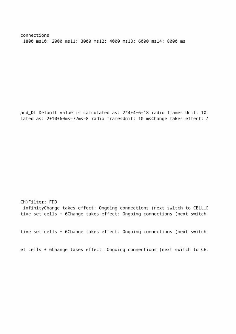
The TTI Alignment (UL and 2*DL) and UE Processing delay in number of radio frames added to the activation time (i.e. the CFN) calculated by the RNC using SRB on DCH-DL. This system constant can be calculated in the following way: cfnOffsetSrbDchDl = 2*TTI_Alignment_DL + TTI_Alignment_UL + UE_Processing_UL_and_DL Default value is calculated as: 2*4+4+6=18 radio frames Unit: 10 msChange takes effect: At next synchronized reconfiguration of the connection This attribute may only be changed by Ericsson personnel. TTI alignment and UE Processing delay in number of radio frames added to the activation time (i.e. the CFN) calculated by the RNC using SRB on HS. This system constant can be calculated in the following way: cfnOffsetSrbHs = TTI_Alignment_DL+ TTI_Alignment_UL+ UE_Processing_UL_and_DL Default value is calculated as: 2+10+60ms=72ms=8 radio framesUnit: 10 msChange takes effect: At next synchronized reconfiguration of the connection.This attribute may only be changed by Ericsson personnel.
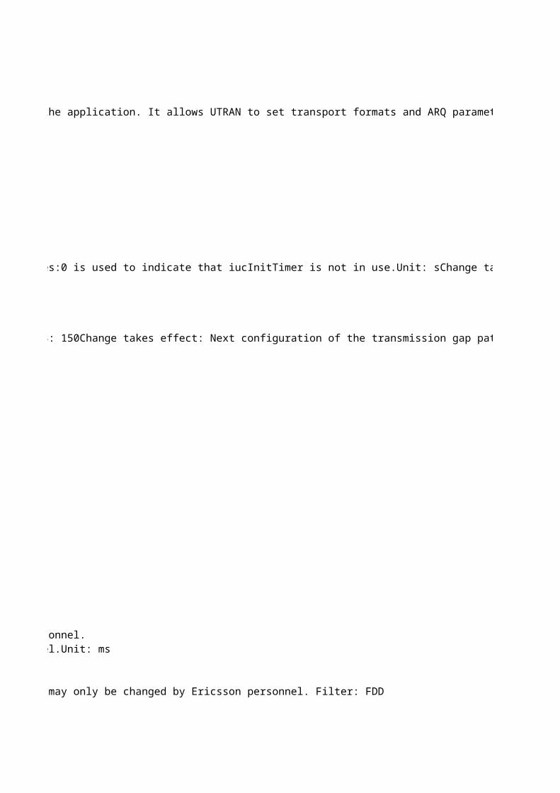
Number of pilot bits for DPCH.The number of pilot bits needs to be signaled to the UE in case the downlink physical connection uses spreading factor 128 or 256. In all other cases the UE calculates the number of pilot bits based on slot format information. The number of pilot bits is not signaled towards the RBS. For downlink physical connections using other spreading factors, the configured value will not be used by the RNC, but has to be set anyway since the parameter is defined as mandatory in the MOM. Any of the defined values will work.This attribute may only be changed by Ericsson personnel. Filter: FDD
Deprecated: This attribute is currently not used by the system. Changing it has no effect.Defines the E-DCH multiplexing option for this E-DCH radio configuration.Value mapping:0: No multiplexing except among scheduled flows.1: Multiplexing among non-scheduled flows allowed except between SRB and a non-scheduled SIP (if exists), among scheduled flows allowed, but not between scheduled and non-scheduled flows.2: All multiplexing allowed except between SRB and scheduled flows or non-scheduled SIP (if exists).3: All multiplexing allowed except between SRB and a non-scheduled SIP (if exists). This attribute may only be changed by Ericsson personnel. Minimum reduced E-DPDCH gain factor. When E-DCH is configured, if the total UE transmit power (after applying DPCCH power adjustments and gain factors) would exceed the available maximum power, the UE shall firstly reduce the E-DPDCH power with the E-DPDCH gain factor so that the total transmit power would be equal to the available maximum power. If the total transmit power is still higher than the available maximum power after applying the gain factor the E-DPDCH and the DPCCH are equally scaled to meet the available maximum power. This parameter configures the minimum factor to be used by Rel-8 UEs for reduction of the E-DPDCH gain factor. The configured value is divided by 15 to obtain the scaling factor used by the UE. -1 means that this attribute is not applicable for this instance.This attribute may only be changed by Ericsson personnel.Unit: 1 / 15 Change takes effect: Immediately
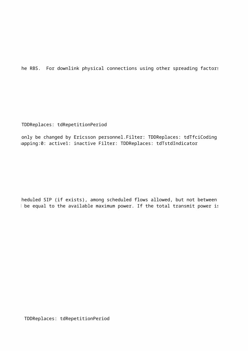
Determines the number of transmissions of a PDU before a SDU is discarded or reset procedure is initiated.The number of transmissions is equal to MaxDat - 1.RLC info on UE side UL. Valid only for RLC mode = AM.This attribute may only be changed by Ericsson personnel. Value mapping: 2: MaxDat = 3 3: 4 4: 5 5: 6 6: 7 7: 8 8: 9 9: 1010: 1511: 2012: 2513: 3014: 3515: MaxDat = 40
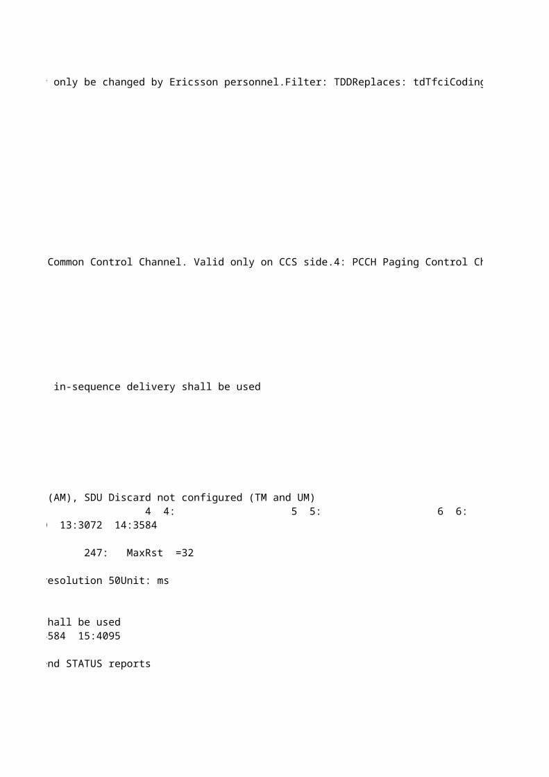
$FDD{"Array of the maximum Transport Formats (TFIs) allowed for this TrCH.The first element in the array specifies the maximum TFI for TFC Subset 0, the second element specifies the maximum TFI for TFC Subset 1, and so forth."}$TDD{"Element [0] is used as the equivalent of rateMatchingAttrDlTdd: Rate matching attribute in downlink.Element [1] is used as the equivalent of rateMatchingAttrUlTdd: Rate matching attribute in uplink.The remaining elements are not used."}The attribute must have all elements set.This attribute may only be changed by Ericsson personnel. Special values:-1: not applicable
Transmission gap length 1. Number of slots in the first transmission gap within the transmission gap pattern. This attribute may only be changed by Ericsson personnel. Value mapping:Possible values for GSM carrier RSSI Measurement are 3, 4, 5, 7, 10, 14.Possible values for Initial BSIC identification are 7, 10, 14.Possible values for BSIC re-confirmation are 7, 10, 14.Possible values for Inter Frequency measurements are 7, 10, 14.Since the value ranges are different for each pattern sequence, the system will not check the range. It is the responsibility of the user (Ericsson personnel) to check the range when configuring the parameter. Change takes effect: Next configuration of the transmission gap pattern sequence in UE, DRNC or RBS.Transmission gap length 2. Number of slots in the second transmission gap within the transmission gap pattern. This attribute may only be changed by Ericsson personnel. Dependencies:If this parameter is not explicitly set by higher layers, then tGL2 = tGL1. Value mapping:Possible values for GSM carrier RSSI Measurement are 3, 4, 5, 7, 10, 14.Possible values for Initial BSIC identification are 7, 10, 14.Possible values for BSIC re-confirmation are 7, 10, 14.Possible values for Inter Frequency measurements are 7, 10, 14.Since the value ranges are different for each pattern sequence, the system will not check the range. It is the responsibility of the user (Ericsson personnel) to check the range when configuring the parameter. Change takes effect: Next configuration of the transmission gap pattern sequence in UE, DRNC or RBS.Transmission gap pattern length 1. Number of frames in transmission gap pattern 1.This attribute may only be changed by Ericsson personnel. Special values:Initial value (set by system) for GSM carrier RSSI Measurement ("CpmTransGapPattSeq=1") is 8.Initial value (set by system) for Initial BSIC identification ("CpmTransGapPattSeq=2") is 8.Initial value (set by system) for BSIC re-confirmation ("CpmTransGapPattSeq=3") is 8.Initial value (set by system) for Inter Frequency measurements ("CpmTransGapPattSeq=4") is 4.Value mapping:Possible value for GSM carrier RSSI Measurement is 8.Possible values for Initial BSIC identification are 3, 4, 8, 12, 24.Possible values for BSIC re-confirmation are 3, 4, 8, 12, 15, 23, 24.Possible values for Inter Frequency measurements are 3, 4, 8, 12, 24, 35.Since the value ranges are different for each pattern sequence, the system will only check that the value is within the full range defined for the parameter. There is no check that a value for a specific sequence is within the range for that sequence. For example, the value 23 will be accepted for Initial BSIC identification. It is the responsibility of the user (Ericsson personnel) to check that the value for a specific sequence is within the range of that sequence when configuring the parameter. Change takes effect: Next configuration of the transmission gap pattern sequence in UE, DRNC or RBS.Transmission gap pattern length 2. Numer of frames in transmission gap pattern 2.This attribute may only be changed by Ericsson personnel. Special values:Initial value (set by system) for GSM carrier RSSI Measurement ("CpmTransGapPattSeq=1") is 8.Initial value (set by system) for Initial BSIC identification ("CpmTransGapPattSeq=2") is 8.Initial value (set by system) for BSIC re-confirmation ("CpmTransGapPattSeq=3") is 8.Initial value (set by system) for Inter Frequency measurements ("CpmTransGapPattSeq=4") is 4.Dependencies:It is up to the user (Ericsson personnel) to make sure tGLP1 = tGPL2 for subsequent changes during operation. There is no check in the code for this.Value mapping:Possible value for GSM carrier RSSI Measurement is 8.Possible values for Initial BSIC identification are 3, 4, 8, 12, 24.Possible values for BSIC re-confirmation are 3, 4, 8, 12, 15, 23, 24.Possible values for Inter Frequency measurements are 3, 4, 8, 12, 24, 35.Since the value ranges are different for each pattern sequence, the system will only check that the value is within the full range defined for the parameter. There is no check that a value for a specific sequence is within the range for that sequence. For example, the value 23 will be accepted for Initial BSIC identification. It is the responsibility of the user (Ericsson personnel) to check that the value for a specific sequence is within the range of that sequence when configuring the parameter. Change takes effect: Next configuration of the transmission gap pattern sequence in UE, DRNC or RBS.
Offset to the transmission gap connection frame number, for the pattern sequence when starting CPM.TGCFN = running CFN + startCFNoffset + TGCFNoffsetThis attribute may only be changed by Ericsson personnel. Special values:Initial value (set by system) for GSM carrier RSSI measurement ("CpmTransGapPattSeq=1") is 0.Initial value (set by system) for Initial BSIC identification ("CpmTransGapPattSeq=2") is 2.Initial value (set by system) for BSIC reconfirmation ("CpmTransGapPattSeq=3") is 6.Initial value (set by system) for Inter Frequency measurements ("CpmTransGapPattSeq=4") is 0.Change takes effect: Next configuration of the transmission gap pattern sequence in UE, DRNC or RBS.
Represents m, the modification period coefficient. The actual modification period (MP), in number of frames, equals 2^m.m >= k, where k = max[cnDrxCycleLengthPs, cnDrxCycleLengthCs, utranDrxCycleLength] To allow the UE to measure, when applicable, on another frequency when reading MCCH there has to be some gaps in the MCCH transmission (the MP shall not be fully utilized). Note: The UE and SGSN can negotiate the value of the cnDrxCycleLengthPs. This case can not be handled by the system. This attribute may only be changed by Ericsson personnel.Change takes effect: At MbmsCch lock/unlock and at system restartRepresents r, the repetition period coefficient. The number of repetitions per modification period equals 2^r while the actual repetition period, in number of frames, equals [2^m DIV 2^r], where m is the modification period coefficient.[2^m DIV 2^r] >= nrOfRrcFrames, where nrOfRrcFrames defines the number of frames the MCCH information requires in each Repetition Period. (Note: nrOfRrcFrames is not a parameter but only a definition in the above equation.)This attribute may only be changed by Ericsson personnel.Change takes effect: At MbmsCch lock/unlock and at system restartMaximum number of simultaneous ongoing MBMS sessions in one non-PL cell. The MCCH FACH with TTI 20 ms for S-CCPCH has maximum user data rate 7.6 kbps.The values of the mbmsModificationPeriodCoeff (m) and mbmsRepetitionPeriodCoeff (r) have dependencies to the number of frames that can be scheduled per Repetition Period on MCCH with the data rate 7.6 kbps. Parameters nonPlSessionsMax, plSessionsMax and neighbourCellsMax put limits on number of frames to be scheduled in a worst case scenario.It must be considered when changing any of the above parameters that the number of frames to be scheduled on MCCH for RRC messages does not exceed the number of frames that can be scheduled per Repetition Period on MCCH.This attribute may only be changed by Ericsson personnel.Change takes effect: At MbmsCch lock/unlock and at system restartFilter: FDDMaximum number of simultaneous ongoing MBMS sessions in one PL cell. The MCCH FACH with TTI 20 ms for S-CCPCH has maximum user data rate 7.6 kbps.The values of the mbmsModificationPeriodCoeff (m) and mbmsRepetitionPeriodCoeff (r) have dependencies to the number of frames that can be scheduled per Repetition Period on MCCH with the data rate 7.6 kbps. Parameters nonPlSessionsMax, plSessionsMax and neighbourCellsMax put limits on number of frames to be scheduled in a worst case scenario.It must be considered when changing any of the above parameters that the number of frames to be scheduled on MCCH for RRC messages does not exceed the number of frames that can be scheduled per Repetition Period on MCCH.This attribute may only be changed by Ericsson personnel.Change takes effect: At MbmsCch lock/unlock and at system restartMaximum number of intra-frequency neighboring cells for which information is sent on MCCH. The MCCH FACH with TTI 20 ms for S-CCPCH has maximum user data rate 7.6 kbps.The values of the mbmsModificationPeriodCoeff (m) and mbmsRepetitionPeriodCoeff (r) have dependencies to the number of frames that can be scheduled per Repetition Period on MCCH with the data rate 7.6 kbps. Parameters nonPlSessionsMax, plSessionsMax and neighbourCellsMax put limits on number of frames to be scheduled in a worst case scenario.It must be considered when changing any of the above parameters that the number of frames to be scheduled on MCCH for RRC messages does not exceed the number of frames that can be scheduled per Repetition Period on MCCH.This attribute may only be changed by Ericsson personnel.Change takes effect: At MbmsCch lock/unlock and at system restart
Maximum adjustment step for downlink power balancing.This parameter is signaled over NBAP with the values [1..10] slots, where 1 corresponds to an allowed change of the downlink power (due to downlink power balancing) of at most 1 dB every 1 slot. 10 corresponds to an allowed change of the downlink power of at most 1 dB every 10 slots.maxAdjustmentStep = 1 corresponds to a limit on rate of change of 1 dB/slot.maxAdjustmentStep = 10 corresponds to a limit on rate of change of 0.1 dB/slot.This attribute may only be changed by Ericsson personnel. Change takes effect: New connectionsFilter: FDD
The pre-allocated hardware rate for scheduled data for E-DCH users in the RBS. Needed for RBS hardware consumption calculations in RNC. The calculation is performed in the same way for 2 ms and 10 ms TTI, with this constant as input, but the values shall then be rounded up differently depending on the used TTI. This attribute may only be changed by Ericsson personnel. Dependencies: The same constant is defined in the RBS for the scheduler. These constants should be set to the same value. Unit: kbps (1000 bits per second)Resolution: 32Change takes effect: Ongoing connectionsFilter: FDD
Total size of the storage space available for PM Recording ROP files on the O&M MP.When recordingStorageSize is reached, the PM Recording function will remove the oldest recording file and continue. If the recordingStorageSize is completely used by a single recording file, the PM Recording function will stop the recording until the next ROP begins.This attribute may only be changed by Ericsson personnel. Dependencies: The file sizes for UETR and CTR recordings may never exceed the available recording storage size on the central O&M MP: recordingStorageSize >= ctrFileSize, recordingStorageSize >= uetrFileSizeUnit: kB (1000 bytes)Change takes effect: Next ROP
Time without a received CAPACITY ALLOCATION (CA) control frame, for this PQF, that results in a reduced HSDPA bit rate. The reason for checking the presence of these CAPACITY ALLOCATION control frames in RNC is that a CA shall be received at least every one second time interval (more often or once per second). If this doesn't happen, it is likely that a CA is dropped over the transport network. Further on, if several CA control frames are dropped, not received in RNC, it could mean that the best effort type of transport network is congested. This attribute may only be changed by Ericsson personnel. Special values:0 defines that CA presence supervision is turned off.Unit: 0.1 sChange takes effect: New connections
Number of pilot bits for DPCH.The number of pilot bits needs to be signaled to the UE in case the downlink physical connection uses spreading factor 128 or 256. In all other cases the UE calculates the number of pilot bits based on slot format information. The number of pilot bits is not signaled towards the RBS. For downlink physical connections using other spreading factors, the configured value will not be used by the RNC, but has to be set anyway since the parameter is defined as mandatory in the MOM. Any of the defined values will work.This attribute may only be changed by Ericsson personnel. Filter: FDD
Deprecated: This attribute is currently not used by the system. Changing it has no effect.Defines the E-DCH multiplexing option for this E-DCH radio configuration.Value mapping:0: No multiplexing except among scheduled flows.1: Multiplexing among non-scheduled flows allowed except between SRB and a non-scheduled SIP (if exists), among scheduled flows allowed, but not between scheduled and non-scheduled flows.2: All multiplexing allowed except between SRB and scheduled flows or non-scheduled SIP (if exists).3: All multiplexing allowed except between SRB and a non-scheduled SIP (if exists). This attribute may only be changed by Ericsson personnel. Minimum reduced E-DPDCH gain factor. When E-DCH is configured, if the total UE transmit power (after applying DPCCH power adjustments and gain factors) would exceed the available maximum power, the UE shall firstly reduce the E-DPDCH power with the E-DPDCH gain factor so that the total transmit power would be equal to the available maximum power. If the total transmit power is still higher than the available maximum power after applying the gain factor the E-DPDCH and the DPCCH are equally scaled to meet the available maximum power. This parameter configures the minimum factor to be used by Rel-8 UEs for reduction of the E-DPDCH gain factor. The configured value is divided by 15 to obtain the scaling factor used by the UE. -1 means that this attribute is not applicable for this instance.This attribute may only be changed by Ericsson personnel.Unit: 1 / 15 Change takes effect: Immediately
$FDD{"Array of the maximum Transport Formats (TFIs) allowed for this TrCH.The first element in the array specifies the maximum TFI for TFC Subset 0, the second element specifies the maximum TFI for TFC Subset 1, and so forth."}$TDD{"Element [0] is used as the equivalent of rateMatchingAttrDlTdd: Rate matching attribute in downlink.Element [1] is used as the equivalent of rateMatchingAttrUlTdd: Rate matching attribute in uplink.The remaining elements are not used."}The attribute must have all elements set.This attribute may only be changed by Ericsson personnel. Special values:-1: not applicable
Transmission gap length 1. Number of slots in the first transmission gap within the transmission gap pattern. This attribute may only be changed by Ericsson personnel. Value mapping:Possible values for GSM carrier RSSI Measurement are 3, 4, 5, 7, 10, 14.Possible values for Initial BSIC identification are 7, 10, 14.Possible values for BSIC re-confirmation are 7, 10, 14.Possible values for Inter Frequency measurements are 7, 10, 14.Since the value ranges are different for each pattern sequence, the system will not check the range. It is the responsibility of the user (Ericsson personnel) to check the range when configuring the parameter. Change takes effect: Next configuration of the transmission gap pattern sequence in UE, DRNC or RBS.Transmission gap length 2. Number of slots in the second transmission gap within the transmission gap pattern. This attribute may only be changed by Ericsson personnel. Dependencies:If this parameter is not explicitly set by higher layers, then tGL2 = tGL1. Value mapping:Possible values for GSM carrier RSSI Measurement are 3, 4, 5, 7, 10, 14.Possible values for Initial BSIC identification are 7, 10, 14.Possible values for BSIC re-confirmation are 7, 10, 14.Possible values for Inter Frequency measurements are 7, 10, 14.Since the value ranges are different for each pattern sequence, the system will not check the range. It is the responsibility of the user (Ericsson personnel) to check the range when configuring the parameter. Change takes effect: Next configuration of the transmission gap pattern sequence in UE, DRNC or RBS.Transmission gap pattern length 1. Number of frames in transmission gap pattern 1.This attribute may only be changed by Ericsson personnel. Special values:Initial value (set by system) for GSM carrier RSSI Measurement ("CpmTransGapPattSeq=1") is 8.Initial value (set by system) for Initial BSIC identification ("CpmTransGapPattSeq=2") is 8.Initial value (set by system) for BSIC re-confirmation ("CpmTransGapPattSeq=3") is 8.Initial value (set by system) for Inter Frequency measurements ("CpmTransGapPattSeq=4") is 4.Value mapping:Possible value for GSM carrier RSSI Measurement is 8.Possible values for Initial BSIC identification are 3, 4, 8, 12, 24.Possible values for BSIC re-confirmation are 3, 4, 8, 12, 15, 23, 24.Possible values for Inter Frequency measurements are 3, 4, 8, 12, 24, 35.Since the value ranges are different for each pattern sequence, the system will only check that the value is within the full range defined for the parameter. There is no check that a value for a specific sequence is within the range for that sequence. For example, the value 23 will be accepted for Initial BSIC identification. It is the responsibility of the user (Ericsson personnel) to check that the value for a specific sequence is within the range of that sequence when configuring the parameter. Change takes effect: Next configuration of the transmission gap pattern sequence in UE, DRNC or RBS.Transmission gap pattern length 2. Numer of frames in transmission gap pattern 2.This attribute may only be changed by Ericsson personnel. Special values:Initial value (set by system) for GSM carrier RSSI Measurement ("CpmTransGapPattSeq=1") is 8.Initial value (set by system) for Initial BSIC identification ("CpmTransGapPattSeq=2") is 8.Initial value (set by system) for BSIC re-confirmation ("CpmTransGapPattSeq=3") is 8.Initial value (set by system) for Inter Frequency measurements ("CpmTransGapPattSeq=4") is 4.Dependencies:It is up to the user (Ericsson personnel) to make sure tGLP1 = tGPL2 for subsequent changes during operation. There is no check in the code for this.Value mapping:Possible value for GSM carrier RSSI Measurement is 8.Possible values for Initial BSIC identification are 3, 4, 8, 12, 24.Possible values for BSIC re-confirmation are 3, 4, 8, 12, 15, 23, 24.Possible values for Inter Frequency measurements are 3, 4, 8, 12, 24, 35.Since the value ranges are different for each pattern sequence, the system will only check that the value is within the full range defined for the parameter. There is no check that a value for a specific sequence is within the range for that sequence. For example, the value 23 will be accepted for Initial BSIC identification. It is the responsibility of the user (Ericsson personnel) to check that the value for a specific sequence is within the range of that sequence when configuring the parameter. Change takes effect: Next configuration of the transmission gap pattern sequence in UE, DRNC or RBS.
Offset to the transmission gap connection frame number, for the pattern sequence when starting CPM.TGCFN = running CFN + startCFNoffset + TGCFNoffsetThis attribute may only be changed by Ericsson personnel. Special values:Initial value (set by system) for GSM carrier RSSI measurement ("CpmTransGapPattSeq=1") is 0.Initial value (set by system) for Initial BSIC identification ("CpmTransGapPattSeq=2") is 2.Initial value (set by system) for BSIC reconfirmation ("CpmTransGapPattSeq=3") is 6.Initial value (set by system) for Inter Frequency measurements ("CpmTransGapPattSeq=4") is 0.Change takes effect: Next configuration of the transmission gap pattern sequence in UE, DRNC or RBS.
Maximum number of simultaneous ongoing MBMS sessions in one non-PL cell. The MCCH FACH with TTI 20 ms for S-CCPCH has maximum user data rate 7.6 kbps.The values of the mbmsModificationPeriodCoeff (m) and mbmsRepetitionPeriodCoeff (r) have dependencies to the number of frames that can be scheduled per Repetition Period on MCCH with the data rate 7.6 kbps. Parameters nonPlSessionsMax, plSessionsMax and neighbourCellsMax put limits on number of frames to be scheduled in a worst case scenario.It must be considered when changing any of the above parameters that the number of frames to be scheduled on MCCH for RRC messages does not exceed the number of frames that can be scheduled per Repetition Period on MCCH.This attribute may only be changed by Ericsson personnel.Change takes effect: At MbmsCch lock/unlock and at system restartFilter: FDDMaximum number of simultaneous ongoing MBMS sessions in one PL cell. The MCCH FACH with TTI 20 ms for S-CCPCH has maximum user data rate 7.6 kbps.The values of the mbmsModificationPeriodCoeff (m) and mbmsRepetitionPeriodCoeff (r) have dependencies to the number of frames that can be scheduled per Repetition Period on MCCH with the data rate 7.6 kbps. Parameters nonPlSessionsMax, plSessionsMax and neighbourCellsMax put limits on number of frames to be scheduled in a worst case scenario.It must be considered when changing any of the above parameters that the number of frames to be scheduled on MCCH for RRC messages does not exceed the number of frames that can be scheduled per Repetition Period on MCCH.This attribute may only be changed by Ericsson personnel.Change takes effect: At MbmsCch lock/unlock and at system restartMaximum number of intra-frequency neighboring cells for which information is sent on MCCH. The MCCH FACH with TTI 20 ms for S-CCPCH has maximum user data rate 7.6 kbps.The values of the mbmsModificationPeriodCoeff (m) and mbmsRepetitionPeriodCoeff (r) have dependencies to the number of frames that can be scheduled per Repetition Period on MCCH with the data rate 7.6 kbps. Parameters nonPlSessionsMax, plSessionsMax and neighbourCellsMax put limits on number of frames to be scheduled in a worst case scenario.It must be considered when changing any of the above parameters that the number of frames to be scheduled on MCCH for RRC messages does not exceed the number of frames that can be scheduled per Repetition Period on MCCH.This attribute may only be changed by Ericsson personnel.Change takes effect: At MbmsCch lock/unlock and at system restart
Total size of the storage space available for PM Recording ROP files on the O&M MP.When recordingStorageSize is reached, the PM Recording function will remove the oldest recording file and continue. If the recordingStorageSize is completely used by a single recording file, the PM Recording function will stop the recording until the next ROP begins.This attribute may only be changed by Ericsson personnel. Dependencies: The file sizes for UETR and CTR recordings may never exceed the available recording storage size on the central O&M MP: recordingStorageSize >= ctrFileSize, recordingStorageSize >= uetrFileSizeUnit: kB (1000 bytes)Change takes effect: Next ROP
Time without a received CAPACITY ALLOCATION (CA) control frame, for this PQF, that results in a reduced HSDPA bit rate. The reason for checking the presence of these CAPACITY ALLOCATION control frames in RNC is that a CA shall be received at least every one second time interval (more often or once per second). If this doesn't happen, it is likely that a CA is dropped over the transport network. Further on, if several CA control frames are dropped, not received in RNC, it could mean that the best effort type of transport network is congested. This attribute may only be changed by Ericsson personnel. Special values:0 defines that CA presence supervision is turned off.Unit: 0.1 sChange takes effect: New connections
Minimum reduced E-DPDCH gain factor. When E-DCH is configured, if the total UE transmit power (after applying DPCCH power adjustments and gain factors) would exceed the available maximum power, the UE shall firstly reduce the E-DPDCH power with the E-DPDCH gain factor so that the total transmit power would be equal to the available maximum power. If the total transmit power is still higher than the available maximum power after applying the gain factor the E-DPDCH and the DPCCH are equally scaled to meet the available maximum power. This parameter configures the minimum factor to be used by Rel-8 UEs for reduction of the E-DPDCH gain factor. The configured value is divided by 15 to obtain the scaling factor used by the UE. -1 means that this attribute is not applicable for this instance.This attribute may only be changed by Ericsson personnel.Unit: 1 / 15 Change takes effect: Immediately
Transmission gap length 2. Number of slots in the second transmission gap within the transmission gap pattern. This attribute may only be changed by Ericsson personnel. Dependencies:If this parameter is not explicitly set by higher layers, then tGL2 = tGL1. Value mapping:Possible values for GSM carrier RSSI Measurement are 3, 4, 5, 7, 10, 14.Possible values for Initial BSIC identification are 7, 10, 14.Possible values for BSIC re-confirmation are 7, 10, 14.Possible values for Inter Frequency measurements are 7, 10, 14.Since the value ranges are different for each pattern sequence, the system will not check the range. It is the responsibility of the user (Ericsson personnel) to check the range when configuring the parameter. Change takes effect: Next configuration of the transmission gap pattern sequence in UE, DRNC or RBS.Transmission gap pattern length 1. Number of frames in transmission gap pattern 1.This attribute may only be changed by Ericsson personnel. Special values:Initial value (set by system) for GSM carrier RSSI Measurement ("CpmTransGapPattSeq=1") is 8.Initial value (set by system) for Initial BSIC identification ("CpmTransGapPattSeq=2") is 8.Initial value (set by system) for BSIC re-confirmation ("CpmTransGapPattSeq=3") is 8.Initial value (set by system) for Inter Frequency measurements ("CpmTransGapPattSeq=4") is 4.Value mapping:Possible value for GSM carrier RSSI Measurement is 8.Possible values for Initial BSIC identification are 3, 4, 8, 12, 24.Possible values for BSIC re-confirmation are 3, 4, 8, 12, 15, 23, 24.Possible values for Inter Frequency measurements are 3, 4, 8, 12, 24, 35.Since the value ranges are different for each pattern sequence, the system will only check that the value is within the full range defined for the parameter. There is no check that a value for a specific sequence is within the range for that sequence. For example, the value 23 will be accepted for Initial BSIC identification. It is the responsibility of the user (Ericsson personnel) to check that the value for a specific sequence is within the range of that sequence when configuring the parameter. Change takes effect: Next configuration of the transmission gap pattern sequence in UE, DRNC or RBS.Transmission gap pattern length 2. Numer of frames in transmission gap pattern 2.This attribute may only be changed by Ericsson personnel. Special values:Initial value (set by system) for GSM carrier RSSI Measurement ("CpmTransGapPattSeq=1") is 8.Initial value (set by system) for Initial BSIC identification ("CpmTransGapPattSeq=2") is 8.Initial value (set by system) for BSIC re-confirmation ("CpmTransGapPattSeq=3") is 8.Initial value (set by system) for Inter Frequency measurements ("CpmTransGapPattSeq=4") is 4.Dependencies:It is up to the user (Ericsson personnel) to make sure tGLP1 = tGPL2 for subsequent changes during operation. There is no check in the code for this.Value mapping:Possible value for GSM carrier RSSI Measurement is 8.Possible values for Initial BSIC identification are 3, 4, 8, 12, 24.Possible values for BSIC re-confirmation are 3, 4, 8, 12, 15, 23, 24.Possible values for Inter Frequency measurements are 3, 4, 8, 12, 24, 35.Since the value ranges are different for each pattern sequence, the system will only check that the value is within the full range defined for the parameter. There is no check that a value for a specific sequence is within the range for that sequence. For example, the value 23 will be accepted for Initial BSIC identification. It is the responsibility of the user (Ericsson personnel) to check that the value for a specific sequence is within the range of that sequence when configuring the parameter. Change takes effect: Next configuration of the transmission gap pattern sequence in UE, DRNC or RBS.
Maximum number of simultaneous ongoing MBMS sessions in one non-PL cell. The MCCH FACH with TTI 20 ms for S-CCPCH has maximum user data rate 7.6 kbps.The values of the mbmsModificationPeriodCoeff (m) and mbmsRepetitionPeriodCoeff (r) have dependencies to the number of frames that can be scheduled per Repetition Period on MCCH with the data rate 7.6 kbps. Parameters nonPlSessionsMax, plSessionsMax and neighbourCellsMax put limits on number of frames to be scheduled in a worst case scenario.It must be considered when changing any of the above parameters that the number of frames to be scheduled on MCCH for RRC messages does not exceed the number of frames that can be scheduled per Repetition Period on MCCH.This attribute may only be changed by Ericsson personnel.Change takes effect: At MbmsCch lock/unlock and at system restartFilter: FDDMaximum number of simultaneous ongoing MBMS sessions in one PL cell. The MCCH FACH with TTI 20 ms for S-CCPCH has maximum user data rate 7.6 kbps.The values of the mbmsModificationPeriodCoeff (m) and mbmsRepetitionPeriodCoeff (r) have dependencies to the number of frames that can be scheduled per Repetition Period on MCCH with the data rate 7.6 kbps. Parameters nonPlSessionsMax, plSessionsMax and neighbourCellsMax put limits on number of frames to be scheduled in a worst case scenario.It must be considered when changing any of the above parameters that the number of frames to be scheduled on MCCH for RRC messages does not exceed the number of frames that can be scheduled per Repetition Period on MCCH.This attribute may only be changed by Ericsson personnel.Change takes effect: At MbmsCch lock/unlock and at system restartMaximum number of intra-frequency neighboring cells for which information is sent on MCCH. The MCCH FACH with TTI 20 ms for S-CCPCH has maximum user data rate 7.6 kbps.The values of the mbmsModificationPeriodCoeff (m) and mbmsRepetitionPeriodCoeff (r) have dependencies to the number of frames that can be scheduled per Repetition Period on MCCH with the data rate 7.6 kbps. Parameters nonPlSessionsMax, plSessionsMax and neighbourCellsMax put limits on number of frames to be scheduled in a worst case scenario.It must be considered when changing any of the above parameters that the number of frames to be scheduled on MCCH for RRC messages does not exceed the number of frames that can be scheduled per Repetition Period on MCCH.This attribute may only be changed by Ericsson personnel.Change takes effect: At MbmsCch lock/unlock and at system restart
Minimum reduced E-DPDCH gain factor. When E-DCH is configured, if the total UE transmit power (after applying DPCCH power adjustments and gain factors) would exceed the available maximum power, the UE shall firstly reduce the E-DPDCH power with the E-DPDCH gain factor so that the total transmit power would be equal to the available maximum power. If the total transmit power is still higher than the available maximum power after applying the gain factor the E-DPDCH and the DPCCH are equally scaled to meet the available maximum power. This parameter configures the minimum factor to be used by Rel-8 UEs for reduction of the E-DPDCH gain factor. The configured value is divided by 15 to obtain the scaling factor used by the UE. -1 means that this attribute is not applicable for this instance.This attribute may only be changed by Ericsson personnel.Unit: 1 / 15 Change takes effect: Immediately

Transmission gap pattern length 1. Number of frames in transmission gap pattern 1.This attribute may only be changed by Ericsson personnel. Special values:Initial value (set by system) for GSM carrier RSSI Measurement ("CpmTransGapPattSeq=1") is 8.Initial value (set by system) for Initial BSIC identification ("CpmTransGapPattSeq=2") is 8.Initial value (set by system) for BSIC re-confirmation ("CpmTransGapPattSeq=3") is 8.Initial value (set by system) for Inter Frequency measurements ("CpmTransGapPattSeq=4") is 4.Value mapping:Possible value for GSM carrier RSSI Measurement is 8.Possible values for Initial BSIC identification are 3, 4, 8, 12, 24.Possible values for BSIC re-confirmation are 3, 4, 8, 12, 15, 23, 24.Possible values for Inter Frequency measurements are 3, 4, 8, 12, 24, 35.Since the value ranges are different for each pattern sequence, the system will only check that the value is within the full range defined for the parameter. There is no check that a value for a specific sequence is within the range for that sequence. For example, the value 23 will be accepted for Initial BSIC identification. It is the responsibility of the user (Ericsson personnel) to check that the value for a specific sequence is within the range of that sequence when configuring the parameter. Change takes effect: Next configuration of the transmission gap pattern sequence in UE, DRNC or RBS.Transmission gap pattern length 2. Numer of frames in transmission gap pattern 2.This attribute may only be changed by Ericsson personnel. Special values:Initial value (set by system) for GSM carrier RSSI Measurement ("CpmTransGapPattSeq=1") is 8.Initial value (set by system) for Initial BSIC identification ("CpmTransGapPattSeq=2") is 8.Initial value (set by system) for BSIC re-confirmation ("CpmTransGapPattSeq=3") is 8.Initial value (set by system) for Inter Frequency measurements ("CpmTransGapPattSeq=4") is 4.Dependencies:It is up to the user (Ericsson personnel) to make sure tGLP1 = tGPL2 for subsequent changes during operation. There is no check in the code for this.Value mapping:Possible value for GSM carrier RSSI Measurement is 8.Possible values for Initial BSIC identification are 3, 4, 8, 12, 24.Possible values for BSIC re-confirmation are 3, 4, 8, 12, 15, 23, 24.Possible values for Inter Frequency measurements are 3, 4, 8, 12, 24, 35.Since the value ranges are different for each pattern sequence, the system will only check that the value is within the full range defined for the parameter. There is no check that a value for a specific sequence is within the range for that sequence. For example, the value 23 will be accepted for Initial BSIC identification. It is the responsibility of the user (Ericsson personnel) to check that the value for a specific sequence is within the range of that sequence when configuring the parameter. Change takes effect: Next configuration of the transmission gap pattern sequence in UE, DRNC or RBS.
Maximum number of simultaneous ongoing MBMS sessions in one non-PL cell. The MCCH FACH with TTI 20 ms for S-CCPCH has maximum user data rate 7.6 kbps.The values of the mbmsModificationPeriodCoeff (m) and mbmsRepetitionPeriodCoeff (r) have dependencies to the number of frames that can be scheduled per Repetition Period on MCCH with the data rate 7.6 kbps. Parameters nonPlSessionsMax, plSessionsMax and neighbourCellsMax put limits on number of frames to be scheduled in a worst case scenario.It must be considered when changing any of the above parameters that the number of frames to be scheduled on MCCH for RRC messages does not exceed the number of frames that can be scheduled per Repetition Period on MCCH.This attribute may only be changed by Ericsson personnel.Change takes effect: At MbmsCch lock/unlock and at system restartFilter: FDDMaximum number of simultaneous ongoing MBMS sessions in one PL cell. The MCCH FACH with TTI 20 ms for S-CCPCH has maximum user data rate 7.6 kbps.The values of the mbmsModificationPeriodCoeff (m) and mbmsRepetitionPeriodCoeff (r) have dependencies to the number of frames that can be scheduled per Repetition Period on MCCH with the data rate 7.6 kbps. Parameters nonPlSessionsMax, plSessionsMax and neighbourCellsMax put limits on number of frames to be scheduled in a worst case scenario.It must be considered when changing any of the above parameters that the number of frames to be scheduled on MCCH for RRC messages does not exceed the number of frames that can be scheduled per Repetition Period on MCCH.This attribute may only be changed by Ericsson personnel.Change takes effect: At MbmsCch lock/unlock and at system restartMaximum number of intra-frequency neighboring cells for which information is sent on MCCH. The MCCH FACH with TTI 20 ms for S-CCPCH has maximum user data rate 7.6 kbps.The values of the mbmsModificationPeriodCoeff (m) and mbmsRepetitionPeriodCoeff (r) have dependencies to the number of frames that can be scheduled per Repetition Period on MCCH with the data rate 7.6 kbps. Parameters nonPlSessionsMax, plSessionsMax and neighbourCellsMax put limits on number of frames to be scheduled in a worst case scenario.It must be considered when changing any of the above parameters that the number of frames to be scheduled on MCCH for RRC messages does not exceed the number of frames that can be scheduled per Repetition Period on MCCH.This attribute may only be changed by Ericsson personnel.Change takes effect: At MbmsCch lock/unlock and at system restart
Minimum reduced E-DPDCH gain factor. When E-DCH is configured, if the total UE transmit power (after applying DPCCH power adjustments and gain factors) would exceed the available maximum power, the UE shall firstly reduce the E-DPDCH power with the E-DPDCH gain factor so that the total transmit power would be equal to the available maximum power. If the total transmit power is still higher than the available maximum power after applying the gain factor the E-DPDCH and the DPCCH are equally scaled to meet the available maximum power. This parameter configures the minimum factor to be used by Rel-8 UEs for reduction of the E-DPDCH gain factor. The configured value is divided by 15 to obtain the scaling factor used by the UE. -1 means that this attribute is not applicable for this instance.This attribute may only be changed by Ericsson personnel.Unit: 1 / 15 Change takes effect: Immediately
Transmission gap pattern length 1. Number of frames in transmission gap pattern 1.This attribute may only be changed by Ericsson personnel. Special values:Initial value (set by system) for GSM carrier RSSI Measurement ("CpmTransGapPattSeq=1") is 8.Initial value (set by system) for Initial BSIC identification ("CpmTransGapPattSeq=2") is 8.Initial value (set by system) for BSIC re-confirmation ("CpmTransGapPattSeq=3") is 8.Initial value (set by system) for Inter Frequency measurements ("CpmTransGapPattSeq=4") is 4.Value mapping:Possible value for GSM carrier RSSI Measurement is 8.Possible values for Initial BSIC identification are 3, 4, 8, 12, 24.Possible values for BSIC re-confirmation are 3, 4, 8, 12, 15, 23, 24.Possible values for Inter Frequency measurements are 3, 4, 8, 12, 24, 35.Since the value ranges are different for each pattern sequence, the system will only check that the value is within the full range defined for the parameter. There is no check that a value for a specific sequence is within the range for that sequence. For example, the value 23 will be accepted for Initial BSIC identification. It is the responsibility of the user (Ericsson personnel) to check that the value for a specific sequence is within the range of that sequence when configuring the parameter. Change takes effect: Next configuration of the transmission gap pattern sequence in UE, DRNC or RBS.Transmission gap pattern length 2. Numer of frames in transmission gap pattern 2.This attribute may only be changed by Ericsson personnel. Special values:Initial value (set by system) for GSM carrier RSSI Measurement ("CpmTransGapPattSeq=1") is 8.Initial value (set by system) for Initial BSIC identification ("CpmTransGapPattSeq=2") is 8.Initial value (set by system) for BSIC re-confirmation ("CpmTransGapPattSeq=3") is 8.Initial value (set by system) for Inter Frequency measurements ("CpmTransGapPattSeq=4") is 4.Dependencies:It is up to the user (Ericsson personnel) to make sure tGLP1 = tGPL2 for subsequent changes during operation. There is no check in the code for this.Value mapping:Possible value for GSM carrier RSSI Measurement is 8.Possible values for Initial BSIC identification are 3, 4, 8, 12, 24.Possible values for BSIC re-confirmation are 3, 4, 8, 12, 15, 23, 24.Possible values for Inter Frequency measurements are 3, 4, 8, 12, 24, 35.Since the value ranges are different for each pattern sequence, the system will only check that the value is within the full range defined for the parameter. There is no check that a value for a specific sequence is within the range for that sequence. For example, the value 23 will be accepted for Initial BSIC identification. It is the responsibility of the user (Ericsson personnel) to check that the value for a specific sequence is within the range of that sequence when configuring the parameter. Change takes effect: Next configuration of the transmission gap pattern sequence in UE, DRNC or RBS.
Transmission gap pattern length 1. Number of frames in transmission gap pattern 1.This attribute may only be changed by Ericsson personnel. Special values:Initial value (set by system) for GSM carrier RSSI Measurement ("CpmTransGapPattSeq=1") is 8.Initial value (set by system) for Initial BSIC identification ("CpmTransGapPattSeq=2") is 8.Initial value (set by system) for BSIC re-confirmation ("CpmTransGapPattSeq=3") is 8.Initial value (set by system) for Inter Frequency measurements ("CpmTransGapPattSeq=4") is 4.Value mapping:Possible value for GSM carrier RSSI Measurement is 8.Possible values for Initial BSIC identification are 3, 4, 8, 12, 24.Possible values for BSIC re-confirmation are 3, 4, 8, 12, 15, 23, 24.Possible values for Inter Frequency measurements are 3, 4, 8, 12, 24, 35.Since the value ranges are different for each pattern sequence, the system will only check that the value is within the full range defined for the parameter. There is no check that a value for a specific sequence is within the range for that sequence. For example, the value 23 will be accepted for Initial BSIC identification. It is the responsibility of the user (Ericsson personnel) to check that the value for a specific sequence is within the range of that sequence when configuring the parameter. Change takes effect: Next configuration of the transmission gap pattern sequence in UE, DRNC or RBS.Transmission gap pattern length 2. Numer of frames in transmission gap pattern 2.This attribute may only be changed by Ericsson personnel. Special values:Initial value (set by system) for GSM carrier RSSI Measurement ("CpmTransGapPattSeq=1") is 8.Initial value (set by system) for Initial BSIC identification ("CpmTransGapPattSeq=2") is 8.Initial value (set by system) for BSIC re-confirmation ("CpmTransGapPattSeq=3") is 8.Initial value (set by system) for Inter Frequency measurements ("CpmTransGapPattSeq=4") is 4.Dependencies:It is up to the user (Ericsson personnel) to make sure tGLP1 = tGPL2 for subsequent changes during operation. There is no check in the code for this.Value mapping:Possible value for GSM carrier RSSI Measurement is 8.Possible values for Initial BSIC identification are 3, 4, 8, 12, 24.Possible values for BSIC re-confirmation are 3, 4, 8, 12, 15, 23, 24.Possible values for Inter Frequency measurements are 3, 4, 8, 12, 24, 35.Since the value ranges are different for each pattern sequence, the system will only check that the value is within the full range defined for the parameter. There is no check that a value for a specific sequence is within the range for that sequence. For example, the value 23 will be accepted for Initial BSIC identification. It is the responsibility of the user (Ericsson personnel) to check that the value for a specific sequence is within the range of that sequence when configuring the parameter. Change takes effect: Next configuration of the transmission gap pattern sequence in UE, DRNC or RBS.

Transmission gap pattern length 1. Number of frames in transmission gap pattern 1.This attribute may only be changed by Ericsson personnel. Special values:Initial value (set by system) for GSM carrier RSSI Measurement ("CpmTransGapPattSeq=1") is 8.Initial value (set by system) for Initial BSIC identification ("CpmTransGapPattSeq=2") is 8.Initial value (set by system) for BSIC re-confirmation ("CpmTransGapPattSeq=3") is 8.Initial value (set by system) for Inter Frequency measurements ("CpmTransGapPattSeq=4") is 4.Value mapping:Possible value for GSM carrier RSSI Measurement is 8.Possible values for Initial BSIC identification are 3, 4, 8, 12, 24.Possible values for BSIC re-confirmation are 3, 4, 8, 12, 15, 23, 24.Possible values for Inter Frequency measurements are 3, 4, 8, 12, 24, 35.Since the value ranges are different for each pattern sequence, the system will only check that the value is within the full range defined for the parameter. There is no check that a value for a specific sequence is within the range for that sequence. For example, the value 23 will be accepted for Initial BSIC identification. It is the responsibility of the user (Ericsson personnel) to check that the value for a specific sequence is within the range of that sequence when configuring the parameter. Change takes effect: Next configuration of the transmission gap pattern sequence in UE, DRNC or RBS.Transmission gap pattern length 2. Numer of frames in transmission gap pattern 2.This attribute may only be changed by Ericsson personnel. Special values:Initial value (set by system) for GSM carrier RSSI Measurement ("CpmTransGapPattSeq=1") is 8.Initial value (set by system) for Initial BSIC identification ("CpmTransGapPattSeq=2") is 8.Initial value (set by system) for BSIC re-confirmation ("CpmTransGapPattSeq=3") is 8.Initial value (set by system) for Inter Frequency measurements ("CpmTransGapPattSeq=4") is 4.Dependencies:It is up to the user (Ericsson personnel) to make sure tGLP1 = tGPL2 for subsequent changes during operation. There is no check in the code for this.Value mapping:Possible value for GSM carrier RSSI Measurement is 8.Possible values for Initial BSIC identification are 3, 4, 8, 12, 24.Possible values for BSIC re-confirmation are 3, 4, 8, 12, 15, 23, 24.Possible values for Inter Frequency measurements are 3, 4, 8, 12, 24, 35.Since the value ranges are different for each pattern sequence, the system will only check that the value is within the full range defined for the parameter. There is no check that a value for a specific sequence is within the range for that sequence. For example, the value 23 will be accepted for Initial BSIC identification. It is the responsibility of the user (Ericsson personnel) to check that the value for a specific sequence is within the range of that sequence when configuring the parameter. Change takes effect: Next configuration of the transmission gap pattern sequence in UE, DRNC or RBS.
Transmission gap pattern length 1. Number of frames in transmission gap pattern 1.This attribute may only be changed by Ericsson personnel. Special values:Initial value (set by system) for GSM carrier RSSI Measurement ("CpmTransGapPattSeq=1") is 8.Initial value (set by system) for Initial BSIC identification ("CpmTransGapPattSeq=2") is 8.Initial value (set by system) for BSIC re-confirmation ("CpmTransGapPattSeq=3") is 8.Initial value (set by system) for Inter Frequency measurements ("CpmTransGapPattSeq=4") is 4.Value mapping:Possible value for GSM carrier RSSI Measurement is 8.Possible values for Initial BSIC identification are 3, 4, 8, 12, 24.Possible values for BSIC re-confirmation are 3, 4, 8, 12, 15, 23, 24.Possible values for Inter Frequency measurements are 3, 4, 8, 12, 24, 35.Since the value ranges are different for each pattern sequence, the system will only check that the value is within the full range defined for the parameter. There is no check that a value for a specific sequence is within the range for that sequence. For example, the value 23 will be accepted for Initial BSIC identification. It is the responsibility of the user (Ericsson personnel) to check that the value for a specific sequence is within the range of that sequence when configuring the parameter. Change takes effect: Next configuration of the transmission gap pattern sequence in UE, DRNC or RBS.Transmission gap pattern length 2. Numer of frames in transmission gap pattern 2.This attribute may only be changed by Ericsson personnel. Special values:Initial value (set by system) for GSM carrier RSSI Measurement ("CpmTransGapPattSeq=1") is 8.Initial value (set by system) for Initial BSIC identification ("CpmTransGapPattSeq=2") is 8.Initial value (set by system) for BSIC re-confirmation ("CpmTransGapPattSeq=3") is 8.Initial value (set by system) for Inter Frequency measurements ("CpmTransGapPattSeq=4") is 4.Dependencies:It is up to the user (Ericsson personnel) to make sure tGLP1 = tGPL2 for subsequent changes during operation. There is no check in the code for this.Value mapping:Possible value for GSM carrier RSSI Measurement is 8.Possible values for Initial BSIC identification are 3, 4, 8, 12, 24.Possible values for BSIC re-confirmation are 3, 4, 8, 12, 15, 23, 24.Possible values for Inter Frequency measurements are 3, 4, 8, 12, 24, 35.Since the value ranges are different for each pattern sequence, the system will only check that the value is within the full range defined for the parameter. There is no check that a value for a specific sequence is within the range for that sequence. For example, the value 23 will be accepted for Initial BSIC identification. It is the responsibility of the user (Ericsson personnel) to check that the value for a specific sequence is within the range of that sequence when configuring the parameter. Change takes effect: Next configuration of the transmission gap pattern sequence in UE, DRNC or RBS.

Transmission gap pattern length 1. Number of frames in transmission gap pattern 1.This attribute may only be changed by Ericsson personnel. Special values:Initial value (set by system) for GSM carrier RSSI Measurement ("CpmTransGapPattSeq=1") is 8.Initial value (set by system) for Initial BSIC identification ("CpmTransGapPattSeq=2") is 8.Initial value (set by system) for BSIC re-confirmation ("CpmTransGapPattSeq=3") is 8.Initial value (set by system) for Inter Frequency measurements ("CpmTransGapPattSeq=4") is 4.Value mapping:Possible value for GSM carrier RSSI Measurement is 8.Possible values for Initial BSIC identification are 3, 4, 8, 12, 24.Possible values for BSIC re-confirmation are 3, 4, 8, 12, 15, 23, 24.Possible values for Inter Frequency measurements are 3, 4, 8, 12, 24, 35.Since the value ranges are different for each pattern sequence, the system will only check that the value is within the full range defined for the parameter. There is no check that a value for a specific sequence is within the range for that sequence. For example, the value 23 will be accepted for Initial BSIC identification. It is the responsibility of the user (Ericsson personnel) to check that the value for a specific sequence is within the range of that sequence when configuring the parameter. Change takes effect: Next configuration of the transmission gap pattern sequence in UE, DRNC or RBS.Transmission gap pattern length 2. Numer of frames in transmission gap pattern 2.This attribute may only be changed by Ericsson personnel. Special values:Initial value (set by system) for GSM carrier RSSI Measurement ("CpmTransGapPattSeq=1") is 8.Initial value (set by system) for Initial BSIC identification ("CpmTransGapPattSeq=2") is 8.Initial value (set by system) for BSIC re-confirmation ("CpmTransGapPattSeq=3") is 8.Initial value (set by system) for Inter Frequency measurements ("CpmTransGapPattSeq=4") is 4.Dependencies:It is up to the user (Ericsson personnel) to make sure tGLP1 = tGPL2 for subsequent changes during operation. There is no check in the code for this.Value mapping:Possible value for GSM carrier RSSI Measurement is 8.Possible values for Initial BSIC identification are 3, 4, 8, 12, 24.Possible values for BSIC re-confirmation are 3, 4, 8, 12, 15, 23, 24.Possible values for Inter Frequency measurements are 3, 4, 8, 12, 24, 35.Since the value ranges are different for each pattern sequence, the system will only check that the value is within the full range defined for the parameter. There is no check that a value for a specific sequence is within the range for that sequence. For example, the value 23 will be accepted for Initial BSIC identification. It is the responsibility of the user (Ericsson personnel) to check that the value for a specific sequence is within the range of that sequence when configuring the parameter. Change takes effect: Next configuration of the transmission gap pattern sequence in UE, DRNC or RBS.

Transmission gap pattern length 2. Numer of frames in transmission gap pattern 2.This attribute may only be changed by Ericsson personnel. Special values:Initial value (set by system) for GSM carrier RSSI Measurement ("CpmTransGapPattSeq=1") is 8.Initial value (set by system) for Initial BSIC identification ("CpmTransGapPattSeq=2") is 8.Initial value (set by system) for BSIC re-confirmation ("CpmTransGapPattSeq=3") is 8.Initial value (set by system) for Inter Frequency measurements ("CpmTransGapPattSeq=4") is 4.Dependencies:It is up to the user (Ericsson personnel) to make sure tGLP1 = tGPL2 for subsequent changes during operation. There is no check in the code for this.Value mapping:Possible value for GSM carrier RSSI Measurement is 8.Possible values for Initial BSIC identification are 3, 4, 8, 12, 24.Possible values for BSIC re-confirmation are 3, 4, 8, 12, 15, 23, 24.Possible values for Inter Frequency measurements are 3, 4, 8, 12, 24, 35.Since the value ranges are different for each pattern sequence, the system will only check that the value is within the full range defined for the parameter. There is no check that a value for a specific sequence is within the range for that sequence. For example, the value 23 will be accepted for Initial BSIC identification. It is the responsibility of the user (Ericsson personnel) to check that the value for a specific sequence is within the range of that sequence when configuring the parameter. Change takes effect: Next configuration of the transmission gap pattern sequence in UE, DRNC or RBS.


![RNC-A SERIES - Bakedeco RNC-210A_Manual.pdf · RNC-90A-R/L 2 RNC-120A-R/L 2 RNC-150A-R/L 3 RNC-180A-R/L 3 RNC-210A-R/L 4 [f] WATERPROOF COVER To prevent the entrance of water, the](https://img.pdfslide.us/doc/110x75/5e680bb313a66779ab666ae1/rnc-a-series-bakedeco-rnc-210amanualpdf-rnc-90a-rl-2-rnc-120a-rl-2-rnc-150a-rl.jpg)


![UMT_IRC_INF_022089 RNC Capacity Engineering Guide UA07[1].1 Internal V03.06](https://img.pdfslide.us/doc/110x75/55cf974b550346d03390cb0f/umtircinf022089-rnc-capacity-engineering-guide-ua0711-internal-v0306.jpg)