Embed Size (px)
Citation preview

PARTSMANUALRGX5100GENERATOR
Model
PUB-GP6767Rev. 07/09

© Copyright 2009 Robin America, Inc.
Robin America, Inc.905 Telser Road • Lake Zurich, IL 60047 • Phone: 847-540-7300 • Fax: 847-438-5012e-mail: [email protected] • www.subarupower.com

RGX5100 - 3 - 07-09
HOW TO USE THIS MANUAL
Robin engines are identifi ed by MODEL, SPECIFICATION, and CODE NUMBER. For each model there may be many different versions called specifi cations. Each specifi cation will be unique in some way. The difference may only be the paint color or it may have a different type of PTO or some other signifi cant difference.In order the identify the correct service part number, it is important to confi rm the specifi ca-tion and code numbers for your engine. The specifi cation and code number together are know as the PRODUCT NUMBER.All Robin 4 cycle engines have a Product Number label similar to the label illustrated below.
The Product Number Label has a 15 digit alphanumeric string that consists of the SPECIFICATION (SPEC) number (11 digits) and the CODE number (4 digits). Please note the illustration below:
X X X X
SPEC NO. (11 digits) CODE NO. (4 digits)
PRODUCT NO. (15 digits)
E X 3 0 0
RGX5100 - 4 - 07-09
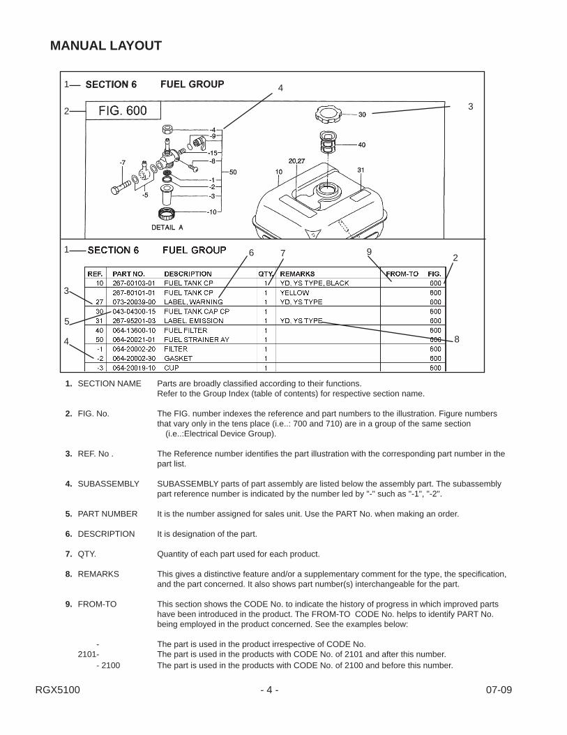
MANUAL LAYOUT
1. SECTION NAME Parts are broadly classifi ed according to their functions. Refer to the Group Index (table of contents) for respective section name.
2. FIG. No. The FIG. number indexes the reference and part numbers to the illustration. Figure numbers that vary only in the tens place (i.e..: 700 and 710) are in a group of the same section (i.e..:Electrical Device Group). 3. REF. No . The Reference number identifi es the part illustration with the corresponding part number in the part list. 4. SUBASSEMBLY SUBASSEMBLY parts of part assembly are listed below the assembly part. The subassembly part reference number is indicated by the number led by "-" such as "-1", "-2". 5. PART NUMBER It is the number assigned for sales unit. Use the PART No. when making an order.
6. DESCRIPTION It is designation of the part.
7. QTY. Quantity of each part used for each product.
8. REMARKS This gives a distinctive feature and/or a supplementary comment for the type, the specifi cation, and the part concerned. It also shows part number(s) interchangeable for the part.
9. FROM-TO This section shows the CODE No. to indicate the history of progress in which improved parts have been introduced in the product. The FROM-TO CODE No. helps to identify PART No. being employed in the product concerned. See the examples below:
- The part is used in the product irrespective of CODE No. 2101- The part is used in the products with CODE No. of 2101 and after this number. - 2100 The part is used in the products with CODE No. of 2100 and before this number.
1
2 3
4
1 6 7 9 2
8
3
5
4
RGX5100 - 5 - 07-09
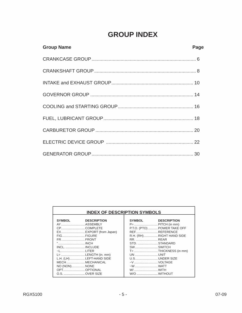
GROUP INDEXGroup Name Page
CRANKCASE GROUP ............................................................................... 6
CRANKSHAFT GROUP ............................................................................. 8
INTAKE and EXHAUST GROUP .............................................................. 10
GOVERNOR GROUP .............................................................................. 14
COOLING and STARTING GROUP ......................................................... 16
FUEL, LUBRICANT GROUP .................................................................... 18
CARBURETOR GROUP .......................................................................... 20
ELECTRIC DEVICE GROUP .................................................................. 22
GENERATOR GROUP ............................................................................. 30
SYMBOL DESCRIPTIONAY ...........................ASSEMBLYCP ...........................COMPLETEEX ...........................EXPORT (from Japan)FIG. .........................FIGUREFR. ..........................FRONT" .............................. INCHINCL. ...................... INCLUDE~L ............................LITERL= ...........................LENGTH (in. mm)L.H. (LH) .................LEFT-HAND SIDEMECH .....................MECHANICALNO (NON) ...............NONEOPT.........................OPTIONALO.S. ........................OVER SIZE
SYMBOL DESCRIPTIONP= ...........................PITCH (in mm)P.T.O. (PTO) ...........POWER TAKE OFFREF. ........................REFERENCER.H. (RH) ................RIGHT HAND SIDERR. .........................REARSTD. .......................STANDARDSW ..........................SWITCHT= ...........................THICKNESS (in mm)UN ..........................UNITU.S..........................UNDER SIZE~V ...........................VOLTAGE~W ..........................WATTW/ ...........................WITHW/O ........................WITHOUT
INDEX OF DESCRIPTION SYMBOLS

RGX5100 - 6 - 07-09
SECTION 1 CRANKCASE GROUP
FIG. 100
10
610
60 2026 70
620 680
631 630
690
710
260
250270
210
280
220 230
300
40
50
75 30
700
90 80

RGX5100 - 7 - 07-09
REF. PART NO. DESCRIPTION QTY. REMARKS FROM-TO FIG.
SECTION 1 CRANKCASE GROUP
10 291-10102-51 Crankcase Cp 1 10020 237-14202-03 Valve Guide 2 10026 277-16010-01 Stem Seal 1 10030 044-03001-60 Oil Seal 1 10040 060-03003-41 Ball Bearing 1 10050 277-15011-03 Pipe Knock 2 10060 010-50802-90 Stud 2 10070 010-50604-10 Stud 2 10075 044-00600-20 Oil Seal 1 10080 040-11400-30 Plug 1 10090 021-11400-20 Gasket 1 100210 279-11101-21 Main Bearing Cover Cp 1 100220 044-03001-60 Oil Seal 1 100230 060-03003-70 Ball Bearing 1 100250 277-45004-J1 Governor Gear Cp 1 100260 277-41901-03 Governor Sleeve 1 100270 279-63601-30 Oil Gauge Ay 2 100280 279-63601-08 Gasket 2 100300 001-04083-50 Flange Bolt 7 100610 279-13002-31 Cylinder Head Cp 1 100620 279-15001-33 Gasket, head 1 100630 011-00802-40 Flange Bolt 4 100631 011-00803-10 Flange Bolt 1 100680 277-15503-01 Rocker Cover Cp 1 100690 277-16001-13 Gasket, rocker cover 1 100700 277-15011-03 Pipe Knock 2 100710 011-00600-20 Flange Bolt 4 100960 279-99001-37 Gasket Set 1 100

RGX5100 - 8 - 07-09
FIG. 200
SECTION 2 CRANKSHAFT GROUP
310
320360
370
350
380
7010

RGX5100 - 9 - 07-09
REF. PART NO. DESCRIPTION QTY. REMARKS FROM-TO FIG.
SECTION 2 CRANKSHAFT GROUP
10 291-20701-01 Crankshaft Cp 1 20070 032-30300-10 Woodruff Key 1 200310 291-22501-00 Connecting Rod Ay 1 200320 279-23001-03 Connecting Rod Bolt 2 200350 279-23301-13 Piston Pin 1 200360 291-23401-H3 Piston 1 200370 291-23501-17 Piston Ring Set 1 200380 056-51800-10 Clip 2 200
RGX5100 - 10 - 07-09
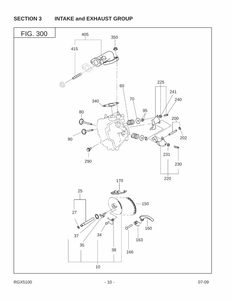
SECTION 3 INTAKE and EXHAUST GROUP
FIG. 300
415
405350
80
90
290
340
60
70
225
241
240
200
202
231
230
220
25
27
37
35
34
38
10
150
166
163
160
95
170

RGX5100 - 11 - 07-09
REF. PART NO. DESCRIPTION QTY. REMARKS FROM-TO FIG.
SECTION 3 INTAKE and EXHAUST GROUP
10 279-31602-11 Camshaft Cp 1 30025 277-35101-01 Pin Cp, camshaft 1 30027 024-00600-10 O ring 1 30034 277-38601-03 Rin, spring 1 30035 279-36401-03 Release Lever 1 30037 277-36501-03 Clip 1 30038 279-38701-13 Return Spring 1 30060 279-33601-03 Valve Spring 2 30070 269-33701-03 Spring Retainer 2 30080 279-33401-H3 Intake Valve 1 30090 279-33501-H3 Exhaust Valve 1 30095 132-10KA0-31 Collet Valve 4 300150 291-35601-01 Timing Chain Cp 1 300160 277-36911-03 Tentioner 1 300163 277-37101-03 Spring, tentioner 1 300166 277-36902-03 Pin, tentioner 1 300170 277-36913-13 Chain Guide 1 300200 277-35004-01 Pin Cp, rocker 1 300202 003-13050-00 Clip 1 300220 277-36201-00 Rocker Arm Ay, intake 1 300225 277-36202-00 Rocker Arm Ay, exhaust 1 300230 014-90500-20 Adjust Screw 1 300231 014-90500-20 Adjust Screw 1 300240 017-00500-30 Nut 1 300241 017-00500-30 Nut 1 300290 011-00600-10 Flange Bolt 1 300340 277-35201-13 Gasket, muffl er 1 300350 980-20082-80 Flange Nut 2 300405 277-34001-01 Exhaust Pipe Cp 1 300415 010-50802-90 Stud 2 300

RGX5100 - 12 - 07-09
SECTION 3 INTAKE and EXHAUST GROUP
FIG. 315
590
600
580 570
620
-220 520-250
-260
-200
510
-254

RGX5100 - 13 - 07-09
REF. PART NO. DESCRIPTION QTY. REMARKS FROM-TO FIG.
SECTION 3 INTAKE and EXHAUST GROUP
510 279-32624-20 Air Cleaner Ay 1 315-200 279-32637-28 Cleaner Body Cp 1 315-220 279-32650-18 Gasket 1 315-250 279-32646-08 Cover Cp 1 315-254 279-32683-08 Clip 4 2 315-260 073-20044-30 Label, choke 1 315520 279-32612-08 Element 1 315570 002-38060-00 Flange Nut 2 315580 011-00600-50 Flange Bolt 1 315590 056-60002-50 Clamp 1 315600 291-66001-H0 Rubber Pipe Ay 1 315620 279-39001-01 Bracket Cp, a/c 1 315

RGX5100 - 14 - 07-09
SECTION 4 GOVERNOR GROUP
FIG. 400
60
70
10 80
30
40
485310
360
370
50
20

RGX5100 - 15 - 07-09
REF. PART NO. DESCRIPTION QTY. REMARKS FROM-TO FIG.
SECTION 4 GOVERNOR GROUP
10 279-42302-60 Governor Lever Ay 1 40020 277-42201-33 Governor Shaft 1 40030 279-42702-11 Governor Rod Cp 1 40040 277-42801-23 Rod Spring 1 40050 003-13050-00 Clip 1 40060 013-00602-40 Bolt and Washer Ay 1 40070 018-60600-20 Nut 1 40080 279-42502-63 Governor Spring 1 400310 277-46501-11 Speed Control Cp 1 400360 004-31064-00 Screw 1 400370 002-17060-00 Nut 1 400485 011-00600-20 Flange Bolt 2 400

RGX5100 - 16 - 07-09
SECTION 5 COOLING and STARTING GROUP
FIG. 500
230
6282
80
25
40
220
20
10
60
61
81
-1
-5
-8
-49
-11
-6 -2-3
-4
210

RGX5100 - 17 - 07-09
REF. PART NO. DESCRIPTION QTY. REMARKS FROM-TO FIG.
SECTION 5 COOLING and STARTING GROUP
10 279-51202-01 Blower Housing Cp 1 50015 279-59604-13 Sponge 4 1 50020 073-20054-70 Label, trademark 1 50025 073-20055-70 Label, caution 1 50040 011-00600-30 Flange Bolt 4 50060 279-52711-11 Baffl e 1 Cp, case 1 Recoil Only 50061 279-52702-13 Baffl e 2, head 1 50062 277-55001-21 Duct Cp, case 1 50080 001-65081-20 Bolt 1 Recoil Only 50081 011-00600-20 Flange Bolt 1 50082 011-00600-20 Flange Bolt 3 500210 279-50301-10 Recoil Starter Ay 1 500-1 226-50716-08 Spiral Spring 1 500-2 277-50121-08 Reel 1 500-3 279-50110-08 Starter Rope 1 500-4 226-50701-08 Starter Knob 1 500-5 281-50325-08 Ratchet 1 500-6 281-50330-08 Friction Spring 1 500-8 281-50340-08 Friction Plate 1 500-11 279-50148-08 Starter Pulley 1 500-49 281-50351-08 Center Screw 1 500220 013-00602-81 Bolt and Washer Ay 4 500

RGX5100 - 18 - 07-09
SECTION 6 FUEL, LUBRICATION GROUP
FIG. 600
550 560
540

RGX5100 - 19 - 07-09
REF. PART NO. DESCRIPTION QTY. REMARKS FROM-TO FIG.
SECTION 6 FUEL, LUBRICATION GROUP
540 276-32902-J1 Insulator Cp 1 600550 279-35903-J3 Gasket 2, insulator 1 600560 279-35902-J3 Gasket 1, insulator 1 600

RGX5100 - 20 - 07-09
SECTION 6 FUEL, LUBRICATION GROUP
FIG. 640
-11
-2
-1
-103
-102
-14
-24
-18
-19
-16
-79
-28
-8-4-3
-9
-62
-5
-41
-40
-22
-15
-17
-12
210
-151-153
-154
-152
RGX5100 - 21 - 07-09
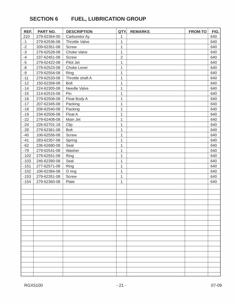
REF. PART NO. DESCRIPTION QTY. REMARKS FROM-TO FIG.
SECTION 6 FUEL, LUBRICATION GROUP
210 279-62364-00 Carburetor Ay 1 640-1 279-62536-08 Throttle Valve 1 640-2 209-62351-08 Screw 1 640-3 279-62528-08 Choke Valve 1 640-4 237-62451-08 Screw 2 640-5 279-62422-08 Pilot Jet 1 640-8 279-62523-08 Choke Lever 1 640-9 279-62554-08 Ring 1 640-11 279-62533-08 Throttle shaft A 1 640-12 150-62358-08 Bolt 1 640-14 224-62305-08 Needle Valve 1 640-15 214-62515-08 Pin 1 640-16 279-62506-08 Float Body A 1 640-17 207-62345-08 Packing 1 640-18 206-62540-08 Packing 1 640-19 234-62506-08 Float A 1 640-22 279-62408-08 Main Jet 1 640-24 226-62701-18 Clip 1 640-28 279-62361-08 Bolt 1 640-40 106-62556-08 Screw 1 640-41 283-62357-08 Spring 1 640-62 236-62680-08 Seal 1 640-79 279-62541-08 Washer 1 640-102 279-62551-08 Ring 1 640-103 246-62390-08 Seal 1 640-151 277-62571-08 Ring 1 640-152 106-62384-08 O ring 1 640-153 279-62351-08 Screw 1 640-154 279-62360-08 Plate 1 640

RGX5100 - 22 - 07-09
SECTION 7 ELECTRIC DEVICE GROUP
FIG. 700
10
15
30
11
50
100110
733
740
700
20
775
770
705
741
35
12

RGX5100 - 23 - 07-09
REF. PART NO. DESCRIPTION QTY. REMARKS FROM-TO FIG.
SECTION 7 ELECTRIC DEVICE GROUP
10 279-79230-11 Flywheel Cp 1 70010 279-79251-01 Flywheel Cp 1 15W & 40W 70011 279-79430-01 Ignition Coil Cp 1 70012 279-79301-01 Lamp Coil CP 1 12V-15W 70015 018-01800-10 Flange Nut 1 70020 267-71002-03 Ring Gear 1 Electric Start 70030 001-14062-50 Bolt and Washer Ay 2 70035 001-13062-00 Bolt and Washer Ay 2 70050 277-73102-H1 Wire 2 Cp 1 Recoil Only 70050 279-73105-H1 Wire 5 Cp Electric Start 700100 065-01401-50 Spark Plug 1 700110 065-50002-70 Spark Plug Cap 1 700700 279-76301-51 Oil Sensor Cp 1 700705 KU3-11079-01 Float C/U Cp13 1 700730 277-75801-03 Shield Plate 1 Electric Start 700733 279-75501-13 Wire Clamp 1 700740 001-14061-60 Bolt and Washer Ay 2 700741 013-00602-81 Bolt and Washer Ay 1 700775 015-20600-50 Tapping bolt 1 700

RGX5100 - 24 - 07-09
SECTION 7 ELECTRIC DEVICE GROUP
FIG. 730
-4
-19
-3
-12
-11
-17
130150
125
135
-6
-22-21
-15
-14
-2
-5
-1 -8
-7
-9
-29
-16
-18
120

RGX5100 - 25 - 07-09
REF. PART NO. DESCRIPTION QTY. REMARKS FROM-TO FIG.
SECTION 7 ELECTRIC DEVICE GROUP
120 279-70502-00 Starting Motor Ay 1 730-1 209-70550-08 Yoke Cp 1 730-2 209-70551-08 Brush 4 730-3 209-70545-08 Brush Spring 4 730-4 209-70530-08 Brush Holder 1 730-5 209-70552-08 Insulator 1 730-6 209-70554-08 Armature Ay 1 730-7 209-70521-08 Over Running Clutch 1 730-8 234-70555-08 Pinion Stopper 1 730-9 279-70550-08 Housing Cp 1 730-11 209-70505-18 Frame Cp 1 730-12 209-70510-08 Bush 1 730-14 209-70525-08 Lever 1 730-15 279-70515-18 Magnet Switch Cp 1 730-16 209-70557-18 Snap Ring 1 730-17 209-70558-08 Through Bolt 2 730-18 949-29970-02 Nut 2 730-19 209-70560-08 Nut 1 730-21 107-70652-08 Spring Washer 1 730-22 211-70584-08 Nut 1 730-29 209-70511-08 Bush 1 730125 279-76511-11 Bracket Cp, sel 1 730130 214-79007-01 Bolt, starter 2 730135 011-00600-20 Flange Bolt 3 730150 003-10080-00 Washer 2 730
RGX5100 - 26 - 07-09
SECTION 7 ELECTRIC DEVICE GROUP
FIG. 740
610
630
600 640
740
RGX5100 - 27 - 07-09
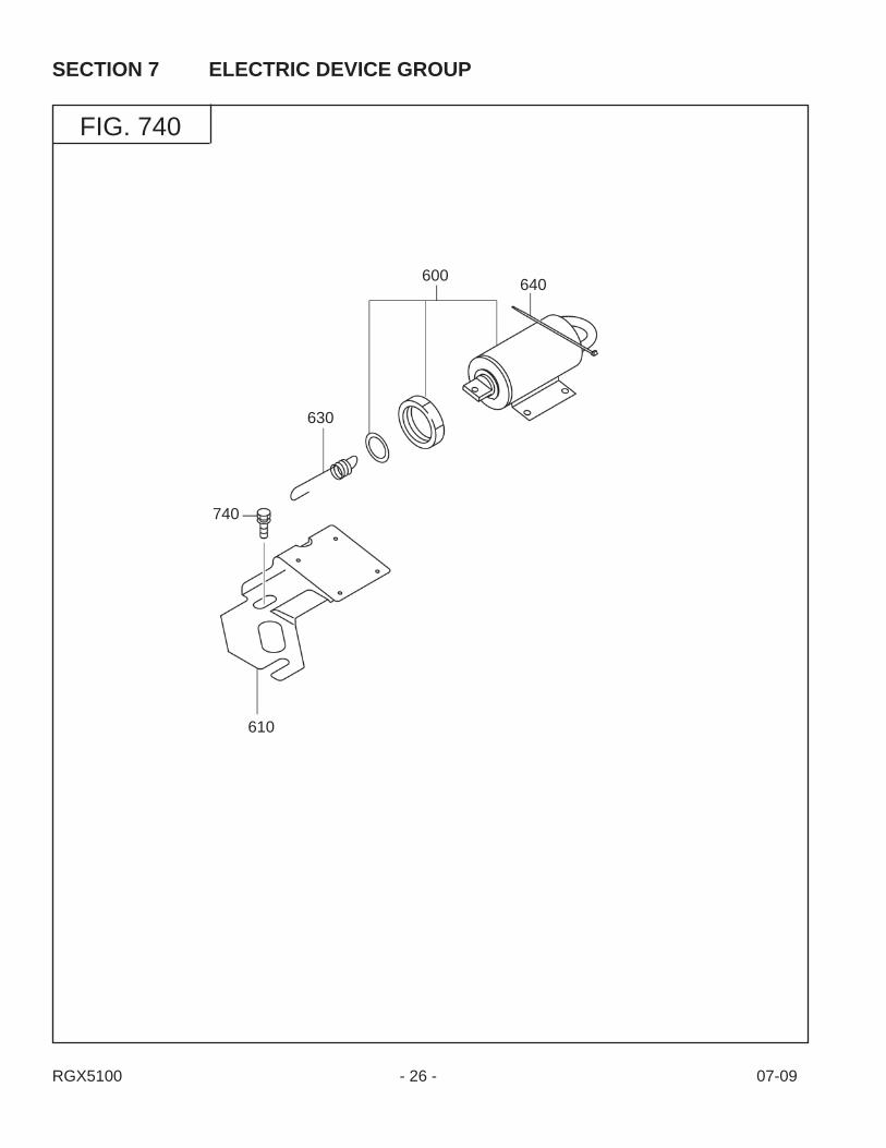
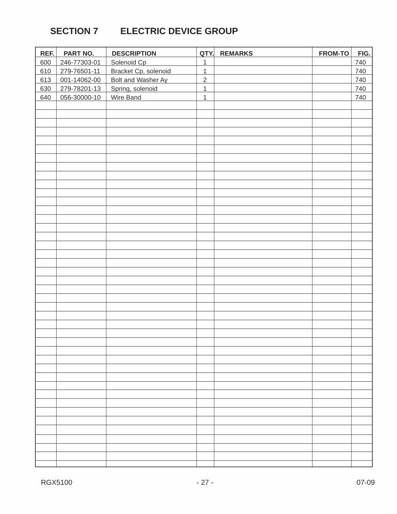
REF. PART NO. DESCRIPTION QTY. REMARKS FROM-TO FIG.
SECTION 7 ELECTRIC DEVICE GROUP
600 246-77303-01 Solenoid Cp 1 740610 279-76501-11 Bracket Cp, solenoid 1 740613 001-14062-00 Bolt and Washer Ay 2 740630 279-78201-13 Spring, solenoid 1 740640 056-30000-10 Wire Band 1 740

RGX5100 - 28 - 07-09
SECTION 21 ENGINE GROUP
FIG. 2130

RGX5100 - 29 - 07-09
REF. PART NO. DESCRIPTION QTY. REMARKS FROM-TO FIG.
SECTION 21 ENGINE GROUP
1 279-30502-01 Muffl er Cp 1 21302 31C-14001-01 Spark Arrestor p 1 21303 015-00400-10 Tapping Screw 4 21304 279-34702-01 Muffl er Cover Cp 1 21305 279-39101-11 Muffl er Bracket Cp 1 21306 011-00600-10 Flange Bolt 4 21307 001-14082-00 Bolt and Washer Ay 2 21308 001-14081-60 Bolt and Washer Ay 1 21309 277-35201-01 Gasket Cp, exhaust 1 213010 980-20082-80 Flange Nut 2 2130

RGX5100 - 30 - 07-09
SECTION 22 GENERATOR GROUP
FIG. 2200

RGX5100 - 31 - 07-09
REF. PART NO. DESCRIPTION QTY. REMARKS FROM-TO FIG.
SECTION 22 GENERATOR GROUP
1 36C-20002-08 Stator Cp 1 22002 36C-20101-08 Rotor Cp 1 22003 36C-20202-08 AVR Cp 1 22004 36A-20300-08 Brush Cp 1 22005 36A-22000-08 Gen Bracket 1 1 22006 36A-22100-08 Gen Bracket N 1 22007 36C-22200-08 Gen Bracket 2 1 22008 36C-23000-08 Bracket Cover 1 22009 36A-25000-08 Bushing 1 220010 36B-21000-08 Stator Bolt 4 220011 36A-80005-08 Flange Bolt 4 220012 36A-80001-08 Flange Bolt 2 220013 36A-80100-08 Screw and Washer Ay 1 220014 36A-80002-08 Flange Bolt 4 220015 36A-25001-08 Diode Cp 1 220016 36A-80101-08 Screw and Washer Ay 1 220017 36C-25002-08 Tube 1 220018 36A-25003-08 Grommet 1 220019 36A-70000-08 Connector 1 6 p 220020 36A-70004-08 Connector 1 4 p 220021 36A-70002-08 Connector 1 2 p 220022 36A-70101-08 Retainer 3 2 p 220023 36A-70100-08 Retainer 2 3 p 220024 36A-71013-08 Wire 1 green 220025 36A-71001-08 Wire 1 white 220026 36A-80200-08 Screw 4 220027 36C-21100-08 Rotor Bolt 1 220028 36C-25004-08 Sponge, fi lter 1 2200
RGX5100 - 32 - 07-09
SECTION 23 BASE, FRAME GROUP
FIG. 2300

RGX5100 - 33 - 07-09
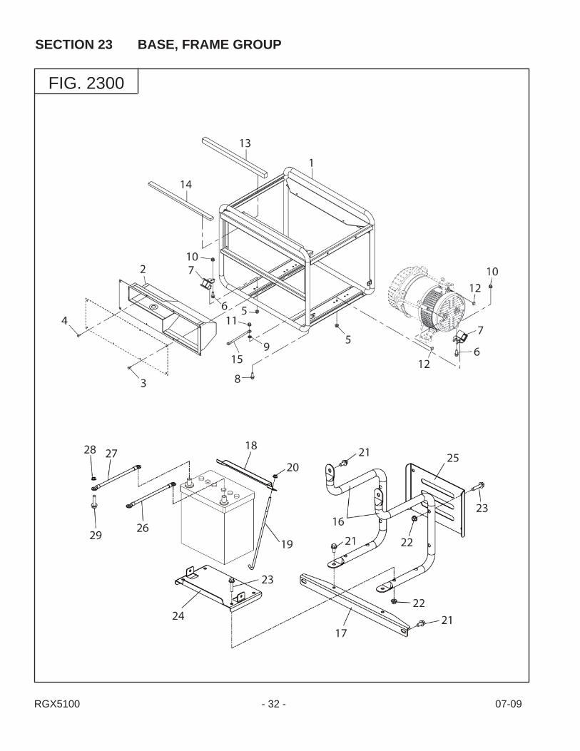
REF. PART NO. DESCRIPTION QTY. REMARKS FROM-TO FIG.
SECTION 23 BASE, FRAME GROUP
1 36C-30001-08 Pipe Frame Cp 1 23002 36C-40001-08 Control Box Cp 1 23003 36A-80104-08 Screw and Washer Ay 4 23004 36A-80105-08 Screw and Washer Ay 4 23005 36A-81002-08 Flange Nut 4 23006 36A-80006-08 Flange Bolt 4 23007 36C-31000-08 Mount Cp 4 23008 36A-80004-08 Flange Bolt 1 23009 36A-82001-08 Lock Washer 1 230010 36A-81003-08 Flange Nut 4 230011 36A-81004-08 Flange Nut 1 230012 36A-25005-08 Sponge, gen 2 230013 36A-35000-08 Sponge, tank 1 230014 36C-35001-08 Sponge, panel 1 230015 36A-71019-08 Wire 1 green/yellow 230016 36C-39001-08 Battery Frame 1 Cp 2 Electric Start 230017 36C-39002-08 Battery Frame 2 Cp 1 Electric Start 230018 36C-39003-08 Setting Plate Cp 1 Electric Start 230019 36C-39004-08 Setting Bolt 2 Electric Start 230020 36A-81004-08 Flange Nut 1 Electric Start 230021 36A-80009-08 Flange Bolt 6 Electric Start 230022 36A-81006-08 Flange Nut 8 Electric Start 230023 36A-80010-08 Flange Bolt 8 Electric Start 230024 36C-39005-08 Battery Plate Cp 1 Electric Start 230025 36C-39006-08 Protection Plate 1 Electric Start 230026 36C-39007-08 Starter Cable 1 Electric Start 230027 36C-39008-08 Earth Cable 1 Electric Start 230028 36A-81003-08 Flange Nut 1 Electric Start 230029 36A-80006-08 Flange Bolt 1 Electric Start 2300

RGX5100 - 34 - 07-09
SECTION 24 CONTROL GROUP - RECOIL
FIG.2400

SECTION 24 CONTROL GROUP - RECOIL
RGX3800 - 35 - 07-09
REF. PART NO. DESCRIPTION QTY. REMARKS FROM-TO FIG. 1 36C-41002-08 Control Panel Cp 1 24002 36A-49000-08 Switch, engine 1 24003 36A-47002-08 AC Concent 2 GFCI 24004 36B-47000-08 AC Concent 1 L5-30 24005 36B-47001-08 AC Concent 1 L14-30 24006 36C-48001-08 Circuit Breaker 1 20A 24007 36A-49003-08 Pilot Lamp 1 24008 36A-49002-08 Hour Meter 1 24009 36A-47101-08 DC Concent 1 240010 36A-48001-08 Circuit Breaker 1 10A 240011 36B-49000-08 Switch, v select 1 240012 36B-49001-08 Switch, i/c 1 240013 36A-80102-08 Screw and Washer Ay 1 240014 36A-82000-08 Lock Washer 1 240015 36A-81000-08 Flange Nut 1 240016 36A-82100-08 Cap Washer 1 240017 36A-82200-08 Washer 1 240018 36A-82300-08 Spring Washer 1 240019 36A-81100-08 Wing Nut 1 240020 36A-70003-08 Connector 1 2 p 240021 36A-70001-08 Connector 1 6 p 240022 36A-70101-08 Retainer 3 2 p 240023 36A-70100-08 Retainer 2 3 p 240024 36A-80202-08 Screw 10 240025 36A-81001-08 Flange Nut 10 240026 36A-80103-08 Screw and Washer Ay 4 240027 36A-81005-08 Flange Nut 2 240028 36A-80203-08 Screw 2 240029 36A-70300-08 Terminal 1 240030 36A-70007-08 Connector 1 4 p 240031 36C-49900-08 Grommet 1 240032 KU3-11015-01 Idle C/U Cp 1 150V 240033 36A-80204-08 Screw 2 240034 36A-71003-08 Wire 1 white 240035 36A-71006-08 Wire 1 black 240036 36A-71036-08 Wire 1 green 240037 36A-71037-08 Wire 1 green 240038 36A-71029-08 Wire 2 orange 240039 36A-71038-08 Wire 1 red 240040 36A-71039-08 Wire 1 red 240041 36A-71040-08 Wire 1 red 240042 36A-71041-08 Wire 1 orange 240043 36A-71042-08 Wire 1 blue 240044 36A-71043-08 Wire 1 blue 240045 36A-71044-08 Wire 1 blue 240046 36A-71045-08 Wire 1 gray 2400

RGX5100 - 36 - 07-09
SECTION 24 CONTROL GROUP - RECOIL
FIG.2400

SECTION 24 CONTROL GROUP - RECOIL
RGX3800 - 37 - 07-09
REF. PART NO. DESCRIPTION QTY. REMARKS FROM-TO FIG. 47 36A-71046-08 Wire 1 blue 240048 36A-71047-08 Wire 1 red 240049 36A-71048-08 Wire 1 white 240050 36A-70006-08 Connector Ay 1 2400
RGX5100 - 38 - 07-09
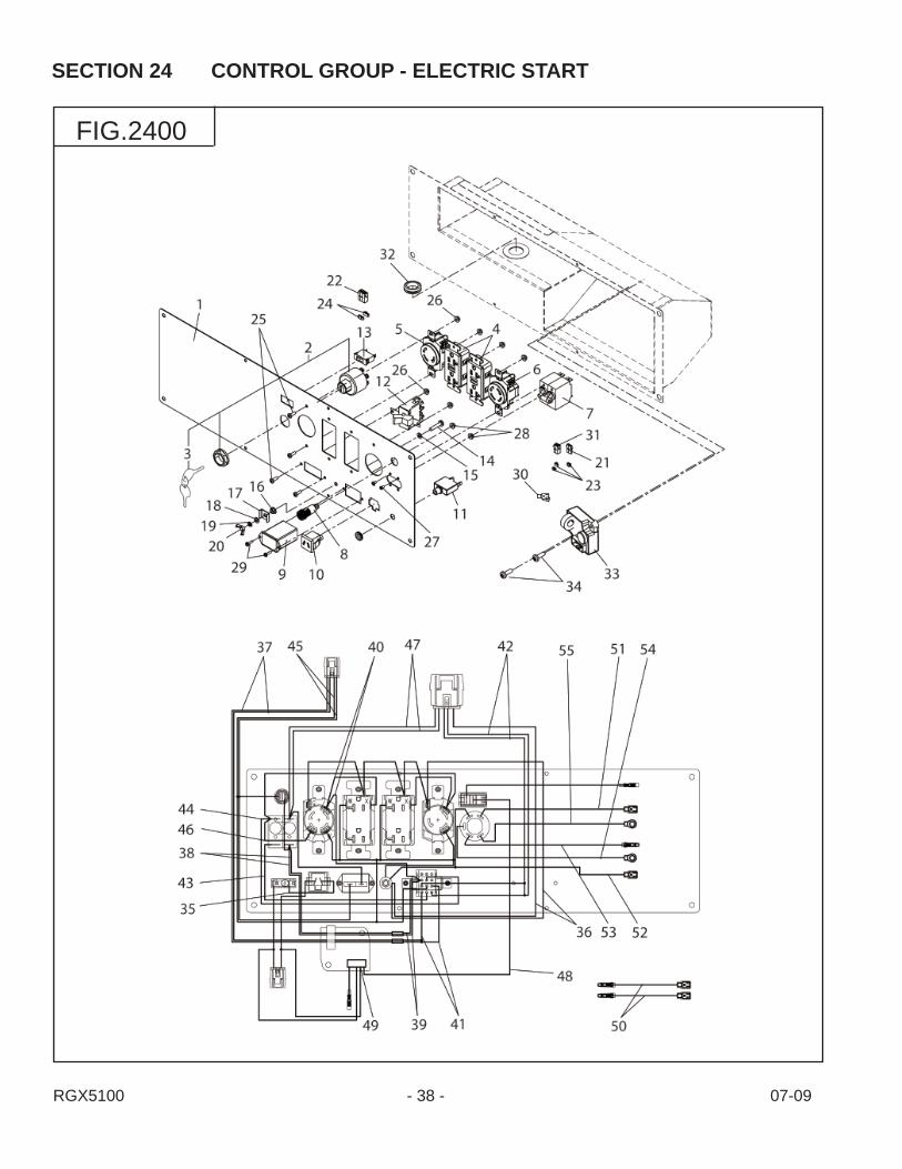
SECTION 24 CONTROL GROUP - ELECTRIC START
FIG.2400

SECTION 24 CONTROL GROUP - ELECTRIC START
RGX3800 - 39 - 07-09
REF. PART NO. DESCRIPTION QTY. REMARKS FROM-TO FIG. 1 36C-41003-08 Control Panel Cp 1 24002 066-00003-30 Switch, engine 1 24003 066-00099-80 Key, switch 2 24004 36A-47002-08 AC Concent 2 GFCI 24005 36B-47000-08 AC Concent 1 3 p 24006 36B-47001-08 AC Concent 1 4 p 24007 36C-48001-08 Circuit Breaker 1 20A 24008 36A-49003-08 Pilot Lamp 1 24009 36A-49002-08 Hour Meter 1 240010 36A-47101-08 DC Concent 1 240011 36A-48001-08 Circuit Breaker 1 10A 240012 36B-49000-08 Switch, v select 1 240013 36B-49001-08 Switch, i/c 1 240014 36A-80102-08 Screw and Washer Ay 1 240015 36A-82000-08 Lock Washer 1 240016 36A-81000-08 Flange Nut 1 240017 36A-82100-08 Cap Washer 1 240018 36A-82200-08 Washer 1 240019 36A-82300-08 Spring Washer 1 240020 36A-81100-08 Wing Nut 1 240021 36A-70003-08 Connector 1 2 p 240022 36A-70001-08 Connector 1 6 p 240023 36A-70101-08 Retainer 3 2 p 240024 36A-70100-08 Retainer 2 3 p 240025 36A-80202-08 Screw 10 240026 36A-81001-08 Flange Nut 10 240027 36A-80103-08 Screw and Washer Ay 4 240028 36A-81005-08 Flange Nut 2 240029 36A-80203-08 Screw 2 240030 36A-70300-08 Terminal 1 240031 36A-70007-08 Connector 1 4 p 240032 36C-49900-08 Grommet 1 240033 KU3-11015-01 Idle C/U Cp 1 150V 240034 36A-80204-08 Screw 2 240035 36A-71003-08 Wire 1 white 240036 36A-71037-08 Wire 1 green 240037 36A-71029-08 Wire 2 orange 240038 36A-71038-08 Wire 1 red 240039 36A-71039-08 Wire 1 red 240040 36A-71040-08 Wire 1 red 240041 36A-71041-08 Wire 1 orange 240042 36A-71042-08 Wire 1 blue 240043 36A-71043-08 Wire 1 blue 240044 36A-71044-08 Wire 1 blue 240045 36A-71045-08 Wire 1 gray 240046 36A-71046-08 Wire 1 blue 2400

RGX5100 - 40 - 07-09
SECTION 24 CONTROL GROUP - ELECTRIC START
FIG.2400
SECTION 24 CONTROL GROUP - ELECTRIC START
RGX3800 - 41 - 07-09
REF. PART NO. DESCRIPTION QTY. REMARKS FROM-TO FIG. 47 36A-71047-08 Wire 1 red 240048 36A-71048-08 Wire 1 white 240049 36A-70006-08 Connector 1 240050 36A-71049-08 Wire 2 blue 240051 36A-71050-08 Wire 1 gray 240052 36A-71051-08 Wire 1 green 240053 36A-71052-08 Wire 1 black 240054 36A-71053-08 Wire 1 red 240055 36A-71054-08 Wire 1 orange 2400

RGX5100 - 42 - 07-09
SECTION 26 FUEL TANK GROUP
FIG.2600
RGX5100 - 43 - 07-09
REF. PART NO. DESCRIPTION QTY. REMARKS FROM-TO FIG.
SECTION 26 FUEL TANK GROUP
1 36C-36001-01 Fuel Tank Cp 1 26002 043-05900-11 Fuel Tank Cap Ay 1 26003 064-15400-11 Fuel Filter 1 26004 064-80003-00 Fuel Gauge Cp 1 26005 014-50500-40 Screw, counterhead 2 26006 011-00602-20 Flange Bolt, tank 4 26007 391-39000-13 Rubber, tank 4 26008 064-20100-01 Fuel Strainer Ay 1 26009 064-20041-10 Filter 1 260010 064-20014-30 Rubber Packing 1 260011 064-20014-10 Cup 1 260012 064-20100-30 Lock Nut 1 260013 064-20003-30 O Ring 2 260014 064-20027-90 Bolt 1 260015 064-20032-30 Spring 1 260016 270-62603-11 Fuel Pipe Cp 1 260017 X56-11100-60 Hose Clamp 2 2600

RGX5100 - 44 - 07-09
SECTION 29 ACCESSORY GROUP
FIG.2900

RGX5100 - 45 - 07-09
REF. PART NO. DESCRIPTION QTY. REMARKS FROM-TO FIG.
SECTION 29 ACCESSORY GROUP
1 277-90301-H0 Accessory Tool Kit 1 29002 36A-79000-08 Battery Cable 1 29003 36A-98001-08 Label, fuel cock 1 29004 36A-98002-08 Label, symbol-tank 1 29005 36A-98003-08 Label, hot & gas 1 29006 36C-90003-08 Label, trademark 1 29007 36C-91003-08 Label, specifi cation 1 29008 36A-98005-08 Label, co gas 1 29009 36A-78000-08 AC Plug 1 L14 30P 290010 36A-78001-08 AC Plug 1 L5 30P 2900

PRINTED IN THE USA