Embed Size (px)
Citation preview
ECD-KEB F5 VF INSTALLATION MANUAL ______________________________________________________________________________________________________________________________________________
Revision Date June 9, 2016
ECD System
Manual
Volume
1
Table of Contents
Table of Contents .................................... 1
Section 1. INTRODUCTION & SAFETY REGULATIONS ..................... 2
Section 1.1 Safety Regulations ............... 2
Section 1.2 Obligations & Liability ......... 2
1.2.1 Following operating instructions. ......................................... 2
1.2.2 Obligations of operator. ............ 3
1.2.3 Obligations of personnel. .......... 3
1.2.4 Hazards associated with the equipment. ........................................... 3
1.2.5 Warranty and liability. ............. 3
1.2.6 Organisational measures. ......... 4
1.2.7 Protective equipment. ............... 4
1.2.8 Informal safety measures. ........ 4
1.2.9 Training of personnel. .............. 4
1.2.10 Machine controls. .................... 4
1.2.11 Safety during normal operation. ............................................. 5
1.2.12 Hazards caused by electric power. ................................................... 5
1.2.13 VF Drive electrical hazards. ... 5
1.2.14 Special danger areas. (examples). ........................................... 5
Section 2. CONTROLLER INSTALLATION .................................... 6
2.1.1 General ........................................ 6
2.1.2 Heat Dissipation ......................... 6
2.2 Controller Ancillaries ........................ 6
2.2.1 Braking Resistor ........................ 6
2.2.2 Hoist Motor ................................ 7
2.2.3 Encoder – Closed Loop Operation ............................................. 7
2.2.4 SIS Shaft Information System .. 8
2.2.5 Limits .......................................... 8
2.2.6 Brake........................................... 8
2.2.7 Door Motors ............................... 8
Section 3. PREPARING TO RUN. ........ 9
3.1.1 Controller Preparation.............. 9
3.1.2 Controller Activation ................ 9
3.2.1 VF Drive Programming .......... 10
3.2.2 VF Drive Parameters............... 10
3.2.3 Entering Parameters ............... 12
3.2.4 Controller Inspection Operation ............................................................ 14
Section 4. Full Speed Running ............ 15
4.1 Confirmations ............................. 15
4.2 SIS Sequence Confirmation ....... 15
4.2.1 Correction Run ........................ 16
4.2.2 Ride Quality ............................ 16
4.2.3 Floor Levels .......................... 16
4.2.4 Emergency Terminal Slowdown ............................................................ 16
Section 5. Combivis Software ............... 17
5.1 Installation and Setup Combivis
5 17
5.1.1 Software Install ..................... 17
5.1.2 Communication Faults ......... 17
5.1.3 Language Selection ............... 19
5.2 Common Commands .............. 21
Online Commands ............................. 21
5.2.1 Changing Parameters ........... 21
5.2.2 Upload parameter list from inverter ........................................... 23
5.2.3 Download a parameter list to a drive ................................................ 23
5.2.3 To reload the default drive settings to F4 contact ECD ........... 23
5.2.4 Oscilloscope Functions ......... 23
Offline Commands ............................. 27
5.2.5 To view a saved Parameter List .................................................. 27
5.2.6 To View a saved Scope Trace ......................................................... 27
5.3 Installation and Setup Combivis
6 28

I N T R O D U C T I O N & S A F E T Y R E G U L A T I O N S
2
Section 1. INTRODUCTION & SAFETY REGULATIONS
ECD-KEBVF Elevator Controller Installation
and Adjustment Manual
This manual provides a guide for the installation and adjustment of the ECD / KEB VF controller package up to the inspection run stage . This manual is to be used in conjunction with the Keb F5 lift technology instruction manual and the ECD 100-173/4 controller manuals. Please take the time to read these manuals carefully. They have been provided to help you obtain an overall understanding of the operation of the controller.
The KEB Combivert F5 Variable Frequency Drive is for stepless open loop/closed loop control of three phase asynchronous elevator hoist motors. The VF Drive receives inputs from the ECD controller. Shaft position of the elevator is supplied via the SIS, Shaft Information System. For closed loop operation the speed feedback is supplied via an encoder attached to the hoist motor.
Section 1.1 Safety Regulations
• Installation of this equipment shall be done in accordance with all applicable local codes and NFPA 70 (National Electric Code) for the U.S.A. and C22.1-02 Canadian Electrical Code Part 1 for Canada as well as ASME A17.1,ASME A17.5 – 1996 / CAN/CSA-B44.1-96.
• Elevator controllers and other electrical components can cause serious harm or death if installation guides are not met. It is the responsibility of the installer of our equipment to ensure that once installed, the equipment does not pose any threat, danger or hazard.
Section 1.2 Obligations & Liability
1.2.1 Following operating instructions.
• In order to ensure safe handling and problem free operation of this equipment, it is absolutely essential for the relevant personal to be fully acquainted with the relevant safety regulations.
Section
1
I N T R O D U C T I O N & S A F E T Y R E G U L A T I O N S
3
• These operating instructions contain the most important information for operating the machine correctly and safely.
• These operating instructions, in particular the safety regulations, must be observed by all those persons who work on the equipment.
• Furthermore, all locally applicable rules and regulations relating to accident prevention and installation must be observed.
1.2.2 Obligations of operator.
The operator undertakes to allow only those persons to work on the equipment who
• Are fully acquainted with the basic regulations relating to safety in the workplace and accident prevention and to have been trained in handling the equipment.
• Have read the safety regulations and the warning notices contained in these the operating instructions and have confirmed by way of their signature that they have fully understood these; a form for this is found in the appendix.
• Regular checks are conducted to ensure that personnel perform their duties with safety considerations foremost in their minds.
1.2.3 Obligations of personnel.
All personnel charged with working on the machine undertake prior to starting work to
• Observe the basic regulations relating to safety in the workplace and accident prevention.
• Read the operating instructions, in particular the safety regulations, and confirm by way of their signature that they have understood them.
1.2.4 Hazards associated with the equipment.
The equipment is built with state-of-the-art technology and recognized safety regulations. Nevertheless, use of the equipment can result in dangers to life and limb for the installer, user or a third party and in impairments to the equipment or to other material property. The equipment must only be used
• For its intended purpose.
• In perfect condition in terms of safety requirements.
Operate the equipment in technically perfect condition and for its intended use only while bearing in mind all safety and hazard considerations and following the operating instructions. In particular, faults which restrict safety must be rectified immediately after they have been identified and at the latest before the equipment is started up.
1.2.5 Warranty and liability.
Our “Sales terms and conditions” apply. These terms and conditions will have been available to the purchaser at time of sale. Warranty and liability shall be limited to repairs and replacement to the equipment purchased from us. Warranty and liability claims shall not be entertained if they can be traced back to one or more of the following causes.
• Equipment not used for its intended purpose.
• Improper installation, startup, operation and maintenance of the equipment.
WARNING This is a Class A product. In a domestic environment this product may cause radio interference in which case the user may be required to take adequate measures.
I N T R O D U C T I O N & S A F E T Y R E G U L A T I O N S
4
• Operation of the equipment with faulty safety devices or improperly installed or non-operational safety and protective equipment.
• Failure to observe the information, instructions and notices contained in the operating instructions relating to transportation, storage, installation, startup, operation, maintenance and setting up of the equipment.
• Inadequate monitoring of the equipment parts which are subject to wear.
• Improperly conducted repairs.
• Catastrophes caused by the influence of foreign bodies and force majeure.
1.2.6 Organisational measures.
• The installer and or maintainer shall provide the necessary protective equipment for the personnel
• All existing safety equipment must be checked at regular intervals.
1.2.7 Protective equipment.
• At all times, prior to putting the machine into operation, all protective equipment must be correctly installed and in proper working condition.
• Protective equipment may only be removed
- after the machine has come to a complete stop and the machine has been disabled to ensure it cannot be started up again.
- if subcomponents are delivered, the operator must install the protective equipment in accordance with regulations
1.2.8 Informal safety measures.
• Keep the operating instructions and circuit diagrams permanently at the site where the equipment is installed.
• In addition to the operating instructions, the generally valid and local regulations relating to accident prevention and environmental protection must be provided and observed.
• Maintain all safety and danger notices on/next to the machine in legible condition and comply with them.
• If the equipment is sold or transferred, the operating instructions must be included with the equipment.
1.2.9 Training of personnel.
• Only personnel who have been trained and instructed are allowed to work on the machine.
• The responsibilities of the personnel must be clearly defined for the machine/controller installation, startup, operation, setting-up, maintenance and repairs.
• Personnel still in the process of being trained are only permitted to work at the machine under the supervision of an experienced person.
1.2.10 Machine controls.
• Under no circumstances carry out any program modifications to the software!
• Only properly instructed personnel are permitted to operate the controls.
• The machine must not be operated if potential electromagnetic interference sources are acting on the machine. Interference sources are e.g. welding equipment, portable phones.
I N T R O D U C T I O N & S A F E T Y R E G U L A T I O N S
5
1.2.11 Safety during normal operation.
• Only operate the machine when all protective equipment is fully operational.
• Prior to switching on the machine, ensure that the startup can cause no harm to personnel.
• Regularly maintain and check machine for externally identifiable damage and check that all the safety devices are operational.
1.2.12 Hazards caused by electric power.
• Work on the electric power supply may only be carried out by a qualified electrician.
• Check the electrical equipment of the machine at regular intervals. Repair loose connections and scorched cables immediately.
• Keep the control cabinet locked at all times. Access is only permitted to authorised personnel with a key or tool.
• If work has to be carried out on live parts, do this only in the presence of a second person who can switch off the master switch in an emergency.
• The machine causes electromagnetic interference sources. For this reason, do not use any sensitive equipment in its vicinity.
• For EMC reasons, the controller must not be modified.
1.2.13 VF Drive electrical hazards.
• WARNING! VF Drive capacitors remain charged with high voltage for a short period of time once power has been removed. Do not work on VF Drive for 5 minutes after power has been removed.
1.2.14 Special danger areas. (examples).
• When on inspection, always ensure either of the control buttons stop the lift. The common must break the safety line.
• Never place yourself or any party in a position of danger where relying on any single safety measure.
• Always treat terminals and conductors as dangerous. High voltages may also be superimposed on 0v and 24VDC lines where no reference to ground exists. Always meter these points to ensure correct voltage exists.
• Automatic machines start without warning. Care must be taken at all times.
• All internal components of the controller must be protected against contamination from dirt, dust, metal filings etc resulting from the mounting process and general operation.
C O N T R O L L E R I N S T A L L A T I O N
6
Section 2. CONTROLLER INSTALLATION 2.1.1 General
Before disconnecting old controller we highly recommend that the actual lift speed, motor RPM and gearbox ratio be measured and recorded as the data plates are not always accurate. Nb: Use a hand held tacho for accurate speed measurement. Controller cabinet must be installed in a location free from;
• Dust and dirt.
• Excessive heat and humidity. Ambient temperature should not exceed 40°C /104°F.
• Excessive vibrations.
• Mist or water When mounting controller cabinet, ensure it is suitably supported. Weight of controllers can range from approx. 60-120kg. Wall mounted controllers may need to be supplemented with a stand under the cabinet. All internal components of the controller must be protected against contamination from dirt, dust, metal filings etc resulting from the mounting process and general operation. A 100mm square open top duct mounted directly under the controller cabinet access panels is recommended for cable entry to the controller. Ensure controller cabinet and the controller cabinet doors (use earth studs on doors) are grounded. Keep doors closed to minimize electrical noise. 2.1.2 Heat Dissipation If controller is fitted with a thermostat controlled fan, set thermostat to 30°C. All other controllers should be adequately ventilated using the filtered vents supplied
2.2 Controller Ancillaries 2.2.1 Braking Resistor The KEB VF drive is equipped with an external braking resistor. During regenerative operation the braking energy is dissipated into the braking resistor. The braking resistor heats up during braking.
• Mount the braking resistor external to and as close as possible to the controller cabinet.
• The braking resistor may be mounted on top of controller cabinet. (Nb. If drilling holes in cabinet protect against metal filings entering the cabinet).
Section
2
C O N T R O L L E R I N S T A L L A T I O N
7
• Ensure that ventilation air can move freely around and through the resistor unit.
• Ensure the brake resistor metal enclosure is grounded.
• Wire the braking resistor to inverter terminals ++ and PB using shielded cable and ground the shield at the inverter.
• Use same size cable as motor connection.
• Keep the brake wiring segregated from other control wiring and the run as short as possible.
• Ensure braking resistor temperature is monitored to avoid a braking resistance overload. Connect sensor terminals OH1 and OH2 on the braking resistor to terminals T1 and T2 on the inverer
2.2.2 Hoist Motor It is recommended that all existing motors be re-wound to Class F specifications for variable frequency control.
• Ensure the inverter and motor housing are grounded.
• Connect the hoist motor to the drive using shielded cable. KebF5 15 (11kW) drive – 10mm² cable KebF5 18 (22kW) drive - 16mm² cable. Keb F5 20 (37kW) drive - 25mm² cable.
• Install the motor cable in separate conduit/duct.
• The motor cable shield must be connected to the inverter PE terminal and the motor ground terminal..
• If an existing motor is being re-connected ensure motor is wired in a configuration which will provide full speed operation. Eg, Connect a 2 speed motor to the fast speed winding. Slow speed winding will not be used.
2.2.3 Encoder – Closed Loop Operation Encoders are sensitive measuring devices and must be handled with care. For closed loop operation fit an incremental encoder to end of the hoist motor. Use flexible coupling to minimize vibrations. Run encoder flex back to controller and terminate the 8 coloured wires to terminals 30-37. See page1 circuit diagrams. Encoder is supplied with 10m flex to aid in installation. These wires are fine gauge and it is recommended to strip off extra insulation and double back and solder before terminating. Ensure the unused conductors in the flex are not exposed. Separate these conductors and tape back to the flex. Ensure encoder flex shield is grounded.
C O N T R O L L E R I N S T A L L A T I O N
8
2.2.4 SIS Shaft Information System ECD normally supplies a Shaft Information System ( SIS ) to supply the required inputs for positioning, slowing and levelling. These inputs are MSU, MSD and DZ. Installation diagrams are enclosed in SIS kit. For more information and magnet/limit layout diagrams see;
• Page 5 of circuit diagrams.
• ECD Controller Manual, Section 6 “Counting, Counting Method 00”, or
• ECD Controller Manual, Section 6 “Counting, Counting Method 01”, Pulse Counting”. (Pulse board required. Encoder must be installed)
2.2.5 Limits Shaft Mechanically Operated Limit Switches are required; 3 top, 3 bottom.
• Top and bottom slowdown (TSL and BSL) for position correction and to force slowdown to terminal floors. See page 3 and 5 of circuit diagrams.
• Up and Down direction limits. See page 2 of circuit diagrams.
• Up and Down Final limits. In safety circuit. See page 2 and 5 of circuit diagrams. 2.2.6 Brake
To prevent voltage spikes and back emf/noise affecting the microprocessor; Brakes must be suppressed at the brake coil. A reverse biased diode or a reverse biased diode with appropriate series resistor is recommended. 2.2.7 Door Motors
To prevent voltage spikes and back emf/noise affecting the microprocessor; Door motors must be suppressed at the door operator motor with the appropriate filter. A surge absorber unit containing an RC network and varistor is recommended.
9
Section 3. PREPARING TO RUN. 3.1.1 Controller Preparation To prepare for controller inspection operation, check the following;
• Install controller as per Section 2.
• Wire 3 Ph. supply from main circuit breaker to controller terminals R, S, T, N, GRD.
• Ensure all connections are tight.
• Check all existing connections on controller, paying particular attention to all motor terminal and contactor connections. These may have loosened due to transport etc.
• Install braking resistor as per Section 2.2.1.
• Wire hoist motor as per Section 2.2.2.
• Install encoder if closed loop as per Section 2.2.3. Nb. Elevator can be run open loop (no encoder) if encoder has not been mounted.
• Ensure brake has been wired as per Section 2.2.6.
• Ensure final limits and direction limits are in circuit and operational.
• Safety circuit and door locks to be wired in as per page 2 of circuit diagrams.
• Switch INSP on circuit board to ON.
• Top of car inspection must be OFF to; Allow controller inspection operation. (Refer circuit diagrams page 3, B/5) Complete the safety circuit (common breaks the safety line). See circuit diagrams, page 2.
• Install the Digital Operator programming tool into the VF drive. See.3.2.1.
3.1.2 Controller Activation
• Turn circuit breakers on.
• Red led under LCD display on circuit board will flash. Yellow led will be on.
• Nb. When re-powering; ensure the lift is off for 10 seconds before turning back on.
• 110VAC safety circuit inputs. LR, SAF, LRX red led’s on circuit board must be on.
• The INSP led must be OFF. Controller LCD will show controller on inspection, IDL. If SAF appears, safety circuit is open. Also refer LCD section in ECD manual.
• The controller is ready to run on controller inspection operation.
• Before attempting to run the elevator the VF Drive parameters must be entered into the KEB VF Drive;
Section
3
0? INS IDL -- ECD Aust. V-2.26

10
3.2.1 VF Drive Programming
The Digital Operator is used for local programming and adjustment of the KEB VF Drive. Nb. Caution must be taken inserting Digital Operator into drive. Excessive force is not required. Whenever possible insert Digital Operator into drive when power is off. A serial interface system for programming/adjusting from a P.C. is also available.
If using the PC Interface please refer to Chapter 5
3.2.2 VF Drive Parameters The following parameters must be entered into the VF Drive.
• LB Parameters. Lift Basic
• LD Parametrs Motor Data Parameters
• LC Parameters. Encoder Parameters
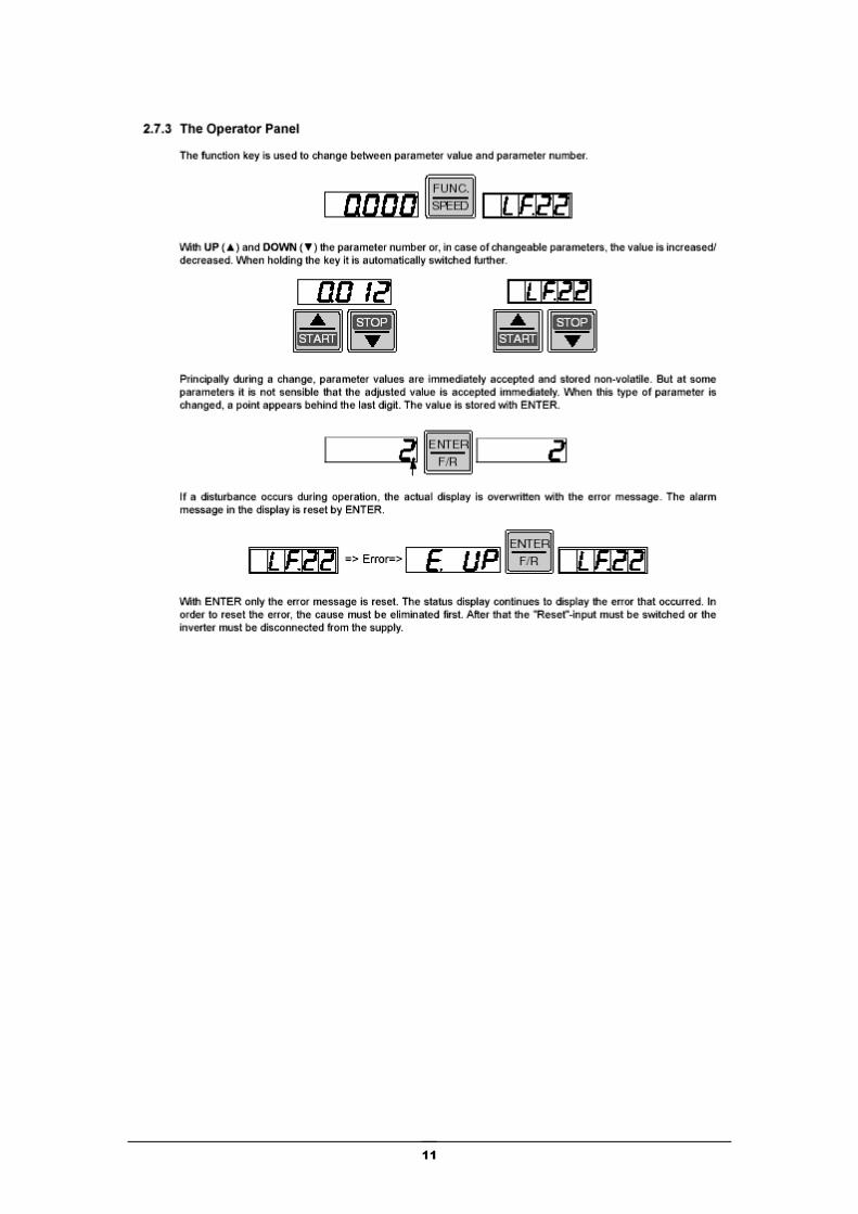
• LF Parameters. Lift specific adjustments Refer to the following diagram 2.7.3 for detail on how to use the Digital Operator.
11
12
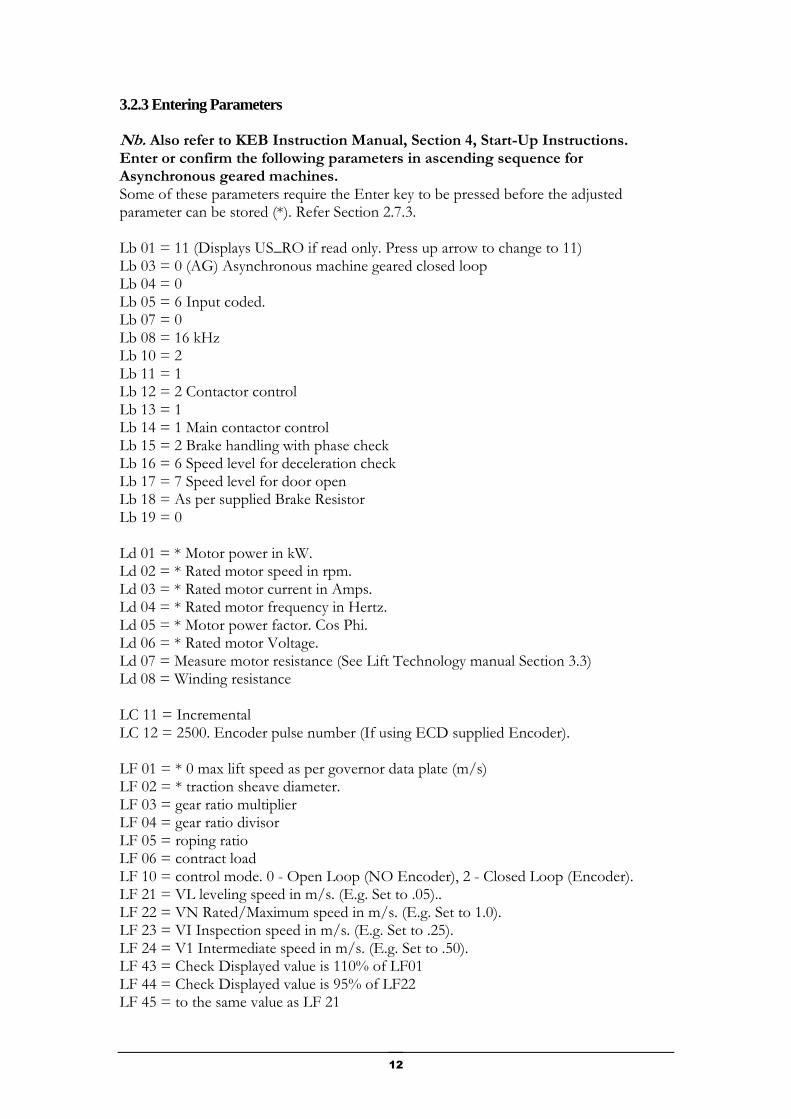
3.2.3 Entering Parameters Nb. Also refer to KEB Instruction Manual, Section 4, Start-Up Instructions. Enter or confirm the following parameters in ascending sequence for Asynchronous geared machines. Some of these parameters require the Enter key to be pressed before the adjusted parameter can be stored (*). Refer Section 2.7.3. Lb 01 = 11 (Displays US_RO if read only. Press up arrow to change to 11) Lb 03 = 0 (AG) Asynchronous machine geared closed loop Lb 04 = 0 Lb 05 = 6 Input coded. Lb 07 = 0 Lb 08 = 16 kHz Lb 10 = 2 Lb 11 = 1 Lb 12 = 2 Contactor control Lb 13 = 1 Lb 14 = 1 Main contactor control Lb 15 = 2 Brake handling with phase check Lb 16 = 6 Speed level for deceleration check Lb 17 = 7 Speed level for door open Lb 18 = As per supplied Brake Resistor Lb 19 = 0 Ld 01 = * Motor power in kW. Ld 02 = * Rated motor speed in rpm. Ld 03 = * Rated motor current in Amps. Ld 04 = * Rated motor frequency in Hertz. Ld 05 = * Motor power factor. Cos Phi. Ld 06 = * Rated motor Voltage. Ld 07 = Measure motor resistance (See Lift Technology manual Section 3.3) Ld 08 = Winding resistance LC 11 = Incremental LC 12 = 2500. Encoder pulse number (If using ECD supplied Encoder). LF 01 = * 0 max lift speed as per governor data plate (m/s) LF 02 = * traction sheave diameter. LF 03 = gear ratio multiplier LF 04 = gear ratio divisor LF 05 = roping ratio LF 06 = contract load LF 10 = control mode. 0 - Open Loop (NO Encoder), 2 - Closed Loop (Encoder). LF 21 = VL leveling speed in m/s. (E.g. Set to .05).. LF 22 = VN Rated/Maximum speed in m/s. (E.g. Set to 1.0). LF 23 = VI Inspection speed in m/s. (E.g. Set to .25). LF 24 = V1 Intermediate speed in m/s. (E.g. Set to .50). LF 43 = Check Displayed value is 110% of LF01 LF 44 = Check Displayed value is 95% of LF22 LF 45 = to the same value as LF 21
13
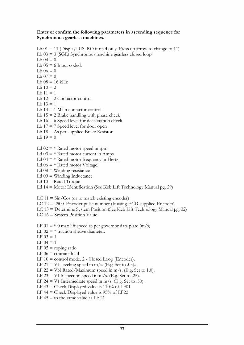
Enter or confirm the following parameters in ascending sequence for Synchronous gearless machines. Lb 01 = 11 (Displays US_RO if read only. Press up arrow to change to 11) Lb 03 = 3 (SGL) Synchronous machine gearless closed loop Lb 04 = 0 Lb 05 = 6 Input coded. Lb 06 = 0 Lb 07 = 0 Lb 08 = 16 kHz Lb 10 = 2 Lb 11 = 1 Lb 12 = 2 Contactor control Lb 13 = 1 Lb 14 = 1 Main contactor control Lb 15 = 2 Brake handling with phase check Lb 16 = 6 Speed level for deceleration check Lb 17 = 7 Speed level for door open Lb 18 = As per supplied Brake Resistor Lb 19 = 0 Ld 02 = * Rated motor speed in rpm. Ld 03 = * Rated motor current in Amps. Ld 04 = * Rated motor frequency in Hertz. Ld 06 = * Rated motor Voltage. Ld 08 = Winding resistance Ld 09 = Winding Inductance Ld 10 = Rated Torque Ld 14 = Motor Identification (See Keb Lift Technology Manual pg. 29) LC 11 = Sin/Cos (or to match existing encoder) LC 12 = 2500. Encoder pulse number (If using ECD supplied Encoder). LC 15 = Determine System Position (See Keb Lift Technology Manual pg. 32) LC 16 = System Position Value LF 01 = * 0 max lift speed as per governor data plate (m/s) LF 02 = * traction sheave diameter. LF 03 = 1 LF 04 = 1 LF 05 = roping ratio LF 06 = contract load LF 10 = control mode. 2 - Closed Loop (Encoder). LF 21 = VL leveling speed in m/s. (E.g. Set to .05).. LF 22 = VN Rated/Maximum speed in m/s. (E.g. Set to 1.0). LF 23 = VI Inspection speed in m/s. (E.g. Set to .25). LF 24 = V1 Intermediate speed in m/s. (E.g. Set to .50). LF 43 = Check Displayed value is 110% of LF01 LF 44 = Check Displayed value is 95% of LF22 LF 45 = to the same value as LF 21
14
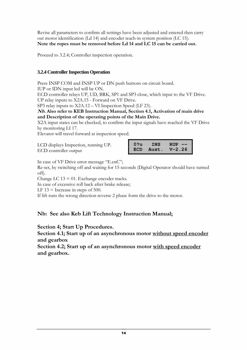
Revise all parameters to confirm all settings have been adjusted and entered then carry out motor identification (Ld 14) and encoder teach-in system position (LC 15). Note the ropes must be removed before Ld 14 and LC 15 can be carried out. Proceed to 3.2.4; Controller inspection operation. 3.2.4 Controller Inspection Operation Press INSP COM and INSP UP or DN push buttons on circuit board. IUP or IDN input led will be ON. ECD controller relays UP, UD, BRK, SP1 and SP3 close, which input to the VF Drive. UP relay inputs to X2A.15 - Forward on VF Drive. SP3 relay inputs to X2A.12 – VI Inspection Speed (LF 23). Nb. Also refer to KEB Instruction Manual, Section 4.1, Activation of main drive and Description of the operating points of the Main Drive. X2A input states can be checked, to confirm the input signals have reached the VF Drive by monitoring LI 17. Elevator will travel forward at inspection speed. LCD displays Inspection, running UP. ECD controller output In case of VF Drive error message “E.enC”; Re-set, by switching off and waiting for 15 seconds (Digital Operator should have turned off). Change LC 13 = 01. Exchange encoder tracks. In case of excessive roll back after brake release; LF 13 = Increase in steps of 500. If lift runs the wrong direction reverse 2 phase form the drive to the motor.
Nb: See also Keb Lift Technology Instruction Manual; Section 4; Start Up Procedures. Section 4.1; Start up of an asynchronous motor without speed encoder and gearbox Section 4.2; Start up of an asynchronous motor with speed encoder and gearbox.
0?u INS RUP -- ECD Aust. V-2.26
15
Section 4. Full Speed Running 4.1 Confirmations Ensure SIS has been installed. See Section 2.2.4 Care should be taken to make sure that the magnet placement is as per page 5 of the circuit diagram. Note pay particular attention to the X and Y distances. If the machine is to be driven closed loop, ensure the encoder has been mounted correctly and parameter LF 10 = 2. 4.2 SIS Sequence Confirmation The lift should now be driven top to bottom and bottom to top on inspection and the following inputs should be observed to confirm there operation: TSL, BSL, MSU, MSD, DZ, (and DZR if there are rear doors). It is important to make sure that all these inputs trigger at the correct times;
• TSL and BSL for terminal floor correction. Ensures lift slows at terminal floors by dropping fast speed command to drive
• On approach to the bottom floor MSD must come on just before BSL turns off.
• On approach to the top floor MSU must come on just before TSL turns off.
• Approaching floor level in the up direction you should get DZ then MSU then MSD. DZ must mask MSU and MSD at floor level.
• Approaching floor level in the down direction you should get DZ then MSD then MSU. DZ must mask MSU and MSD at floor level.
• In between floors there should be 1 MSU and 1 MSD.
Before proceeding ensure the actual running speed of the lift is running at contract/rated speed. Check with handheld tacho. Nb: If slowdown limits, magnets and accel/decel rates are adjusted and lift is not traveling at contract speed, they will all have to be re done again later when the speed is increased to the correct level.
Section
4
16
4.2.1 Correction Run The lift can now be switched to auto but it is recommended that the DDO switch be turned on to ensure the doors do not open. Now the controller should do a correction run and slow on approach to the bottom floor, when BSL limit is activated (loss of BSL input on 100-173/4 board). Lift should level in and stop when DZ, MSU and MSD input come on. Once this has been done send the lift to the second top floor and observe operation. 4.2.2 Ride Quality The next step is to adjust the acceleration and deceleration rates to achieve the desired ride quality. See graph page 40 in F5 Lift Technology manual for these settings. Brake lift settings may also be adjusted in the drive to reduce jerk when starting. 4.2.3 Floor Levels Adjust the MSU and MSD slowing magnets to ensure lift decelerates in time to reach leveling speed. It is suggested that approximately 50mm of leveling speed be achieved in both directions for best floor accuracy. Adjust the leveling speed in conjunction with the magnets to provide correct floor level. Brake drop settings may also be adjusted to improve final stop. 4.2.4 Emergency Terminal Slowdown If the rated lift speed is above 1m/s then the SPD (Speed) and ETS (Emergency Terminal Slowdown) circuits must be used. These circuits are used to ensure that the elevator has decelerated on approach to the terminal floor. SPD relay is wired to terminal X2A.18 of the Keb drive (see p2 of prints) When lift actual speed is below the value set in Parameter LF.44 of the Keb drive the SPD relay will be energized. SPD relay provides over bridging of the ETS limits shown on pg4 of the prints. I.e. If the elevator is traveling below the speed set in LF.44 when it opens the ETS limit in the shaft it will continue to run but if it is traveling above the speed set in LF.44 when an ETS limit opens, the safety circuit is then opened causing an emergency stop. The ETS limits (limit switches, reed switches or bi-stable switches) need to be positioned inside of the terminal slow down limits (TSL and BSL) but at a reasonable distance from the floor level. There positioning should allow for the lift to decelerated to below 90% of rated speed before they are triggered in a normal slowdown situation.

17
Section 5. Combivis Software 5.1 Installation and Setup Combivis 5
5.1.1 Software Install When connecting a pc with Combivis Software to a drive it is recommended use the following procedure:
• Load Combivis program into pc
1. At autorun screen select A Install Combivis 5 2. At Combivis setup selector select Complete 3. At the next screen press Finish 4. When the Choose Setup Language Dialog appears select English 5. Press OK 6. Press Next 7. At the Select Components screen select UK 8. At the next screen press Next 9. At the next screen press Next 10. At the next screen press Next 11. At the next screen press Finish 12. Wait for the Quit Button to highlight then press Quit 13. Hit the ESC button to terminate the Auto run screen 14. Turn the pc off
• Power down drive and install Serial loader module
• Connect all supplied cables to drive and pc
• Turn drive back on
• Turn on pc
• Start Combivis program
• Communication should now be established automatically
5.1.2 Communication Faults If communication is not established use the following to check the serial port
settings.
• Press No to Search on different Baud Rates See Fig 1
• Press No to load an inverter type See Fig 2
• Press Yes to start an empty Project See Fig 3
• Goto the EDIT Menu
• Select Configuration
Section
5
18
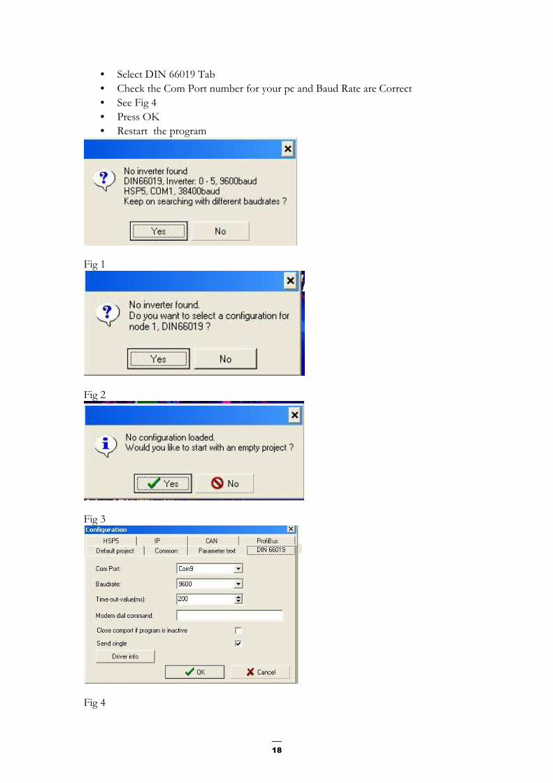
• Select DIN 66019 Tab
• Check the Com Port number for your pc and Baud Rate are Correct
• See Fig 4
• Press OK
• Restart the program
Fig 1
Fig 2
Fig 3
Fig 4
19
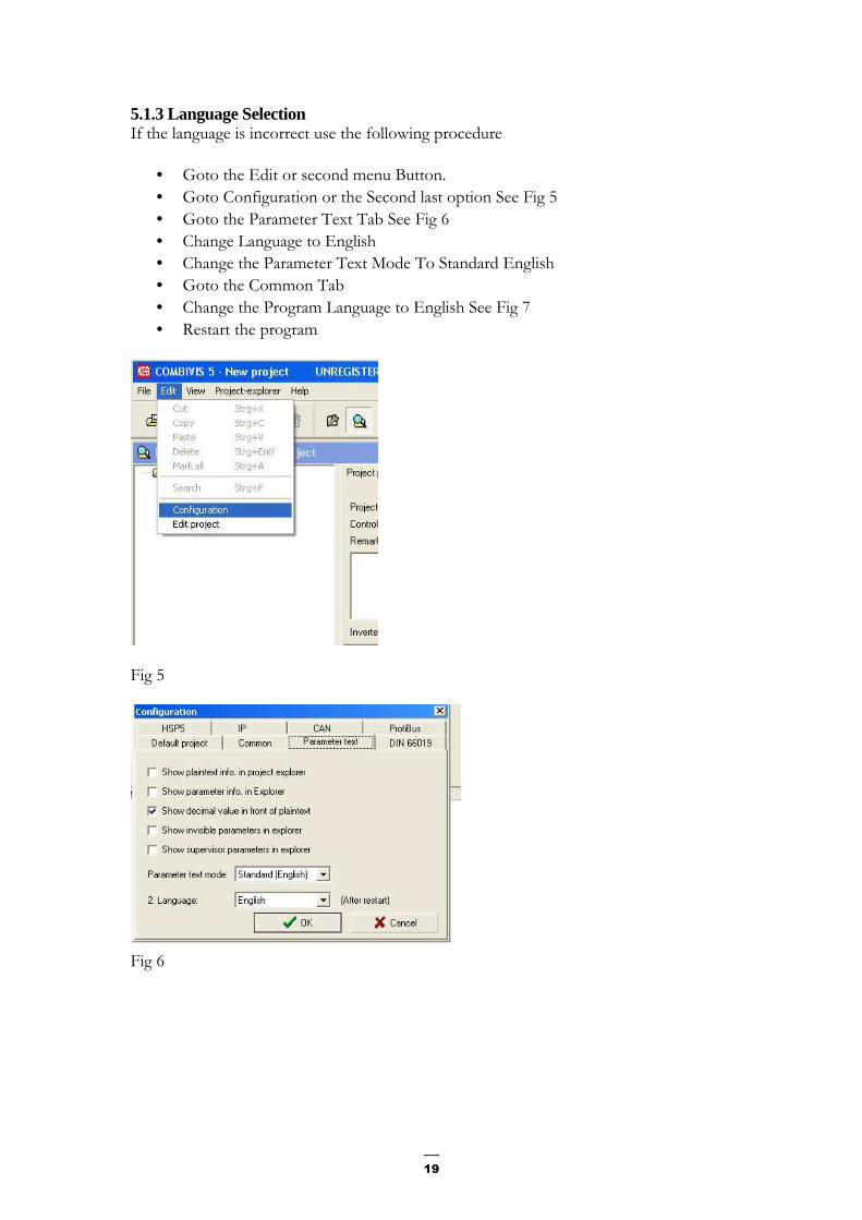
5.1.3 Language Selection If the language is incorrect use the following procedure
• Goto the Edit or second menu Button.
• Goto Configuration or the Second last option See Fig 5
• Goto the Parameter Text Tab See Fig 6
• Change Language to English
• Change the Parameter Text Mode To Standard English
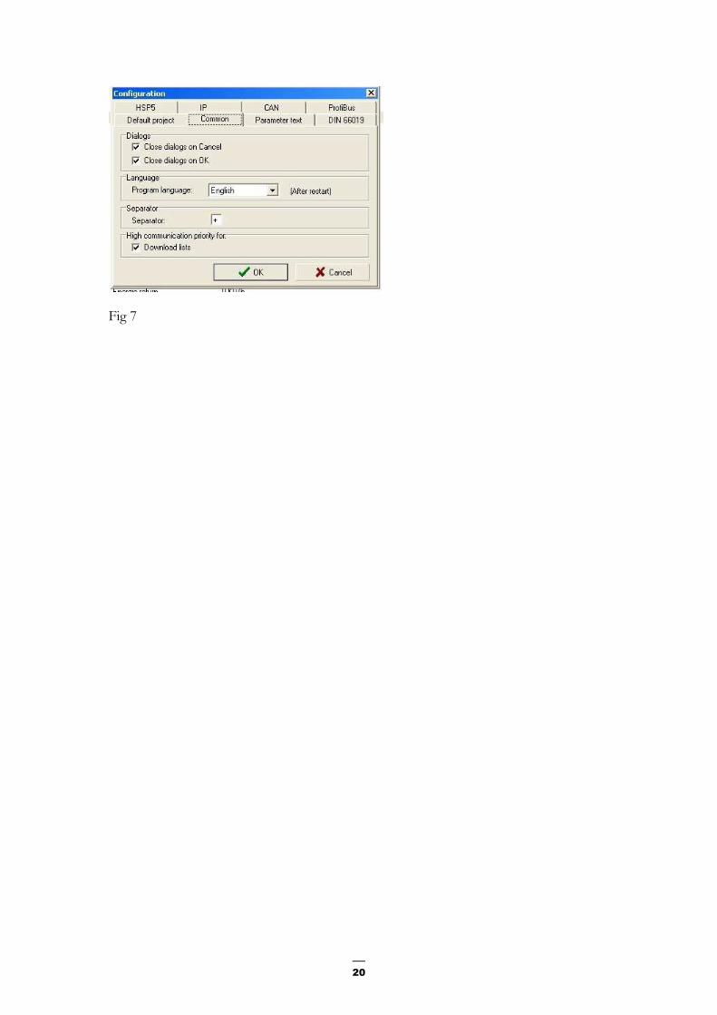
• Goto the Common Tab
• Change the Program Language to English See Fig 7
• Restart the program
Fig 5
Fig 6
20
Fig 7
21
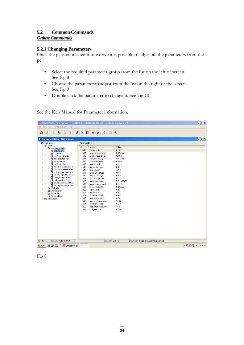
5.2 Common Commands Online Commands 5.2.1 Changing Parameters Once the pc is connected to the drive it is possible to adjust all the parameters from the pc.
• Select the required parameter group from the list on the left of screen See Fig 8
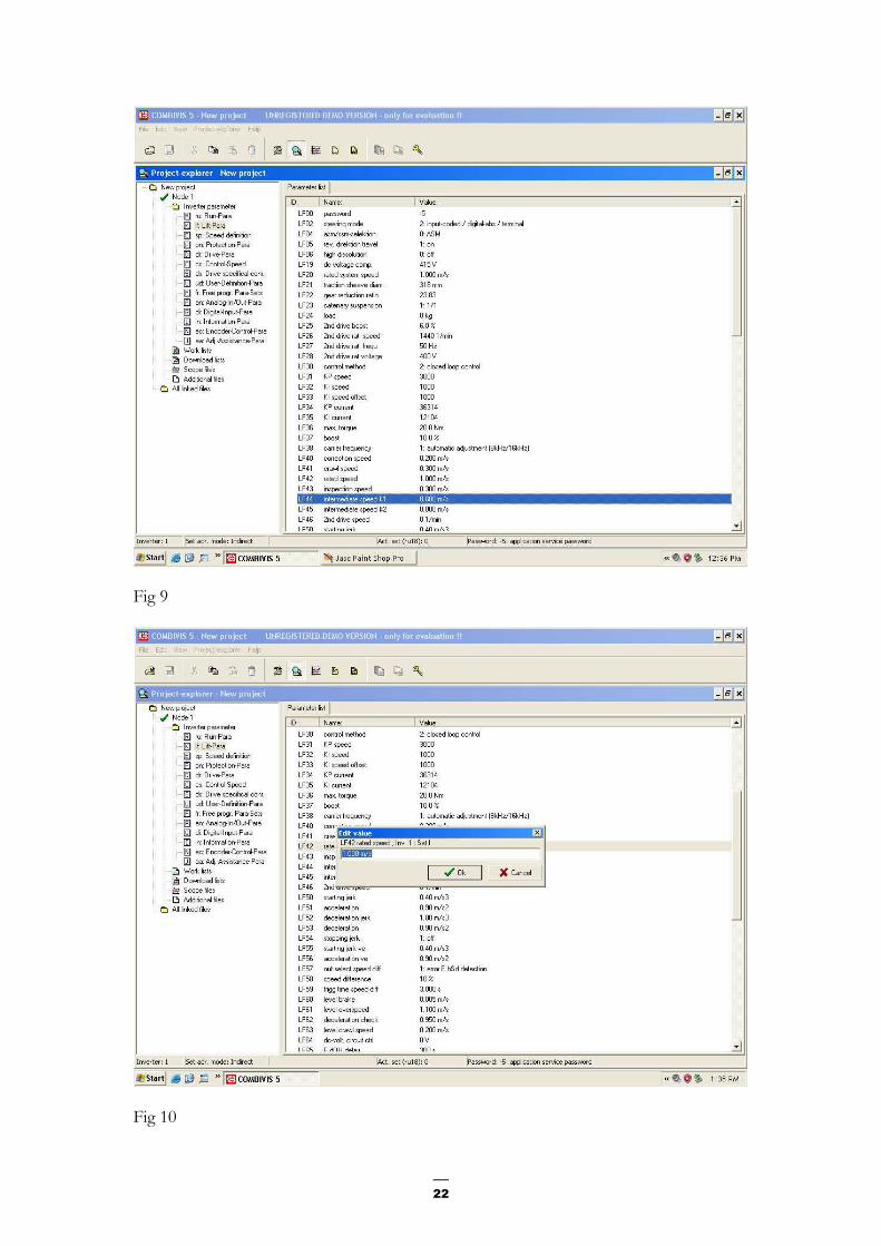
• Choose the parameter to adjust from the list on the right of the screen See Fig 9
• Double click the parameter to change it. See Fig 10 See the Keb Manual for Parameter information.
Fig 8
22
Fig 9
Fig 10

23
5.2.2 Upload parameter list from inverter
• File -New Project
• File –Parameter Saving
• Inverter1/Node1-OK
• Upload/Download in progress
• Ignore
• OK
• Save as E.G Schindler.dw5 5.2.3 Download a parameter list to a drive
• File-Open
• Select file name
• OK
• Goto file name Heading
• Download to Inverter
• Yes
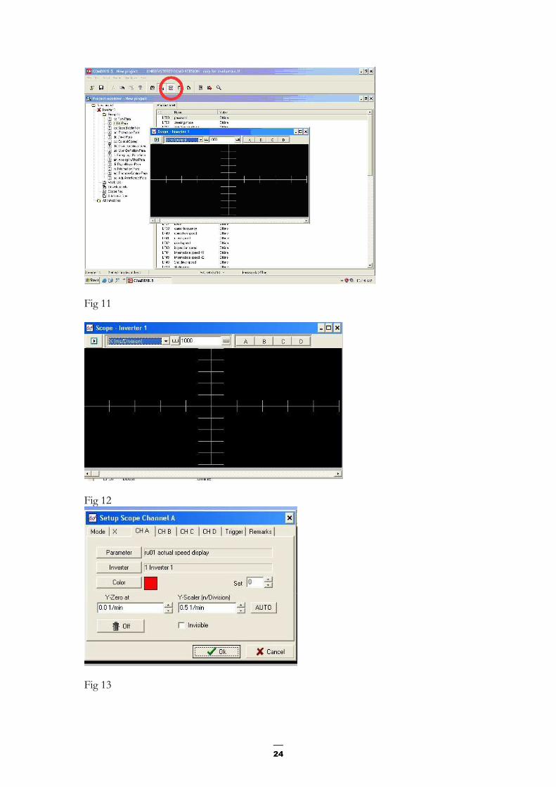
• OK 5.2.3 To reload the default drive settings to F4 contact ECD Parameter Value UD 01 xxxx FR 01 -2 initialize all sets 5.2.4 Oscilloscope Functions The software has a built in oscilloscope function which has 4 programmable channels. To enable the Scope use the following steps
• Start Combivis Program
• Goto View , Scope See Fig 11
• The next step is to configure the channels of the scope
• Choose the desired channel e.g. A, B, C or D See Fig 12
• Goto Parameter See Fig 13
• Choose the correct parameter for what you wish to monitor
• OK
• Next choose the Scale for the Channel
• OK
• To start the Scope Press the Play Button
• To stop the display Press the Stop Button This will display real-time information
24
Fig 11
Fig 12
Fig 13
25
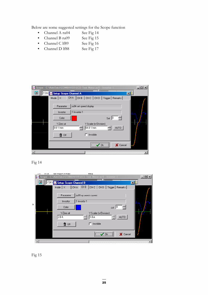
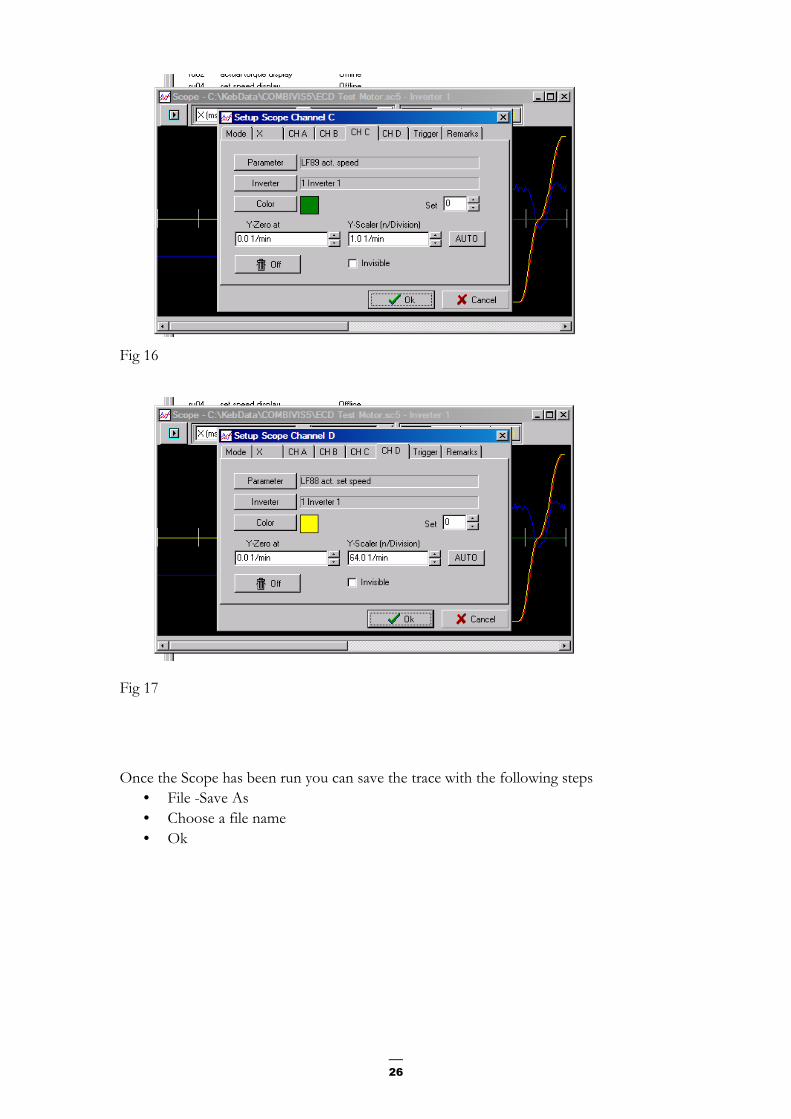
Below are some suggested settings for the Scope function
• Channel A ru04 See Fig 14
• Channel B ru09 See Fig 15
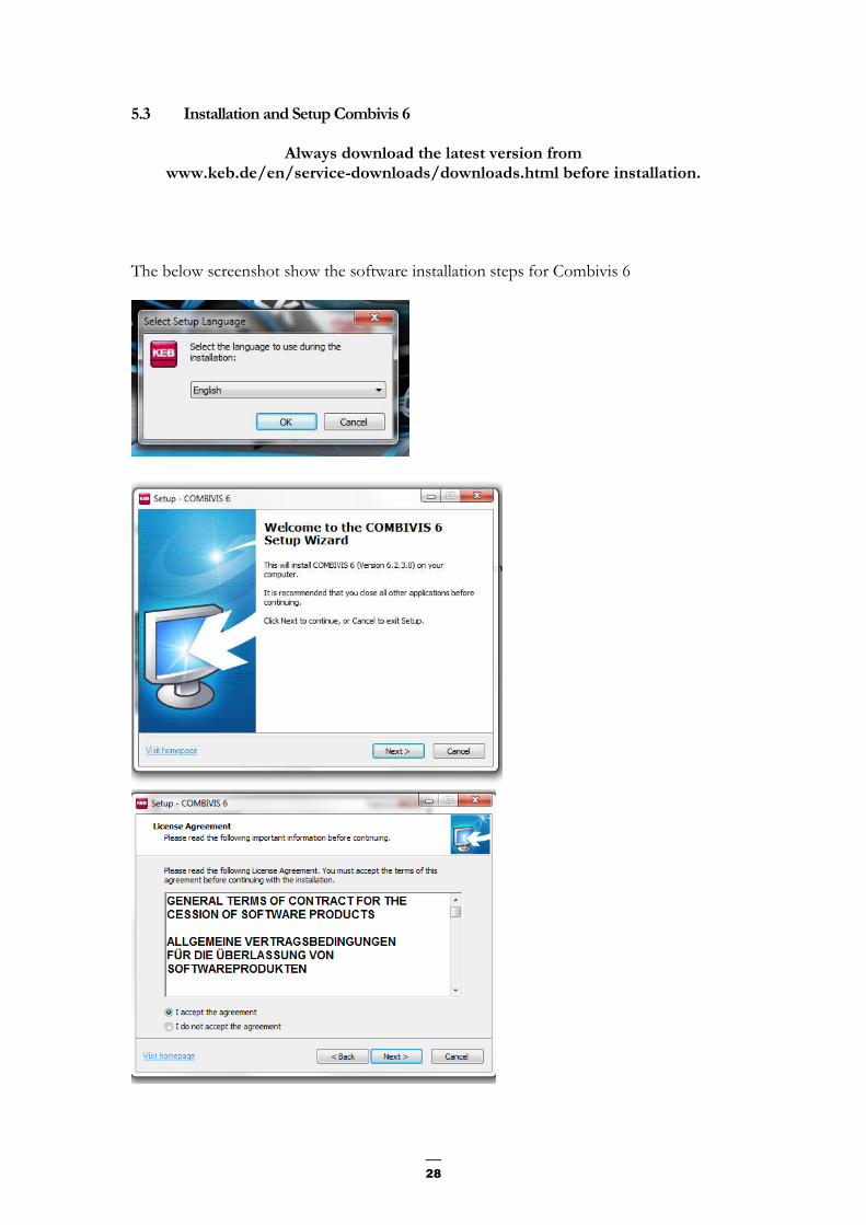
• Channel C lf89 See Fig 16
• Channel D lf88 See Fig 17
Fig 14
Fig 15
26
Fig 16
Fig 17 Once the Scope has been run you can save the trace with the following steps
• File -Save As
• Choose a file name
• Ok

27
Offline Commands 5.2.5 To view a saved Parameter List
• File-Open
• Select the desired file
• Open
• Press yes on new parameter list
• OK 5.2.6 To View a saved Scope Trace
• File-Open
• Select the desired file
• Open
• Yes
• Ok
28
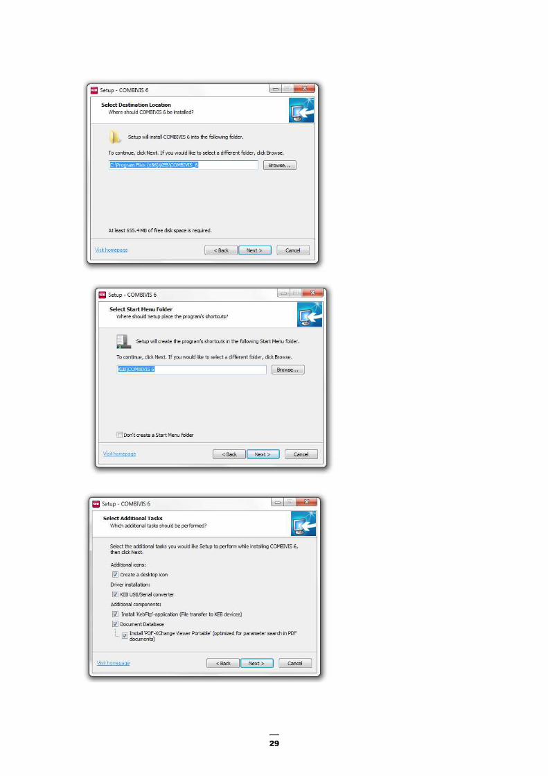
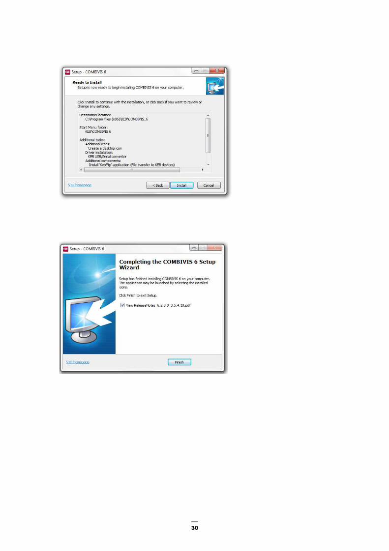
5.3 Installation and Setup Combivis 6
Always download the latest version from www.keb.de/en/service-downloads/downloads.html before installation.
The below screenshot show the software installation steps for Combivis 6
29
30

31
Electronic Circuit Designs Pty. Ltd. Factory 11/30 Perry Street • Matraville • NSW • Australia • 2036
Phone 61 2 9316 6909 • Fax 61 2 9316 6797 Email [email protected] Web www.ecd.com.au


![a fu titel gb - Electrónica Indústrialelectronicaindustrial.pt/application/uploads/files/00f5bemka02[1].pdf · 2 This manual describes the KEB COMBIVERT F5. Particular attention](https://img.pdfslide.us/doc/110x75/5b4310417f8b9ab15f8baa97/a-fu-titel-gb-electronica-industriale-1pdf-2-this-manual-describes-the.jpg)