Embed Size (px)
Citation preview
C O M B I V E R T
Original ManualMat.No. Rev.00G6NEL-0B00 1D
GB Installation Manual Housing B Power Unit Power 4.0…5.5 kW

GB - 3
Table of Contents
1. Preface ..............................................................................................................51.1 General ................................................................................................................................. 51.2 Validity and liability ............................................................................................................. 51.3 Copyright .............................................................................................................................. 61.4 Specifiedapplication ........................................................................................................... 61.5 Product description ............................................................................................................. 61.6 Part Code .............................................................................................................................. 71.7 Safety and operating instructions ...................................................................................... 8
2. Technical Data .................................................................................................92.1 Operating conditions ........................................................................................................... 92.2 Technical data G6 400V class ........................................................................................... 102.3 Mechanical installation ..................................................................................................... 122.3.2 Dimensions and weights ...................................................................................................... 122.3.3 Control cabinet installation ................................................................................................... 13
3. Installation and Connection .........................................................................143.1 Overview of the COMBIVERT G6 ...................................................................................... 143.2 Connection of the power unit ........................................................................................... 153.2.1 Connection of the voltage supply ......................................................................................... 153.2.1.1 Wiring instructions ............................................................................................................... 153.2.1.2 AC supply 400V / 3-phase ................................................................................................... 163.2.1.3 Line terminal strip X1A ......................................................................................................... 163.2.1.4 Supply cable ........................................................................................................................ 163.2.1.5 Connection at DC voltage supply ........................................................................................ 173.2.1.6 Terminal strip X1B DC connection ....................................................................................... 173.2.2 Connection of the motor ...................................................................................................... 173.2.2.1 Selection of the motor cable ................................................................................................ 173.2.2.2 Motor line length at operation with DC voltage .................................................................... 173.2.2.3 Cable-fed disturbances depending on the motor line length at AC supply .......................... 183.2.2.4 Motor cable cross-section .................................................................................................... 183.2.2.5 Interconnection of the motor ................................................................................................ 183.2.2.6 Terminal strip X1B motor connection ................................................................................... 183.2.2.7 Wiring of the motor .............................................................................................................. 193.2.3 Connection of a braking resistor .......................................................................................... 193.2.3.1 Terminal strip X1B connection braking resistor .................................................................... 193.2.3.2 Wiring of an intrinsically safe braking resistor ...................................................................... 193.2.3.3 Using a non-intrinsically safe braking resistor ..................................................................... 193.2.4.1 Temperature detection terminals T1, T2 .............................................................................. 203.2.4.2 Terminal strip X1C temperature detection ........................................................................... 203.2.4.3 Use of the temperature input in PTC mode ......................................................................... 203.2.5 Final test informations of the machines/systems which are provided with frequency
inverters according to EN 60204 Part 1 of 2007 .................................................................. 213.2.5.1 Voltage test (in accordance with EN60204-1 chapter 18.4) ................................................. 213.2.5.2 Isolation resistance measurement (in accordance with EN60204-1 chapter 18.3) .............. 21
Annex A .....................................................................................................................22

GB - 4
Table of Contents
A.1 Calculation of the motor voltage ...................................................................................... 22A.2 Maintenance ....................................................................................................................... 22A.3 Shut down .......................................................................................................................... 23A.3.1 Storage ................................................................................................................................ 23
Annex B .....................................................................................................................24B.1 Certification ........................................................................................................................ 24B.1.1 CE-Marking .......................................................................................................................... 24B.1.2 UL Marking........................................................................................................................... 24B.2 Further informations and documentation ....................................................................... 26
GB - 5
Preface
1. Preface1.1 General
First we would like to welcome you as a customer of KEB and congratulation to the purchase of this product. You have decided for a product on highest technical niveau. The described hard- and software are developments of the Karl E. Brinkmann GmbH. The enclosed documents correspond to conditions valid at printing. Misprint, mistakes and tech-nical changes reserved. The instruction manual must be made available to the user. Prior to performing any work on the unit the user must familiarize himself with the unit. This especially applies to the know-ledge and observance of the following safety and warning indications. The used pictograms have following significance:
Danger Is used when the life or health of the user is in danger or con-siderable damage to property can occur.Warning
Caution
Attention Is used when a measure is necesary for safe and disturbance free operation.observe at
all costs
Information Is used, if a measure simplifies the handling or operation of the unit.Aide
Tip
Non-observance of the safety instructions leads to the loss of any liability claims. This list is not exhaustive.
1.2 Validity and liabilityThe use of our units in the target products is outside of our control and therefore lies exclusively in the area of responsibility of the machine manufacturer.The information contained in the technical documentation, as well as any user-specific advice in spoken and written and through tests, are made to best of our knowledge and information about the application. However, they are considered for information only without responsibili-ty. This also applies to any violation of industrial property rights of a third-party.Selection of our units in view of their suitability for the intended use must be done generally by the user. Tests can only be done within the application by the machine manufacturer. They must be repeated, even if only parts of hardware, software or the unit adjustment are modified. Unauthorised opening and tampering may lead to bodily injury and property damage and may entail the loss of warranty rights. Original spare parts and authorized accessories by the manufacturer serve as security. The use of other parts excludes liability for the consequences arising out of.The suspension of liability is especially valid also for operation interruption loss, loss of profit, data loss or other damages. This is also valid, if we referred first to the possibility of such damages.
GB - 6
Preface
If single regulations should be or become void, invalid or impracticable, the effectivity of all other regulations or agreements is not affected.
1.3 CopyrightThe customer may use the instruction manual as well as further documents or parts from it for internal purposes. Copyrights are with KEB and remain valid in its entirety.
1.4 SpecifiedapplicationThe COMBIVERT G6 serves exclusively for the control and regulation of three-phase motors. The operation of other electric consumers is prohibited and can lead to the destruction of the unit. Frequency inverter are components which are intended for the installation in electric systems or machines.The used semiconductors and components of KEB are developed and dimensioned for the use in industrial products. If the KEB COMBIVERT F5 is used in machines, which work under exceptional conditions or if essential functions, life-supporting measures or an extraordinary safety step must be fulfilled, the necessary reliability and security must be ensured by the ma-chine builder. The operation of our products outside the indicated limit values of the technical data leads to the loss of any liability claims.
1.5 Product descriptionThe product family COMBIVERT G6 has been developed for the universal use at open-loop three-phase drives. The units are equipped with an integrated EMC filter. This manual descri-bes only the power circuits.
This accompanying instruction manual contains only information for the installa-tion and connection of the power circuit KEB COMBIVERT G6. Further parts of the installation manual are required depending on the ordered type:• Connection and adjustments of the control• Safety function STO• Safe digital output for f=0Hz
A manual with general safety requirements and EMC conform installation is available under www.keb.de.
GB - 7
Preface
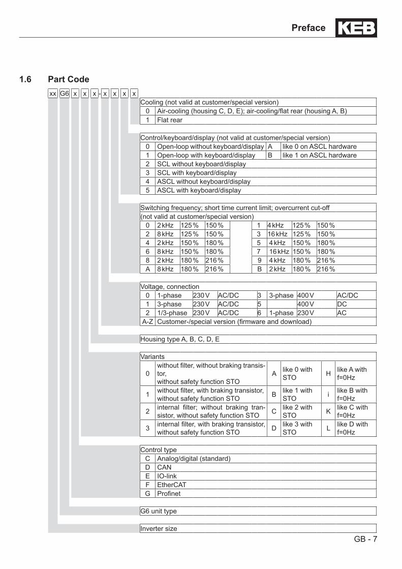
1.6 Part Codexx G6 x x x - x x x x
Cooling (not valid at customer/special version)0 Air-cooling (housing C, D, E); air-cooling/flat rear (housing A, B)1 Flat rear
Control/keyboard/display (not valid at customer/special version)0 Open-loop without keyboard/display A like 0 on ASCL hardware1 Open-loop with keyboard/display B like 1 on ASCL hardware2 SCL without keyboard/display3 SCL with keyboard/display4 ASCL without keyboard/display5 ASCL with keyboard/display
Switching frequency; short time current limit; overcurrent cut-off(not valid at customer/special version)
0 2 kHz 125 % 150 % 1 4 kHz 125 % 150 %2 8 kHz 125 % 150 % 3 16 kHz 125 % 150 %4 2 kHz 150 % 180 % 5 4 kHz 150 % 180 %6 8 kHz 150 % 180 % 7 16 kHz 150 % 180 %8 2 kHz 180 % 216 % 9 4 kHz 180 % 216 %A 8 kHz 180 % 216 % B 2 kHz 180 % 216 %
Voltage, connection0 1-phase 230 V AC/DC 3 3-phase 400 V AC/DC1 3-phase 230 V AC/DC 5 400 V DC2 1/3-phase 230 V AC/DC 6 1-phase 230 V AC
A-Z Customer-/special version (firmware and download)
Housing type A, B, C, D, E
Variants
0without filter, without braking transis-tor, without safety function STO
A like 0 with STO H like A with
f=0Hz
1 without filter, with braking transistor, without safety function STO B like 1 with
STO i like B with f=0Hz
2 internal filter; without braking tran-sistor, without safety function STO C like 2 with
STO K like C with f=0Hz
3 internal filter, with braking transistor, without safety function STO D like 3 with
STO L like D with f=0Hz
Control typeC Analog/digital (standard)D CANE IO-linkF EtherCATG Profinet
G6 unit type
Inverter size
GB - 8
Safety Instructions
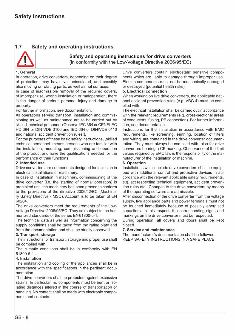
1. GeneralIn operation, drive converters, depending on their degree of protection, may have live, uninsulated, and possibly also moving or rotating parts, as well as hot surfaces.In case of inadmissible removal of the required covers, of improper use, wrong installation or maloperation, there is the danger of serious personal injury and damage to property.For further information, see documentation.All operations serving transport, installation and commis-sioning as well as maintenance are to be carried out by skilled technical personnel (Observe IEC 364 or CENELEC HD 384 or DIN VDE 0100 and IEC 664 or DIN/VDE 0110 and national accident prevention rules!).For the purposes of these basic safety instructions, „skilled technical personnel“ means persons who are familiar with the installation, mounting, commissioning and operation of the product and have the qualifications needed for the performance of their functions.2. Intended useDrive converters are components designed for inclusion in electrical installations or machinery.In case of installation in machinery, commissioning of the drive converter (i.e. the starting of normal operation) is prohibited until the machinery has been proved to conform to the provisions of the directive 2006/42/EC (Machine-ry Safety Directive - MSD). Account is to be taken of EN 60204.The drive converters meet the requirements of the Low-Voltage Directive 2006/95/EC. They are subject to the har-monized standards of the series EN 61800-5-1.The technical data as well as information concerning the supply conditions shall be taken from the rating plate and from the documentation and shall be strictly observed.3. Transport, storageThe instructions for transport, storage and proper use shall be complied with.The climatic conditions shall be in conformity with EN 61800-5-1 .4. InstallationThe installation and cooling of the appliances shall be in accordance with the specifications in the pertinent docu-mentation.The drive converters shall be protected against excessive strains. In particular, no components must be bent or iso-lating distances altered in the course of transportation or handling. No contact shall be made with electronic compo-nents and contacts.
1.7 Safety and operating instructions
Safety and operating instructions for drive converters(in conformity with the Low-Voltage Directive 2006/95/EC)
Drive converters contain electrostatic sensitive compo-nents which are liable to damage through improper use. Electric components must not be mechanically damaged or destroyed (potential health risks).5. Electrical connectionWhen working on live drive converters, the applicable nati-onal accident prevention rules (e.g. VBG 4) must be com-plied with.The electrical installation shall be carried out in accordance with the relevant requirements (e.g. cross-sectional areas of conductors, fusing, PE connection). For further informa-tion, see documentation. Instructions for the installation in accordance with EMC requirements, like screening, earthing, location of filters and wiring, are contained in the drive converter documen-tation. They must always be complied with, also for drive converters bearing a CE marking. Observance of the limit values required by EMC law is the responsibility of the ma-nufacturer of the installation or machine.6. OperationInstallations which include drive converters shall be equip-ped with additional control and protective devices in ac-cordance with the relevant applicable safety requirements, e.g. act respecting technical equipment, accident preven-tion rules etc.. Changes to the drive converters by means of the operating software are admissible.After disconnection of the drive converter from the voltage supply, live appliance parts and power terminals must not be touched immediately because of possibly energized capacitors. In this respect, the corresponding signs and markings on the drive converter must be respected. During operation, all covers and doors shall be kept closed.7. Service and maintenanceThe manufacturer’s documentation shall be followed.KEEP SAFETY INSTRUCTIONS IN A SAFE PLACE!
GB - 9
Technical Data
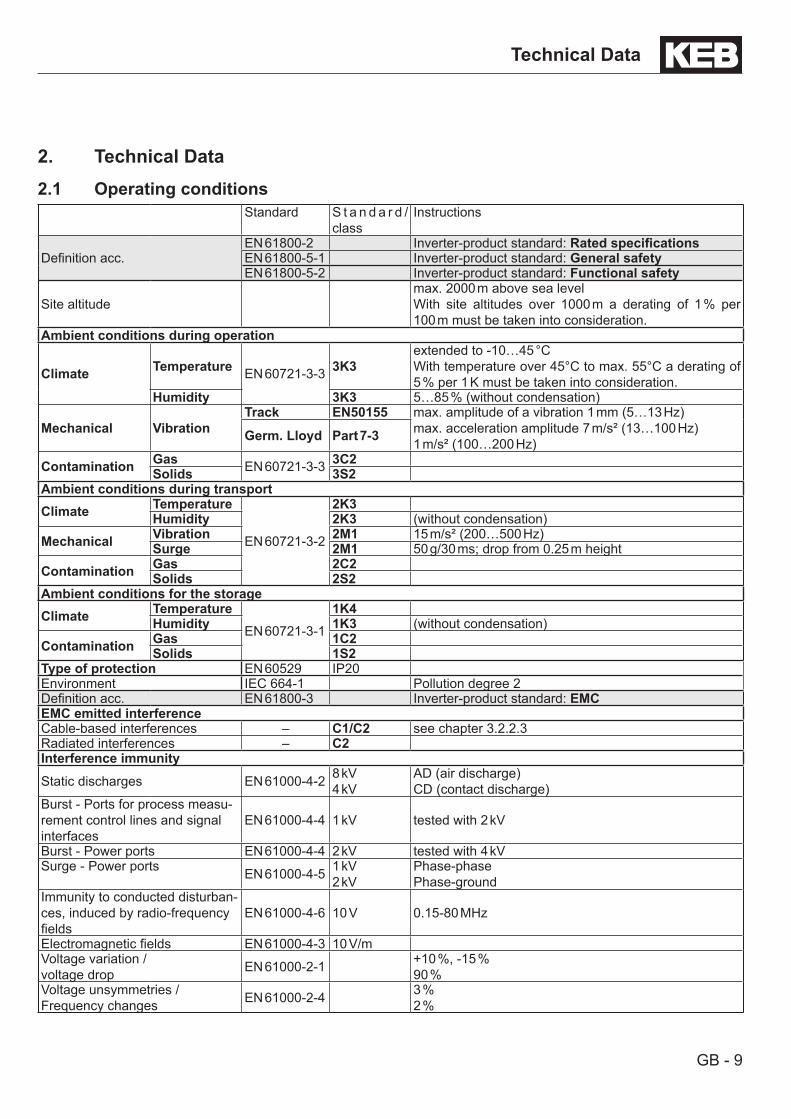
2. Technical Data2.1 Operating conditions
Standard S t a n d a r d /class
Instructions
Definition acc.EN 61800-2 Inverter-product standard: RatedspecificationsEN 61800-5-1 Inverter-product standard: General safetyEN 61800-5-2 Inverter-product standard: Functional safety
Site altitudemax. 2000 m above sea levelWith site altitudes over 1000 m a derating of 1 % per 100 m must be taken into consideration.
Ambient conditions during operation
Climate Temperature EN 60721-3-3 3K3extended to -10…45 °CWith temperature over 45°C to max. 55°C a derating of 5 % per 1 K must be taken into consideration.
Humidity 3K3 5…85 % (without condensation)
Mechanical VibrationTrack EN50155 max. amplitude of a vibration 1 mm (5…13 Hz)
max. acceleration amplitude 7 m/s² (13…100 Hz)1 m/s² (100…200 Hz)Germ. Lloyd Part 7-3
Contamination Gas EN 60721-3-3 3C2Solids 3S2
Ambient conditions during transportClimate Temperature
EN 60721-3-2
2K3Humidity 2K3 (without condensation)
Mechanical Vibration 2M1 15 m/s² (200…500 Hz)Surge 2M1 50 g/30 ms; drop from 0.25 m height
Contamination Gas 2C2Solids 2S2
Ambient conditions for the storageClimate Temperature
EN 60721-3-1
1K4Humidity 1K3 (without condensation)
Contamination Gas 1C2Solids 1S2
Type of protection EN 60529 IP20Environment IEC 664-1 Pollution degree 2Definition acc. EN 61800-3 Inverter-product standard: EMCEMC emitted interferenceCable-based interferences – C1/C2 see chapter 3.2.2.3Radiated interferences – C2Interference immunityStatic discharges EN 61000-4-2 8 kV
4 kVAD (air discharge)CD (contact discharge)
Burst - Ports for process measu-rement control lines and signal interfaces
EN 61000-4-4 1 kV tested with 2 kV
Burst - Power ports EN 61000-4-4 2 kV tested with 4 kVSurge - Power ports EN 61000-4-5 1 kV
2 kVPhase-phasePhase-ground
Immunity to conducted disturban-ces, induced by radio-frequency fields
EN 61000-4-6 10 V 0.15-80 MHz
Electromagnetic fields EN 61000-4-3 10 V/mVoltage variation /voltage drop EN 61000-2-1 +10 %, -15 %
90 %Voltage unsymmetries / Frequency changes EN 61000-2-4 3 %
2 %
GB - 10
Technical Data
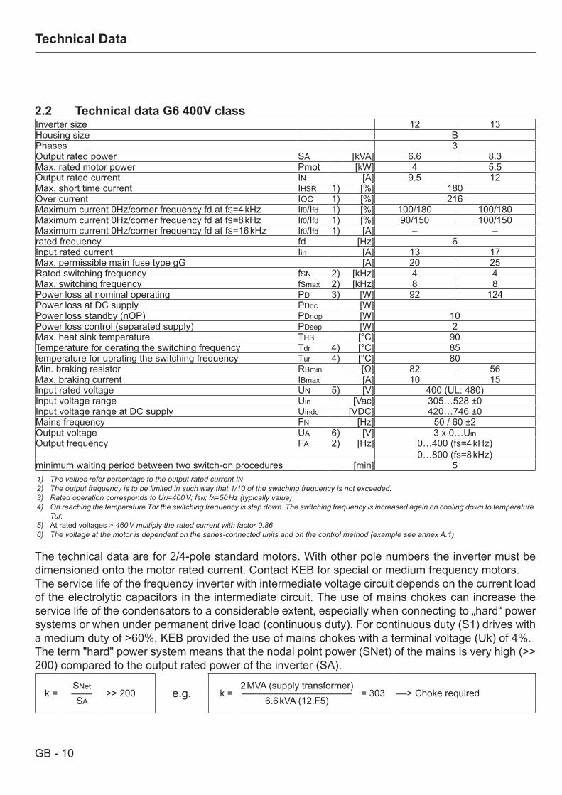
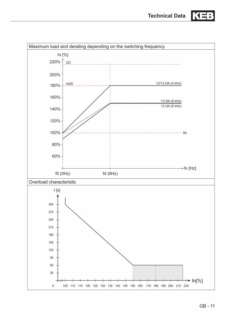
2.2 Technical data G6 400V classInverter size 12 13Housing size BPhases 3Output rated power SA [kVA] 6.6 8.3Max. rated motor power Pmot [kW] 4 5.5Output rated current IN [A] 9.5 12Max. short time current IHSR 1) [%] 180Over current IOC 1) [%] 216Maximum current 0Hz/corner frequency fd at fS=4 kHz If0/Ifd 1) [%] 100/180 100/180Maximum current 0Hz/corner frequency fd at fS=8 kHz If0/Ifd 1) [%] 90/150 100/150Maximum current 0Hz/corner frequency fd at fS=16 kHz If0/Ifd 1) [A] – –rated frequency fd [Hz] 6Input rated current Iin [A] 13 17Max. permissible main fuse type gG [A] 20 25Rated switching frequency fSN 2) [kHz] 4 4Max. switching frequency fSmax 2) [kHz] 8 8Power loss at nominal operating PD 3) [W] 92 124Power loss at DC supply PDdc [W]Power loss standby (nOP) PDnop [W] 10Power loss control (separated supply) PDsep [W] 2Max. heat sink temperature THS [°C] 90Temperature for derating the switching frequency Tdr 4) [°C] 85temperature for uprating the switching frequency Tur 4) [°C] 80Min. braking resistor RBmin [Ω] 82 56Max. braking current IBmax [A] 10 15Input rated voltage UN 5) [V] 400 (UL: 480)Input voltage range Uin [Vac] 305…528 ±0Input voltage range at DC supply Uindc [VDC] 420…746 ±0Mains frequency FN [Hz] 50 / 60 ±2Output voltage UA 6) [V] 3 x 0…UinOutput frequency FA 2) [Hz] 0…400 (fs=4 kHz)
0…800 (fs=8 kHz)minimum waiting period between two switch-on procedures [min] 51) The values refer percentage to the output rated current IN2) The output frequency is to be limited in such way that 1/10 of the switching frequency is not exceeded.3) Rated operation corresponds to UN=400 V; fSN; fA=50 Hz (typically value)4) On reaching the temperature Tdr the switching frequency is step down. The switching frequency is increased again on cooling down to temperature
Tur.5) At rated voltages > 460 V multiply the rated current with factor 0.866) The voltage at the motor is dependent on the series-connected units and on the control method (example see annex A.1)
The technical data are for 2/4-pole standard motors. With other pole numbers the inverter must be dimensioned onto the motor rated current. Contact KEB for special or medium frequency motors.The service life of the frequency inverter with intermediate voltage circuit depends on the current load of the electrolytic capacitors in the intermediate circuit. The use of mains chokes can increase the service life of the condensators to a considerable extent, especially when connecting to „hard“ power systems or when under permanent drive load (continuous duty). For continuous duty (S1) drives with a medium duty of >60%, KEB provided the use of mains chokes with a terminal voltage (Uk) of 4%.The term "hard" power system means that the nodal point power (SNet) of the mains is very high (>> 200) compared to the output rated power of the inverter (SA).
k =SNet 2 MVA (supply transformer)–––– >> 200 e.g. k = ––––––––––––––––––––– = 303 ––> Choke requiredSA 6.6 kVA (12.F5)
GB - 11
Technical Data
Maximum load and derating depending on the switching frequency
80%
60%
100%
120%
140%
160%
180%
200%
220%
fd (6Hz)f0 (0Hz)fA [Hz]
IN [%]
HSR
IN
OC
13.G6 (8 kHz)12.G6 (8 kHz)
12/13.G6 (4 kHz)
Overload characteristic
30
60
90
120
150
180
210
240
270
300
0 105 110 115 120 125 130 135 140 145 150 160 170 180 190 200 210 220IN[%]
t [s]
GB - 12
Mechanical Installation
2.3 Mechanical installation
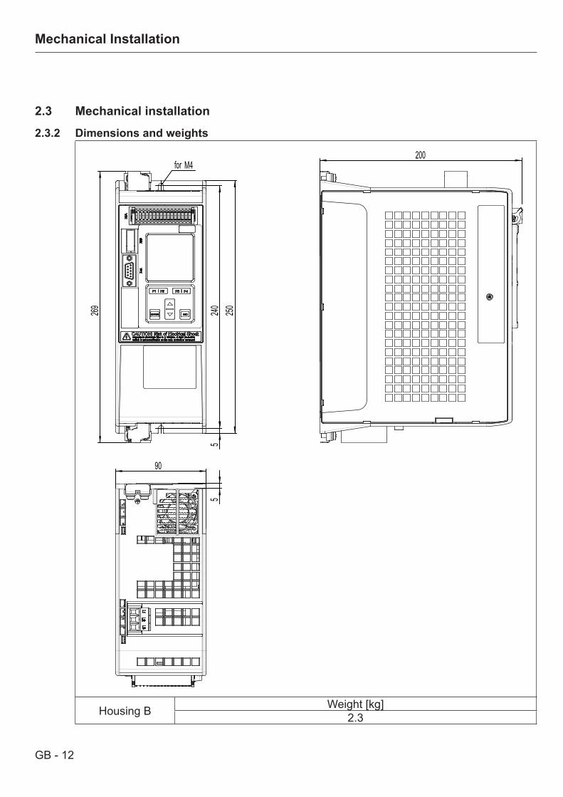
2.3.2 Dimensions and weights
269
525
024
0
for M4200
5
90
Housing B Weight [kg]2.3
GB - 13
Mechanical Installation
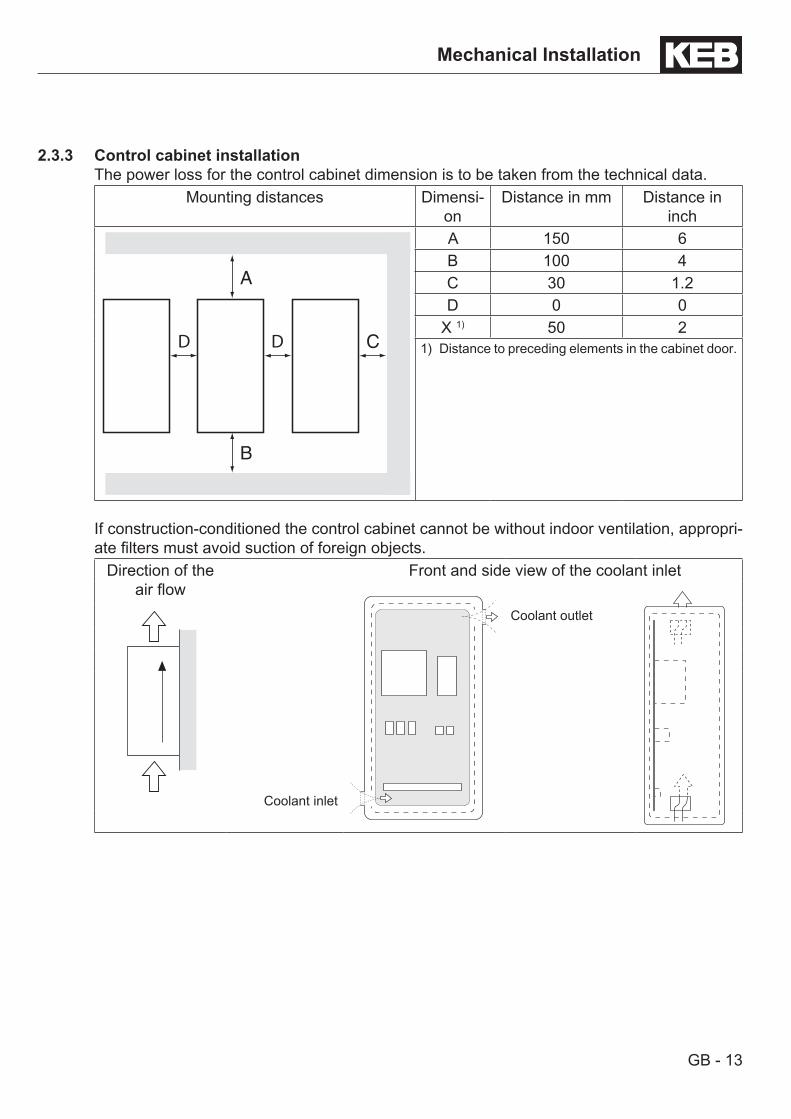
2.3.3 Control cabinet installationThe power loss for the control cabinet dimension is to be taken from the technical data.
Mounting distances Dimensi-on
Distance in mm Distance in inch
C
A
B
DD
A 150 6B 100 4C 30 1.2D 0 0
X 1) 50 21) Distance to preceding elements in the cabinet door.
If construction-conditioned the control cabinet cannot be without indoor ventilation, appropri-ate filters must avoid suction of foreign objects.
Direction of the air flow
Front and side view of the coolant inlet
Coolant outlet
Coolant inlet
GB - 14
Unit Description
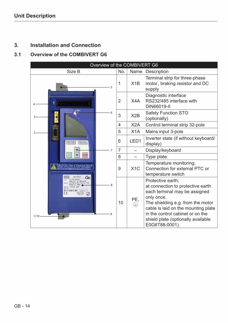
3. Installation and Connection3.1 Overview of the COMBIVERT G6
Overview of the COMBIVERT G6Size B No. Name Description
6
5
4
1/10
7
9
8
2
3
1 X1BTerminal strip for three-phase motor , braking resistor and DC supply
2 X4ADiagnostic interface RS232/485 interface with DIN66019-II
3 X2B Safety Function STO(optionally)
4 X2A Control terminal strip 32-pole5 X1A Mains input 3-pole
6 LED1 Inverter state (if without keyboard/display)
7 – Display/keyboard8 – Type plate
9 X1CTemperature monitoring;Connection for external PTC or temperature switch
10 PE,
Protective earth;at connection to protective earth each terminal may be assigned only once.The shielding e.g. from the motor cable is laid on the mounting plate in the control cabinet or on the shield plate (optionally available E0G6T88-0001).
GB - 15
Connection of the Power Unit
3.2 Connection of the power unit
Only Quali-fiedElectro-Personnel
All work from the transport, to installation and start-up as well as mainte-nance may only be done by qualified personnel (IEC 364 and/or CENELEC HD 384 and IEC-Report 664 and note national safety regulations). Accor-ding to this manual qualified staff means those who are able to recognise and judge the possible dangers based on their technical training and ex-perience and those with knowledge of the relevant standards and who are familiar with the field of power transmission.
Electric Shock
KEB COMBIVERT units contain dangerous voltages which can cause death or serious injury. The KEB COMBIVERT can be adjusted in such a way that energy regene-ration into the supply net is possible at regenerative operation also during mains power failure. Therefore a dangerous high tension can exist in the unit after switching off the supply system.Before working with the unit check the isolation from supply by mea-surements in the unit. Motors are to be secured against automatic starting.Care should be taken to ensure correct and safe operation to minimise risk to personnel and equipment.
The terminal strips meet the requirements on IEC 60947-7-1
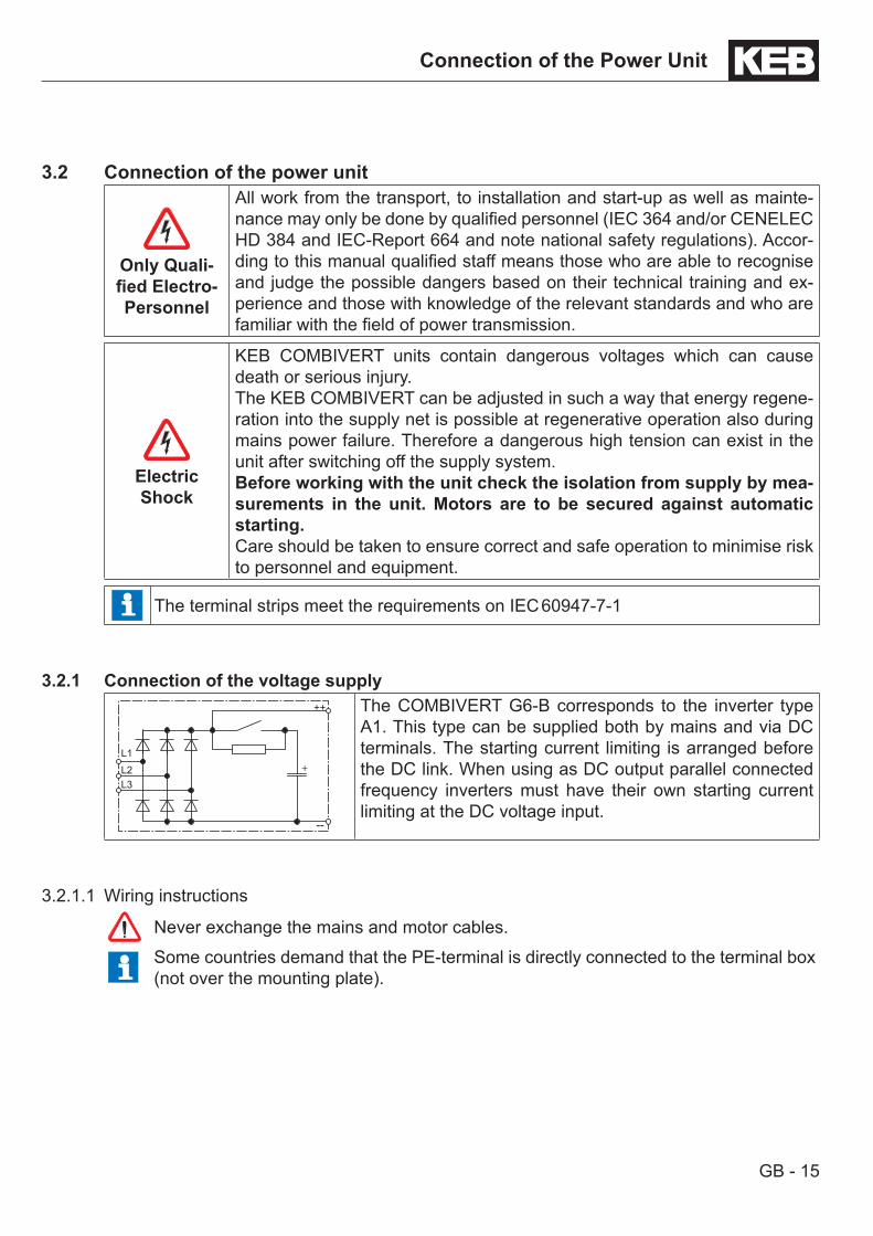
3.2.1 Connection of the voltage supply
+
++
--
L1L2L3
The COMBIVERT G6-B corresponds to the inverter type A1. This type can be supplied both by mains and via DC terminals. The starting current limiting is arranged before the DC link. When using as DC output parallel connected frequency inverters must have their own starting current limiting at the DC voltage input.
3.2.1.1 Wiring instructions
Never exchange the mains and motor cables.
Some countries demand that the PE-terminal is directly connected to the terminal box (not over the mounting plate).
GB - 16
Connection of the Power Unit
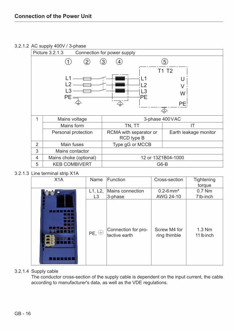
3.2.1.2 AC supply 400V / 3-phasePicture 3.2.1.3 Connection for power supply
L1L2L3PE
L1L2L3
UVW
PEPE
T1 T2
1 Mains voltage 3-phase 400 V ACMains form TN, TT IT
Personal protection RCMA with separator or RCD type B
Earth leakage monitor
2 Main fuses Type gG or MCCB3 Mains contactor4 Mains choke (optional) 12 or 13Z1B04-10005 KEB COMBIVERT G6-B
3.2.1.3 Line terminal strip X1AX1A Name Function Cross-section Tightening
torqueL1, L2,
L3Mains connection 3-phase
0.2-6 mm²AWG 24-10
0.7 Nm7 lb-inch
PE, Connection for pro-tective earth
Screw M4 for ring thimble
1.3 Nm11 lb inch
3.2.1.4 Supply cableThe conductor cross-section of the supply cable is dependent on the input current, the cable according to manufacturer's data, as well as the VDE regulations.
GB - 17
Connection of the Power Unit
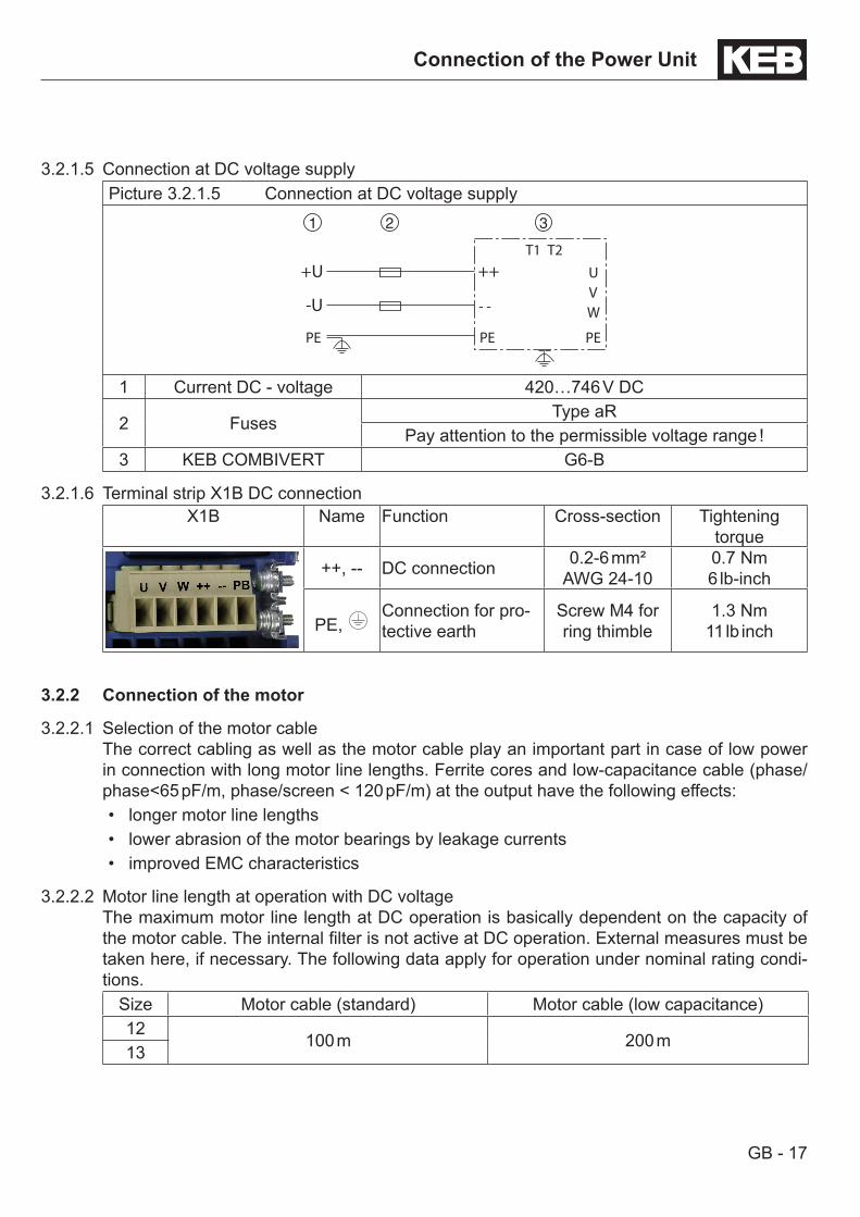
3.2.1.5 Connection at DC voltage supplyPicture 3.2.1.5 Connection at DC voltage supply
- -
UVW
PEPEPE
T1 T2
+++U
-U
1 Current DC - voltage 420…746 V DC
2 FusesType aR
Pay attention to the permissible voltage range !3 KEB COMBIVERT G6-B
3.2.1.6 Terminal strip X1B DC connectionX1B Name Function Cross-section Tightening
torque
++, -- DC connection 0.2-6 mm²AWG 24-10
0.7 Nm6 lb-inch
PE, Connection for pro-tective earth
Screw M4 for ring thimble
1.3 Nm11 lb inch
3.2.2 Connection of the motor
3.2.2.1 Selection of the motor cableThe correct cabling as well as the motor cable play an important part in case of low power in connection with long motor line lengths. Ferrite cores and low-capacitance cable (phase/phase<65 pF/m, phase/screen < 120 pF/m) at the output have the following effects:• longer motor line lengths• lower abrasion of the motor bearings by leakage currents• improved EMC characteristics
3.2.2.2 Motor line length at operation with DC voltageThe maximum motor line length at DC operation is basically dependent on the capacity of the motor cable. The internal filter is not active at DC operation. External measures must be taken here, if necessary. The following data apply for operation under nominal rating condi-tions.
Size Motor cable (standard) Motor cable (low capacitance)12
100 m 200 m13
GB - 18
Connection of the Power Unit
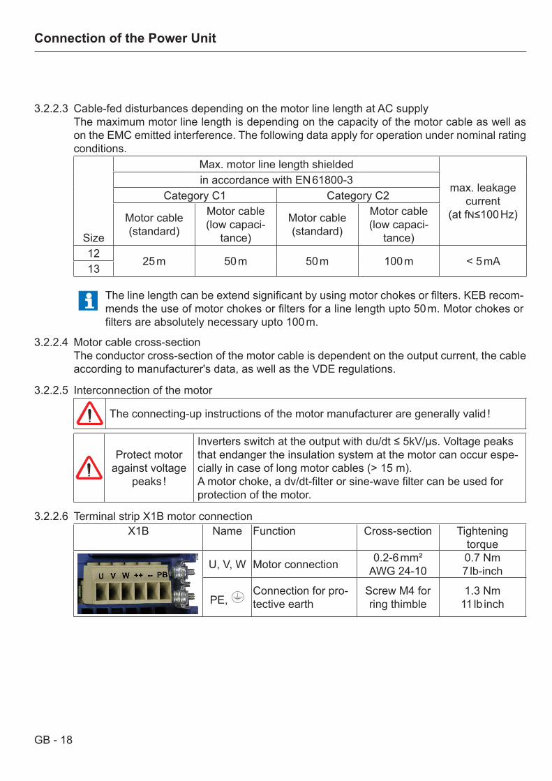
3.2.2.3 Cable-fed disturbances depending on the motor line length at AC supplyThe maximum motor line length is depending on the capacity of the motor cable as well as on the EMC emitted interference. The following data apply for operation under nominal rating conditions.
Size
Max. motor line length shielded
max. leakage current
(at fN≤100 Hz)
in accordance with EN 61800-3 Category C1 Category C2
Motor cable (standard)
Motor cable (low capaci-
tance)
Motor cable (standard)
Motor cable (low capaci-
tance)12
25 m 50 m 50 m 100 m < 5 mA13
The line length can be extend significant by using motor chokes or filters. KEB recom-mends the use of motor chokes or filters for a line length upto 50 m. Motor chokes or filters are absolutely necessary upto 100 m.
3.2.2.4 Motor cable cross-sectionThe conductor cross-section of the motor cable is dependent on the output current, the cable according to manufacturer's data, as well as the VDE regulations.
3.2.2.5 Interconnection of the motor
The connecting-up instructions of the motor manufacturer are generally valid !
Protect motor against voltage
peaks !
Inverters switch at the output with du/dt ≤ 5kV/µs. Voltage peaks that endanger the insulation system at the motor can occur espe-cially in case of long motor cables (> 15 m).A motor choke, a dv/dt-filter or sine-wave filter can be used for protection of the motor.
3.2.2.6 Terminal strip X1B motor connectionX1B Name Function Cross-section Tightening
torque
U, V, W Motor connection 0.2-6 mm²AWG 24-10
0.7 Nm7 lb-inch
PE, Connection for pro-tective earth
Screw M4 for ring thimble
1.3 Nm11 lb inch
GB - 19
Connection of the Power Unit
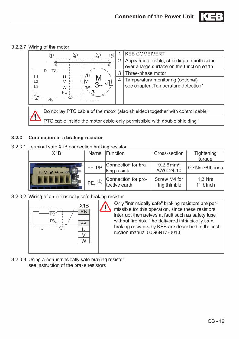
3.2.2.7 Wiring of the motor
L1L2L3
UVWPE
UVW
PEPE
T1 T2
1 KEB COMBIVERT2 Apply motor cable, shielding on both sides
over a large surface on the function earth3 Three-phase motor4 Temperature monitoring (optional)
see chapter „Temperature detection"
Do not lay PTC cable of the motor (also shielded) together with control cable !
PTC cable inside the motor cable only permissible with double shielding !
3.2.3 Connection of a braking resistor
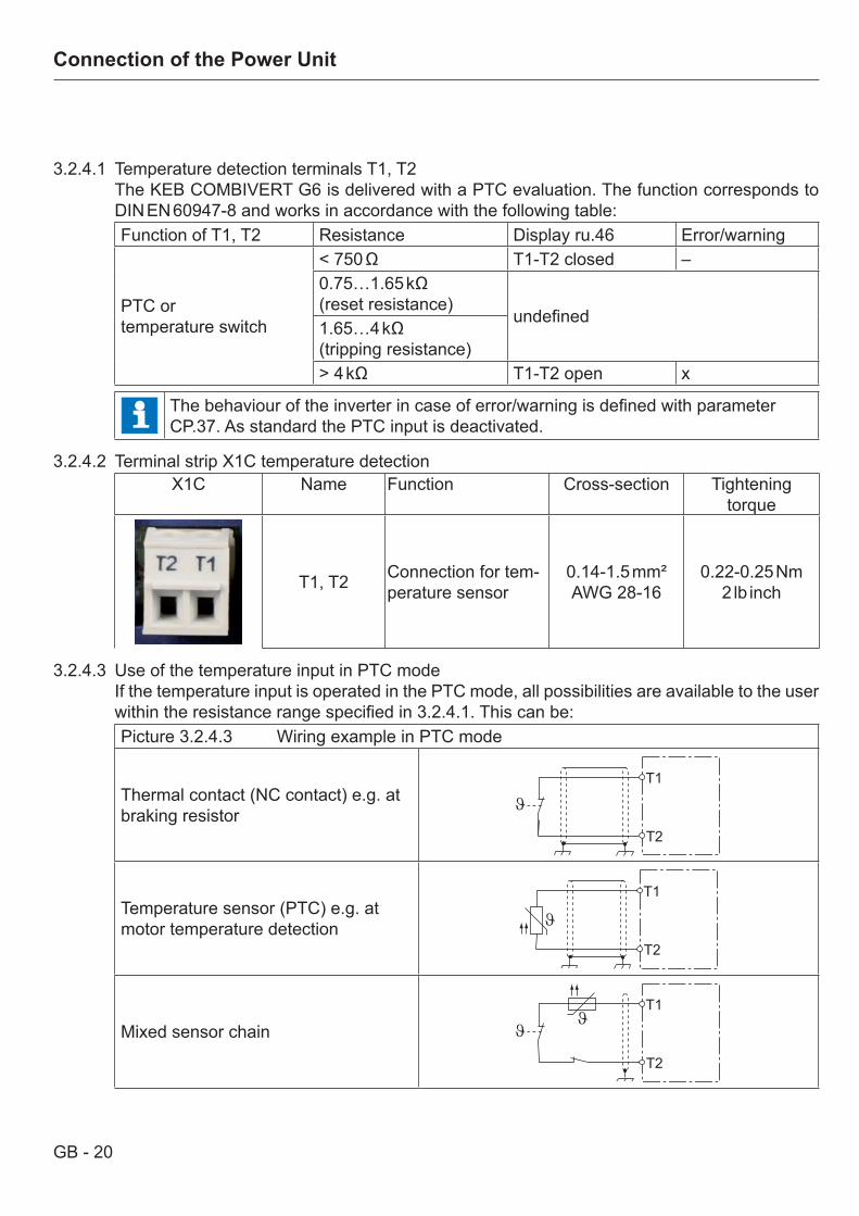
3.2.3.1 Terminal strip X1B connection braking resistorX1B Name Function Cross-section Tightening
torque
++, PB Connection for bra-king resistor
0.2-6 mm²AWG 24-10 0.7 Nm76 lb-inch
PE, Connection for pro-tective earth
Screw M4 for ring thimble
1.3 Nm11 lb inch
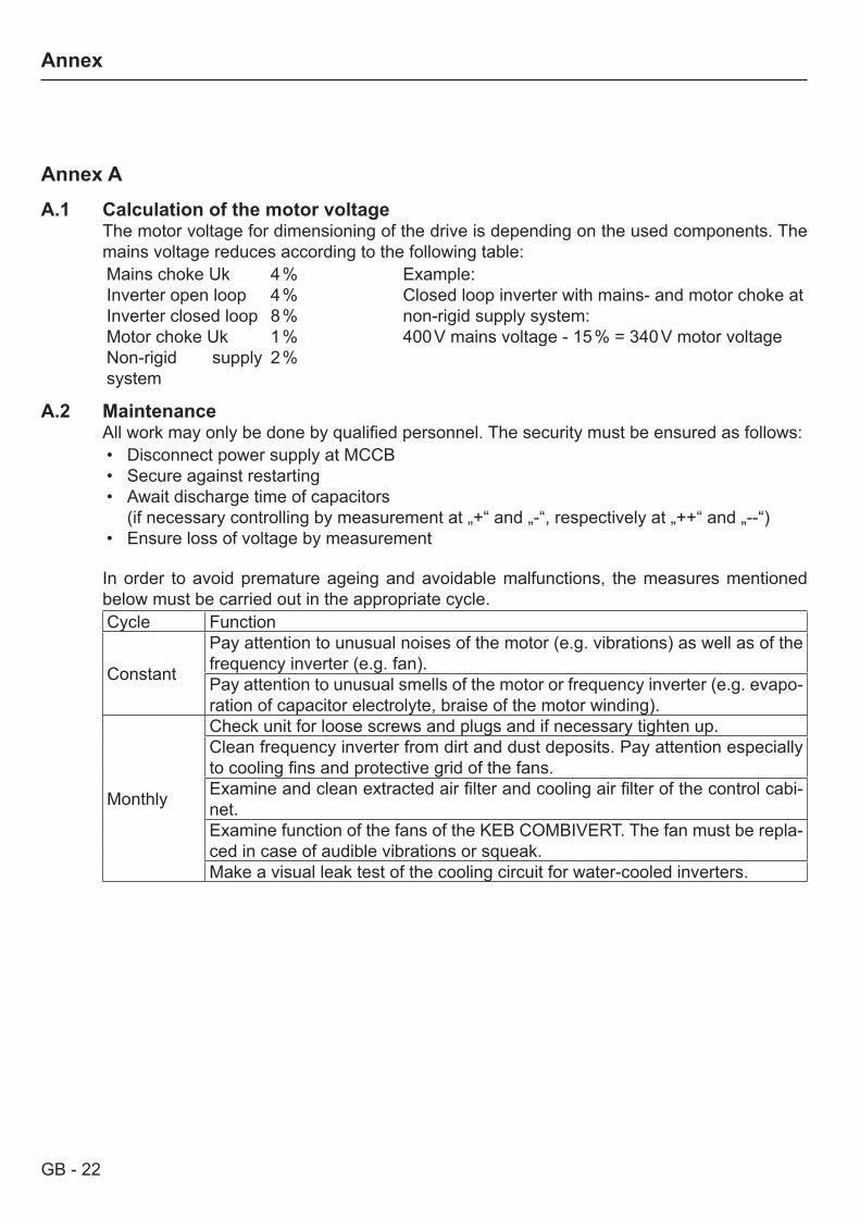
3.2.3.2 Wiring of an intrinsically safe braking resistor
X1BPB--++UVW
PBPA
Only "intrinsically safe" braking resistors are per-missible for this operation, since these resistors interrupt themselves at fault such as safety fuse without fire risk. The delivered intrinsically safe braking resistors by KEB are described in the inst-ruction manual 00G6N1Z-0010.
3.2.3.3 Using a non-intrinsically safe braking resistorsee instruction of the brake resistors
GB - 20
Connection of the Power Unit
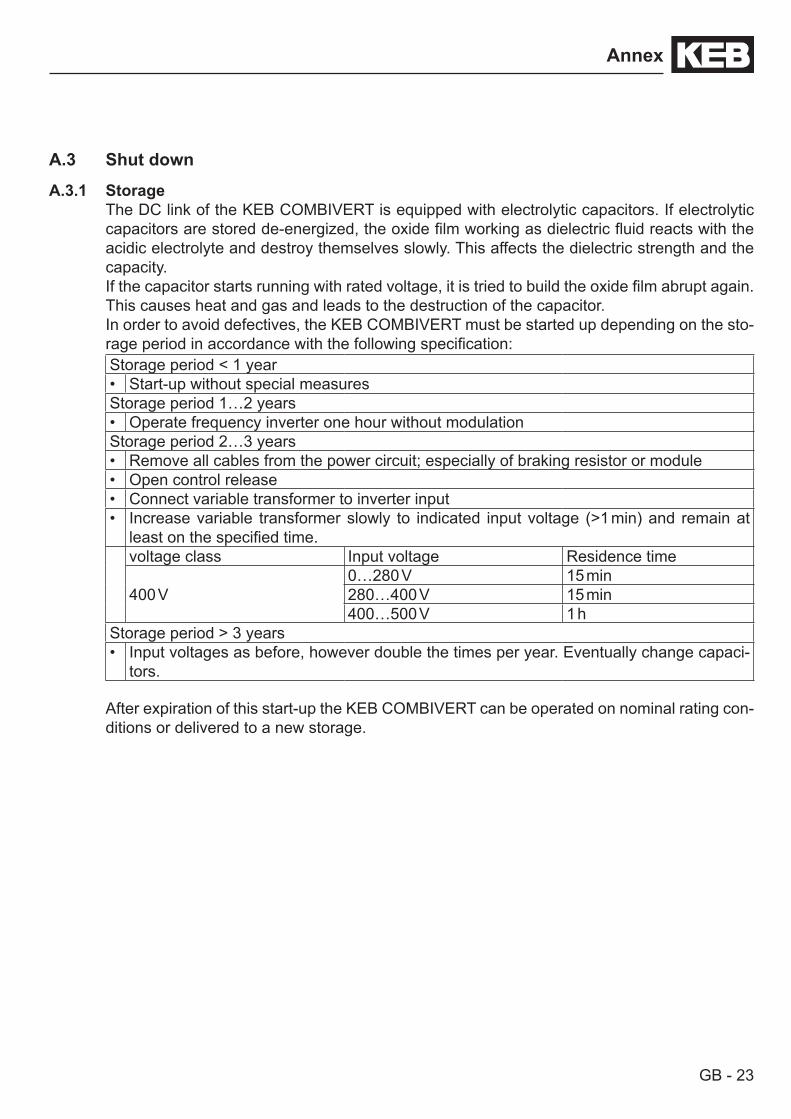
3.2.4.1 Temperature detection terminals T1, T2The KEB COMBIVERT G6 is delivered with a PTC evaluation. The function corresponds to DIN EN 60947-8 and works in accordance with the following table:Function of T1, T2 Resistance Display ru.46 Error/warning
PTC ortemperature switch
< 750 Ω T1-T2 closed –0.75…1.65 kΩ (reset resistance)
undefined1.65…4 kΩ (tripping resistance)> 4 kΩ T1-T2 open x
The behaviour of the inverter in case of error/warning is defined with parameter CP.37. As standard the PTC input is deactivated.
3.2.4.2 Terminal strip X1C temperature detectionX1C Name Function Cross-section Tightening
torque
T1, T2 Connection for tem-perature sensor
0.14-1.5 mm²AWG 28-16
0.22-0.25 Nm2 lb inch
3.2.4.3 Use of the temperature input in PTC modeIf the temperature input is operated in the PTC mode, all possibilities are available to the user within the resistance range specified in 3.2.4.1. This can be:Picture 3.2.4.3 Wiring example in PTC mode
Thermal contact (NC contact) e.g. at braking resistor
T1
T2
Temperature sensor (PTC) e.g. at motor temperature detection
T1
T2
Mixed sensor chainT1
T2

GB - 21
Connection of the Power Unit
3.2.5 Final test informations of the machines/systems which are provided with frequency inverters according to EN 60204 Part 1 of 2007
3.2.5.1 Voltage test (in accordance with EN60204-1 chapter 18.4)Testing with AC voltage may not be executed, since there is danger to the inverter. Because of the noise suppression capacitors also the generator would immediately release with current error.
Solution: According to EN60204 it is permissible to disconnect already tested components. KEB inver-ters are delivered ex works voltage tested to 100% according to product standard.
3.2.5.2 Isolation resistance measurement (in accordance with EN60204-1 chapter 18.3)An isolation resistance measurement with 500 Vdc is permissible, if all power unit connec-tions (grid-connected potential) and control connections are bridged with PE. At any unit it can be expected with an insulating resistance > 2 MΩ !
GB - 22
Annex
Annex AA.1 Calculation of the motor voltage
The motor voltage for dimensioning of the drive is depending on the used components. The mains voltage reduces according to the following table: Mains choke Uk 4 % Example:Inverter open loop 4 % Closed loop inverter with mains- and motor choke at
non-rigid supply system:400 V mains voltage - 15 % = 340 V motor voltage
Inverter closed loop 8 %Motor choke Uk 1 %Non-rigid supply system
2 %
A.2 MaintenanceAll work may only be done by qualified personnel. The security must be ensured as follows:• Disconnect power supply at MCCB• Secure against restarting• Await discharge time of capacitors
(if necessary controlling by measurement at „+“ and „-“, respectively at „++“ and „--“)• Ensure loss of voltage by measurement
In order to avoid premature ageing and avoidable malfunctions, the measures mentioned below must be carried out in the appropriate cycle.Cycle Function
Constant
Pay attention to unusual noises of the motor (e.g. vibrations) as well as of the frequency inverter (e.g. fan).Pay attention to unusual smells of the motor or frequency inverter (e.g. evapo-ration of capacitor electrolyte, braise of the motor winding).
Monthly
Check unit for loose screws and plugs and if necessary tighten up.Clean frequency inverter from dirt and dust deposits. Pay attention especially to cooling fins and protective grid of the fans.Examine and clean extracted air filter and cooling air filter of the control cabi-net.Examine function of the fans of the KEB COMBIVERT. The fan must be repla-ced in case of audible vibrations or squeak.Make a visual leak test of the cooling circuit for water-cooled inverters.
GB - 23
Annex
A.3 Shut down
A.3.1 StorageThe DC link of the KEB COMBIVERT is equipped with electrolytic capacitors. If electrolytic capacitors are stored de-energized, the oxide film working as dielectric fluid reacts with the acidic electrolyte and destroy themselves slowly. This affects the dielectric strength and the capacity. If the capacitor starts running with rated voltage, it is tried to build the oxide film abrupt again. This causes heat and gas and leads to the destruction of the capacitor.In order to avoid defectives, the KEB COMBIVERT must be started up depending on the sto-rage period in accordance with the following specification:Storage period < 1 year• Start-up without special measuresStorage period 1…2 years• Operate frequency inverter one hour without modulationStorage period 2…3 years• Remove all cables from the power circuit; especially of braking resistor or module• Open control release• Connect variable transformer to inverter input• Increase variable transformer slowly to indicated input voltage (>1 min) and remain at
least on the specified time.voltage class Input voltage Residence time
400 V0…280 V 15 min280…400 V 15 min400…500 V 1 h
Storage period > 3 years• Input voltages as before, however double the times per year. Eventually change capaci-
tors. After expiration of this start-up the KEB COMBIVERT can be operated on nominal rating con-ditions or delivered to a new storage.
GB - 24
Annex
Annex BB.1 Certification
B.1.1 CE-MarkingCE marked frequency inverters and servo drives were developed and manufactured to comply with the regulations of the Low-Voltage Directive 2006/95/EC and EMC directive (2004/108/EC). The harmonized standards of the series EN 61800-5-1, EN 61800-5-2 and EN 61800-3 were used.This is a product of limited availability in accordance with EN 61800-3. This product may cause radio interference in residential areas. In this case the operator may need to take cor-responding measures.The inverter or servo drive must not be started until it is determined that the installation com-plies with the Machine directive (2006/42/EC) as well as the EMC-directive (2004/108/EC)(note EN 60204).
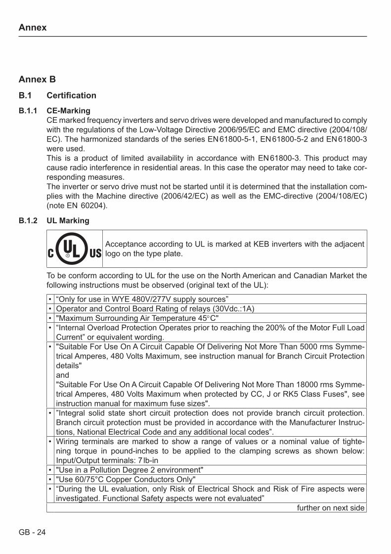
B.1.2 UL Marking
Acceptance according to UL is marked at KEB inverters with the adjacent logo on the type plate.
To be conform according to UL for the use on the North American and Canadian Market the following instructions must be observed (original text of the UL):
• “Only for use in WYE 480V/277V supply sources”• Operator and Control Board Rating of relays (30Vdc.:1A)• "Maximum Surrounding Air Temperature 45°C"• “Internal Overload Protection Operates prior to reaching the 200% of the Motor Full Load
Current” or equivalent wording.• "Suitable For Use On A Circuit Capable Of Delivering Not More Than 5000 rms Symme-
trical Amperes, 480 Volts Maximum, see instruction manual for Branch Circuit Protection details"and"Suitable For Use On A Circuit Capable Of Delivering Not More Than 18000 rms Symme-trical Amperes, 480 Volts Maximum when protected by CC, J or RK5 Class Fuses", see instruction manual for maximum fuse sizes".
• ”Integral solid state short circuit protection does not provide branch circuit protection. Branch circuit protection must be provided in accordance with the Manufacturer Instruc-tions, National Electrical Code and any additional local codes”.
• Wiring terminals are marked to show a range of values or a nominal value of tighte-ning torque in pound-inches to be applied to the clamping screws as shown below: Input/Output terminals: 7 lb-in
• "Use in a Pollution Degree 2 environment"• "Use 60/75°C Copper Conductors Only"• “During the UL evaluation, only Risk of Electrical Shock and Risk of Fire aspects were
investigated. Functional Safety aspects were not evaluated”further on next side
GB - 25
Annex
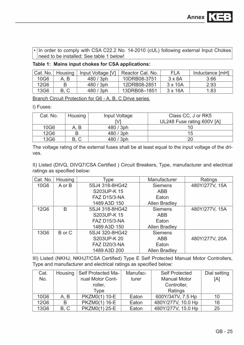
• In order to comply with CSA C22.2 No. 14-2010 (cUL) following external Input Chokes need to be installed: See table 1 below!
Table 1: Mains input chokes for CSA applications:
Cat. No. Housing Input Voltage [V] Reactor Cat. No. FLA Inductance [mH]10G6 A, B 480 / 3ph 10DRB08-3751 3 x 8A 3.6612G6 B 480 / 3ph 12DRB08-2851 3 x 10A 2.9313G6 B, C 480 / 3ph 13DRB08–1851 3 x 16A 1.83
Branch Circuit Protection for G6 - A, B, C Drive series
I) Fuses:
Cat. No. Housing Input Voltage[V]
Class CC, J or RK5UL248 Fuse rating 600V [A]
10G6 A, B 480 / 3ph 1012G6 B 480 / 3ph 1513G6 B, C 480 / 3ph 20
The voltage rating of the external fuses shall be at least equal to the input voltage of the dri-ves.
II) Listed (DIVQ, DIVQ7/CSA Certified ) Circuit Breakers, Type, manufacturer and electrical ratings as specified below:
Cat. No. Housing Type Manufacturer Ratings10G6 A or B 5SJ4 318-8HG42
S203UP-K 15FAZ D15/3-NA1489 A3D 150
Siemens ABB
EatonAllen Bradley
480Y/277V, 15A
12G6 B 5SJ4 318-8HG42S203UP-K 15FAZ D15/3-NA1489 A3D 150
Siemens ABB
EatonAllen Bradley
480Y/277V, 15A
13G6 B or C 5SJ4 320-8HG42S203UP-K 20FAZ D20/3-NA1489 A3D 200
Siemens ABB
EatonAllen Bradley
480Y/277V, 20A
III) Listed (NKHJ, NKHJ7/CSA Certified) Type E Self Protected Manual Motor Controllers, Type and manufacturer and electrical ratings as specified below:
Cat.No.
Housing Self Protected Ma-nual Motor Cont-
roller, Type
Manufac-turer
Self Protected Manual Motor
Controller, Ratings
Dial setting[A]
10G6 A, B PKZM0(1) 10-E Eaton 600Y/347V, 7.5 Hp 1012G6 B PKZM0(1) 16-E Eaton 480Y/277V, 10.0 Hp 1613G6 B, C PKZM0(1) 25-E Eaton 480Y/277V, 15.0 Hp 25
GB - 26
Annex
B.2 Further informations and documentationYou find supplementary manuals and instructions for the download under
http://www.keb.de > Service & Downloads > Downloads
General instructions• EMC and safety instructions• Manuals for further control boards
Service notes• Download of parameter lists• error messages
Instruction and information for construction and development• Preparation of a user-defined parameter menu• Programming of the digital inputs• Input fuses in accordance with UL • Application manual (access for registered customers)• Motor configurator to select the appropriate inverter and to create downloads for parame-
terizing the inverter.
Approvals and approbations• Declaration of conformity CE
Others• COMBIVIS, the software for comfortable parameterization of the inverters via PC (available
per download or as DVD)

Revision history:Revision Date DescriptionRev.1B 2011-03 First published versionRev.1C 2011-09 „Original manual“ included; part code extended; technical data changed; connection braking re-
sistor changedRev.1D 2012-02 recommended supply and motor cable cross-section removed; drawings power and motor con-
nection changed; UL certification; addresses back

KEB Antriebstechnik Austria GmbHRitzstraße 8 • A-4614 Marchtrenk
fon: +43 7243 53586-0 • fax: +43 7243 53586-21net: www.keb.at • mail: [email protected]
KEB AntriebstechnikHerenveld 2 • B-9500 Geraadsbergen
fon: +32 5443 7860 • fax: +32 5443 7898mail: [email protected]
KEB Power Transmission Technology (Shanghai) Co.,Ltd.No. 435 Qianpu Road, Chedun Town, Songjiang District,
CHN-Shanghai 201611, P.R. Chinafon: +86 21 37746688 • fax: +86 21 37746600
net: www.keb.cn • mail: [email protected]
KEB Antriebstechnik Austria GmbHOrganizační složka
K. Weise 1675/5 • CZ-370 04 České Budějovicefon: +420 387 699 111 • fax: +420 387 699 119net: www.keb.cz • mail: [email protected]
KEB Antriebstechnik GmbHWildbacher Str. 5 • D–08289 Schneeberg
fon: +49 3772 67-0 • fax: +49 3772 67-281mail: [email protected]
KEB EspañaC/ Mitjer, Nave 8 - Pol. Ind. LA MASIA
E-08798 Sant Cugat Sesgarrigues (Barcelona)fon: +34 93 897 0268 • fax: +34 93 899 2035
mail: [email protected]
Société Française KEBZ.I. de la Croix St. Nicolas • 14, rue Gustave Eiffel
F-94510 LA QUEUE EN BRIEfon: +33 1 49620101 • fax: +33 1 45767495
net: www.keb.fr • mail: [email protected]
KEB (UK) Ltd.6 Chieftain Buisiness Park, Morris Close
Park Farm, Wellingborough GB-Northants, NN8 6 XFfon: +44 1933 402220 • fax: +44 1933 400724
net: www.keb-uk.co.uk • mail: [email protected]
KEB Italia S.r.l.Via Newton, 2 • I-20019 Settimo Milanese (Milano)
fon: +39 02 33535311 • fax: +39 02 33500790net: www.keb.it • mail: [email protected]
KEB Japan Ltd.15–16, 2–Chome, Takanawa Minato-ku
J–Tokyo 108-0074fon: +81 33 445-8515 • fax: +81 33 445-8215
mail: [email protected]
KEB Korea SeoulRoom 1709, 415 Missy 2000
725 Su Seo Dong, Gang Nam GuROK-135-757 Seoul/South Korea
fon: +82 2 6253 6771 • fax: +82 2 6253 6770mail: [email protected]
KEB RUS Ltd.Lesnaya Str. House 30, Dzerzhinsky (MO)
RUS-140091 Moscow regionfon: +7 495 550 8367 • fax: +7 495 632 0217
net: www.keb.ru • mail: [email protected]
KEB SverigeBox 265 (Bergavägen 19)
S-43093 Hälsöfon: +46 31 961520 • fax: +46 31 961124
mail: [email protected]
KEB America, Inc.5100 Valley Industrial Blvd. South
USA-Shakopee, MN 55379fon: +1 952 224-1400 • fax: +1 952 224-1499
net: www.kebamerica.com • mail: [email protected]
© KEBMat.No. 00G6NEL-0B00
Rev. 1DDate 02/2012
More and newest addresses at http://www.keb.de
Karl E. Brinkmann GmbHFörsterweg 36-38 • D-32683 Barntrup
fon: +49 5263 401-0 • fax: +49 5263 401-116net: www.keb.de • mail: [email protected]
KEB worldwide…


![a fu titel gb - Electrónica Indústrialelectronicaindustrial.pt/application/uploads/files/00f5bemka02[1].pdf · 2 This manual describes the KEB COMBIVERT F5. Particular attention](https://img.pdfslide.us/doc/110x75/5b4310417f8b9ab15f8baa97/a-fu-titel-gb-electronica-industriale-1pdf-2-this-manual-describes-the.jpg)