Embed Size (px)
Citation preview
USA
C O M B I V E R T
03/2004
00.F
5.0U
M-K
B01
Installation Guide & Operation ManualB-Housing1 - 3 hp 230 V1/2 - 5 hp 460 V
B ControlC ControlG Control
This manual describes the KEB COMBIVERT F5 series motor control. This manual focusesattention on installation, connection as well as basic operation. Due to the various applicationpossibilities and extensive programming capabilities with this unit, it was necessary to provideseparet documentation which contains all of this detailed information. Please visit our Website www.kebco.com or contact your local sales office. A list of addtional manuals is providedat the end of this book.
The icons below are used to draw draw attention to the reader. They have the followingmeanings:
Danger!Warning!Caution!
Attention!Observe atall costs!
InformationHintTip
3
Table of Contents1. Saftey and Operating Instructions ......................................... ..5
2. Product Description................................................................. ..6
2.1 Application ...................................................................................... ..6
2.2 Part number identification .............................................................. ..6
2.3 Technical Data ................................................................................ ..72.3.1 230 V-class ........................................................................................ ..72.3.2 460 V-class ........................................................................................ ..8
2.4 Dimensions and terminals .............................................................. ..9
3. Installation and Connection.................................................. ..10
3.1 Control Cabinet Installation .......................................................... ..10
3.2 Good EMC Installation Techniques .............................................. ..11
3.3 Connection of Power Circuit ......................................................... ..123.3.1 Terminalstrip X1A ............................................................................ ..123.3.2 Wiring instructions ........................................................................... ..123.3.3 Line connection ............................................................................... ..133.3.4 Motor connection ............................................................................. ..143.3.5 Motor Overload Protection .............................................................. ..143.3.6 Connection of the braking resistor ................................................. ..153.4.1 Terminal Strip Connections ............................................................. ..16
3.4 Control Circuit: F5-GENERAL/ F5-COMPACT ........................... ..163.4.2 Connection of the control signals .................................................... ..173.4.3 Digital Inputs .................................................................................... ..173.4.4 Analog Inputs .................................................................................. ..173.4.5 Voltage Input / External Power Supply ............................................ ..183.4.6 Digital Outputs ................................................................................. ..183.4.7 Relay Outputs .................................................................................. ..183.4.8 Analog Outputs ............................................................................... ..183.4.9 Voltage Output ................................................................................. ..18
Contents
4
Contents
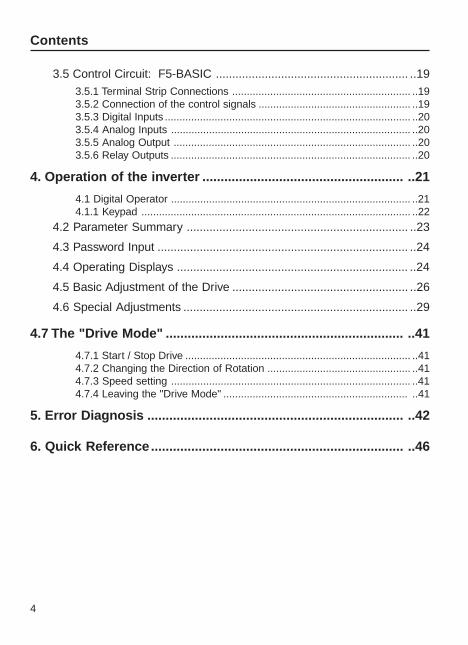
3.5 Control Circuit: F5-BASIC ........................................................... ..193.5.1 Terminal Strip Connections ............................................................. ..193.5.2 Connection of the control signals .................................................... ..193.5.3 Digital Inputs .................................................................................... ..203.5.4 Analog Inputs .................................................................................. ..203.5.5 Analog Output ................................................................................. ..203.5.6 Relay Outputs .................................................................................. ..20
4. Operation of the inverter ....................................................... ..21
4.1 Digital Operator .................................................................................. ..214.1.1 Keypad ............................................................................................ ..22
4.2 Parameter Summary .................................................................... ..23
4.3 Password Input ............................................................................. ..24
4.4 Operating Displays ....................................................................... ..24
4.5 Basic Adjustment of the Drive ...................................................... ..26
4.6 Special Adjustments ..................................................................... ..29
4.7 The "Drive Mode" ................................................................. ..41
4.7.1 Start / Stop Drive ............................................................................. ..414.7.2 Changing the Direction of Rotation ................................................. ..414.7.3 Speed setting .................................................................................. ..414.7.4 Leaving the "Drive Mode" ............................................................... ..41
5. Error Diagnosis ...................................................................... ..42
6. Quick Reference..................................................................... ..46
5
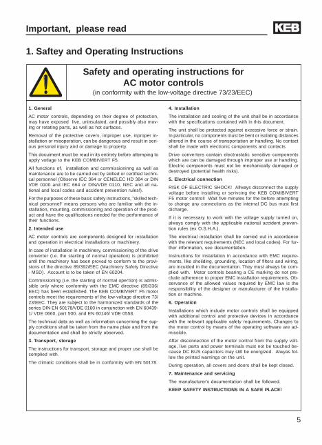
1. General
AC motor controls, depending on their degree of protection,may have exposed live, uninsulated, and possibly also mov-ing or rotating parts, as well as hot surfaces.
Removal of the protective covers, improper use, inproper in-stallation or misoperation, can be dangerous and result in seri-ous personal injury and or damage to property.
This docuiment must be read in its entirety before attemping toapply votlage to the KEB COMBIVERT F5.
All functions of, installation and commissioninng as well asmaintenance are to be carried out by skilled or certified techni-cal personnel (Observe IEC 364 or CENELEC HD 384 or DINVDE 0100 and IEC 664 or DIN/VDE 0110, NEC and all na-tional and local codes and accident prevention rules!).
For the purposes of these basic safety instructions, ”skilled tech-nical personnel“ means persons who are familiar with the in-stallation, mounting, commissioning and operation of the prod-uct and have the qualifications needed for the performance oftheir functions.
2. Intended use
AC motor controls are components designed for installationand operation in electrical installations or machinery.
In case of installation in machinery, commissioning of the driveconverter (i.e. the starting of normal operation) is prohibiteduntil the machinery has been proved to conform to the provi-sions of the directive 89/392/EEC (Machinery Safety Directive- MSD). Account is to be taken of EN 60204.
Commissioning (i.e. the starting of normal opertion) is admis-sible only where conformity with the EMC directive (89/336/EEC) has been established. The KEB COMBIVERT F5 motorcontrols meet the requirements of the low-voltage directive 73/23/EEC. They are subject to the harmonized standards of theseries DIN EN 50178/VDE 0160 in conjunction with EN 60439-1/ VDE 0660, part 500, and EN 60146/ VDE 0558.
The technical data as well as information concerning the sup-ply conditions shall be taken from the name plate and from thedocumentation and shall be strictly observed.
3. Transport, storage
The instructions for transport, storage and proper use shall becomplied with.
The climatic conditions shall be in conformity with EN 50178.
Safety and operating instructions forAC motor controls
(in conformity with the low-voltage directive 73/23/EEC)
Important, please read
1. Saftey and Operating Instructions
4. Installation
The installation and cooling of the unit shall be in accordancewith the specifications contained with in this document.
The unit shall be protected against excessive force or strain.In particular, no components must be bent or isolating distancesaltered in the course of transportation or handling. No contactshall be made with electronic components and contacts.
Drive converters contain electrostatic sensitive componentswhich are can be damaged through improper use or handling.Electric components must not be mechanically damaged ordestroyed (potential health risks).
5. Electrical connection
RISK OF ELECTRIC SHOCK! Allways disconnect the supplyvoltage before installing or serivcing the KEB COMIBIVERTF5 motor control! Wait five minutes for the before attemptingto change any connections as the internal DC bus must firstdicharge.
If it is necessary to work with the voltage supply turned on,always comply with the applicable national accident preven-tion rules (ex O.S.H.A.).
The electrical installation shall be carried out in accordancewith the relevant requirements (NEC and local codes). For fur-ther information, see documentation.
Instructions for installation in accordance with EMC require-ments, like sheilding, grounding, location of filters and wiring,are inculded in the documentation. They must always be com-plied with. Motor controls bearing a CE marking do not pre-clude adherence to proper EMC installation requirements. Ob-servance of the allowed values required by EMC law is theresponsibility of the designer or manufacturer of the installa-tion or machine.
6. Operation
Installations which include motor controls shall be equippedwith additional control and protective devices in accordancewith the relevant applicable safety requirements. Changes tothe motor control by means of the operating software are ad-missible.
After disconnection of the motor control from the supply volt-age, live parts and power terminals must not be touched be-cause DC BUS capacitors may still be energized. Alwyas fol-low the printed warnings on the unit.
During operation, all covers and doors shall be kept closed.
7. Maintenance and servicing
The manufacturer’s documentation shall be followed.
KEEP SAFETY INSTRUCTIONS IN A SAFE PLACE!
6
Product Description
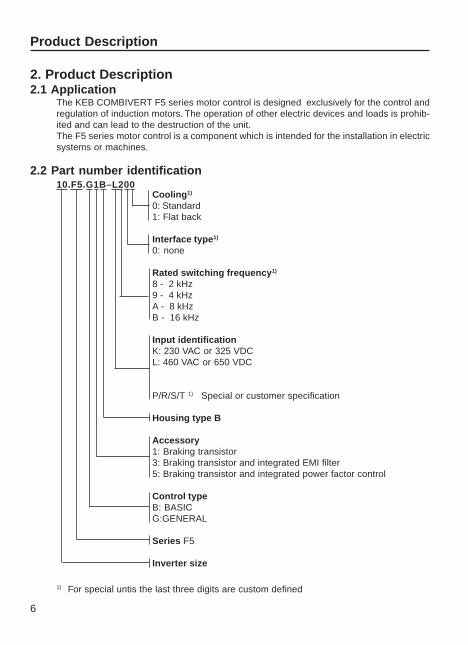
Cooling1)
0: Standard1: Flat back
Interface type1)
0: none
Rated switching frequency1)
8 - 2 kHz9 - 4 kHzA - 8 kHzB - 16 kHz
Input identificationK: 230 VAC or 325 VDCL: 460 VAC or 650 VDC
P/R/S/T 1) Special or customer specification
Housing type B
Accessory1: Braking transistor3: Braking transistor and integrated EMI filter5: Braking transistor and integrated power factor control
Control typeB: BASICG:GENERAL
Series F5
Inverter size
2. Product Description2.1 Application
The KEB COMBIVERT F5 series motor control is designed exclusively for the control andregulation of induction motors. The operation of other electric devices and loads is prohib-ited and can lead to the destruction of the unit.The F5 series motor control is a component which is intended for the installation in electricsystems or machines.
2.2 Part number identification10.F5.G1B–L200
1) For special untis the last three digits are custom defined
7
Product Description
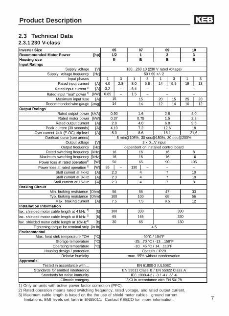
2.3 Technical Data2.3.1 230 V-class
1) Only on units with active power factor correction (PFC).2) Rated operation means rated switching frequency, rated voltage, and rated output current.3) Maximum cable length is based on the the use of shield motor cables, ground current
limitations, EMI levels set forth in EN55011. Contact KEBCO for more information.
Inverter Size 05 07 09 10Recommended Motor Power [hp] 1/2 1 2 3Housing size B B BInput Ratings
Supply voltage [V] 180...260 ±0 (230 V rated voltage)Supply voltage frequency [Hz] 50 / 60 +/- 2
Input phases 1 3 1 3 1 3 1 3Rated input current [A] 4,0 2,8 8,0 5,6 14 9,5 19 13
Rated input current 1) [A] 3,2 – 6,4 – – –
Rated input "real" power 1) [kW] 0.85 – 1.5 – – –Maximum input fuse [A] 15 20 15 25 20
Recommended wire gauge [awg] 14 12 14 10 12Output Ratings
Rated output power [kVA] 0,90 1.6 2.8 4.0Rated motor power [kW] 0.37 0.75 1,5 2,2
Rated output current [A] 2.0 4.0 6.8 9.6Peak current (30 seconds) [A] 4,10 7.2 12,6 18
Over current fault (E.OC) trip level [A] 5.0 8.6 15,1 21,6Overload curve (see annex) 5 min@105%, 30 sec@150%, 30 sec@200%
Output voltage [V] 3 x 0...V inputOutput frequency [Hz] dependent on installed control board
Rated switching frequency [kHz] 16 16 16 8Maximum switching frequency [kHz] 16 16 16 16
Power loss at rated operation2) [W] 50 65 90 105
Power loss at rated operation 1) [W] 85 – 130 – – –Stall current at 4kHz [A] 2.3 4 7 10Stall current at 8kHz [A] 2.3 4 7 10
Stall current at 16kHz [A] 2.3 4 7 8Braking Circuit
Min. braking resistance [Ohm] 56 56 47 33Typ. braking resistance [Ohm] 100 100 68 56
Max. braking current [A] 7.5 7.5 9.5 12Installation Information
Max. shielded motor cable length at 4 kHz 3) [ft] 100 330 330
Max. shielded motor cable length at 8 kHz 3) [ft] 65 165 330
Max. shielded motor cable length at 16kHz3) [ft] 30 65 130Tightening torque for terminal strip [in lb] 4.5
EnvironmentalMax. heat sink temperature TOH [°C] 90°C / 194°F
Storage temperature [°C] -25...70 °C / -13…158°FOperating temperature [°C] -10...45 °C / 14…113°F
Housing design / protection Chassis / IP20Relative humidity max. 95% without condensation
ApprovalsTested in accordance with… EN 61800-3 /UL508C
Standards for emitted interference EN 55011 Class B / EN 55022 Class AStandards for noise immunity IEC 1000-4-2 / -3 / -4 / -5/ -6
Climatic category 3K3 in accordance with EN 50178
B
1514
8
Product Description
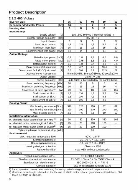
2.3.2 460 V-class
1) Rated operation means rated switching frequency, rated voltage, and rated output current.2) Maximum cable length is based on the the use of shield motor cables, ground current limitations, EMI
levels set forth in EN55011.
Inverter Size 05 07 09 10 12Recommended Motor Power [hp] 1/2 1 2 3 5Housing size B B B B BInput Ratings
Supply voltage [V] 305...500 ±0 (460 V nominal voltage )Supply voltage frequency [Hz] 50 / 60 +/- 2
Input phases 3 3 3 3 3Rated input current [A] 1,4 2,5 4,8 6,7 11
Maximum input fuse [A] 15 15 15 15 20Recommended wire gauge [awg] 14 14 14 14 12
Output RatingsRated output power [kVA] 0,9 1.8 2,8 4.0 6.6Rated motor power [kW] 0,37 0.75 1,5 2,2 4.0
Rated output current [A] 1.0 1.8 3.4 4.8 7.6Peak current (30 seconds) [A] 2.3 4.7 7.4 10.4 17
Over current fault (E.OC) trip level [A] 2.8 5.6 8.9 12.5 21Overload curve (see annex) 5 min@105%, 30 sec@150%, 30 sec@200%
Output voltage [V] 3 x 0…V LineOutput frequency [Hz] up to 1600Hz but limited by the control board
Rated switching frequency [kHz] 16 16 8 8 4Maximum switching frequency [kHz] 16 16 16 16 4
Power loss at rated operation1) [W] 60 90 80 120 150Stall current at 4kHz [A] 1,3 2,6 4,1 5,8 7,6Stall current at 8kHz [A] 1,3 2,6 4,1 5,8 –
Stall current at 16kHz [A] 1,3 2,6 3,5 4,9 –Braking Circuit
Min. braking resistance [Ohm] 390 120 120 82 82Typ. braking resistance [Ohm] 390 390 270 270 150
Max. braking current [A] 2.2 7.5 7.5 10 10Installation Information
ax. shielded motor cable length at 4 kHz 2) [ft] 30 30 330 330 165
ax. shielded motor cable length at 8 kHz 2) [ft] 25 25 100 165 –
ax. shielded motor cable length at 16kHz2) [ft] 15 20 100 100 –Tightening torque for terminal strip [in lb]
EnvironmentalMax. heat sink temperature TOH 90°C / 194°F
Storage temperature -25...70 °C / -13…158°FOperating temperature -10...45 °C / 14…113°F
Housing design / protection Chassis / IP20Relative humidity max. 95% without condensation
ApprovalsTested in accordance with… EN 61800-3 /UL508C
Standards for emitted interference EN 55011 Class B / EN 55022 Class AStandards for noise immunity IEC 1000-4-2 / -3 / -4 / -5/ -6
Climatic category 3K3 in accordance with EN 50178
4.5
9
Product Description
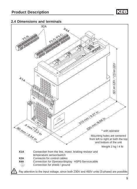
2.4 Dimensions and terminals
Pay attention to the input voltage, since both 230V and 460V units (3-phase) are possible.
!
"!
#$%&'
%$'(
("$
%)'(*
(($
%)'++
"#,
%+
'()
%-"*&,
%
+')&
./
.0%.
(!
X1A Connection from the line, motor, braking resistor andtemperature sensor/switch
X2A Connectin for control cablesX4A Connection for Operator/display HSP5-Servicecable
Connection for shield / ground
Weight 2 kg / 4 lb
Mounting holes are centeredfrom left to right at both the top
and bottom of the unit
* with operator
10
Installation and Connection
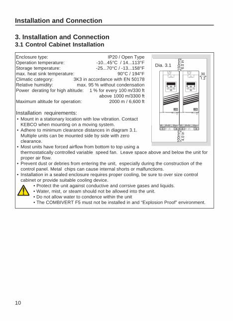
3. Installation and Connection3.1 Control Cabinet Installation
Enclosure type: IP20 / Open TypeOperation temperature: -10...45°C / 14...113°FStorage temperature: -25...70°C / -13...158°Fmax. heat sink temperature: 90°C / 194°FClimatic category: 3K3 in accordance with EN 50178Relative humidity: max. 95 % without condensationPower derating for high altitude: 1 % for every 100 m/330 ft
above 1000 m/3300 ftMaximum altitude for operation: 2000 m / 6,600 ft
Installation requirements:• Mount in a stationary location with low vibration. Contact
KEBCO when mounting on a moving system.• Adhere to minimum clearance distances in diagram 3.1.
Multiple units can be mounted side by side with zeroclearance.
• Most units have forced airflow from bottom to top using athermostatically controlled variable speed fan. Leave space above and below the unit forproper air flow.
• Prevent dust or debries from entering the unit, especially during the construction of thecontrol panel. Metal chips can cause internal shorts or malfunctions.
• Installation in a sealed enclosure requires proper cooling, be sure to over size controlcabinet or provide suitable cooling device.
• Protect the unit against conductive and corrsive gases and liquids.• Water, mist, or steam should not be allowed into the unit.• Do not allow water to condence within the unit• The COMBIVERT F5 must not be installed in and “Explosion Proof” environment.
ANTRIEBSTECHNIK
ANTRIEBSTECHNIK
Dia. 3.1
11
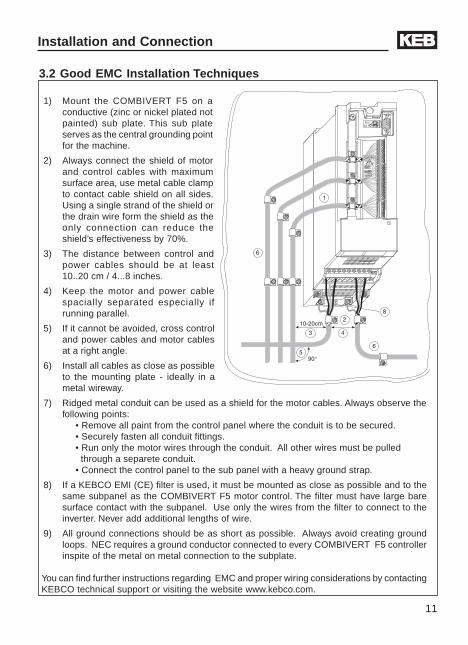
3.2 Good EMC Installation Techniques
1) Mount the COMBIVERT F5 on aconductive (zinc or nickel plated notpainted) sub plate. This sub plateserves as the central grounding pointfor the machine.
2) Always connect the shield of motorand control cables with maximumsurface area, use metal cable clampto contact cable shield on all sides.Using a single strand of the shield orthe drain wire form the shield as theonly connection can reduce theshield’s effectiveness by 70%.
3) The distance between control andpower cables should be at least10..20 cm / 4...8 inches.
4) Keep the motor and power cablespacially separated especially ifrunning parallel.
5) If it cannot be avoided, cross controland power cables and motor cablesat a right angle.
6) Install all cables as close as possibleto the mounting plate - ideally in ametal wireway.
7) Ridged metal conduit can be used as a shield for the motor cables. Always observe thefollowing points:
• Remove all paint from the control panel where the conduit is to be secured.• Securely fasten all conduit fittings.• Run only the motor wires through the conduit. All other wires must be pulled through a separete conduit.• Connect the control panel to the sub panel with a heavy ground strap.
8) If a KEBCO EMI (CE) filter is used, it must be mounted as close as possible and to thesame subpanel as the COMBIVERT F5 motor control. The filter must have large baresurface contact with the subpanel. Use only the wires from the filter to connect to theinverter. Never add additional lengths of wire.
9) All ground connections should be as short as possible. Always avoid creating groundloops. NEC requires a ground conductor connected to every COMBIVERT F5 controllerinspite of the metal on metal connection to the subplate.
You can find further instructions regarding EMC and proper wiring considerations by contactingKEBCO technical support or visiting the website www.kebco.com.
Installation and Connection
12
Installation and Connection
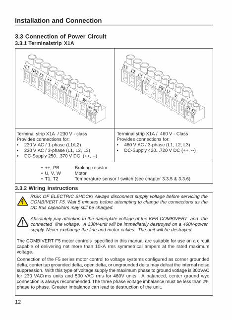
3.3 Connection of Power Circuit3.3.1 Terminalstrip X1A
Terminal strip X1A / 230 V - classProvides connections for:• 230 V AC / 1-phase (L1/L2)• 230 V AC / 3-phase (L1, L2, L3)• DC-Supply 250...370 V DC (++, --)
Terminal strip X1A / 460 V - ClassProvides connections for:• 460 V AC / 3-phase (L1, L2, L3)• DC-Supply 420...720 V DC (++, --)
RISK OF ELECTRIC SHOCK! Always disconnect supply voltage before servicing theCOMBIVERT F5. Wait 5 minutes before attempting to change the connections as theDC Bus capacitors may still be charged.
Absolutely pay attention to the nameplate voltage of the KEB COMBIVERT and theconnected line voltage. A 230V-unit will be immediately destroyed on a 460V-powersupply. Never exchange the line and motor cables. The unit will be destroyed.
The COMBIVERT F5 motor controls specified in this manual are suitable for use on a circuitcapable of delivering not more than 10kA rms symmetrical ampers at the rated maximumvoltage.
Connection of the F5 series motor control to voltage systems configured as corner groundeddelta, center tap grounded delta, open delta, or ungrounded delta may defeat the internal noisesuppression. With this type of voltage supply the maximum phase to ground votlage is 300VACfor 230 VACrms units and 500 VAC rms for 460V units. A balanced, center ground wyeconnection is always recommended. The three phase voltage imbalance must be less than 2%phase to phase. Greater imbalance can lead to destruction of the unit.
• ++, PB Braking resistor• U, V, W Motor• T1, T2 Temperature sensor / switch (see chapter 3.3.5 & 3.3.6)
3.3.2 Wiring instructions
13
UPB
T1T2
N/L2
V
-+ ++
--
L3
W
L1PE
UPB
T1T2
L2
V
-+ ++
--
L3
W
L1PE
Installation and Connection
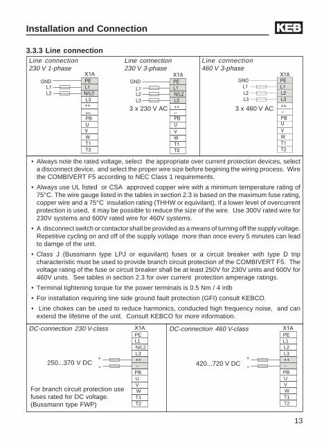
3.3.3 Line connection
• Always note the rated voltage, select the appropriate over current protection devices, selecta disconnect device, and select the proper wire size before begining the wiring process. Wirethe COMBIVERT F5 according to NEC Class 1 requirements.
• Always use UL listed or CSA approved copper wire with a minimum temperature rating of75°C. The wire gauge listed in the tables in section 2.3 is based on the maximum fuse rating,copper wire and a 75°C insulation rating (THHW or equivilant). If a lower level of overcurrentprotection is used, it may be possible to reduce the size of the wire. Use 300V rated wire for230V systems and 600V rated wire for 460V systems.
• A disconnect switch or contactor shall be provided as a means of turning off the supply voltage.Repetitive cycling on and off of the supply votlage more than once every 5 minutes can leadto damge of the unit.
• Class J (Bussmann type LPJ or equivilant) fuses or a circuit breaker with type D tripcharacteristic must be used to provide branch circuit protection of the COMBIVERT F5. Thevoltage rating of the fuse or circuit breaker shall be at least 250V for 230V units and 600V for460V units. See tables in section 2.3 for over current protection amperage ratings.
• Terminal tightening torque for the power terminals is 0.5 Nm / 4 inlb
• For installation requiring line side ground fault protection (GFI) consult KEBCO.
• Line chokes can be used to reduce harmonics, conducted high frequency noise, and canextend the lifetime of the unit. Consult KEBCO for more information.
DC-connection 230 V-class DC-connection 460 V-class
250...370 V DC 420...720 V DC
For branch circuit protection usefuses rated for DC voltage.(Bussmann type FWP)
Line connection230 V 3-phase
Line connection230 V 1-phase
Line connection460 V 3-phase
3 x 230 V AC 3 x 460 V AC
14
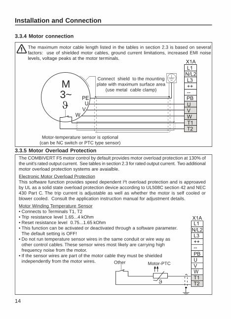
M3~
3.3.5 Motor Overload Protection
The COMBIVERT F5 motor control by default provides motor overload protection at 130% ofthe unit’s rated output current. See tables in section 2.3 for rated output current. Two additionalmotor overload protection systems are avaialble.
Electronic Motor Overload ProtectionThis software function provides speed dependent I2t overload protection and is approavedby UL as a solid state overload protection device according to UL508C section 42 and NEC430 Part C. The trip current is adjustable as well as whether the motor is self cooled orblower cooled. Consult the application instruction manual for adjustment details.
Motor Winding Temperature Sensor• Connects to Terminals T1, T2• Trip resistance level 1.65...4 kOhm• Reset resistance level 0.75...1.65 kOhm• This function can be activated or deactivated through a software parameter.
The default setting is OFF!• Do not run temperature sensor wires in the same conduit or wire way as
other control cables. These sensor wires most likely are carrying highfrequency noise from the motor.
• If the sensor wires are part of the motor cable they must be shieldedindependently from the motor wires. Motor-PTCOther
Installation and Connection
3.3.4 Motor connection
The maximum motor cable length listed in the tables in section 2.3 is based on severalfactors: use of shielded motor cables, ground current limitations, increased EMI noiselevels, voltage peaks at the motor terminals.
Connect shield to the mountingplate with maximum surface area
(use metal cable clamp)
Motor-temperature sensor is optional(can be NC switch or PTC type sensor)
15
Installation and Connection
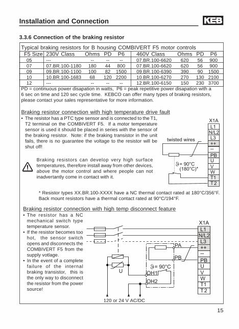
3.3.6 Connection of the braking resistor
Braking resistor connection with high temp disconnect feature• The resistor has a NC
mechanical switch typetemperature sensor.
• If the resistor becomes toohot, the sensor switchopens and disconnects theCOMBIVERT F5 from thesupply votlage.
• In the event of a completefailure of the internalbraking transistor, this isthe only way to disconnectthe resistor from the powersource!
Braking resistors can develop very high surfacetemperatures, therefore install away from other devices,above the motor control and where people can notinadvertantly come in contact with it.
120 or 24 V AC/DC
!"# $"!
Braking resistor connection with high temperature drive fault• The resistor has a PTC type sensor and is connected to the T1,
T2 terminal on the COMBIVERT F5. If a motor temperaturesensor is used it should be placed in series with the sensor ofthe braking resistor. Note: if the braking transistor in the unitfails, there is no guarantee the voltage to the resistor will beshut off!
Typical braking resistors for B housing COMBIVERT F5 motor controls F5 Size 230V Class Ohms PD P6 460V Class Ohms PD P6 05 --- -- -- -- 07.BR.100-6620 620 56 900 07 07.BR.100-1180 180 44 800 07.BR.100-6620 620 56 900 09 09.BR.100-1100 100 82 1500 09.BR.100-6390 390 90 1500 10 10.BR.100-1683 68 120 2200 10.BR.100-6270 270 130 2100 12 --- -- -- -- 12.BR.100-6150 150 230 3700PD = continuous power disapation in watts, P6 = peak repetitive power disapation with a6 sec on time and 120 sec cycle time. KEBCO can offer many types of braking resistors,please contact your sales representative for more information.
* Resistor types XX.BR.100-XXXX have a NC thermal contact rated at 180°C/356°F.Back mount resistors have a thermal contact rated at 90°C/194°F.
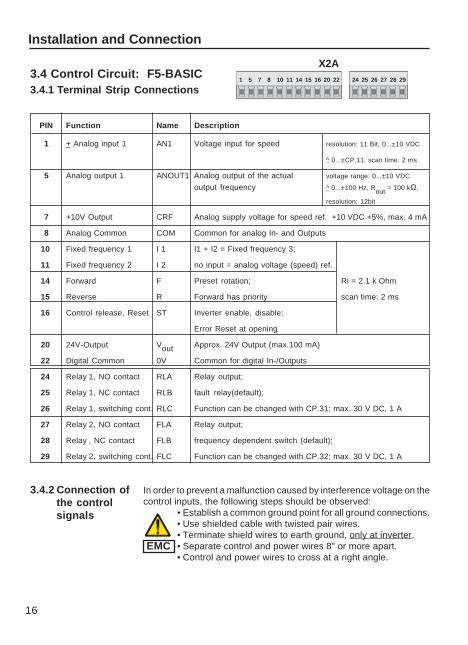
16
In order to prevent a malfunction caused by interference voltage on thecontrol inputs, the following steps should be observed:
• Establish a common ground point for all ground connections.• Use shielded cable with twisted pair wires.• Terminate shield wires to earth ground, only at inverter.• Separate control and power wires 8" or more apart.• Control and power wires to cross at a right angle.
PIN Function Name Description
1 + Analog input 1 AN1 Voltage input for speed resolution: 11 Bit, 0...±10 VDC
^ 0...±CP.11, scan time: 2 ms
5 Analog output 1 ANOUT1 Analog output of the actual voltage range: 0...±10 VDC
output frequency ^ 0...±100 Hz, Rout = 100 kΩ,
resolution: 12bit
7 +10V Output CRF Analog supply voltage for speed ref. +10 VDC +5%, max. 4 mA
8 Analog Common COM Common for analog In- and Outputs
10 Fixed frequency 1 I 1 I1 + I2 = Fixed frequency 3;
11 Fixed frequency 2 I 2 no input = analog voltage (speed) ref.
14 Forward F Preset rotation; Ri = 2.1 k Ohm
15 Reverse R Forward has priority scan time: 2 ms
16 Control release, Reset ST Inverter enable, disable;
Error Reset at opening
20 24V-Output Vout Approx. 24V Output (max.100 mA)
22 Digital Common 0V Common for digital In-/Outputs
24 Relay 1, NO contact RLA Relay output;
25 Relay 1, NC contact RLB fault relay(default);
26 Relay 1, switching cont. RLC Function can be changed with CP.31; max. 30 V DC, 1 A
27 Relay 2, NO contact FLA Relay output;
28 Relay , NC contact FLB frequency dependent switch (default);
29 Relay 2, switching cont. FLC Function can be changed with CP.32; max. 30 V DC, 1 A
Installation and Connection
3.4.2 Connection ofthe controlsignals
1 5 7 8 10 11 14 15 16 20 22 24 25 26 27 28 29
X2A
3.4.1 Terminal Strip Connections3.4 Control Circuit: F5-BASIC
EMC
17
Installation and Connection
Internal analogspeed ref. setting
External analogspeed ref. setting
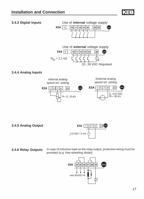
3.4.5 Analog Output
3.4.4 Analog Inputs
3.4.3 Digital Inputs
In case of inductive load on the relay output, protective wiring must beprovided (e.g. free-wheeling diode)!
3.4.6 Relay Outputs
Rin = 2.1 kΩ
Use of external voltage supply
Use of internal voltage supply
20...30 VDC Regulated
18
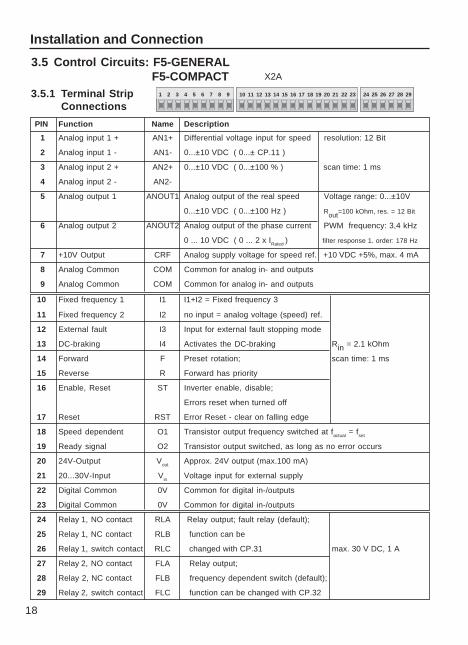
3.5.1 Terminal StripConnections
3.5 Control Circuits: F5-GENERAL F5-COMPACT
1 2 3 4 5 6 7 8 9 10 11 12 13 14 15 16 17 18 19 20 21 22 23 24 25 26 27 28 29
X2A
PIN Function Name Description
1 Analog input 1 + AN1+ Differential voltage input for speed resolution: 12 Bit
2 Analog input 1 - AN1- 0...±10 VDC ( 0...± CP.11 )
3 Analog input 2 + AN2+ 0...±10 VDC ( 0...±100 % ) scan time: 1 ms
4 Analog input 2 - AN2-
5 Analog output 1 ANOUT1 Analog output of the real speed Voltage range: 0...±10V
0...±10 VDC ( 0...±100 Hz ) Rout=100 kOhm, res. = 12 Bit
6 Analog output 2 ANOUT2 Analog output of the phase current PWM frequency: 3,4 kHz
0 ... 10 VDC ( 0 ... 2 x IRated ) filter response 1. order: 178 Hz
7 +10V Output CRF Analog supply voltage for speed ref. +10 VDC +5%, max. 4 mA
8 Analog Common COM Common for analog in- and outputs
9 Analog Common COM Common for analog in- and outputs
10 Fixed frequency 1 I1 I1+I2 = Fixed frequency 3
11 Fixed frequency 2 I2 no input = analog voltage (speed) ref.
12 External fault I3 Input for external fault stopping mode
13 DC-braking I4 Activates the DC-braking Rin = 2.1 kOhm
14 Forward F Preset rotation; scan time: 1 ms
15 Reverse R Forward has priority
16 Enable, Reset ST Inverter enable, disable;
Errors reset when turned off
17 Reset RST Error Reset - clear on falling edge
18 Speed dependent O1 Transistor output frequency switched at factual = fset
19 Ready signal O2 Transistor output switched, as long as no error occurs
20 24V-Output Vout Approx. 24V output (max.100 mA)
21 20...30V-Input Vin Voltage input for external supply
22 Digital Common 0V Common for digital in-/outputs
23 Digital Common 0V Common for digital in-/outputs
24 Relay 1, NO contact RLA Relay output; fault relay (default);
25 Relay 1, NC contact RLB function can be
26 Relay 1, switch contact RLC changed with CP.31 max. 30 V DC, 1 A
27 Relay 2, NO contact FLA Relay output;
28 Relay 2, NC contact FLB frequency dependent switch (default);
29 Relay 2, switch contact FLC function can be changed with CP.32
Installation and Connection
19
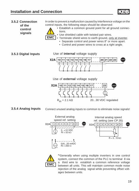
3.5.2 Connectionof thecontrolsignals
In order to prevent a malfunction caused by interference voltage on thecontrol inputs, the following steps should be observed:
• Establish a common ground point for all ground connec-tions.
• Use shielded cable with twisted pair wires.• Terminate shield wires to earth ground, only at inverter.
• Separate control and power wires 8" or more apart.• Control and power wires to cross at a right angle.
3.5.4 Analog Inputs
3.5.3 Digital Inputs
Use of external voltage supply
Use of internal voltage supply
Connect unused analog inputs to common to eliminate noise signals!
External analogspeed ref. setting
Internal analog speedref. setting (see CP.35)
Rin = 2.1 kΩ
*)Generally when using multiple inverters in one controlsystem, connect the common of the PLC to terminal 8 viaa third wire to establish a common reference voltagebetween all units. This will maintain common mode noiserejection of the analog signal while preventing offset volt-ages between units.
*
*
20...30 VDC regulated
Installation and Connection
EMC
EMC
20
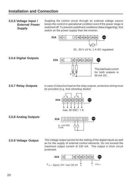
3.5.7 Relay Outputs
3.5.8 Analog Outputs
3.5.6 Digital Outputs
The total load currentfor both outputs is50 mA DC .
3.5.9 Voltage Output
3.5.5 Voltage Input /External PowerSupply
Installation and Connection
In case of inductive load on the relay outputs, protective wiring mustbe provided (e.g. free-wheeling diode)!
The voltage output serves for the setting of the digital inputs as wellas for the supply of external control elements. Do not exceed themaximum output current of 100 mA. This output is short circuitprotected.
Suppling the control circuit through an external voltage sourcekeeps the control in operational condition even if the power stage isswitched off. To prevent undefined conditions (false triggering), firstswitch on the power supply than the inverter.
20...30 V ±0 %, 1 A DC regulated
!!"#$$%!
21
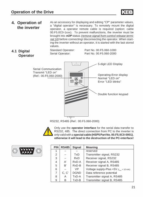
As an accessory for displaying and editing "CP" parameter values,a "digital operator" is necessary. To remotely mount the digitaloperator, a operator remote cable is required (option: cable00.F5.0C0-1xxx). To prevent malfunctions, the inverter must bebrought into nOP status (remove signal from control release termi-nal 16) before connecting/ disconnecting the operator. When start-ing the inverter without an operator, it is started with the last storedvalues.
4. Operation ofthe inverter
Operation of the Drive
4.1 DigitalOperator
Only use the operator interface for the serial data transfer toRS232, 485. The direct connection from PC to the inverter isonly valid with a special cable (HSP5 Part No. 00.F5.0C0-0001),otherwise it will lead to the destruction of the PC-interface!
Standard Operator: Part No. 00.F5.060-1000Serial Operator: Part No. 00.F5.060-2000
5 4 3 2 1
9 8 7 6
ANTRIEBSTECHNIK
START
STOP
FUNC.
SPEED
ENTER
F/R
Double function keypad
Operating-Error displayNormal "LED on"Error "LED blinks"
5-digit LED Display
Serial CommunicationTransmit "LED on"(Ref.: 00.F5.060-2000)
RS232, RS485 (Ref.: 00.F5.060-2000)
PIN RS485 Signal Meaning 1 – – reserved 2 – TxD Transmitter signal, RS232 3 – RxD Receiver signal, RS232 4 A' RxD-A Receiver signal A, RS485 5 B' RxD-B Receiver signal B, RS485 6 – VP Voltage supply-Plus +5V (Imax = 10 mA)
7 C, C' DGND Data reference potential 8 A TxD-A Transmitter signal A, RS485 9 B TxD-B Transmitter signal B, RS485
22
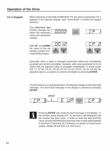
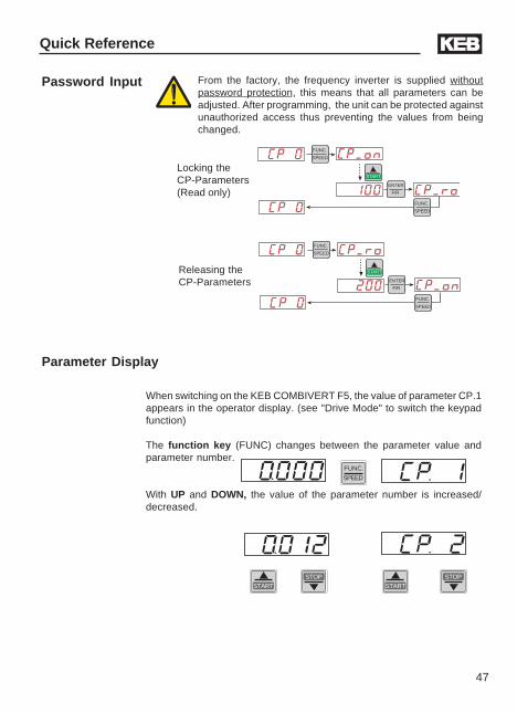
When switching on the KEB COMBIVERT F5, the value of parameter CP.1appears in the operator display. (see "Drive Mode" to switch the keypadfunction)
The function key(FUNC) changes be-tween the parametervalue and parameternumber.
With UP and DOWN,the value of the pa-rameter number is in-creased/decreased.
Generally; when a value is changed, parameter values are immediatelyaccepted and stored nonvolatile. However, with some parameters it is notuseful that the adjusted value is accepted immediately. In these cases(CP.17, CP.18, CP.22, CP.26, CP.29, CP.31, CP.32, CP.34, CP.35) theadjusted value is accepted an stored nonvolatile by pressing ENTER.
If a drive fault occurs during operation, the display changes to the drive faultmessage. The drive fault message in the display is cleared by pressingENTER.
Operation of the Drive
4.1.1 Keypad
Pressing ENTER only clears the fault message in the display. Inthe Inverter status display (CP. 3), the fault is still displayed untilthe inverter has been reset. In order to reset the fault itself thecause must be identified and removed, than a reset signal appliedto terminal 17 terminal 16, F5-Basic or a power-on reset (cyclesupply voltage off and then on) must occur.
FUNC.
SPEED
START
STOP
START
STOP
ENTER
F/R
error
23
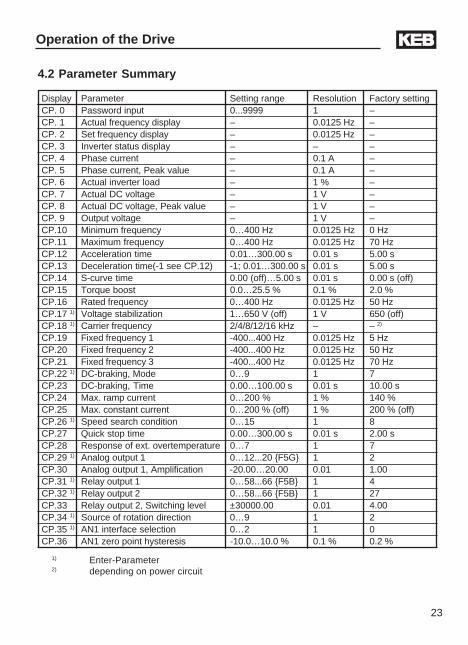
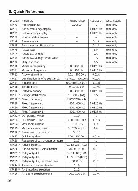
Display Parameter Setting range Resolution Factory settingCP. 0 Password input 0...9999 1 –CP. 1 Actual frequency display – 0.0125 Hz –CP. 2 Set frequency display – 0.0125 Hz –CP. 3 Inverter status display – – –CP. 4 Phase current – 0.1 A –CP. 5 Phase current, Peak value – 0.1 A –CP. 6 Actual inverter load – 1 % –CP. 7 Actual DC voltage – 1 V –CP. 8 Actual DC voltage, Peak value – 1 V –CP. 9 Output voltage – 1 V –CP.10 Minimum frequency 0…400 Hz 0.0125 Hz 0 HzCP.11 Maximum frequency 0…400 Hz 0.0125 Hz 70 HzCP.12 Acceleration time 0.01…300.00 s 0.01 s 5.00 sCP.13 Deceleration time(-1 see CP.12) -1; 0.01…300.00 s 0.01 s 5.00 sCP.14 S-curve time 0.00 (off)…5.00 s 0.01 s 0.00 s (off)CP.15 Torque boost 0.0…25.5 % 0.1 % 2.0 %CP.16 Rated frequency 0…400 Hz 0.0125 Hz 50 HzCP.17 1) Voltage stabilization 1…650 V (off) 1 V 650 (off)CP.18 1) Carrier frequency 2/4/8/12/16 kHz – – 2)
CP.19 Fixed frequency 1 -400...400 Hz 0.0125 Hz 5 HzCP.20 Fixed frequency 2 -400...400 Hz 0.0125 Hz 50 HzCP.21 Fixed frequency 3 -400...400 Hz 0.0125 Hz 70 HzCP.22 1) DC-braking, Mode 0…9 1 7CP.23 DC-braking, Time 0.00…100.00 s 0.01 s 10.00 sCP.24 Max. ramp current 0…200 % 1 % 140 %CP.25 Max. constant current 0…200 % (off) 1 % 200 % (off)CP.26 1) Speed search condition 0…15 1 8CP.27 Quick stop time 0.00…300.00 s 0.01 s 2.00 sCP.28 Response of ext. overtemperature 0…7 1 7CP.29 1) Analog output 1 0…12...20 F5G 1 2CP.30 Analog output 1, Amplification -20.00…20.00 0.01 1.00CP.31 1) Relay output 1 0…58...66 F5B 1 4CP.32 1) Relay output 2 0…58...66 F5B 1 27CP.33 Relay output 2, Switching level ±30000.00 0.01 4.00CP.34 1) Source of rotation direction 0…9 1 2CP.35 1) AN1 interface selection 0…2 1 0CP.36 AN1 zero point hysteresis -10.0…10.0 % 0.1 % 0.2 %
Operation of the Drive
4.2 Parameter Summary
1) Enter-Parameter2) depending on power circuit
24
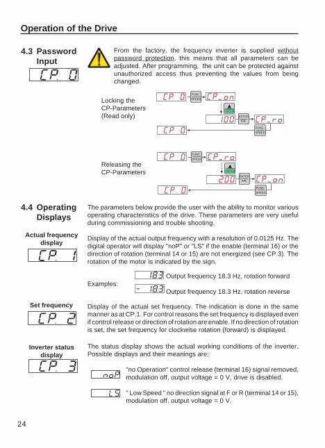
The parameters below provide the user with the ability to monitor variousoperating characteristics of the drive. These parameters are very usefulduring commissioning and trouble shooting.
Display of the actual output frequency with a resolution of 0.0125 Hz. Thedigital operator will display "noP" or "LS" if the enable (terminal 16) or thedirection of rotation (terminal 14 or 15) are not energized (see CP.3). Therotation of the motor is indicated by the sign.
Output frequency 18.3 Hz, rotation forwardExamples:
Output frequency 18.3 Hz, rotation reverse
4.4 OperatingDisplays
Actual frequencydisplay
Inverter statusdisplay
The status display shows the actual working conditions of the inverter.Possible displays and their meanings are:
"no Operation" control release (terminal 16) signal removed,modulation off, output voltage = 0 V, drive is disabled.
" Low Speed " no direction signal at F or R (terminal 14 or 15),modulation off, output voltage = 0 V.
Display of the actual set frequency. The indication is done in the samemanner as at CP.1. For control reasons the set frequency is displayed evenif control release or direction of rotation are enable. If no direction of rotationis set, the set frequency for clockwise rotation (forward) is displayed.
Set frequency
Operation of the Drive
4.3 PasswordInput
FUNC.
SPEED
START
FUNC.
SPEED
ENTER
F/R
FUNC.
SPEED
START
FUNC.
SPEED
ENTER
F/R
Releasing theCP-Parameters
Locking theCP-Parameters(Read only)
From the factory, the frequency inverter is supplied withoutpassword protection, this means that all parameters can beadjusted. After programming, the unit can be protected againstunauthorized access thus preventing the values from beingchanged.
25
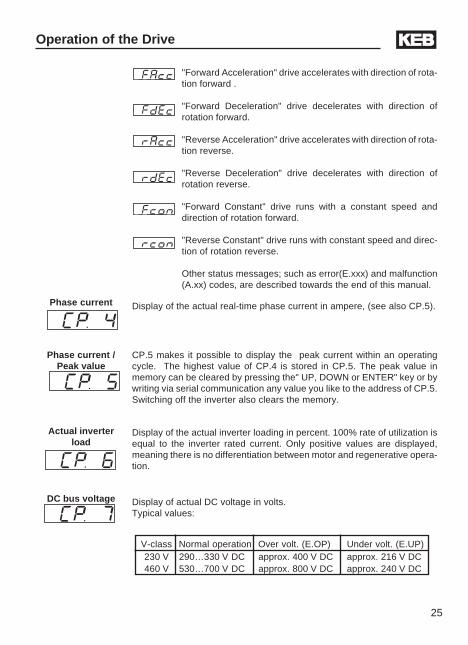
V-class Normal operation Over volt. (E.OP) Under volt. (E.UP)230 V 290…330 V DC approx. 400 V DC approx. 216 V DC460 V 530…700 V DC approx. 800 V DC approx. 240 V DC
"Forward Acceleration" drive accelerates with direction of rota-tion forward .
"Forward Deceleration" drive decelerates with direction ofrotation forward.
"Reverse Acceleration" drive accelerates with direction of rota-tion reverse.
"Reverse Deceleration" drive decelerates with direction ofrotation reverse.
"Forward Constant" drive runs with a constant speed anddirection of rotation forward.
"Reverse Constant" drive runs with constant speed and direc-tion of rotation reverse.
Other status messages; such as error(E.xxx) and malfunction(A.xx) codes, are described towards the end of this manual.
Operation of the Drive
Phase current Display of the actual real-time phase current in ampere, (see also CP.5).
DC bus voltage Display of actual DC voltage in volts.Typical values:
CP.5 makes it possible to display the peak current within an operatingcycle. The highest value of CP.4 is stored in CP.5. The peak value inmemory can be cleared by pressing the" UP, DOWN or ENTER" key or bywriting via serial communication any value you like to the address of CP.5.Switching off the inverter also clears the memory.
Phase current /Peak value
Actual inverterload
Display of the actual inverter loading in percent. 100% rate of utilization isequal to the inverter rated current. Only positive values are displayed,meaning there is no differentiation between motor and regenerative opera-tion.
26
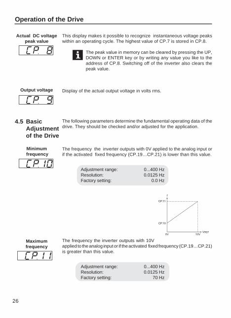
This display makes it possible to recognize instantaneous voltage peakswithin an operating cycle. The highest value of CP.7 is stored in CP.8.
The peak value in memory can be cleared by pressing the UP,DOWN or ENTER key or by writing any value you like to theaddress of CP.8. Switching off of the inverter also clears thepeak value.
Display of the actual output voltage in volts rms.
4.5 BasicAdjustmentof the Drive
Actual DC voltagepeak value
Output voltage
Minimum frequency
Maximumfrequency
Operation of the Drive
The following parameters determine the fundamental operating data of thedrive. They should be checked and/or adjusted for the application.
The frequency the inverter outputs with 0V applied to the analog input orif the activated fixed frequency (CP.19…CP.21) is lower than this value.
Adjustment range: 0...400 HzResolution: 0.0125 HzFactory setting: 0.0 Hz
The frequency the inverter outputs with 10Vapplied to the analog input or if the activated fixed frequency (CP.19…CP.21)is greater than this value.
Adjustment range: 0...400 HzResolution: 0.0125 HzFactory setting: 70 Hz
27
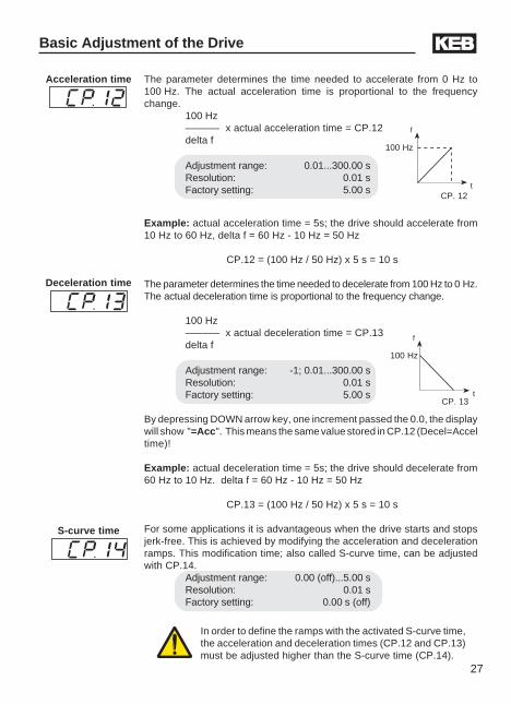
The parameter determines the time needed to accelerate from 0 Hz to100 Hz. The actual acceleration time is proportional to the frequencychange.
100 Hz–––––– x actual acceleration time = CP.12delta f
Adjustment range: 0.01...300.00 sResolution: 0.01 sFactory setting: 5.00 s
Example: actual acceleration time = 5s; the drive should accelerate from10 Hz to 60 Hz, delta f = 60 Hz - 10 Hz = 50 Hz
CP.12 = (100 Hz / 50 Hz) x 5 s = 10 s
The parameter determines the time needed to decelerate from 100 Hz to 0 Hz.The actual deceleration time is proportional to the frequency change.
100 Hz–––––– x actual deceleration time = CP.13delta f
Adjustment range: -1; 0.01...300.00 sResolution: 0.01 sFactory setting: 5.00 s
By depressing DOWN arrow key, one increment passed the 0.0, the displaywill show "=Acc". This means the same value stored in CP.12 (Decel=Acceltime)!
Example: actual deceleration time = 5s; the drive should decelerate from60 Hz to 10 Hz. delta f = 60 Hz - 10 Hz = 50 Hz
CP.13 = (100 Hz / 50 Hz) x 5 s = 10 s
For some applications it is advantageous when the drive starts and stopsjerk-free. This is achieved by modifying the acceleration and decelerationramps. This modification time; also called S-curve time, can be adjustedwith CP.14.
Adjustment range: 0.00 (off)...5.00 sResolution: 0.01 sFactory setting: 0.00 s (off)
Basic Adjustment of the Drive
Acceleration time
Deceleration time
S-curve time
In order to define the ramps with the activated S-curve time,the acceleration and deceleration times (CP.12 and CP.13)must be adjusted higher than the S-curve time (CP.14).
100 Hz
CP. 12
f
t
100 Hz
CP. 13
f
t
28
Basic Adjustment of the Drive
Boost
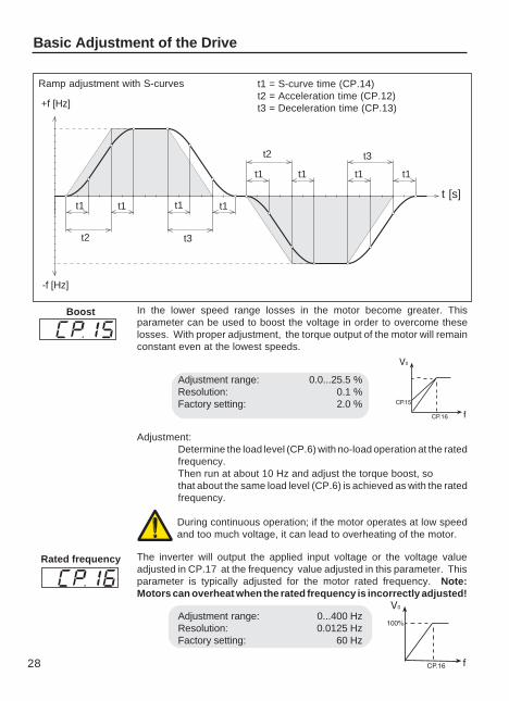
t1 t1 t1 t1
t2 t3
+f [Hz]
-f [Hz]
t [s]
t1 = S-curve time (CP.14)t2 = Acceleration time (CP.12)t3 = Deceleration time (CP.13)
t1t1
t2 t3
Ramp adjustment with S-curves
The inverter will output the applied input voltage or the voltage valueadjusted in CP.17 at the frequency value adjusted in this parameter. Thisparameter is typically adjusted for the motor rated frequency. Note:Motors can overheat when the rated frequency is incorrectly adjusted!
Adjustment range: 0...400 HzResolution: 0.0125 HzFactory setting: 60 Hz
Rated frequency
t1t1
In the lower speed range losses in the motor become greater. Thisparameter can be used to boost the voltage in order to overcome theselosses. With proper adjustment, the torque output of the motor will remainconstant even at the lowest speeds.
Adjustment range: 0.0...25.5 %Resolution: 0.1 %Factory setting: 2.0 %
Adjustment:Determine the load level (CP.6) with no-load operation at the ratedfrequency.Then run at about 10 Hz and adjust the torque boost, sothat about the same load level (CP.6) is achieved as with the ratedfrequency.
During continuous operation; if the motor operates at low speedand too much voltage, it can lead to overheating of the motor.
29
Basic Adjustment of the Drive
4.6 Special AdjustmentsThe following parameters serve for the optimization of the drive and theadaptation to certain applications. These adjustments can be ignored atinitial start-up.
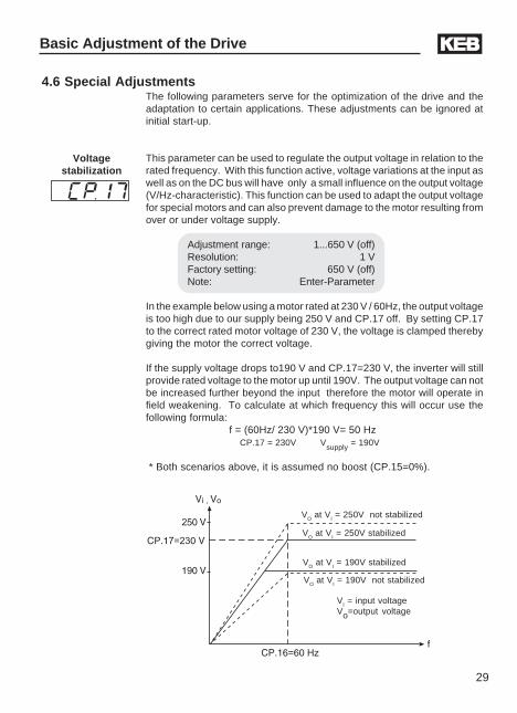
This parameter can be used to regulate the output voltage in relation to therated frequency. With this function active, voltage variations at the input aswell as on the DC bus will have only a small influence on the output voltage(V/Hz-characteristic). This function can be used to adapt the output voltagefor special motors and can also prevent damage to the motor resulting fromover or under voltage supply.
Adjustment range: 1...650 V (off)Resolution: 1 VFactory setting: 650 V (off)Note: Enter-Parameter
In the example below using a motor rated at 230 V / 60Hz, the output voltageis too high due to our supply being 250 V and CP.17 off. By setting CP.17to the correct rated motor voltage of 230 V, the voltage is clamped therebygiving the motor the correct voltage.
If the supply voltage drops to190 V and CP.17=230 V, the inverter will stillprovide rated voltage to the motor up until 190V. The output voltage can notbe increased further beyond the input therefore the motor will operate infield weakening. To calculate at which frequency this will occur use thefollowing formula:
f = (60Hz/ 230 V)*190 V= 50 Hz CP.17 = 230V Vsupply = 190V
* Both scenarios above, it is assumed no boost (CP.15=0%).
Voltagestabilization
VO at VI = 250V stabilized
VO at VI = 250V not stabilized
VO at VI = 190V stabilized
VO at VI = 190V not stabilized
VI = input voltageVo=output voltage
30
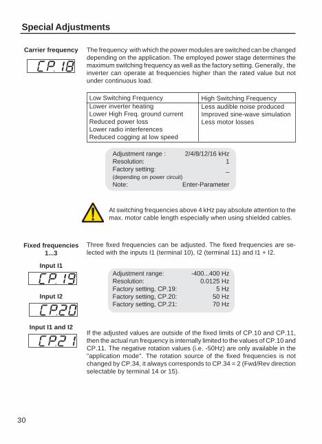
Fixed frequencies1...3
Input I1
Input I2
Input I1 and I2
Three fixed frequencies can be adjusted. The fixed frequencies are se-lected with the inputs I1 (terminal 10), I2 (terminal 11) and I1 + I2.
Adjustment range: -400...400 HzResolution: 0.0125 HzFactory setting, CP.19: 5 HzFactory setting, CP.20: 50 HzFactory setting, CP.21: 70 Hz
If the adjusted values are outside of the fixed limits of CP.10 and CP.11,then the actual run frequency is internally limited to the values of CP.10 andCP.11. The negative rotation values (i.e. -50Hz) are only available in the"application mode". The rotation source of the fixed frequencies is notchanged by CP.34, it always corresponds to CP.34 = 2 (Fwd/Rev directionselectable by terminal 14 or 15).
Adjustment range : 2/4/8/12/16 kHzResolution: 1Factory setting: _(depending on power circuit)Note: Enter-Parameter
Low Switching FrequencyLower inverter heatingLower High Freq. ground currentReduced power lossLower radio interferencesReduced cogging at low speed
High Switching FrequencyLess audible noise producedImproved sine-wave simulationLess motor losses
Carrier frequency The frequency with which the power modules are switched can be changeddepending on the application. The employed power stage determines themaximum switching frequency as well as the factory setting. Generally, theinverter can operate at frequencies higher than the rated value but notunder continuous load.
Special Adjustments
At switching frequencies above 4 kHz pay absolute attention to themax. motor cable length especially when using shielded cables.
31
DC-braking Mode
Special Adjustments
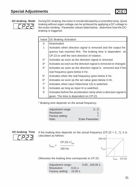
If the braking time depends on the actual frequency (CP.22 = 2...7), it iscalculated as follows:
CP.23 x freal
tBrake = –––––––––100 Hz
Otherwise the braking time corresponds to CP.23.
Adjustment range: 0.00...100.00 sResolution: 0.01 sFactory setting: 10.00 s
DC-braking Timef
t
100 Hz
factual
tBrake CP.23
During DC-braking, the motor is not decelerated by a controlled ramp. Quickbraking without regen voltage can be achieved by applying a DC voltage tothe motor winding. Parameter values listed below, determine how the DC-braking is triggered.
Value DC-Braking Activation
0 Deactivated
1 Activates when direction signal is removed and the output fre-
quency has reached 0Hz. The braking time is dependent on
CP.23 or until the next direction of rotation.
2* Activates as soon as the direction signal is removed.
3* Activates as soon as the direction signal is removed or changed.
4* Activates as soon as the direction signal is removed and if the
real frequency goes below 4 Hz.
5* Activates when the real frequency goes below 4 Hz.
6* Activates as soon as the set value goes below 4 Hz.
7* Activates when input I4(terminal 13) is switched.
8 Activates as long as input I4 is switched.
9 Activates before the acceleration ramp when a direction signal is
given. The time is dependent on CP.23.
* Braking time depends on the actual frequency.
Adjustment range: 0...9Resolution: 1Factory setting: 7Note: Enter-Parameter
32
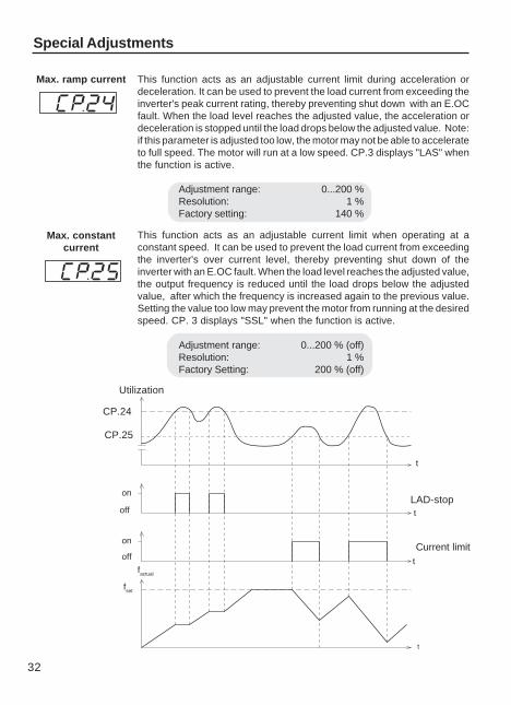
This function acts as an adjustable current limit when operating at aconstant speed. It can be used to prevent the load current from exceedingthe inverter's over current level, thereby preventing shut down of theinverter with an E.OC fault. When the load level reaches the adjusted value,the output frequency is reduced until the load drops below the adjustedvalue, after which the frequency is increased again to the previous value.Setting the value too low may prevent the motor from running at the desiredspeed. CP. 3 displays "SSL" when the function is active.
Adjustment range: 0...200 % (off)Resolution: 1 %Factory Setting: 200 % (off)
t
fset
factual
on
off
on
off
CP.25
CP.24
LAD-stop
Current limit
t
t
t
Max. constantcurrent
Utilization
This function acts as an adjustable current limit during acceleration ordeceleration. It can be used to prevent the load current from exceeding theinverter's peak current rating, thereby preventing shut down with an E.OCfault. When the load level reaches the adjusted value, the acceleration ordeceleration is stopped until the load drops below the adjusted value. Note:if this parameter is adjusted too low, the motor may not be able to accelerateto full speed. The motor will run at a low speed. CP.3 displays "LAS" whenthe function is active.
Adjustment range: 0...200 %Resolution: 1 %Factory setting: 140 %
Max. ramp current
Special Adjustments
33
Special Adjustments
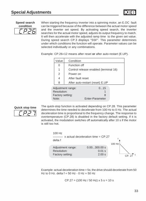
When starting the frequency inverter into a spinning motor, an E.OC faultcan be triggered because of the difference between the actual motor speedand the inverter set speed. By activating speed search, the invertersearches for the actual motor speed, adjusts its output frequency to match.It will then accelerate with the adjusted ramp time to the given set value.During speed search CP.3 displays "SSF". This parameter determinesunder which conditions the function will operate. Parameter values can beselected individually or any combinations.
Example: CP.26=12 means after reset or after auto-restart (E.UP).
Speed searchcondition
Adjustment range: 0...15Resolution: 1Factory setting: 8Note: Enter-Parameter
Value Condition
0 Function off
1 Control release enabled (terminal 16)
2 Power on
4 After fault reset
8 After auto-restart (reset) E.UP
100 Hz
f
t
Quick stop time
CP. 27
The quick-stop function is activated depending on CP.28. This parameterdetermines the time needed to decelerate from 100 Hz to 0 Hz. The actualdeceleration time is proportional to the frequency change. The response toovertemperature (CP.28) is disabled in the factory default setting. If it isactivated, the modulation switches off automatically after 10 s if the motoris still too hot.
100 Hz–––––– x actual deceleration time = CP.27delta f
Adjustment range: 0.00...300.00 sResolution: 0.01 sFactory setting: 2.00 s
Example: actual deceleration time = 5s; the drive should decelerate from 50Hz to 0 Hz. delta f = 50 Hz - 0 Hz = 50 Hz
CP.27 = (100 Hz / 50 Hz) x 5 s = 10 s
34
Response toexternal
overtemperature
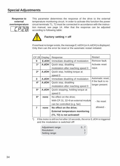
Adjustment range: 0...7Resolution: 1Setting range: 7
This parameter determines the response of the drive to the externaltemperature monitoring circuit. In order to activate this function the powercircuit terminals T1, T2 must be connected in accordance with the instruc-tion manual, see page 14. After that the response can be adjustedaccording to following table:
CP.28 Display Response
0 E.dOH Immediate disabling of modulation
1* A.dOH Quick stop, disabling
modulation after reaching speed 0
2* A.dOH Quick stop, holding torque at
speed 0
3 A.dOH Immediate disabling of modulation
4* A.dOH Quick stop, disabling
modulation after reaching speed 0
5* A.dOH Quick stopping, holding torque at
speed 0
6* none No effect on the drive;
With CP.31, 32=9 an external module
can be controlled (e.g. fan)
7 none No effect on the drive;
External temperature monitoring
(T1, T2) is not activated!
Restart
Remove fault;
Activate reset
input.
Automatic reset,if the fault is nolonger present
- No reset
allowed -
*) If the motor is still too hot after 10 seconds, the error E.dOH is triggeredand the modulation is switched off!
Special Adjustments
If overheat no longer exists, the message E.ndOH (or A.ndOH) is displayed.Only then can the error be reset or the automatic restart initiated.
Factory setting = off
35
Special Adjustments
Analog output 1
Analog output 1Amplification
10V
CP.30
100%
-100% 100%
-100%
in
out
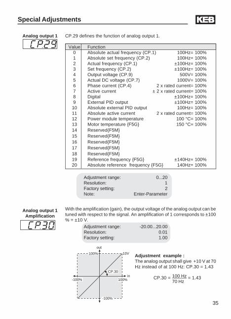
Adjustment example :The analog output shall give +10 V at 70Hz instead of at 100 Hz: CP.30 = 1.43
100 HzCP.30 = -––––– = 1.4370 Hz
With the amplification (gain), the output voltage of the analog output can betuned with respect to the signal. An amplification of 1 corresponds to ±100% = ±10 V.
Adjustment range: 0...20Resolution: 1Factory setting: 2Note: Enter-Parameter
Adjustment range: -20.00...20.00Resolution: 0.01Factory setting: 1.00
CP.29 defines the function of analog output 1.
Value Function0 Absolute actual frequency (CP.1) 100Hz= 100%1 Absolute set frequency (CP.2) 100Hz= 100%2 Actual frequency (CP.1) ±100Hz= 100%3 Set frequency (CP.2) ±100Hz= 100%4 Output voltage (CP.9) 500V= 100%5 Actual DC voltage (CP.7) 1000V= 100%6 Phase current (CP.4) 2 x rated current= 100%7 Active current ± 2 x rated current= 100%8 Digital ±100Hz= 100%9 External PID output ±100Hz= 100%
10 Absolute external PID output 100Hz= 100%11 Absolute active current 2 x rated current= 100%12 Power module temperature 100 °C= 100%13 Motor temperature F5G 150 °C= 100%14 ReservedF5M15 ReservedF5M16 ReservedF5M17 ReservedF5M18 ReservedF5M19 Reference frequency F5G ±140Hz= 100%20 Absolute reference frequency F5G 140Hz= 100%
36
Relay output 1
Relay output 2
Special Adjustments
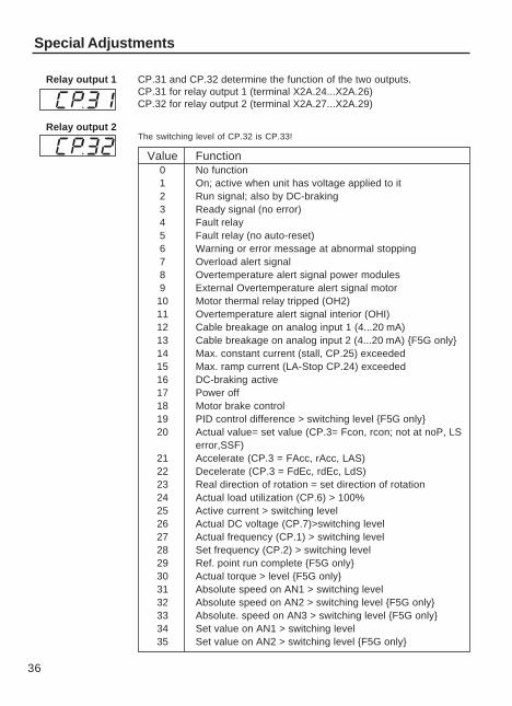
CP.31 and CP.32 determine the function of the two outputs.CP.31 for relay output 1 (terminal X2A.24...X2A.26)CP.32 for relay output 2 (terminal X2A.27...X2A.29)
The switching level of CP.32 is CP.33!
Value Function0 No function1 On; active when unit has voltage applied to it2 Run signal; also by DC-braking3 Ready signal (no error)4 Fault relay5 Fault relay (no auto-reset)6 Warning or error message at abnormal stopping7 Overload alert signal8 Overtemperature alert signal power modules9 External Overtemperature alert signal motor
10 Motor thermal relay tripped (OH2)11 Overtemperature alert signal interior (OHI)12 Cable breakage on analog input 1 (4...20 mA)13 Cable breakage on analog input 2 (4...20 mA) F5G only14 Max. constant current (stall, CP.25) exceeded15 Max. ramp current (LA-Stop CP.24) exceeded16 DC-braking active17 Power off18 Motor brake control19 PID control difference > switching level F5G only20 Actual value= set value (CP.3= Fcon, rcon; not at noP, LS
error,SSF)21 Accelerate (CP.3 = FAcc, rAcc, LAS)22 Decelerate (CP.3 = FdEc, rdEc, LdS)23 Real direction of rotation = set direction of rotation24 Actual load utilization (CP.6) > 100%25 Active current > switching level26 Actual DC voltage (CP.7)>switching level27 Actual frequency (CP.1) > switching level28 Set frequency (CP.2) > switching level29 Ref. point run complete F5G only30 Actual torque > level F5G only31 Absolute speed on AN1 > switching level32 Absolute speed on AN2 > switching level F5G only33 Absolute. speed on AN3 > switching level F5G only34 Set value on AN1 > switching level35 Set value on AN2 > switching level F5G only
37
Value Function
Factory setting CP.31: 4Factory setting CP.32: 27Note: Enter-Parameter
*these functions are currently not supported by the F5G in the B housing.
Special Adjustments
36 Set value on AN3 > switching level F5G only37 Timer 1 > switching level38 Timer 2 > switching level39 Reserved F5M40 Hardware current limit active41 Modulation on-signal42 ANOUT3 PWM43 ANOUT4 PWM F5G only44 Inverter status (ru.0) = switching level45 Power transistor temperature > switching level46 Motor temperature > switching level47 Ramp output > switching level48 Phase current > switching level49 Rotation forward50 Rotation reverse51 OL2 warning F5G only52 Reserved F5M53 Reserved F5M54 Reserved F5M55 Reserved F5M56 Reserved F5M57 Reserved F5M58 Reserved F5M59 Digital input (ru.22 "AND" > switching level F5B only*60 Digital input (ru.22 "OR" > switching level F5B only*61 Digital input (ru.22 "NAND" > switching level F5B only*62 Digital input (ru.22 "NOR" > switching level F5B only*63 Absolute value ANOUT1 > switching level F5B only*64 Reserved F5B only*65 Absolute speed on ANOUT1 > switching level F5B only*66 Reserved F5B only*
67...69 Reserved F5M70 Driver voltage aktiv ( safety relais)
71...72 Reserved F5M73 Absolute value active power > switching level74 active power > switching level75 Reserved F5M
38
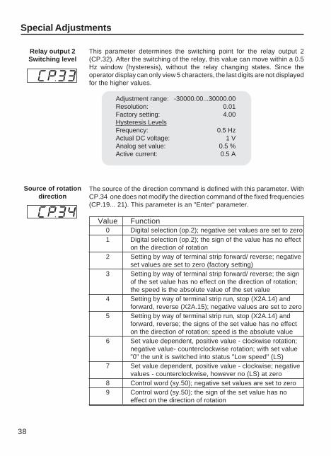
The source of the direction command is defined with this parameter. WithCP.34 one does not modify the direction command of the fixed frequencies(CP.19... 21). This parameter is an "Enter" parameter.
Value Function0 Digital selection (op.2); negative set values are set to zero1 Digital selection (op.2); the sign of the value has no effect
on the direction of rotation2 Setting by way of terminal strip forward/ reverse; negative
set values are set to zero (factory setting)3 Setting by way of terminal strip forward/ reverse; the sign
of the set value has no effect on the direction of rotation;the speed is the absolute value of the set value
4 Setting by way of terminal strip run, stop (X2A.14) andforward, reverse (X2A.15); negative values are set to zero
5 Setting by way of terminal strip run, stop (X2A.14) andforward, reverse; the signs of the set value has no effecton the direction of rotation; speed is the absolute value
6 Set value dependent, positive value - clockwise rotation;negative value- counterclockwise rotation; with set value"0" the unit is switched into status "Low speed" (LS)
7 Set value dependent, positive value - clockwise; negativevalues - counterclockwise, however no (LS) at zero
8 Control word (sy.50); negative set values are set to zero9 Control word (sy.50); the sign of the set value has no
effect on the direction of rotation
Special Adjustments
Relay output 2Switching level
This parameter determines the switching point for the relay output 2(CP.32). After the switching of the relay, this value can move within a 0.5Hz window (hysteresis), without the relay changing states. Since theoperator display can only view 5 characters, the last digits are not displayedfor the higher values.
Adjustment range: -30000.00...30000.00Resolution: 0.01Factory setting: 4.00Hysteresis LevelsFrequency: 0.5 HzActual DC voltage: 1 VAnalog set value: 0.5 %Active current: 0.5 A
Source of rotationdirection
39
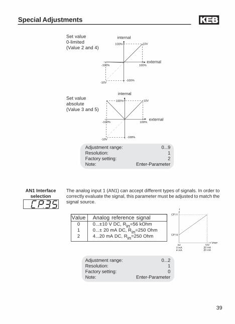
Set value0-limited(Value 2 and 4)
Set valueabsolute(Value 3 and 5)
Adjustment range: 0...9Resolution: 1Factory setting: 2Note: Enter-Parameter
10V100%
-100% 100%
-100%
extern
-10V
interninternal
external
10V100%
-100% 100%
-100%
extern
-10V
interninternal
external
AN1 Interfaceselection
The analog input 1 (AN1) can accept different types of signals. In order tocorrectly evaluate the signal, this parameter must be adjusted to match thesignal source.
Value Analog reference signal0 0...±10 V DC, Rin=56 kOhm1 0...± 20 mA DC, Rin=250 Ohm2 4...20 mA DC, Rin=250 Ohm
Adjustment range: 0...2Resolution: 1Factory setting: 0Note: Enter-Parameter
Special Adjustments
40
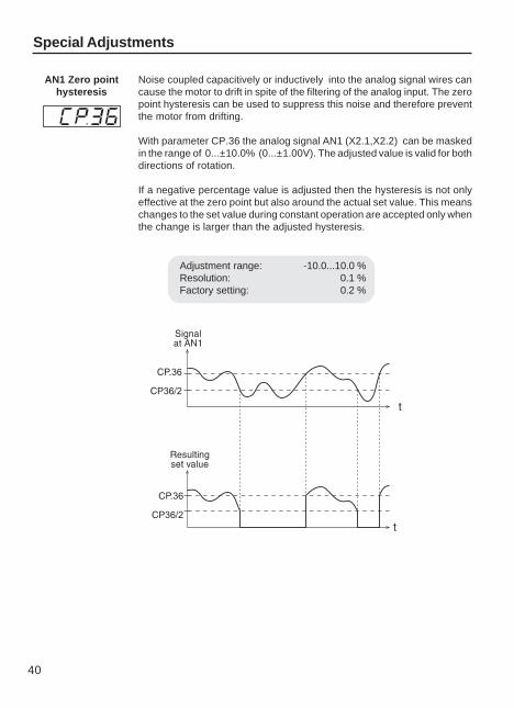
Adjustment range: -10.0...10.0 %Resolution: 0.1 %Factory setting: 0.2 %
AN1 Zero pointhysteresis
Noise coupled capacitively or inductively into the analog signal wires cancause the motor to drift in spite of the filtering of the analog input. The zeropoint hysteresis can be used to suppress this noise and therefore preventthe motor from drifting.
With parameter CP.36 the analog signal AN1 (X2.1,X2.2) can be maskedin the range of 0...±10.0% (0...±1.00V). The adjusted value is valid for bothdirections of rotation.
If a negative percentage value is adjusted then the hysteresis is not onlyeffective at the zero point but also around the actual set value. This meanschanges to the set value during constant operation are accepted only whenthe change is larger than the adjusted hysteresis.
Special Adjustments
!"#"!$#!
%
%
41
Drive Mode
4.7 The "Drive Mode"
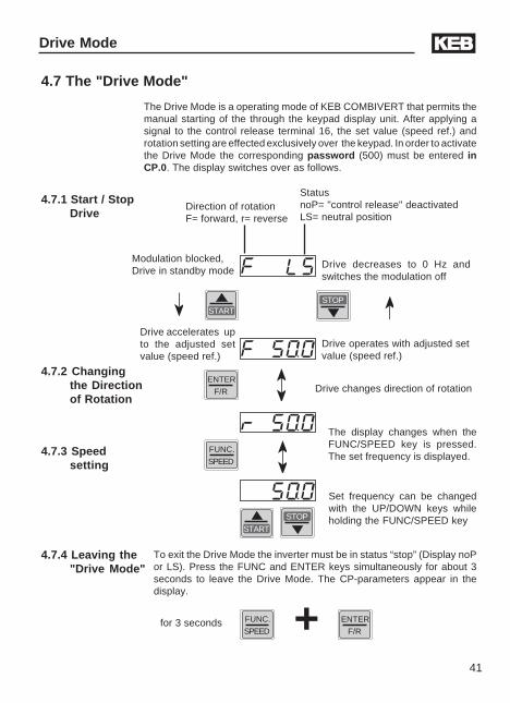
The Drive Mode is a operating mode of KEB COMBIVERT that permits themanual starting of the through the keypad display unit. After applying asignal to the control release terminal 16, the set value (speed ref.) androtation setting are effected exclusively over the keypad. In order to activatethe Drive Mode the corresponding password (500) must be entered inCP.0. The display switches over as follows.
Direction of rotationF= forward, r= reverse
StatusnoP= "control release" deactivatedLS= neutral position
Set frequency can be changedwith the UP/DOWN keys whileholding the FUNC/SPEED key
4.7.1 Start / StopDrive
4.7.3 Speedsetting
4.7.2 Changingthe Directionof Rotation
FUNC.
SPEED
STOPSTART
ENTER
F/R
To exit the Drive Mode the inverter must be in status “stop” (Display noPor LS). Press the FUNC and ENTER keys simultaneously for about 3seconds to leave the Drive Mode. The CP-parameters appear in thedisplay.
4.7.4 Leaving the"Drive Mode"
START
STOP
Modulation blocked,Drive in standby mode
Drive decreases to 0 Hz andswitches the modulation off
Drive accelerates upto the adjusted setvalue (speed ref.)
Drive operates with adjusted setvalue (speed ref.)
Drive changes direction of rotation
The display changes when theFUNC/SPEED key is pressed.The set frequency is displayed.
FUNC.
SPEED + ENTER
F/Rfor 3 seconds
46
6. Quick Reference
Display Parameter Adjust. range Resolution Cust. setting
CP. 0 Password input 0...9999 1 read only
CP. 1 Actual frequency display – 0.0125 Hz read only
CP. 2 Set frequency display – 0.0125 Hz read only
CP. 3 Inverter status display – – read only
CP. 4 Phase current – 0.1 A read only
CP. 5 Phase current, Peak value – 0.1 A read only
CP. 6 Actual load – 1 % read only
CP. 7 Actual DC voltage – 1 V read only
CP. 8 Actual DC voltage, Peak value – 1 V read only
CP. 9 Output voltage – 1 V read only
CP.10 Minimum frequency 0…400 Hz 0.0125 Hz ___________
CP.11 Maximum frequency 0…400 Hz 0.0125 Hz ___________
CP.12 Acceleration time 0.01…300.00 s 0.01 s ___________
CP.13 Deceleration time(-1 see CP.12) -1; 0.01…300.00 s 0.01 s ___________
CP.14 S-curve time 0.00 (off)…5.00 s 0.01 s ___________
CP.15 Torque boost 0.0…25.5 % 0.1 % ___________
CP.16 Rated frequency 0…400 Hz 0.0125 Hz ___________
CP.17 1) Voltage stabilization 1…650 V (off) 1 V ___________
CP.18 1) Carrier frequency 2/4/8/12/16 kHz – ___________
CP.19 Fixed frequency 1 -400...400 Hz 0.0125 Hz ___________
CP.20 Fixed frequency 2 -400...400 Hz 0.0125 Hz ___________
CP.21 Fixed frequency 3 -400...400 Hz 0.0125 Hz ___________
CP.22 1) DC-braking, Mode 0…9 1 ___________
CP.23 DC-braking, Time 0.00…100.00 s 0.01 s ___________
CP.24 Max. ramp current 0…200 % 1 % ___________
CP.25 Max. constant current 0…200 % (off) 1 % ___________
CP.26 1) Speed search condition 0…15 1 ___________
CP.27 Quick stop time 0.00…300.00 s 0.01 s ___________
CP.28 Response of ext. overtemperature 0…7 1 ___________
CP.29 1) Analog output 1 0…12...20 F5G 1 ___________
CP.30 Analog output 1, Amplification -20.00…20.00 0.01 ___________
CP.31 1) Relay output 1 0…58...66 F5B 1 ___________
CP.32 1) Relay output 2 0…58...66 F5B 1 ___________
CP.33 Relay output 2, Switching level ±30000.00 0.01 ___________
CP.34 1) Source of rotation direction 0…9 1 ___________
CP.35 1) AN1 interface selection 0…2 1 ___________
CP.36 AN1 zero point hysteresis -10.0…10.0 % 0.1 % ___________
47
When switching on the KEB COMBIVERT F5, the value of parameter CP.1appears in the operator display. (see "Drive Mode" to switch the keypadfunction)
The function key (FUNC) changes between the parameter value andparameter number.
With UP and DOWN, the value of the parameter number is increased/decreased.
Password Input
FUNC.
SPEED
START
FUNC.
SPEED
ENTER
F/R
FUNC.
SPEED
START
FUNC.
SPEED
ENTER
F/R
Releasing theCP-Parameters
Locking theCP-Parameters(Read only)
From the factory, the frequency inverter is supplied withoutpassword protection, this means that all parameters can beadjusted. After programming, the unit can be protected againstunauthorized access thus preventing the values from beingchanged.
Quick Reference
Parameter Display
FUNC.
SPEED
STARTSTOP
STARTSTOP

48
Notes

49
Notes

50
Notes
You can find supplementary manuals and intructions which can be downloaded from
www.kebco.com
General instructions• Part 1 EMC-and safety instructions for CE instalations (Must be supplied when unit isshipped to Europe)
Unit-specific instructions• Part 2 Power Circuit for complete power range• Part 3 Control Circuit for B/G, M, or S version
Service notes• Up/Download of parameter lists with KEB COMBIVERT• Error messages
Detailed Instructions and information for application design and development• Application Manual• Preparation of a user-defined parameter menu• Programming of the digital inputs
All documents are also available in printed version, please contact your local sales office.Some of the above doucmentation is free while some of it must be purchased.
© K
EB
00.F
5.0U
M-K
B01
03/2
004
Karl E. Brinkmann GmbHFörsterweg 36 - 38 • D - 32683 Barntrup
Telefon 00 49 / 52 63 / 4 01 - 0 • Fax 00 49 / 52 63 / 4 01 - 1 16Internet: www.keb.de • E-mail: [email protected]
KEB Antriebstechnik GmbH & Co. KGWildbacher Str. 5 • D - 08289 Schneeberg
Telefon 0049 / 37 72 / 67 - 0 • Telefax 0049 / 37 72 /67 - 2 81E-mail: [email protected]
KEB Antriebstechnik Austria GmbHRitzstraße 8 • A - 4614 Marchtrenk
Tel.: 0043 / 7243 / 53586 - 0 • FAX: 0043 / 7243 / 53586 - 21Kostelni 32/1226 • CZ - 370 04 Ceské Budejovice
Tel.: 00420 / 38 / 731 92 23 • FAX: 00420 / 38 / 733 06 97E-mail: [email protected]
KEB AntriebstechnikHerenveld 2 • B - 9500 Geraadsbergen
Tel.: 0032 / 5443 / 7860 • FAX: 0032 / 5443 / 7898E-mail: [email protected]
KEB ChinaXianxia Road 299 • CHN - 200051 Shanghai
Tel.: 0086 / 21 / 62350922 • FAX: 0086 / 21 / 62350015Internet: www.keb-cn.com • E-mail: [email protected]
Société Française KEBZ.I. de la Croix St. Nicolas • 14, rue Gustave Eiffel
F - 94510 LA QUEUE EN BRIETél.: 0033 / 1 / 49620101 • FAX: 0033 / 1 / 45767495
E-mail: [email protected]
KEB (UK) Ltd.6 Chieftain Buisiness Park, Morris Close
Park Farm, Wellingborough, GB - Northants, NN8 6 XFTel.: 0044 / 1933 / 402220 • FAX: 0044 / 1933 / 400724Internet: www.keb-uk.co.uk • E-mail: [email protected]
KEB Italia S.r.l.Via Newton, 2 • I - 20019 Settimo Milanese (Milano)
Tel.: 0039 / 02 / 33500782 • FAX: 0039 / 02 / 33500790Internet: www.keb.it • E-mail: [email protected]
KEB - YAMAKYU Ltd.711 Fukudayama, Fukuda
J - Shinjo-Shi, Yamagata 996 - 0053Tel.: 0081 / 233 / 29 / 2800 • FAX: 0081 / 233 / 29 / 2802
E-mail: [email protected]
KEB PortugalLugar de Salgueiros – Pavilhao A, Mouquim
P - 4760 V. N. de FamalicaoTel.: 00351 / 252 / 371 318 • FAX: 00351 / 252 / 371 320
E-mail: [email protected]
KEB Taiwan Ltd.1F, No.19-5, Shi Chou Rd., Tounan Town
R.O.C. - Yin-Lin Hsian / TaiwanTel.: 00886 / 5 / 5964242 • FAX: 00886 / 5 / 5964240
E-mail: [email protected]
KEBCO Inc.1335 Mendota Heights Road
USA - Mendota Heights, MN 55120Tel.: 1-651-454-6162 • FAX: 1-651-454-6198
Internet: www.kebco.com • E-mail: [email protected]


![a fu titel gb - Electrónica Indústrialelectronicaindustrial.pt/application/uploads/files/00f5bemka02[1].pdf · 2 This manual describes the KEB COMBIVERT F5. Particular attention](https://img.pdfslide.us/doc/110x75/5b4310417f8b9ab15f8baa97/a-fu-titel-gb-electronica-industriale-1pdf-2-this-manual-describes-the.jpg)