Embed Size (px)
Citation preview
Stirrers
Hotplates
Instruction ManualAdvanced Series
Hotplate-Stirrers
Revision 2/10

PACKAGE CONTENTS
- Hotplate, Stirrer or Hotplate-Stirrer- 234cm detachable power cord- Spin bar (stirring models only)- Instruction manual
WARRANTY
VWR International warrants that this product will be free from defects in material and workmanshipfor a period of two (2) years from date of purchase. If a defect is present, VWR will, at its option,repair, replace, or refund the purchase price of this product at no charge to you, provided it isreturned during the warranty period. This warranty does not apply if the product has been damagedby accident, abuse, misuse, or misapplication, or from ordinary wear and tear.For your protection,items being returned must be insured against possible damage or loss. This warranty shall be lim-ited to the replacement of defective products. IT IS EXPRESSLY AGREED THAT THIS WARRANTY WILLBE IN LIEU OF ALL WARRANTIES OF FITNESS AND IN LIEU OF THE WARRANTY OF MERCHANTABILITY.
TABLE OF CONTENTSPackage Contents . . . . . . . . . . . . . . . 1Warranty . . . . . . . . . . . . . . . 1Installation . . . . . . . . . . . . . . . 2Maintenance & Servicing . . . . . . . . . . . . . . . 2Intended Use . . . . . . . . . . . . . . . 2Equipment Disposal . . . . . . . . . . . . . . . 2Environmental Conditions . . . . . . . . . . . . . . . 2Safety Instructions . . . . . . . . . . . . . . . 3Standards & Regulations . . . . . . . . . . . . . . . 310 x 10 Specifications . . . . . . . . . . . . . . . 418 x 18 Specifications . . . . . . . . . . . . . . . 525 x 25 Specifications . . . . . . . . . . . . . . . 6Heating Operating Instructions . . . . . . . . . . . . . . . 7-9Stirring Operating Instructions . . . . . . . . . . . . . . . 10Technical Service . . . . . . . . . . . . . . . 11Troubleshooting . . . . . . . . . . . . . . . 11Replacement Parts . . . . . . . . . . . . . . . 12-14
1

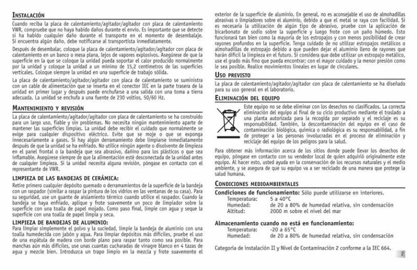
INSTALLATIONUpon receiving the VWR Hotplate/Stirrer/Hotplate-Stirrer, check to ensure thatno damage has occurred in shipment. It is important that any damage thatoccurred in transport is detected at the time of unpacking. If you do find suchdamage the carrier must be notified immediately.After unpacking, place the Hotplate/Stirrer/Hotplate-Stirrer on a level bench ortable, away from explosive vapors. Ensure that the surface on which the unit isplaced will withstand typical heat produced by the unit and place the unit a min-imum of 15,2 centimeters from vertical surfaces. Always place the unit on a stur-dy work surface.The Hotplate/Stirrer/Hotplate-Stirrer is supplied with a power cord that is insert-ed into the IEC connector on the back of the unit first, then it can be pluggedinto a properly grounded outlet. The unit plugs into a 230 volt, 50/60 Hz source.
MAINTENANCE & SERVICINGThe Hotplate/Stirrer/Hotplate-Stirrer is built for long, trouble-free, dependableservice. It needs no user maintenance beyond keeping the surfaces clean. Theunit should be given the care normally required for any electrical appliance. Avoidwetting or unnecessary exposure to fumes. Spills should be removed promptlyafter the unit has cooled down. Do not use a cleaning agent or solvent on thefront panel or top plate which is abrasive or harmful to plastics, nor one whichis flammable. Always ensure the power is disconnected from the unit prior to anycleaning. If the unit ever requires service, contact your VWR representative.
CLEANING CERAMIC TOPS:First remove any burnt-on deposits or spills from the top plate with a scraper(similar to scraping paint off of windowpanes in your home). For your safety,please wear an insulated mit when using a metal scraper. When the top plate hascooled, apply a few dabs of a non-abrasive cleaner over the surface with a damppaper towel. As a final step, clean with water and wipe surface with a clean, drypaper towel.CLEANING ALUMINIUM TOPS:For simple dust and dirt, clean the aluminium top by using a damp cloth withsoap and water. For more stubborn deposits, try using a flat edge wooden spat-ula to scrape off as much as possible. For more stubborn stains, try using a cou-ple of tablespoons of white vinegar to two pints of water and mix well. Dip aclean cloth into the mixture and gently rub the exterior of the aluminium sur-face. Generally, it is not a good idea to use abrasive pads or cleaners on aluminium,
as the metal will scratch easily. If you must use some type of abrasive, try apply-ing baking soda to the surface and then rubbing with a moist cloth. This willwork as well as most scouring pads and is less likely to create deep scratches inthe surface. Be careful not to use steel wool or scouring pads as they can leavethe aluminium riddled with little scratches that make it harder to clean in thefuture. If you feel you must use steel wool, use the finest grade you can findand use as sparingly as possible with as little pressure as possible. Go with thegrain rather than using circular motions.
INTENDED USEThese Hotplate/Stirrers/Hotplate-Stirrers are intended for general laboratory use.
EQUIPMENT DISPOSALThis equipment must not be disposed of with unsorted waste. It isyour responsibility to correctly dispose of the equipment at life-cycle-end by handing it over to an authorized facility for separate collec-tion and recycling. It is also your responsibility to decontaminate theequipment in case of biological, chemical and/or radiological contam-ination, so as to protect the persons involved in the disposal and
recycling of the equipment from health hazards.
For more information about where you can drop off your waste of equipment,please contact your local dealer from whom you originally purchased this equip-ment. By doing so, you will help to conserve natural and environmental resourcesand you will ensure that your equipment is recycled in a manner that protectshuman health.
ENVIRONMENTAL CONDITIONSOperating Conditions: Indoor use only.
Temperature: 5 to 40°CHumidity: 20% to 80% relative humidity, non-condensingAltitude: 2000 M above sea level
Non-Operating Storage:Temperature: -20 to 65°CHumidity: 20% to 80% relative humidity, non-condensing
Installation Category II and Pollution Degree 2 in accordance with IEC 664.
2

SAFETY INSTRUCTIONSPlease read the entire instruction manual before operating the Hotplate/Stirrer/Hotplate-Stirrer.
WARNING! DO NOT use the Hotplate/Stirrer/Hotplate-Stirrer in ahazardous atmosphere or with hazardous materials for which the unitwas not designed. Also, the user should be aware that the protectionprovided by the equipment may be impaired if used with accessoriesnot provided or recommended by the manufacturer, or used in a mannernot specified by the manufacturer.
Always operate unit on a level surface for best performance and maximumsafety.
DO NOT lift unit by the top plate.
CAUTION! To avoid electrical shock, completely cut off power to theunit by disconnecting the power cord from the unit or unplug from thewall outlet. Disconnect unit from the power supply prior to maintenanceand servicing.
Spills should be removed promptly after the unit has cooled down.DO NOT immerse the unit for cleaning. Alkalis spills, hydrofluoric acidor phosphoric acid spills may damage the unit and lead to thermalfailure.
CAUTION! The top plate can reach 500°C, DO NOT touch the heatedsurface. Use caution at all times. Keep the unit away from explosivevapors and clear of papers, drapery and other flammable materials.Keep the power cord away from the heater plate.
DO NOT operate the unit at high temperatures without a vessel/sampleon the top plate.
WARNING! Units are NOT explosion proof. Use caution when heatingvolatile materials.
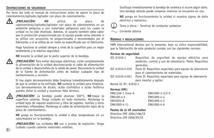
Replace the ceramic top immediately if damaged. A damaged top canbreak in use.
DO NOT operate the unit if it shows signs of electrical of mechanicaldamage.
Earth Ground - Protective Conductor Terminal
Alternating Current
STANDARDS & REGULATIONSVWR International hereby declares under it's sole responsibility that the con-struction of this product conforms in accordance with the followingstandards:
Safety standards:IEC 61010-1 Safety requirements for electrical equipment for measure-
ment, control and laboratory use. Part: GeneralRequirements.
IEC 61010-2-010 Part II: Particular requirements for laboratory equipmentfor the heating of materials.
IEC 61010-2-051 Part II: Particular requirements for laboratory equipmentfor mixing and stirring.
UL Std. No. 61010-1
EMC standards:EN61326-1 Class A EN61000-3-3/3-2EN6100-4-5 EN61000-4-4EN55022-B EN61000-4-3EN61000-4-11 EN61000-4-6
Associated EU guidelines:EMC directive 2004/108/ECLVD directive 2006/95/EC
3
�
�

10 X 10 HOTPLATE/STIRRER/HOTPLATE-STIRRER SPECIFICATIONSDimensions (L x W x H): 27,4 x 16,7 x 10,8cm
Top plate dimensions (L x W): 10,2 x 10,2cm
Electrical (50/60 Hz):Hotplate Stirrer Hotplate-Stirrer
1,5 amps/350 watts 0,2 amps/50 watts 1,7 amps/400 watts
Fuses: 5mm x 20mm, 5 amp quick acting
Temperature range:ceramic: ambient +5°C to 500°Caluminium: ambient +5°C to 400°C
Temperature stability: ceramic*: +/-3%aluminium*: +/-2%
Speed range: 60 to 1600rpmSpeed stability: +/-2%
Capacity: 600ml, gross weight should not exceed 9kg
Controls: see diagrams
Ship weight: 2,8kg
* Below 100°C +/-2°C. Environmental and sample conditions permitting.
NOTE: On Advanced units, the max. temperature setting on the display is500°C for a ceramic top and 400°C for an aluminium top.
ADVANCED SERIES 10 X 10
4
heat adjust knob
stir adjust knob
caution hot topindicator light
recall last temp. button
temperature display
Plug Stirrer - Ceramic Hotplate - Ceramic Hotplate-Stirrer - CeramicEU 444-0566 444-0575 444-0593UK 444-0567 444-0576 444-0594CH 444-0568 444-0577 444-0595Plug Hotplate - Aluminium Hotplate-Stirrer - AluminiumEU 444-0578 444-0596UK 444-0579 444-0597CH 444-0580 444-0598
VWR Advanced Series 10 x 10,Ceramic Hotplate-Stirrer

5
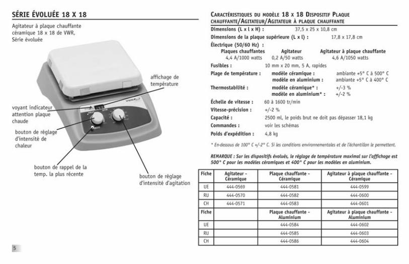
18 X 18 HOTPLATE/STIRRER/HOTPLATE-STIRRER SPECIFICATIONSDimensions (L x W x H): 37,5 x 25 x 10,8cm
Top plate dimensions (L x W): 17,8 x 17,8cm
Electrical (50/60 Hz):Hotplate Stirrer Hotplate-Stirrer
4,4 amps/1000 watts 0,2 amps/50 watts 4,6 amps/1050 watts
Fuses: HP / HPS 5mm x 20mm, 16 amp slow blowStirrer 5mm x 20mm, 5 quick acting
Temperature range: ceramic: ambient +5°C to 500°Caluminium: ambient +5°C to 400°C
Temperature stability: ceramic*: +/-3%aluminium*: +/-2%
Speed range: 60 to 1600rpmSpeed stability: +/-2%
Capacity: 2500ml, gross weight should not exceed 18,1kg
Controls: see diagrams
Ship weight: 4,8kg
* Below 100°C +/-2°C. Environmental and sample conditions permitting.
NOTE: On Advanced units, the max. temperature setting on the display is500°C for a ceramic top and 400°C for an aluminium top.
heat adjust knob
stir adjust knob
caution hot topindicator light
recall last temp. button
temperature display
ADVANCED SERIES 18 X 18
Plug Stirrer - Ceramic Hotplate - Ceramic Hotplate-Stirrer - CeramicEU 444-0569 444-0581 444-0599UK 444-0570 444-0582 444-0600CH 444-0571 444-0583 444-0601Plug Hotplate - Aluminium Hotplate-Stirrer - AluminiumEU 444-0584 444-0602UK 444-0585 444-0603CH 444-0586 444-0604
VWR Advanced Series 18 x 18,Ceramic Hotplate-Stirrer

6
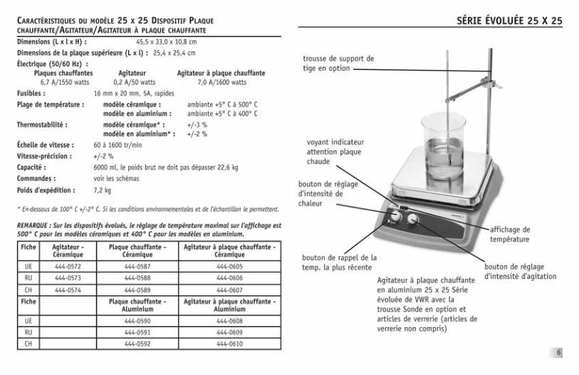
25 X 25 HOTPLATE/STIRRER/HOTPLATE-STIRRER SPECIFICATIONSDimensions (L x W x H): 45,5 x 33,0 x 10,8cm
Top plate dimensions (L x W): 25,4 x 25,4cm
Electrical (50/60 Hz):Hotplate Stirrer Hotplate-Stirrer
6,7 amps/1550 watts 0,2 amps/50 watts 7,0 amps/1600 watts
Fuses: HP / HPS 5mm x 20mm, 16 amp slow blowStirrer 5mm x 20mm, 5 quick acting
Temperature range: ceramic: ambient +5°C to 500°Caluminium: ambient +5°C to 400°C
Temperature stability: ceramic*: +/-3%aluminium*: +/-2%
Speed range: 60 to 1600rpmSpeed stability: +/-2%
Capacity: 6000ml, gross weight should not exceed 22,6kg
Controls: see diagrams
Ship weight: 7,2kg
* Below 100°C +/-2°C. Environmental and sample conditions permitting.
NOTE: On Advanced units, the max. temperature setting on the display is500°C for a ceramic top and 400°C for an aluminium top.
heat adjust knob
stir adjust knob
caution hot topindicator light
recall last temp. button
temperature display
optional supportrod kit
ADVANCED SERIES 25 X 25
Plug Stirrer - Ceramic Hotplate - Ceramic Hotplate-Stirrer - CeramicEU 444-0572 444-0587 444-0605UK 444-0573 444-0588 444-0606CH 444-0574 444-0589 444-0607Plug Hotplate - Aluminium Hotplate-Stirrer - AluminiumEU 444-0590 444-0608UK 444-0591 444-0609CH 444-0592 444-0610
VWR Advanced Series 25 x 25,Aluminium Hotplate-Stirrerwith optional Probe Kit andglassware (glassware notincluded)

HEATING OPERATING INSTRUCTIONSThe Hotplates and Hotplate-Stirrers have a micro-processor controlled heaterthat is designed to bring samples to temperature quickly and accurately.
1. Getting ready:a. Turn the heat knob to the off position. Plug power cord into a properly
grounded 3-prong outlet.b. Place a vessel with solution and the appropriate accessories in the
center of the top plate. This is important because the vessel shouldbe over the hottest part of the top plate.
2. Setting temperature for Advanced Series :a. Turn the heat knob clockwise until the display reaches the desired heat
setting. The display will flash the set-point temperature until the tem-perature is reached, at which time the display will stopflashing. Whenthe heat is turned on the indicator light above the heat knob is illu-minated. Removing or adding more to a sample content could causethe temperature to fluctuate. If this occurs, the display will againstartto flash until the set-point value is stabilized.
b. Temperature adjustments can be made without interrupting heatingby turning the heat knob clockwise to increase heat or counter-clockwise to decrease heat.
c. To stop heating, turn the heat knob to the off position. Your vesselcan then be removed.
Caution hot top indicator:The caution hot top indicator light warns thatthe top plate is too hot to touch. The cautionhot top indicator light will illuminate whenthe heat is turned on and remain on until the top plate cools down.
Recall last temperature button:Advanced Series Hotplate/Hotplate-Stirrers have a built-in memory thatallows users to recall the last set temperature, even after the unit has beenturned off. (The temperature in memory is the last temperature that ran formore than 5 minutes.)Max Temperature:If the unit has an aluminium top, the max temperature setting is 400°C. Ifthe unit has a ceramic top, the max temperature setting is 500°C.
OPERATING TIPSThe unit may overshoot the temperature up to 10°C before stabilizing at theset-point. The two methods suggested to minimize overshoot are:
1. Metal containers minimize overshoot. CAUTION: When heating metalcontainers on a ceramic top it is recommended to use the lowesttemperature setting possible to limit thermal stress to the ceramic top.
2. If a glass vessel is used, anticipate overshoot. Start with a setting 5-10°Cbelow the desired temperature. When the temperature stabilizes atthis lower setting, turn the heat knob to the final temperature.Overshoot is then reduced to about 1°C.
The temperature display on the advanced units show the actual temperatureof the heater not the top plate or sample. The vessel contents being heatedmay be at a lower temperature depending on the size and insulating qualitiesof the vessel. It may be beneficial to monitor the temperature of the vesselcontents and adjust the set-point temperature accordingly.
7
8
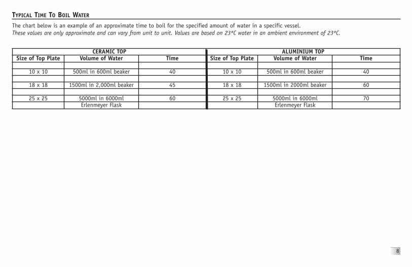
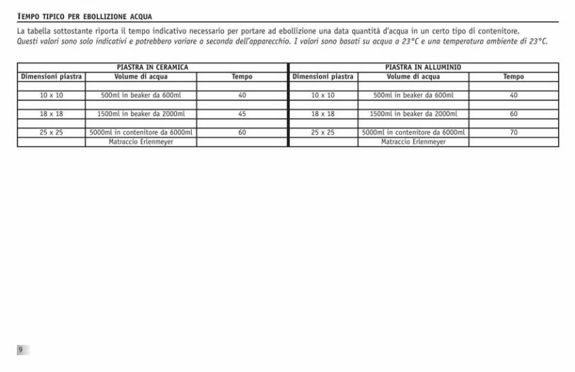
TYPICAL TIME TO BOIL WATERThe chart below is an example of an approximate time to boil for the specified amount of water in a specific vessel.These values are only approximate and can vary from unit to unit. Values are based on 23ºC water in an ambient environment of 23ºC.
CERAMIC TOP ALUMINIUM TOPSize of Top Plate Volume of Water Time Size of Top Plate Volume of Water Time
10 x 10 500ml in 600ml beaker 40 10 x 10 500ml in 600ml beaker 40
18 x 18 1500ml in 2,000ml beaker 45 18 x 18 1500ml in 2000ml beaker 60
25 x 25 5000ml in 6000ml 60 25 x 25 5000ml in 6000ml 70Erlenmeyer Flask Erlenmeyer Flask

9
TEMPERATURE CALIBRATION PROCEDURE (SINGLE POINT CALIBRATION, ADVANCED SERIES)This method can be used for calibrating the top plate surface of the Advanced Seriesunit.To set a Single Point Calibration (SPC) adjustment:
a. Turn the heat knob clockwise until the display reaches the desired heatsetting, and let the unit stabilize to the user input temperature. Theheater temperature has stabilized when the temperature display is nolonger blinking and the unit will beep five times.
b. Wait ten minutes for the surface temperature to stabilize. Measure thetop plate with a traceable surface temperature measuring device.
c. Press and hold the Last Temperature button. The display will start toscroll through the available SPC options (“UP”, “dn”, “SEt” and “dEL”) aslong as the Last Temperature button is held down. Once you select “UP”or “dn” mode and release the Last Temperature button the unit will beeptwo times and the display will begin to blink quickly. This lets you knowyou are programming in SPC mode.
NOTE: There is a thirty second time out (Last Temperature button must bepressed at least once in thirty seconds, or unit will exit SPC mode). Do nottouch the heat knob while in SPC mode. If the heat knob is adjusted dur-ing this procedure you will exit SPC mode.
d. Once the desired option is displayed, release the Last Temperature button.Please see the explanation below for each option.
e. Selecting the “SEt” option saves the Single Point Calibration adjustmentfor that temperature set point and allows you to exit this SPC mode (seeSection c). When the “Set” option is selected “SEt” will be displayed. Tosave the current SPC point and exit the SPC programming mode, releasethe Last Temperature button when “SEt” is on the display. The display willnow show your set point temperature with a decimal point for that set-ting.
f. Select the “UP” option if your externally measured temperature of the topplate is higher than the set point on the display. When the “UP” optionis selected the current SPC adjusted temperature is displayed and blink-
ing quickly. To increase the SPC, press and release the LastTemperature button multiple times (do not touch heat knob) until thedisplay reads the value you recorded as the measured temperature of thetop plate. Changes are not saved until the “SEt” option is selected (andthe Last Temperature button is pressed and released), if the temperatureis adjusted too high, delete the SPC adjustment and repeat procedure.
g. Select the “dn” option if your externally measured temperature of the topplate is lower than the set point on the display. When the “dn” optionis selected the current SPC adjusted temperature will be displayed andblinking quickly. To decrease the SPC, press and release the LastTemperature button multiple times (do not touch the heat knob) untilthe display reads the value you recorded as the measured temperature ofthe top plate. Changes are not saved until the “SEt” option is selected(and the Last Temperature button is pressed and released), if the temper-ature is adjusted too low, delete the SPC adjustment and repeat procedure.
h. Selecting the “dEL” option will delete all Single Point Calibration pointsand allow you to exit this SPC mode (see Section c). When the “dEL”option is selected “dEL” will be displayed. To delete all SPC points andexit the SPC mode release the Last Temperature button when “dEL” is onthe display.
i. For set point temperatures with a SPC adjustment, there will be a decimalpoint in the display. Once the SPC adjustment is set, the display will blinkwhile the unit’s temperature is settling. When the SPC set point isreached, the display will stop blinking and the unit will beep five times.
j. This process may be repeated for up to three separate set points. If afourth SPC set point is entered, the first set point will be overwritten. Toreadjust an existing SPC set point, you must delete the current settings(all SPC points will be deleted, and the decimal points will no longer bedisplayed at those temperatures) and repeat the SPC procedure. If SPCadjustments are not deleted prior to resetting SPC for a set point thenthe temperature adjustment will not be accurate
k. The SPC adjustments are limited to the maximum and minimum tempera-tures and limits allowed by the particular unit.

The micro-processor controlled ramping feature slowly increases speed untilthe set-point is reached. This feature helps to avoid splashing, improvesmagnetic coupling and provides excellent low end control. The micro-proces-sor also monitors and regulates the stirring speed, sensing your requirementswhether you're stirring an aqueous, viscous or semi-solid solution.
Initial stirring speed may exceed set speed if the following conditions exist:1. The stirrer is set at a low speed and the stirrer has not been operated for
a extended period of time.2. The stirrer is set at a low speed and it is the stirrer's initial use.
1. Getting ready:a. Turn stir knob to the off position. Plug power cord into a properly
grounded outlet.b. Place a vessel with solution and the appropriate spin bar in the
center of the top plate.
2. Setting speed:a. Turn the stir knob clockwise until the pointer reaches the desired speed
setting. The stir indicator light above the stir knob will illuminate toindicate the stirring feature is in use. The stir indicator light will blinkwhile reaching the set-point. Once the set-point is reached the lightwill remain lit.
b. Speed adjustments can be made without interrupting stirring byturning the stir knob clockwise to increase speed, or counter-clockwiseto decrease speed.
c. To stop stirring, turn the stir knob to the off position. Your vesselcan then be removed.
Stir protection for Hotplate-Stirrers:If stirrer motor stops or fails, the unit will automatically shut downthe heater.
OPERATING TIPSThe stirrer increases speed at a steady rate until the set-point is reached, ifthe stir bar is too large or the liquid is too viscous, the stirrer may not reachits set-point. The set-point speed needs to be reduced. The magneticstrength of stir bars reduce over time and may need to be replaced.Stirring vessels in oil baths:
When heating and stirring a reaction vessel within an oil bath or similarset-up, the stirring function will stir up to approximately 2,54cmfrom the top plate. The stirring speed will vary according to liquidviscosity, stir bar length and distance from the top plate. Adjust oneor all of these to achieve the desired stirring speed.
EXAMPLE: The closer the reaction vessel is to the top plate the strongerthe magnetic connection.
STIRRING OPERATING INSTRUCTIONS
10

11
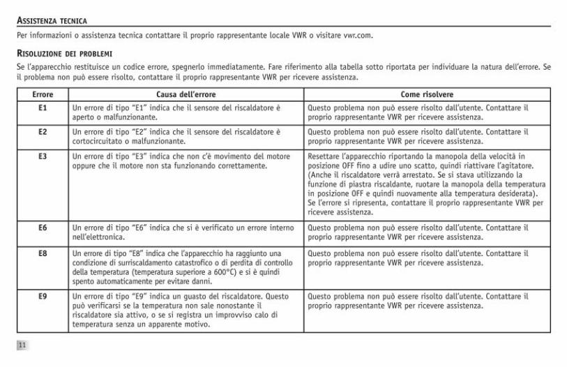
If the unit gives an error code, immediately switch the unit off. See error table below for proper corrective action. If the error cannot be cleared, please con-tact your VWR representative for repairs.
TROUBLESHOOTING
Error Cause of Error How to Fix
E1 An “E1” error means the heater sensor is open or malfunctioned. This error cannot be fixed by the end user. Please contact your VWRrepresentative for repair.
E2 An “E2” error means the heater sensor shorted or malfunctioned. This error cannot be fixed by the end user. Please contact your VWRrepresentative for repair.
E3 An “E3” error means there is either no motion on the motor or themotor is not working properly.
Reset the unit by rotating the knob for speed to the off position untilit clicks then turn it back on. (Also the heater will shut off. If youwere heating, rotate the knob for heat to the off position then backon again if you were heating). If it still doesn’t work, please contactyour VWR representative for repair.
E6 An “E6” error means there is an internal electronics system error. This error cannot be fixed by the end user. Please contact your VWRrepresentative for repair.
E8 An "E8" error means the unit had a catastrophic over temperaturecondition or temperature runaway condition (temperature greater than600°C) and therefore automatically shut down to prevent damage.
This error cannot be fixed by the end user. Please contact your VWRrepresentative for repair.
E9 An “E9” error means the heater failed. This might occur if heatertemperature fails to rise when asked to, or there is a sudden dropin heater temperature for no apparent reason.
This error cannot be fixed by the end user. Please contact your VWRrepresentative for repair.
TECHNICAL SERVICEFor information or technical assistance contact your local VWR representative or visit vwr.com.

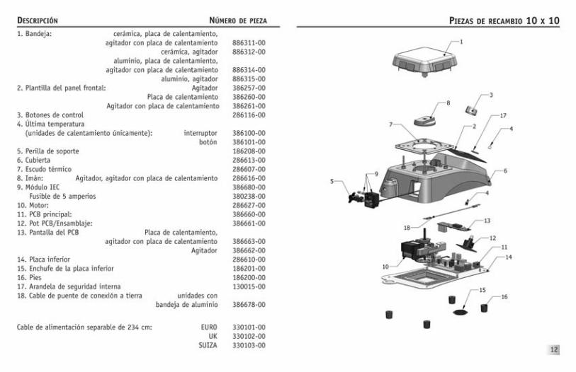
DESCRIPTION PART NUMBER1. Top plate assembly: ceramic, Hotplate, Hotplate-Stirrer 886311-00
ceramic, Stirrer 886312-00aluminium, Hotplate, Hotplate-Stirrer 886314-00
aluminium, Stirrer 886315-002. Front panel overlay: Stirrer 386257-00
Hotplate 386260-00Hotplate-Stirrer 386261-00
3. Control knobs 286116-004. Last temperature (Heating Units only): switch 386100-00
button 386101-005. Support stand thumb knob 186208-006. Housing 286613-007. Heat Shield 286607-008. Magnet assembly: Stirrer, Hotplate-Stirrer 286616-009. IEC module 386680-00
Fuse 5 amp 380238-0010. Motor: 286627-0011. Main PCB: 386660-0012. Pot PCB/Assy: 386661-0013. Display PCB Hotplate, Hotplate-Stirrer 386663-00
Stirrer 386662-0014. Bottom Plate 286610-0015. Bottom Plate plug 186201-0016. Feet 186200-0017. Internal Lock Washer 130015-0018. Ground Jumper Wire aluminium top units 386678-00
Detachable 234cm Power Cord: EURO 330101-00UK 330102-00
SWISS 330103-00
10 X 10 REPLACEMENT PARTS
12

13
18 X 18 REPLACEMENT PARTS DESCRIPTION PART NUMBER1. Top plate assembly: ceramic, Hotplate, Hotplate-Stirrer 886317-00
ceramic, Stirrer 886318-00aluminium, Hotplate, Hotplate-Stirrer 886320-00
aluminium, Stirrer 886321-002. Front panel overlay: Stirrer 386262-00
Hotplate 386265-00Hotplate-Stirrer 386266-00
3. Control knobs 286116-004. Last temperature (Heating Units only): switch 386104-00
button 386101-005. Support stand thumb knob 186208-006. Housing 286614-007. Heat Shield 286608-008. Magnet assembly: Stirrer, Hotplate-Stirrer 286616-009. IEC module 386681-00
Fuse 10 Amp 386005-0010. Motor: 286627-0011. Main PCB: Hotplate 386660-0012. Pot PCB/Assy: 386661-0013. Display PCB Hotplate, Hotplate-Stirrer 386663-00
Stirrer 386662-0014. Bottom Plate 386611-0015. Bottom Plate plug 186201-0016. Feet 186200-0017. Internal Lock Washer 130015-0018. Ground Jumper Wire aluminium top units 386678-00
Detachable 234cm Power Cord: EURO 330101-00UK 330102-00
SWISS 330103-00

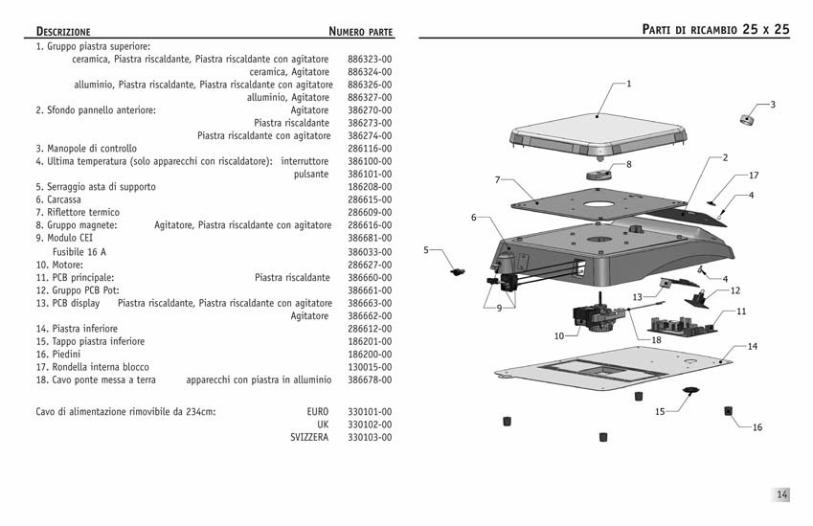
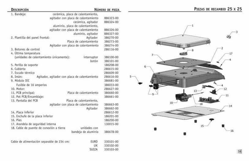
25 X 25 REPLACEMENT PARTSDESCRIPTION PART NUMBER1. Top plate assembly: ceramic, Hotplate, Hotplate-Stirrer 886323-00
ceramic, Stirrer 886324-00aluminium, Hotplate, Hotplate-Stirrer 886326-00
aluminium, Stirrer 886327-002. Front panel overlay: Stirrer 386270-00
Hotplate 386273-00Hotplate-Stirrer 386274-00
3. Control knobs 286116-004. Last temperature (Heating Units only): switch 386100-00
button 386101-005. Support stand thumb knob 186208-006. Housing 286615-007. Heat Shield 286609-008. Magnet assembly: Stirrer, Hotplate-Stirrer 286616-009. IEC module 386681-00
Fuse 16 Amp 386033-0010. Motor: 286627-0011. Main PCB: Hotplate 386660-0012. Pot PCB/Assy: 386661-0013. Display PCB Hotplate, Hotplate-Stirrer 386663-00
Stirrer 386662-0014. Bottom Plate 286612-0015. Bottom Plate plug 186201-0016. Feet 186200-0017. Internal Lock Washer 130015-0018. Ground Jumper Wire aluminium top units 386678-00
Detachable 234cm Power Cord: EURO 330101-00UK 330102-00
SWISS 330103-00
14
MANUFACTURED IN NEW JERSEY, USAMANUFACTURED FOR: VWR International bvba
Researchpark Haasrode 2020Geldenaaksebaan464
B3001 Leuven+ 32 16 385011 • http://be.vwr.com
586059-00 (Rev 2)


Rührer
Heizplatten
BedienungsanleitungAdvanced-Reihe
Heizrührer
Revision 09/11

INHALT
- Heizplatte, Rührer oder Heizrührer- Abnehmbares Netzkabel, 234 cm- Rührstab (nur Rührermodelle)- Bedienungsanleitung
GARANTIE
VWR International garantiert die Mängelfreiheit dieses Produkts hinsichtlich Material und Verarbeitung für dieDauer von zwei (2) Jahren ab Kaufdatum. Im Falle eines Mangels verpflichtet VWR sich dieses Produkt kosten-los nach eigener Wahl entweder zu reparieren, zu ersetzen oder zu vergüten, vorausgesetzt es wurde währendder Garantiezeit zurückgesendet. Diese Garantie entfällt, falls die Beschädigung des Produkts auf Unfall,Missbrauch, Zweckentfremdung, falsche Anwendung oder normalen Verschleiß zurückzuführen ist.Zurückgesandte Gegenstände sollten im eigenen Interesse gegen Schaden und Verlust versichert werden. DieseGarantie beschränkt sich auf den Ersatz mangelhafter Produkte. ES IST AUSDRÜCKLICH VEREINBART, DASS DIESEGARANTIE JEGLICHE TAUGLICHKEITS- UND MARKTGÄNGIGKEITSGARANTIE ERSETZT.
INHALTSVERZEICHNISInhalt . . . . . . . . . . . . . . . 1Garantie . . . . . . . . . . . . . . . 1Aufstellung . . . . . . . . . . . . . . . 2Wartung und Reparatur . . . . . . . . . . . . . . . 2Anwendungszweck . . . . . . . . . . . . . . . 2Geräteentsorgung . . . . . . . . . . . . . . . 2Umgebungsbedingungen . . . . . . . . . . . . . . . 2Sicherheitsanweisungen . . . . . . . . . . . . . . . 3Normen und Vorschriften . . . . . . . . . . . . . . . 3Technische Daten – 10 x 10 . . . . . . . . . . . . . . . 4Technische Daten – 18 x 18 . . . . . . . . . . . . . . . 5Technische Daten – 25 x 25 . . . . . . . . . . . . . . . 6Bedienungsanleitung – Heizen . . . . . . . . . . . . . . . 7-9Bedienungsanleitung – Rühren . . . . . . . . . . . . . . . 10Wartung . . . . . . . . . . . . . . . 11Störungssuche . . . . . . . . . . . . . . . 11Ersatzteile . . . . . . . . . . . . . . . 12-14
1

AUFSTELLUNGVergewissern Sie sich nach Erhalt der Heizplatte bzw. des Rührers/Heizrührers von VWR,dass beim Versand keine Beschädigung entstanden ist. Versandschäden müssen zumZeitpunkt des Auspackens festgestellt werden. In solchem Fall ist der Frachtführer umge-hend zu benachrichtigen.Stellen Sie die Heizplatte bzw. den Rührer/Heizrührer nach dem Auspacken auf eine ebeneFläche ab, entfernt von explosiven Gasen. Vergewissern Sie sich, dass die verwendeteAbstellfläche der für dieses Gerät typischen Wärmeabgabe standhält, und wahren Sie einenMindestabstand von 15,2 cm zwischen dem Gerät und senkrechten Flächen. Stellen Sie dasGerät nur auf einer stabilen Arbeitsfläche ab.Die Heizplatte bzw. der Rührer/Heizrührer hat ein Netzkabel, das zunächst in den IEC-Stecker auf der Rückseite der Einheit eingeführt wird und dann an eine korrekt geerdeteSteckdose angeschlossen werden kann. Das Gerät kann an eine Stromquelle von 230 Voltbei 50/60 Hz angeschlossen werden.
WARTUNG UND REPARATURDie Heizplatte bzw. der Rührer/Heizrührer ist für einen langjährigen, störungsfreien undzuverlässigen Betrieb konzipiert. Mit Ausnahme der Reinigung der Geräteoberflächen sindkeine weiteren Wartungsarbeiten erforderlich. Achten Sie auf die Durchführung der fürelektrische Geräte üblichen Wartung. Vermeiden Sie Befeuchtung oder unnötigeRauchaussetzung. Verunreinigungen sollten umgehend nach dem Abkühlen des Geräts ent-fernt werden. Verwenden Sie weder scheuernde noch schädigende oder entzündbareReinigungs- oder Lösungsmittel, welche die Geräteoberflächen beschädigen könnten.Vergewissern Sie sich vor jeder Reinigung, dass das Gerät von der Stromzufuhr getrennt ist.Falls eine Wartung des Geräts erforderlich ist, wenden Sie sich an Ihren VWR -Vertreter.
KERAMIKOBERFLÄCHE REINIGEN:Entfernen Sie zunächst etwaige Brand- und Flüssigkeitsflecken von der Gefäßablage miteinem Schaber (wie zum Abkratzen von Farbe an Fensterscheiben). Tragen Sie zur eigenenSicherheit einen isolierten Fäustling bei der Verwendung eines Metallschabers. Tragen Sienach Abkühlen der Gefäßablage ein paar Tupfer nichtscheuerndes Reinigungsmittel miteinem Papiertuch auf die Oberfläche auf. Wischen Sie die Oberfläche zuletzt feucht ab undtrocknen Sie sie dann mit einem sauberen, trockenen Papiertuch ab.ALUMINIUMOBERFLÄCHEN REINIGEN:Entfernen Sie herkömmlichen Staub und Schmutz mit Wasser, Spülmittel und einem Tuch vonder Aluminiumoberfläche. Kratzen Sie hartnäckigere Ablagerungen so gut wie möglich miteinem flachkantigen Holzspatel ab. Bereiten Sie für hartnäckigere Flecken ein Gemisch auszwei Esslöffeln Essig und einem Liter Wasser zu. Reiben Sie die Aluminiumoberfläche behut-
sam mit einem in diese Flüssigkeit getauchten Tuch. In der Regel ist für Aluminium vonScheuerpads und -mitteln abzuraten, da es leicht verkratzt. Falls ein Scheuermittel notwen-dig ist, streuen Sie Natron auf die Oberfläche und reiben Sie dann mit einem feuchten Tuch.Dies ist genau so wirksam wie Scheuerpads und hilft tiefe Kratzer zu vermeiden. VermeidenSie die Verwendung von Stahlwolle und Scheuerpads, da diese zahlreiche kleine Kratzer imAluminium hinterlassen, welche später das Reinigen weiter erschweren. Falls unvermeidlich,verwenden Sie nur feinstmögliche Stahlwolle, gehen Sie behutsam damit um und üben Siemöglichst wenig Druck aus. Reiben Sie in der Richtung der Faserung, nicht im Kreis.
ANWENDUNGSZWECKDiese Heizplatten/Rührer/Heizrührer sind für allgemeine Laboranwendungen bestimmt.
GERÄTEENTSORGUNGDieses Gerät darf nicht im unsortierten Haushaltsmüll entsorgt werden. Esobliegt Ihrer Verantwortung dieses Gerät am Ende seiner Lebensdauer sach-gemäß zu entsorgen, indem Sie es an eine zugelassene Sammlungs- undVerarbeitungsstelle übergeben. Es ist ebenfalls Ihre Pflicht, das Gerät gegebe-nenfalls biologisch, chemisch und/oder radiologisch zu dekontaminieren,um Entsorgungs- und Verarbeitungspersonal keinen Gesundheitsrisiken
auszusetzen.
Für nähere Angaben über sachgemäße Geräteentsorgung, wenden Sie sich bitte an denVertreter, bei dem das Gerät erworben wurde. So tragen Sie dazu bei, dass wertvolleMaterialien zurückgewonnen und die negativen Auswirkungen auf Mensch und Umwelt einerunsachgemäßen Entsorgung verhindert werden.
UMGEBUNGSBEDINGUNGENBetriebsbedingungen: Nur für den Innengebrauch.
Temperatur: 5 bis 40 °CLuftfeuchtigkeit: 20% bis 80% relative Luftfeuchtigkeit, keine BetauungHöhe: 2000 m über dem Meeresspiegel
Lagerung bei Nichtgebrauch:Temperatur: -20 bis 65 °CLuftfeuchtigkeit: 20% bis 80% relative Luftfeuchtigkeit, keine Betauung
Installationskategorie II und Verschmutzungsgrad 2 in Übereinstimmung mit IEC 664.
2

SICHERHEITSANWEISUNGENLesen Sie bitte die gesamte Bedienungsanleitung, bevor Sie die Heizplatte bzw. denRührer/Heizrührer in Betrieb nehmen.
WARNUNG! VERWENDEN SIE DIE HEIZPLATTE BZW. DEN RÜHRER/HEIZRÜHRERNICHT in einer gefährlichen Umgebung oder mit gefährlichen Materialien, fürdie das Gerät nicht konzipiert wurde. Ebenso sollte der Bediener beachten,dass der durch das Gerät gegebene Schutz beeinträchtigt sein kann, wennZubehörteile verwendet werden, die nicht vom Hersteller bereitgestellt oderempfohlen wurden, oder wenn das Gerät nicht gemäß den Herstellervorgabenbetrieben wird.
Für beste Leistung und maximale Sicherheit das Gerät stets auf ebenemUntergrund bedienen.
HEBEN SIE DAS GERÄT NICHT an der Gefäßablage an.
VORSICHT! Um Elektroschocks zu vermeiden, trennen Sie das Gerät vollstän-dig von der Stromzufuhr, indem Sie das Netzkabel vom Gerät abziehen oder ausder Steckdose ziehen. Trennen Sie das Gerät vor einer Wartung oder Reparaturvon der Stromzufuhr.
Verunreinigungen sollten umgehend nach dem Abkühlen des Geräts entferntwerden. TAUCHEN SIE DAS GERÄT BEI DER REINIGUNG NICHT UNTER. DurchAlkali-, Flusssäure- oder Phosphorsäureverschüttung kann das Gerät beschä-digt und thermisches Versagen verursacht werden.
VORSICHT! Die Gefäßablage kann 500 °C erreichen. NICHT BERÜHREN !Lassen Sie stets Vorsicht walten. Halten Sie das Gerät fern von explosivenGasen sowie von Papieren, Geweben und anderen brennbaren Stoffen. HaltenSie das Netzkabel von der Heizplatte fern.
DAS GERÄT DARF NICHT ohne Gefäß/Probe auf hoher Temperatur betrieben werden.
WARNUNG! Die Geräte sind NICHT explosionsgeschützt. Vorsichtig mit flüch-tigen Stoffen umgehen.
Falls beschädigt, muss die Keramikablage umgehend ersetzt werden. Einebeschädigte Ablage kann im Einsatz zerbrechen.
NEHMEN SIE DAS GERÄT NICHT IN BETRIEB, wenn Anzeichen von elektrischenoder mechanischen Schäden vorliegen.
Erdung, Schutzleiterklemme
Wechselstrom
NORMEN UND VORSCHRIFTENVWR International erklärt hiermit eigenverantwortlich, dass die Konstruktion diesesProdukts den folgenden Normen entspricht:
Sicherheitsnormen:IEC 61010-1 Sicherheitsanforderungen für elektrische Mess-, Steuer- und
Laborgeräte. Teil: Allgemeine Anforderungen.IEC 61010-2-010 Teil II: Besondere Anforderungen an Laborgeräte zum Erhitzen
von Stoffen.IEC 61010-2-051 Teil II: Besondere Anforderungen an Laborgeräte zum Mischen
und Rühren.UL Std. Nr. 61010-1
EMV-Normen:EN61326-1 Klasse A EN61000-3-3/3-2EN6100-4-5 EN61000-4-4EN55022-B EN61000-4-3EN61000-4-11 EN61000-4-6
Zugehörige EU-Richtlinien:EMV-Richtlinie 2004/108/EGNiederspannungsrichtlinie 2006/95/EG
3

TECHNISCHE DATEN – 10 X 10 HEIZPLATTE/RÜHRER/HEIZRÜHRERAbmessungen (L x B x H) 27,4 x 16,7 x 10,8 cm
Abmessungen der Gefäßablage (L x B) 10,2 x 10,2 cm
Elektrisch (50/60 Hz):Heizplatte Rührer Heizrührer1,5 A/350 W 0,2 A/50 W 1,7 A/400 W
Sicherungen: 5 mm x 20 mm, 5 A, schnell
Temperaturbereich:Keramik: Raumtemp. +5 bis 500 °CAluminium: Raumtemp. +5 bis 400 °C
Temperaturkonstanz: Keramik*: +/-3%Aluminium*: +/-2%
Drehzahlbereich: 60 bis 1600 U/minDrehzahlkonstanz: +/-2%
Kapazität: 600 ml, zulässiges Maximalgewicht: 9 kg
Bedienelemente: siehe Abbildungen
Versandgewicht: 2,8 kg
* Unter 100 °C +/-2 °C. Umgebungs- und Probebedingungen erlaubend.
HINWEIS: An den Advanced-Geräten beträgt die maximale Temperatureinstellung aufder Anzeige 500 °C bei Keramikablage bzw. 400 °C bei Aluminiumablage.
ADVANCED-REIHE 10 X 10
4
Temperaturregler
Rührregler
Heizbetrieb-Warnleuchte
Temperatur-Abrufknopf
Temperaturanzeige
Stecker Rührer - Keramik Heizplatte - Keramik Heizrührer - KeramikEU 444-0566 444-0575 444-0593UK 444-0567 444-0576 444-0594CH 444-0568 444-0577 444-0595
Stecker Heizplatte - Aluminium Heizrührer - AluminiumEU 444-0578 444-0596UK 444-0579 444-0597CH 444-0580 444-0598
VWR Advanced-Reihe 10 x 10,Keramik-Heizrührer

5
TECHNISCHE DATEN – 18 X 18 HEIZPLATTE/RÜHRER/HEIZRÜHRERAbmessungen (L x B x H): 37,5 x 25 x 10,8 cm
Abmessungen der Gefäßablage (L x B): 17,8 x 17,8 cm
Elektrisch (50/60 Hz):Heizplatte Rührer Heizrührer
4,4 A/1000 W 0,2 A/50 W 4,6 A/1050 W
Sicherungen: 5 mm x 20 mm, 10 A, schnell
Temperaturbereich: Keramik: Raumtemp. +5 bis 500 °CAluminium: Raumtemp. +5 bis 400 °C
Temperaturkonstanz: Keramik*: +/-3%Aluminium*: +/-2%
Drehzahlbereich: 60 bis 1600 U/minDrehzahlkonstanz: +/-2%
Kapazität: 2500 ml, zulässiges Maximalgewicht: 18,1 kg
Bedienelemente: siehe Abbildungen
Versandgewicht: 4,8 kg
* Unter 100 °C +/-2 °C. Umgebungs- und Probebedingungen erlaubend.
HINWEIS: An den Advanced-Geräten beträgt die maximale Temperatureinstellung aufder Anzeige 500 °C bei Keramikablage bzw. 400 °C bei Aluminiumablage.
Temperaturregler
Rührregler
Heizbetrieb-Warnleuchte
Temperatur-Abrufknopf
Temperaturanzeige
ADVANCED-REIHE 18 X 18
Stecker Rührer - Keramik Heizplatte - Keramik Heizrührer - KeramikEU 444-0569 444-0581 444-0599UK 444-0570 444-0582 444-0600CH 444-0571 444-0583 444-0601
Stecker Heizplatte - Aluminium Heizrührer - AluminiumEU 444-0584 444-0602UK 444-0585 444-0603CH 444-0586 444-0604
VWR Advanced-Reihe 18 x 18,Keramik-Heizrührer

6
TECHNISCHE DATEN – 25 X 25 HEIZPLATTE/RÜHRER/HEIZRÜHRERAbmessungen (L x B x H): 45,5 x 33,0 x 10,8 cm
Abmessungen der Gefäßablage (L x B): 25,4 x 25,4 cm
Elektrisch (50/60 Hz):Heizplatte Rührer Heizrührer
6,7 A/1550 W 0,2 A/50 W 7,0 A/1600 W
Sicherungen: 5 mm x 20 mm, 16 A, schnell
Temperaturbereich: Keramik: Raumtemp. +5 bis 500 °CAluminium: Raumtemp. +5 bis 400 °C
Temperaturkonstanz: Keramik*: +/-3%Aluminium*: +/-2%
Drehzahlbereich: 60 bis 1600 U/minDrehzahlkonstanz: +/-2%
Kapazität: 6000 ml, zulässiges Maximalgewicht: 22,6 kg
Bedienelemente: siehe Abbildungen
Versandgewicht: 7,2 kg
* Unter 100 °C +/-2 °C. Umgebungs- und Probebedingungen erlaubend.
HINWEIS: An den Advanced-Geräten beträgt die maximale Temperatureinstellung aufder Anzeige 500 °C bei Keramikablage bzw. 400 °C bei Aluminiumablage.
Temperaturregler
Rührregler
Heizbetrieb-Warnleuchte
Temperatur-Abrufknopf
Temperaturanzeige
OptionalerStändersatz
ADVANCED-REIHE 25 X 25
Stecker Rührer - Keramik Heizplatte - Keramik Heizrührer - KeramikEU 444-0572 444-0587 444-0605UK 444-0573 444-0588 444-0606CH 444-0574 444-0589 444-0607
Stecker Heizplatte - Aluminium Heizrührer - AluminiumEU 444-0590 444-0608UK 444-0591 444-0609CH 444-0592 444-0610
VWR Advanced-Reihe 25 x 25,Aluminium-Heizrührer mitoptionalem Ständersatz undGlas (Glas nicht inbegriffen)

BEDIENUNGSANLEITUNG – HEIZENDie Heizplatten und Heizrührer sind mit einem mikroprozessorgesteuertenHeizelement ausgestattet, das Proben rasch und genau auf die erwünschteTemperatur bringt.
1. Vorbereitungen:a. Bringen Sie den Temperaturregler in die Ausstellung. Stecken Sie das Netzkabel
in eine korrekt geerdete Steckdose.b. Stellen Sie ein befülltes Gefäß mit entsprechendem Zubehör auf die Mitte der
Ablage. Dies ist insofern wichtig als das Gefäß sich auf der heißesten Stelle derAblage befinden sollte.
2. Temperatureinstellung für Advanced-Reihe:a. Drehen Sie den Temperaturregler im Uhrzeigersinn, bis die gewünschte
Einstellung angezeigt wird. Der Einstellwert blinkt in der Temperaturanzeige,bis die erwünschte Temperatur erreicht ist. Wenn die Heizplatte eingeschaltetist, brennt die Leuchte oberhalb des Temperaturreglers. Wird das Probevolumenverändert, kann ein Schwanken der Temperatur verursacht werden. In solchemFall beginnt die Temperaturanzeige erneut zu blinken, bis der Einstellwerterreicht ist.
b. Temperatureinstellungen können ohne Heizbetriebsunterbrechung vorgenom-men werden, indem der Regler zum Anheben im Uhrzeigersinn oder zum Senkengegen den Uhrzeigersinn gedreht wird.
c. Zum Abbrechen des Heizbetriebs bringen Sie den Temperaturregler in dieAusstellung. Das Gefäß kann nun entfernt werden.
Heizbetrieb-Warnleuchte:Die Heizbetrieb-Warnleuchte deutet darauf hin, dassdie Heizplatte heiß ist. Die Heizbetrieb- Warnleuchtebrennt vom Einschalten des Heizbetriebs, bis die Heizplatte abgekühlt ist.
Temperatur-Abrufknopf:Die Heizplatten/Heizrührer der Advanced-Reihe verfügen über eine Speicherfunktion,mit der die zuletzt eingestellte Temperatur auch nach Ausschalten des Geräts aufge-rufen werden kann. (Die zuletzt mindestens fünf Minuten lang eingehalteneTemperatur wird gespeichert.)Maximaltemperatur:Die maximale Temperatureinstellung beträgt 400 °C für ein Gerät mit Aluminiumablage,500 °C bei Keramikablage.
TIPPS FÜR DIE BEDIENUNGDie Einstelltemperatur wird um bis zu 10 °C überschritten, bevor die Temperatur sichstabilisiert. Um derartige Überschreitungen zu vermeiden, stehen zwei Methoden zurVerfügung:
1. Metallgefäße mindern Überschreitung. VORSICHT: Beim Erhitzen vonMetallgefäßen auf einer Keramikablage ist die Temperatur möglichst niedrig einzu-stellen, um die Keramikablage vor Hitzespannung zu schützen.
2. Nehmen Sie Überschreitung bei Glasgefäßen vorweg. Stellen Sie die Temperaturzunächst 5 bis 10 °C niedriger als erwünscht ein. Nachdem die Temperatur sich aufdie niedrige Einstellung stabilisiert hat, drehen Sie den Temperaturregler auf dieerwünschte Einstellung. Die Überschreitung wird dadurch auf 1 °C beschränkt.
Die Temperaturanzeige der Advanced-Geräte gibt die Temperatur des Heizelements an,nicht der Heizplatte oder der Probe. In Abhängigkeit der Größe und Beschaffenheit desGefäßes kann die Temperatur des Inhalts niedriger sein. Es mag nützlich sein, dieTemperatur des Gefäßinhalts zu überwachen und die Temperatureinstellung entspre-chend anzupassen.
7

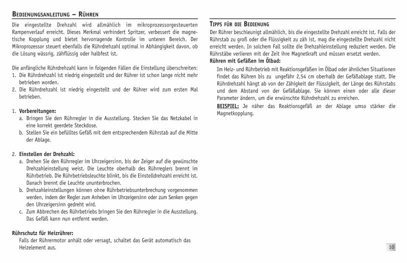
Die eingestellte Drehzahl wird allmählich im mikroprozessorgesteuertenRampenverlauf erreicht. Dieses Merkmal verhindert Spritzer, verbessert die magne-tische Kopplung und bietet hervorragende Kontrolle im unteren Bereich. DerMikroprozessor steuert ebenfalls die Rührdrehzahl optimal in Abhängigkeit davon, obdie Lösung wässrig, zähflüssig oder halbfest ist.
Die anfängliche Rührdrehzahl kann in folgenden Fällen die Einstellung überschreiten:1. Die Rührdrehzahl ist niedrig eingestellt und der Rührer ist schon lange nicht mehr
betrieben worden.2. Die Rührdrehzahl ist niedrig eingestellt und der Rührer wird zum ersten Mal
betrieben.
1. Vorbereitungen:a. Bringen Sie den Rührregler in die Ausstellung. Stecken Sie das Netzkabel in
eine korrekt geerdete Steckdose.b. Stellen Sie ein befülltes Gefäß mit dem entsprechendem Rührstab auf die Mitte
der Ablage.
2. Einstellen der Drehzahl:a. Drehen Sie den Rührregler im Uhrzeigersinn, bis der Zeiger auf die gewünschte
Drehzahleinstellung weist. Die Leuchte oberhalb des Rührreglers brennt imRührbetrieb. Die Rührbetriebsleuchte blinkt, bis die Einstelldrehzahl erreicht ist.Danach brennt die Leuchte ununterbrochen.
b. Drehzahleinstellungen können ohne Rührbetriebsunterbrechung vorgenommenwerden, indem der Regler zum Anheben im Uhrzeigersinn oder zum Senken gegenden Uhrzeigersinn gedreht wird.
c. Zum Abbrechen des Rührbetriebs bringen Sie den Rührregler in die Ausstellung.Das Gefäß kann nun entfernt werden.
Rührschutz für Heizrührer:Falls der Rührermotor anhält oder versagt, schaltet das Gerät automatisch dasHeizelement aus.
TIPPS FÜR DIE BEDIENUNGDer Rührer beschleunigt allmählich, bis die eingestellte Drehzahl erreicht ist. Falls derRührstab zu groß oder die Flüssigkeit zu zäh ist, mag die eingestellte Drehzahl nichterreicht werden. In solchem Fall sollte die Drehzahleinstellung reduziert werden. DieRührstäbe verlieren mit der Zeit ihre Magnetkraft und müssen ersetzt werden.Rühren mit Gefäßen im Ölbad:
Im Heiz- und Rührbetrieb mit Reaktionsgefäßen im Ölbad oder ähnlichen Situationenfindet das Rühren bis zu ungefähr 2,54 cm oberhalb der Gefäßablage statt. DieRührdrehzahl hängt ab von der Zähigkeit der Flüssigkeit, der Länge des Rührstabsund dem Abstand von der Gefäßablage. Sie können einen oder alle dieserParameter ändern, um die erwünschte Rührdrehzahl zu erreichen.BEISPIEL: Je näher das Reaktionsgefäß an der Ablage umso stärker dieMagnetkopplung.
BEDIENUNGSANLEITUNG – RÜHREN
10
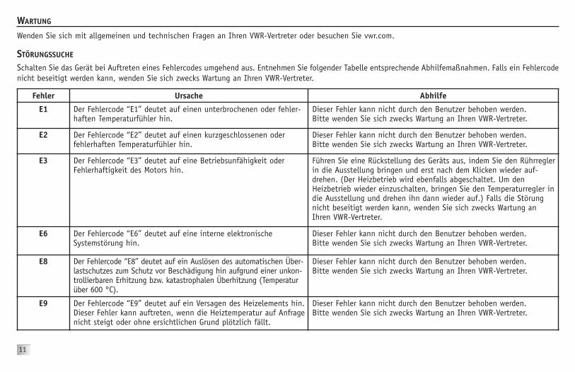
Schalten Sie das Gerät bei Auftreten eines Fehlercodes umgehend aus. Entnehmen Sie folgender Tabelle entsprechende Abhilfemaßnahmen. Falls ein Fehlercodenicht beseitigt werden kann, wenden Sie sich zwecks Wartung an Ihren VWR-Vertreter.
STÖRUNGSSUCHE
11
Fehler Ursache Abhilfe
E1 Der Fehlercode “E1” deutet auf einen unterbrochenen oder fehler-haften Temperaturfühler hin.
Dieser Fehler kann nicht durch den Benutzer behoben werden.Bitte wenden Sie sich zwecks Wartung an Ihren VWR-Vertreter.
E2 Der Fehlercode “E2” deutet auf einen kurzgeschlossenen oderfehlerhaften Temperaturfühler hin.
Dieser Fehler kann nicht durch den Benutzer behoben werden.Bitte wenden Sie sich zwecks Wartung an Ihren VWR-Vertreter.
E3 Der Fehlercode “E3” deutet auf eine Betriebsunfähigkeit oderFehlerhaftigkeit des Motors hin.
Führen Sie eine Rückstellung des Geräts aus, indem Sie den Rührreglerin die Ausstellung bringen und erst nach dem Klicken wieder auf-drehen. (Der Heizbetrieb wird ebenfalls abgeschaltet. Um denHeizbetrieb wieder einzuschalten, bringen Sie den Temperaturregler indie Ausstellung und drehen ihn dann wieder auf.) Falls die Störungnicht beseitigt werden kann, wenden Sie sich zwecks Wartung anIhren VWR-Vertreter.
E6 Der Fehlercode “E6” deutet auf eine interne elektronischeSystemstörung hin.
Dieser Fehler kann nicht durch den Benutzer behoben werden.Bitte wenden Sie sich zwecks Wartung an Ihren VWR-Vertreter.
E8 Der Fehlercode “E8” deutet auf ein Auslösen des automatischen Über-lastschutzes zum Schutz vor Beschädigung hin aufgrund einer unkon-trollierbaren Erhitzung bzw. katastrophalen Überhitzung (Temperaturüber 600 °C).
Dieser Fehler kann nicht durch den Benutzer behoben werden.Bitte wenden Sie sich zwecks Wartung an Ihren VWR-Vertreter.
E9 Der Fehlercode “E9” deutet auf ein Versagen des Heizelements hin.Dieser Fehler kann auftreten, wenn die Heiztemperatur auf Anfragenicht steigt oder ohne ersichtlichen Grund plötzlich fällt.
Dieser Fehler kann nicht durch den Benutzer behoben werden.Bitte wenden Sie sich zwecks Wartung an Ihren VWR-Vertreter.
WARTUNG
Wenden Sie sich mit allgemeinen und technischen Fragen an Ihren VWR-Vertreter oder besuchen Sie vwr.com.

BESCHREIBUNG TEILENUMMER1. Gefäßablage: Keramik-Heizplatte/Heizrührer 886311-00
Keramik-Rührer 886312-00Aluminium-Heizplatte/Heizrührer 886314-00
Aluminium-Rührer 886315-002. Frontplattenüberzug: Rührer 386257-00
Heizplatte 386260-00Heizrührer 386261-00
3. Drehknopf 286116-004. Temperaturabruf (nur Heizgeräte): Schalter 386100-00
Knopf 386101-005. Ständer-Daumenschraube 186208-006. Gehäuse 286613-007. Hitzeschutz 286607-008. Magnet: Rührer/Heizrührer 286616-009. IEC-Modul 386680-00
5-A-Sicherung 380238-0010. Motor: 286627-0011. Hauptleiterplatte: 386660-0012. Potenziometer/Leiterplatte 386661-0013. Display-Leiterplatte Heizplatte/Heizrührer 386663-00
Rührer 386662-0014. Bodenplatte 286610-0015. Bodenplatten-Verschlusskappe 186201-0016. Füße 186200-0017. Zahnscheibe 130015-0018. Erdleiter-Überbrückung Geräte mit Aluminiumablage 386678-00
Abnehmbares Netzkabel, 234 cm: EURO 330101-00UK 330102-00
SWISS 330103-00
ERSATZTEILE – 10 X 10
12

ERSATZTEILE – 18 X 18 BESCHREIBUNG TEILENUMMER1. Gefäßablage: Keramik-Heizplatte/Heizrührer 886317-00
Keramik-Rührer 886318-00Aluminium-Heizplatte/Heizrührer 886320-00
Aluminium-Rührer 886321-002. Frontplattenüberzug: Rührer 386262-00
Heizplatte 386265-00Heizrührer 386266-00
3. Drehknopf 286116-004. Temperaturabruf (nur Heizgeräte): Schalter 386104-00
Knopf 386101-005. Ständer-Daumenschraube 186208-006. Gehäuse 286614-007. Hitzeschutz 286608-008. Magnet: Rührer/Heizrührer 286616-009. IEC-Modul 386681-00
10-A-Sicherung 386005-0010. Motor: 286627-0011. Hauptleiterplatte: Heizplatte 386660-0012. Potenziometer/Leiterplatte 386661-0013. Display-Leiterplatte Heizplatte/Heizrührer 386663-00
Rührer 386662-0014. Bodenplatte 386611-0015. Bodenplatten-Verschlusskappe 186201-0016. Füße 186200-0017. Zahnscheibe 130015-0018. Erdleiter-Überbrückung Geräte mit Aluminiumablage 386678-00
Abnehmbares Netzkabel, 234 cm: EURO 330101-00UK 330102-00
SWISS 330103-00
13

ERSATZTEILE – 25 X 25BESCHREIBUNG TEILENUMMER1. Gefäßablage: Keramik-Heizplatte/Heizrührer 886323-00
Keramik-Rührer 886324-00Aluminium-Heizplatte/Heizrührer 886326-00
Aluminium-Rührer 886327-002. Frontplattenüberzug: Rührer 386270-00
Heizplatte 386273-00Heizrührer 386274-00
3. Drehknopf 286116-004. Temperaturabruf (nur Heizgeräte): Schalter 386100-00
Knopf 386101-005. Ständer-Daumenschraube 186208-006. Gehäuse 286615-007. Hitzeschutz 286609-008. Magnet: Rührer/Heizrührer 286616-009. IEC-Modul 386681-00
16-A-Sicherung 386033-0010. Motor: 286627-0011. Hauptleiterplatte: Heizplatte 386660-0012. Potenziometer/Leiterplatte 386661-0013. Display-Leiterplatte Heizplatte/Heizrührer 386663-00
Rührer 386662-0014. Bodenplatte 286612-0015. Bodenplatten-Verschlusskappe 186201-0016. Füße 186200-0017. Zahnscheibe 130015-0018. Erdleiter-Überbrückung Geräte mit Aluminiumablage 386678-00
Abnehmbares Netzkabel, 234 cm: EURO 330101-00UK 330102-00
SWISS 330103-00
14

MANUFACTURED IN NEW JERSEY, USAMANUFACTURED FOR: VWR International bvba
Researchpark Haasrode 2020Geldenaaksebaan464
B-3001 Leuven+ 32 16 385011 • http://be.vwr.com
586059-00 (Rev 1)