Embed Size (px)
Citation preview
Structural Analysis III
Structural Analysis III Revised Semester 2 Exam Information
Semester 2 2008/9
Dr. Colin Caprani
Dr. C. Caprani 1
Structural Analysis III
1. Exam Format
Introduction
The exam format is being altered this year from previous Semester 2 exam formats.
However, the change is superficial: the questions asked will be of the same standard,
and no new or extra knowledge is required. This change is being implemented to
better reflect the content of the Semester 2 course, and the time put into each topic. In
addition, it is hoped that the paper will be easy to sit and plan time for, given that all
questions will now have equal marking.
Layout
There will be 4 questions and you are to answer all 4.
Marking
Each question has equal weighting: Questions 1 to 4 are worth 25 marks each.
Timing
The exam is 2 hours in duration which converts to 30 minutes per question.
Format
The format is:
• Question 1 will examine Macaulay’s Method;
• Question 2 will examine Virtual Work;
• Question 3 will examine Virtual Work;
• Question 4 will examine Plastic Analysis.
Dr. C. Caprani 2
Structural Analysis III
In addition, questions may include aspects of qualitative analysis, corresponding to
Question 1(c) of pre-semesterized exams.
The standard and style of questions will be as for previous semesterized and pre-
semesterized exams.
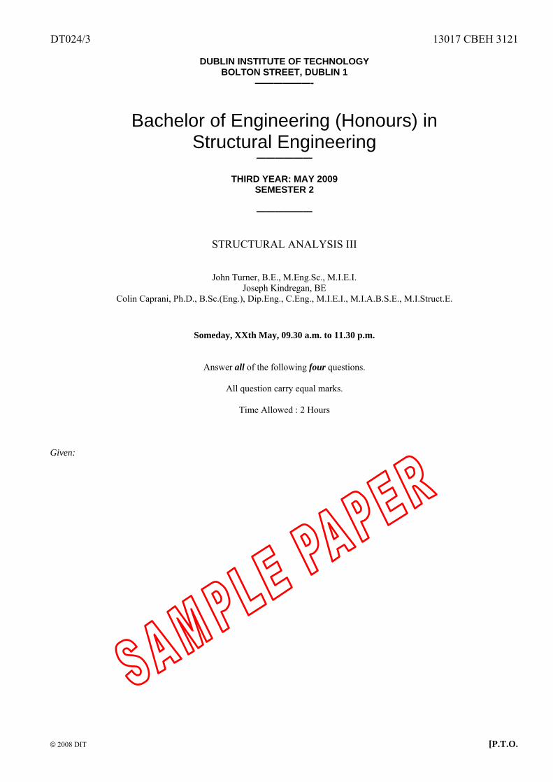
Exam Handout
The handout is as attached to the sample exam paper.
Dr. C. Caprani 3
Structural Analysis III
2. Relevant Past Exam Questions
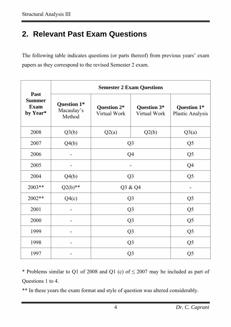
The following table indicates questions (or parts thereof) from previous years’ exam
papers as they correspond to the revised Semester 2 exam.
Semester 2 Exam Questions Past
Summer Exam
by Year* Question 1* Macaulay’s
Method
Question 2* Virtual Work
Question 3* Virtual Work
Question 1* Plastic Analysis
2008 Q3(b) Q2(a) Q2(b) Q3(a)
2007 Q4(b) Q3 Q5
2006 - Q4 Q5
2005 - - Q4
2004 Q4(b) Q3 Q5
2003** Q2(b)** Q3 & Q4 -
2002** Q4(c) Q3 Q5
2001 - Q3 Q5
2000 - Q3 Q5
1999 - Q3 Q5
1998 - Q3 Q5
1997 - Q3 Q5
* Problems similar to Q1 of 2008 and Q1 (c) of ≤ 2007 may be included as part of
Questions 1 to 4.
** In these years the exam format and style of question was altered considerably.
Dr. C. Caprani 4
DT024/3 13017 CBEH 3121
© 2008 DIT [P.T.O.
DUBLIN INSTITUTE OF TECHNOLOGY
BOLTON STREET, DUBLIN 1 ——————-
Bachelor of Engineering (Honours) in
Structural Engineering ——————
THIRD YEAR: MAY 2009
SEMESTER 2
——————
STRUCTURAL ANALYSIS III
John Turner, B.E., M.Eng.Sc., M.I.E.I. Joseph Kindregan, BE
Colin Caprani, Ph.D., B.Sc.(Eng.), Dip.Eng., C.Eng., M.I.E.I., M.I.A.B.S.E., M.I.Struct.E.
Someday, XXth May, 09.30 a.m. to 11.30 p.m.
Answer all of the following four questions.
All question carry equal marks.
Time Allowed : 2 Hours
Given:
DT024/3 13017 CBEH 3121
© 2008 DIT [P.T.O.
4
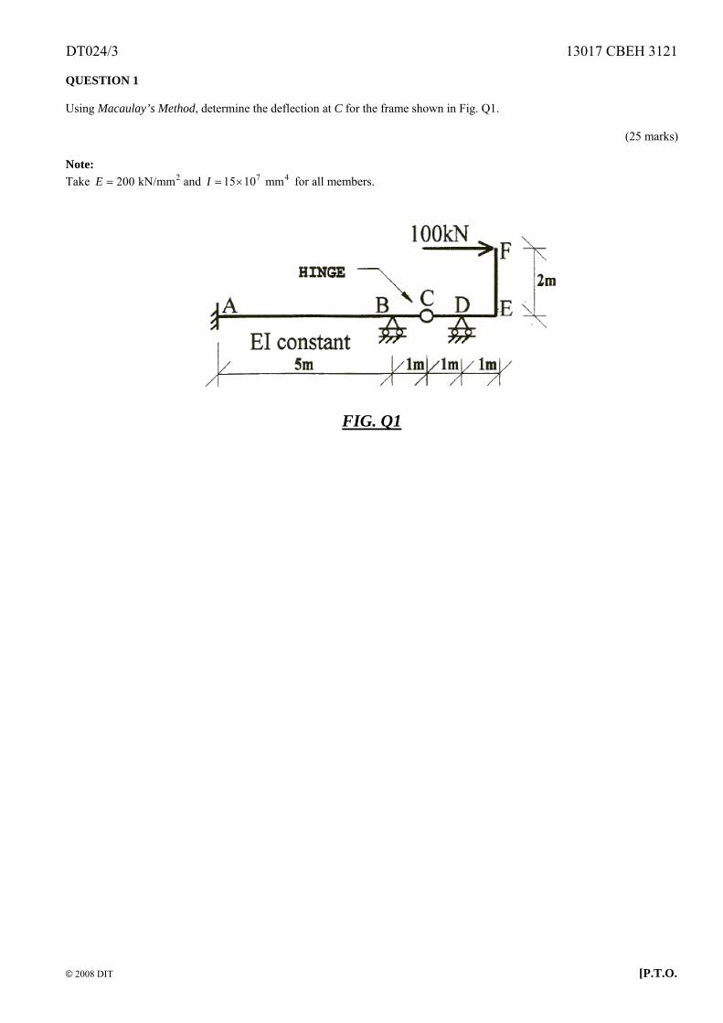
QUESTION 1 Using Macaulay’s Method, determine the deflection at C for the frame shown in Fig. Q1.
(25 marks) Note: Take and for all members. 2200 kN/mmE = 715 10 mmI = ×
FIG. Q1
DT024/3 13017 CBEH 3121
© 2008 DIT [P.T.O.
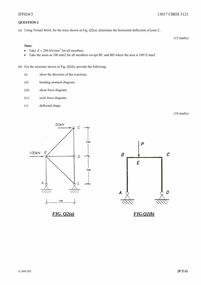
QUESTION 2 (a) Using Virtual Work, for the truss shown in Fig. Q2(a), determine the horizontal deflection of joint C.
(15 marks)
Note: • Take for all members. 2200 kN/mmE =• Take the areas as 100 mm2 for all members except BC and BD where the area is 100√2 mm2
(b) For the structure shown in Fig. Q2(b), provide the following:
(i) show the direction of the reactions; (ii) bending moment diagram; (iii) shear force diagram; (iv) axial force diagram; (v) deflected shape.
(10 marks)
FIG. Q2(a) FIG.Q2(b)
DT024/3 13017 CBEH 3121
© 2008 DIT [P.T.O.
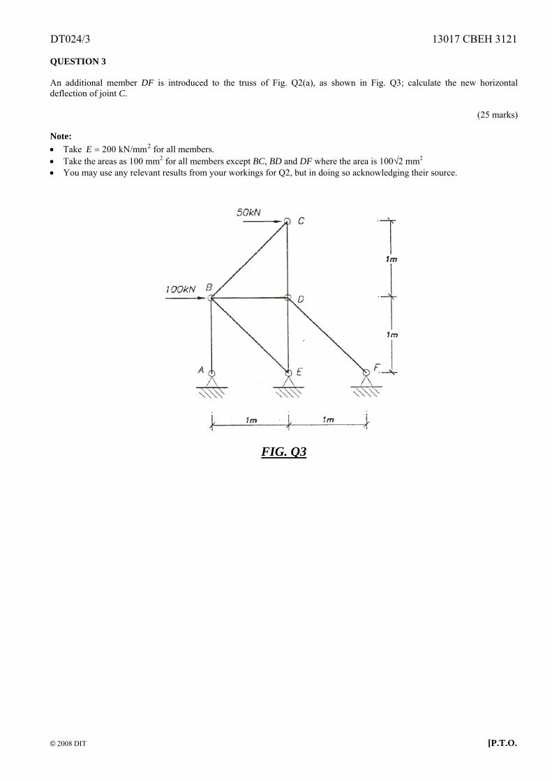
QUESTION 3 An additional member DF is introduced to the truss of Fig. Q2(a), as shown in Fig. Q3; calculate the new horizontal deflection of joint C.
(25 marks) Note: • Take for all members. 2200 kN/mmE =• Take the areas as 100 mm2 for all members except BC, BD and DF where the area is 100√2 mm2 • You may use any relevant results from your workings for Q2, but in doing so acknowledging their source.
FIG. Q3
DT024/3 13017 CBEH 3121
© 2008 DIT [P.T.O.
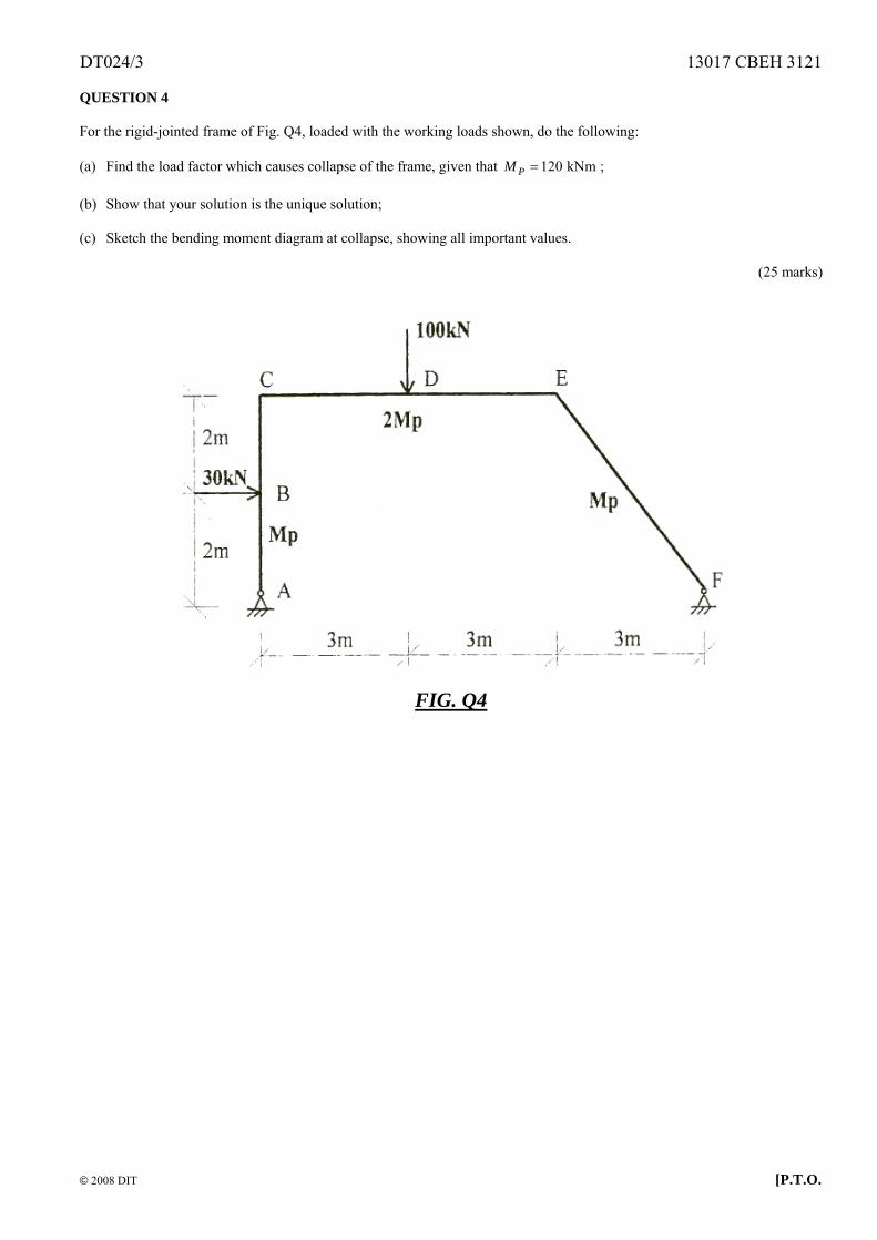
QUESTION 4 For the rigid-jointed frame of Fig. Q4, loaded with the working loads shown, do the following: (a) Find the load factor which causes collapse of the frame, given that ; 120 kNmPM = (b) Show that your solution is the unique solution; (c) Sketch the bending moment diagram at collapse, showing all important values.
(25 marks)
FIG. Q4
DT024/3 13017 CBEH 3121
© 2008 DIT [P.T.O.
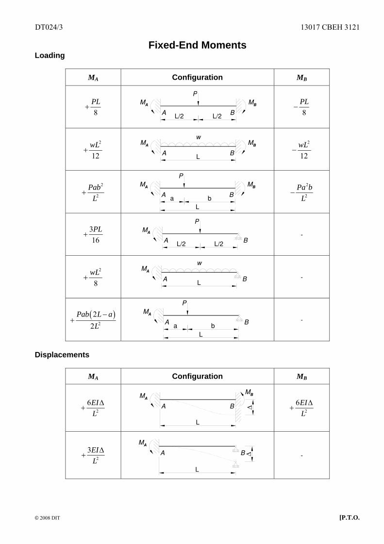
Fixed-End Moments Loading
MA Configuration MB
8PL
+
P
L/2
MA
A B
MB
L/2
8PL
−
2
12wL
+
w
L
MA
A B
MB
2
12wL
−
2
2
PabL
+
P
a
MA
A B
MB
bL
2
2
Pa bL
−
316PL
+
P
L/2
MA
A BL/2
-
2
8wL
+
w
L
MA
A B
-
( )2
22
Pab L aL−
+
P
a
MA
A bL
B
-
Displacements
MA Configuration MB
2
6EIL∆
+
MA
A B
MB
L
∆
2
6EIL∆
+
2
3EIL∆
+
L
MA
A B ∆
-
DT024/3 13017 CBEH 3121
© 2008 DIT [P.T.O.
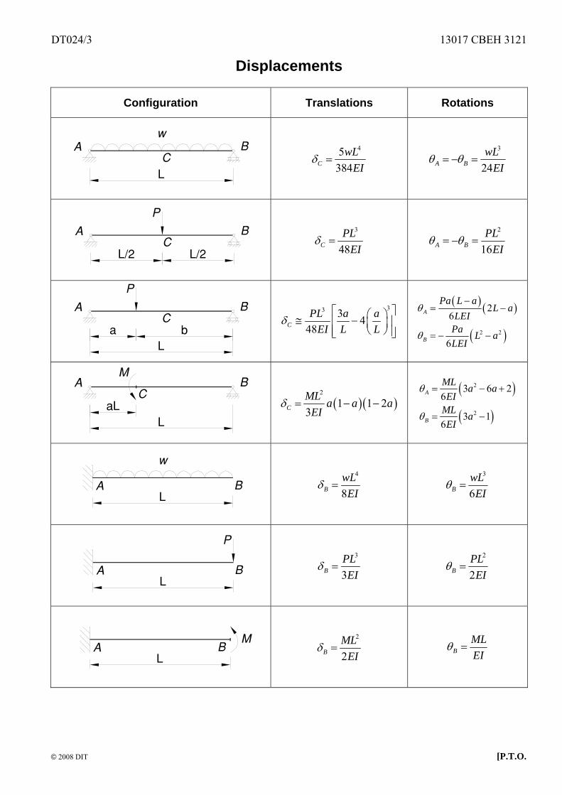
Displacements
Configuration Translations Rotations
w
L
A BC
45384C
wLEI
δ = 3
24A BwL
EIθ θ= − =
P
L/2 L/2
A BC
3
48CPL
EIδ =
2
16A BPL
EIθ θ= − =
P
a bL
A BC
33 3 448CPL a a
EI L Lδ
⎡ ⎤⎛ ⎞≅ −⎢ ⎥⎜ ⎟⎝ ⎠⎢ ⎥⎣ ⎦
( ) ( )
( )2 2
26
6
A
B
Pa L aL a
LEIPa L aLEI
θ
θ
−= −
= − −
aLL
A BC
( )(2
1 1 23CML a a a
EIδ = − − )
( )
( )
2
2
3 6 26
3 16
A
B
ML a aEI
ML aEI
θ
θ
= −
= −
+
w
LA B
4
8BwLEI
δ = 3
6BwLEI
θ =
P
LA B
3
3BPLEI
δ = 2
2BPLEI
θ =
LA B
M
2
2BML
EIδ = B
MLEI
θ =
DT024/3 13017 CBEH 3121
© 2008 DIT [P.T.O.
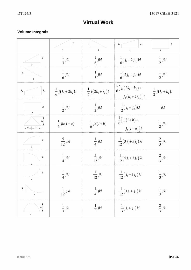
Virtual Work Volume Integrals
l
j
l
j
l
jj1 2
l
j
l
k
13
jkl 16
jkl ( )1 21 26
j j+ kl 12
jkl
l
k
16
jkl 13
jkl ( )1 21 26
j j k+ l 12
jkl
l
kk1 2
( )1 2
1 26
j k k l+ ( )1 21 26
j k k+ l ( )
( )
1 1 2
2 1 2
1 26
2
j k k
j k k l
+ +⎡⎣
+ ⎤⎦
( )1 212
j k k l+
l
k
12
jkl 12
jkl ( )1 212
j j k+ l jkl
a b
k
( )16
jk l a+ ( )16
jk l b+ ( )
( )
1
2
16
j l b
j l a k
+ +⎡⎣
+ ⎤⎦
12
jkl
l
k
512
jkl 14
jkl ( )1 21 3 5
12j j+ kl 2
3jkl
l
k
14
jkl 512
jkl ( )1 21 5 3
12j j+ kl 2
3jkl
l
k
14
jkl 112
jkl ( )1 21 3
12j j+ kl 1
3jkl
l
k
112
jkl 14
jkl ( )1 21 3
12j j k+ l 1
3jkl
k
l
13
jkl 13
jkl ( )1 213
j j k+ l 23
jkl