Embed Size (px)
Citation preview
ARTICLE IN PRESS
0927-0248/$ - se
doi:10.1016/j.so
�CorrespondE-mail addr
Solar Energy Materials & Solar Cells 92 (2008) 686–714
www.elsevier.com/locate/solmat
Review
Stability/degradation of polymer solar cells
Mikkel Jørgensen�, Kion Norrman, Frederik C. Krebs
National Laboratory for Sustainable Energy, Technical University of Denmark, Frederiksborgvej 399, DK-4000 Roskilde, Denmark
Received 13 November 2007; received in revised form 3 January 2008; accepted 4 January 2008
Available online 10 March 2008
Abstract
Polymer and organic solar cells degrade during illumination and in the dark. This is in contrast to photovoltaics based on inorganic
semiconductors such as silicon. Long operational lifetimes of solar cell devices are required in real-life application and the understanding
and alleviation of the degradation phenomena are a prerequisite for successful application of this new and promising technology. In this
review, the current understanding of stability/degradation in organic and polymer solar cell devices is presented and the methods for
studying and elucidating degradation are discussed. Methods for enhancing the stability through the choice of better active materials,
encapsulation, application of getter materials and UV-filters are also discussed.
r 2008 Elsevier B.V. All rights reserved.
Keywords: Degradation; Stability; Polymer photovoltaic; Organic solar cells; Mechanisms
Contents
1. Introduction . . . . . . . . . . . . . . . . . . . . . . . . . . . . . . . . . . . . . . . . . . . . . . . . . . . . . . . . . . . . . . . . . . . . . . . . . . . . . . . 687
1.1. Historical view of degradation in organic solar cells . . . . . . . . . . . . . . . . . . . . . . . . . . . . . . . . . . . . . . . . . . . . . . . 688
2. Chemical degradation . . . . . . . . . . . . . . . . . . . . . . . . . . . . . . . . . . . . . . . . . . . . . . . . . . . . . . . . . . . . . . . . . . . . . . . . 689
2.1. Introduction . . . . . . . . . . . . . . . . . . . . . . . . . . . . . . . . . . . . . . . . . . . . . . . . . . . . . . . . . . . . . . . . . . . . . . . . . . . 689
2.2. Diffusion of oxygen and water into the OPV device . . . . . . . . . . . . . . . . . . . . . . . . . . . . . . . . . . . . . . . . . . . . . . . 689
2.3. Photochemistry and photo-oxidation of polymers . . . . . . . . . . . . . . . . . . . . . . . . . . . . . . . . . . . . . . . . . . . . . . . . 690
2.4. Degradation as a function of polymer preparation . . . . . . . . . . . . . . . . . . . . . . . . . . . . . . . . . . . . . . . . . . . . . . . . 693
2.5. Photo-oxidation in inorganic oxide/polymer nanocomposite films . . . . . . . . . . . . . . . . . . . . . . . . . . . . . . . . . . . . . 694
2.6. Chemical degradation of the metal electrode . . . . . . . . . . . . . . . . . . . . . . . . . . . . . . . . . . . . . . . . . . . . . . . . . . . . 695
2.7. Chemical degradation of the ITO electrode . . . . . . . . . . . . . . . . . . . . . . . . . . . . . . . . . . . . . . . . . . . . . . . . . . . . . 697
2.8. Degradation of the PEDOT:PSS layer . . . . . . . . . . . . . . . . . . . . . . . . . . . . . . . . . . . . . . . . . . . . . . . . . . . . . . . . 697
2.9. Polymer materials for very stable solar cells . . . . . . . . . . . . . . . . . . . . . . . . . . . . . . . . . . . . . . . . . . . . . . . . . . . . 697
2.10. Stability and lifetime reports . . . . . . . . . . . . . . . . . . . . . . . . . . . . . . . . . . . . . . . . . . . . . . . . . . . . . . . . . . . . . . . 698
2.11. Air stable polymer solar cells . . . . . . . . . . . . . . . . . . . . . . . . . . . . . . . . . . . . . . . . . . . . . . . . . . . . . . . . . . . . . . . 698
3. Physical and mechanical degradation. . . . . . . . . . . . . . . . . . . . . . . . . . . . . . . . . . . . . . . . . . . . . . . . . . . . . . . . . . . . . . 699
3.1. Introduction . . . . . . . . . . . . . . . . . . . . . . . . . . . . . . . . . . . . . . . . . . . . . . . . . . . . . . . . . . . . . . . . . . . . . . . . . . . 699
3.2. Morphology control and morphological stability . . . . . . . . . . . . . . . . . . . . . . . . . . . . . . . . . . . . . . . . . . . . . . . . . 699
4. Characterization methods for investigation OPV of degradation . . . . . . . . . . . . . . . . . . . . . . . . . . . . . . . . . . . . . . . . . . 700
4.1. Methods based on device operation . . . . . . . . . . . . . . . . . . . . . . . . . . . . . . . . . . . . . . . . . . . . . . . . . . . . . . . . . . 700
4.1.1. Simple lifetime measurements . . . . . . . . . . . . . . . . . . . . . . . . . . . . . . . . . . . . . . . . . . . . . . . . . . . . . . . . 701
4.1.2. A standardized procedure . . . . . . . . . . . . . . . . . . . . . . . . . . . . . . . . . . . . . . . . . . . . . . . . . . . . . . . . . . . 701
4.1.3. Practical approach to reporting the operational lifetime . . . . . . . . . . . . . . . . . . . . . . . . . . . . . . . . . . . . . . 702
e front matter r 2008 Elsevier B.V. All rights reserved.
lmat.2008.01.005
ing author. Tel.: +454677 4717; fax: +45 4677 4791.
ess: [email protected] (M. Jørgensen).
ARTICLE IN PRESSM. Jørgensen et al. / Solar Energy Materials & Solar Cells 92 (2008) 686–714 687
4.1.4. IV curve measurements (diode characteristics) . . . . . . . . . . . . . . . . . . . . . . . . . . . . . . . . . . . . . . . . . . . . . 702
4.2. Methods providing information from non-specific locations in the device. . . . . . . . . . . . . . . . . . . . . . . . . . . . . . . . 702
4.2.1. Impedance spectroscopy . . . . . . . . . . . . . . . . . . . . . . . . . . . . . . . . . . . . . . . . . . . . . . . . . . . . . . . . . . . . 703
4.2.2. UV–vis spectroscopy. . . . . . . . . . . . . . . . . . . . . . . . . . . . . . . . . . . . . . . . . . . . . . . . . . . . . . . . . . . . . . . 703
4.2.3. Near-field scanning optical microscopy (NSOM) . . . . . . . . . . . . . . . . . . . . . . . . . . . . . . . . . . . . . . . . . . . 703
4.2.4. Infrared spectroscopy . . . . . . . . . . . . . . . . . . . . . . . . . . . . . . . . . . . . . . . . . . . . . . . . . . . . . . . . . . . . . . 703
4.2.5. X-ray reflectometry. . . . . . . . . . . . . . . . . . . . . . . . . . . . . . . . . . . . . . . . . . . . . . . . . . . . . . . . . . . . . . . . 703
4.3. Methods providing information from more or less specific locations in the device. . . . . . . . . . . . . . . . . . . . . . . . . . 704
4.3.1. Device accessibility . . . . . . . . . . . . . . . . . . . . . . . . . . . . . . . . . . . . . . . . . . . . . . . . . . . . . . . . . . . . . . . . 704
4.3.2. Time-of-flight-secondary ion mass spectrometry. . . . . . . . . . . . . . . . . . . . . . . . . . . . . . . . . . . . . . . . . . . . 705
4.3.3. X-ray photoelectron spectroscopy . . . . . . . . . . . . . . . . . . . . . . . . . . . . . . . . . . . . . . . . . . . . . . . . . . . . . 706
4.3.4. Atomic force microscopy. . . . . . . . . . . . . . . . . . . . . . . . . . . . . . . . . . . . . . . . . . . . . . . . . . . . . . . . . . . . 707
4.3.5. Scanning electron microscopy . . . . . . . . . . . . . . . . . . . . . . . . . . . . . . . . . . . . . . . . . . . . . . . . . . . . . . . . 707
4.3.6. Interference microscopy. . . . . . . . . . . . . . . . . . . . . . . . . . . . . . . . . . . . . . . . . . . . . . . . . . . . . . . . . . . . . 708
4.3.7. Fluorescence microscopy . . . . . . . . . . . . . . . . . . . . . . . . . . . . . . . . . . . . . . . . . . . . . . . . . . . . . . . . . . . . 708
4.3.8. Rutherford Backscattering (RBS) . . . . . . . . . . . . . . . . . . . . . . . . . . . . . . . . . . . . . . . . . . . . . . . . . . . . . . 708
4.4. Atmosphere studies (inert atmosphere, isotopically labeled oxygen and water) . . . . . . . . . . . . . . . . . . . . . . . . . . . . 708
4.5. Accelerated testing . . . . . . . . . . . . . . . . . . . . . . . . . . . . . . . . . . . . . . . . . . . . . . . . . . . . . . . . . . . . . . . . . . . . . . 709
4.6. Outdoor testing . . . . . . . . . . . . . . . . . . . . . . . . . . . . . . . . . . . . . . . . . . . . . . . . . . . . . . . . . . . . . . . . . . . . . . . . 709
5. Encapsulation techniques . . . . . . . . . . . . . . . . . . . . . . . . . . . . . . . . . . . . . . . . . . . . . . . . . . . . . . . . . . . . . . . . . . . . . . 710
5.1. Encapsulation membranes . . . . . . . . . . . . . . . . . . . . . . . . . . . . . . . . . . . . . . . . . . . . . . . . . . . . . . . . . . . . . . . . . 710
6. Conclusions . . . . . . . . . . . . . . . . . . . . . . . . . . . . . . . . . . . . . . . . . . . . . . . . . . . . . . . . . . . . . . . . . . . . . . . . . . . . . . . 711
References . . . . . . . . . . . . . . . . . . . . . . . . . . . . . . . . . . . . . . . . . . . . . . . . . . . . . . . . . . . . . . . . . . . . . . . . . . . . . . . . 711
Efficiency
ProcessStability
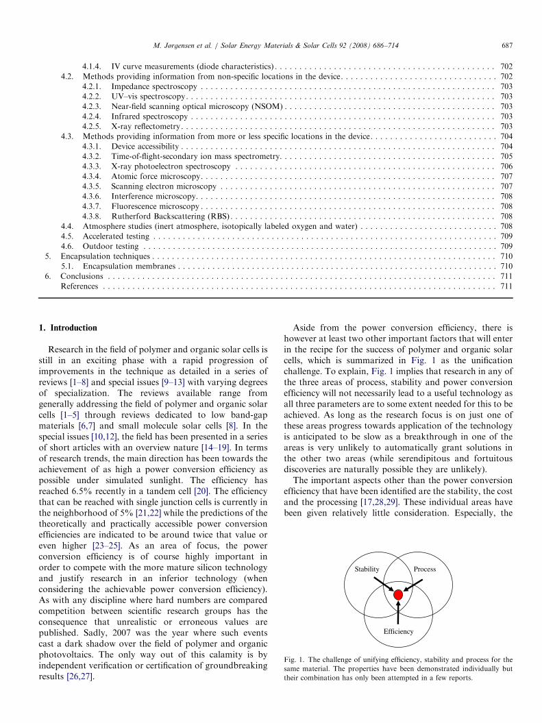
Fig. 1. The challenge of unifying efficiency, stability and process for the
same material. The properties have been demonstrated individually but
their combination has only been attempted in a few reports.
1. Introduction
Research in the field of polymer and organic solar cells isstill in an exciting phase with a rapid progression ofimprovements in the technique as detailed in a series ofreviews [1–8] and special issues [9–13] with varying degreesof specialization. The reviews available range fromgenerally addressing the field of polymer and organic solarcells [1–5] through reviews dedicated to low band-gapmaterials [6,7] and small molecule solar cells [8]. In thespecial issues [10,12], the field has been presented in a seriesof short articles with an overview nature [14–19]. In termsof research trends, the main direction has been towards theachievement of as high a power conversion efficiency aspossible under simulated sunlight. The efficiency hasreached 6.5% recently in a tandem cell [20]. The efficiencythat can be reached with single junction cells is currently inthe neighborhood of 5% [21,22] while the predictions of thetheoretically and practically accessible power conversionefficiencies are indicated to be around twice that value oreven higher [23–25]. As an area of focus, the powerconversion efficiency is of course highly important inorder to compete with the more mature silicon technologyand justify research in an inferior technology (whenconsidering the achievable power conversion efficiency).As with any discipline where hard numbers are comparedcompetition between scientific research groups has theconsequence that unrealistic or erroneous values arepublished. Sadly, 2007 was the year where such eventscast a dark shadow over the field of polymer and organicphotovoltaics. The only way out of this calamity is byindependent verification or certification of groundbreakingresults [26,27].
Aside from the power conversion efficiency, there ishowever at least two other important factors that will enterin the recipe for the success of polymer and organic solarcells, which is summarized in Fig. 1 as the unificationchallenge. To explain, Fig. 1 implies that research in any ofthe three areas of process, stability and power conversionefficiency will not necessarily lead to a useful technology asall three parameters are to some extent needed for this to beachieved. As long as the research focus is on just one ofthese areas progress towards application of the technologyis anticipated to be slow as a breakthrough in one of theareas is very unlikely to automatically grant solutions inthe other two areas (while serendipitous and fortuitousdiscoveries are naturally possible they are unlikely).The important aspects other than the power conversion
efficiency that have been identified are the stability, the costand the processing [17,28,29]. These individual areas havebeen given relatively little consideration. Especially, the
ARTICLE IN PRESSM. Jørgensen et al. / Solar Energy Materials & Solar Cells 92 (2008) 686–714688
rather poor device stability of organic solar cells has beengiven little attention. Inorganic silicon-based solar cellsmay last on the order of 25 years; so in this respect, organicdevices must be improved tremendously to becometechnologically interesting. Organic materials are by naturemore susceptible to chemical degradation from e.g. oxygenand water than inorganic materials. A number of studieshave been carried out and they show that the stability/degradation issue is rather complicated and certainly notyet fully understood though progress has been made. It isthe aim of this paper to review the relevant literature up tothis point and show how diverse the problem of devicedegradation really is. It has also been the intention to showthe variety of investigative techniques that have alreadybeen applied. If polymer solar cells are to become morethan a scientific curiosity, work in this area is highlyneeded.
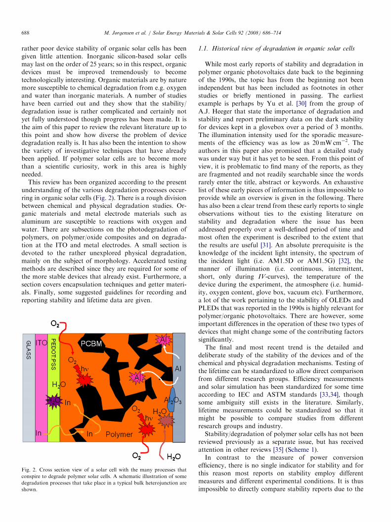
This review has been organized according to the presentunderstanding of the various degradation processes occur-ring in organic solar cells (Fig. 2). There is a rough divisionbetween chemical and physical degradation studies. Or-ganic materials and metal electrode materials such asaluminum are susceptible to reactions with oxygen andwater. There are subsections on the photodegradation ofpolymers, on polymer/oxide composites and on degrada-tion at the ITO and metal electrodes. A small section isdevoted to the rather unexplored physical degradation,mainly on the subject of morphology. Accelerated testingmethods are described since they are required for some ofthe more stable devices that already exist. Furthermore, asection covers encapsulation techniques and getter materi-als. Finally, some suggested guidelines for recording andreporting stability and lifetime data are given.
Fig. 2. Cross section view of a solar cell with the many processes that
conspire to degrade polymer solar cells. A schematic illustration of some
degradation processes that take place in a typical bulk heterojunction are
shown.
1.1. Historical view of degradation in organic solar cells
While most early reports of stability and degradation inpolymer organic photovoltaics date back to the beginningof the 1990s, the topic has from the beginning not beenindependent but has been included as footnotes in otherstudies or briefly mentioned in passing. The earliestexample is perhaps by Yu et al. [30] from the group ofA.J. Heeger that state the importance of degradation andstability and report preliminary data on the dark stabilityfor devices kept in a glovebox over a period of 3 months.The illumination intensity used for the sporadic measure-ments of the efficiency was as low as 20mWcm�2. Theauthors in this paper also promised that a detailed studywas under way but it has yet to be seen. From this point ofview, it is problematic to find many of the reports, as theyare fragmented and not readily searchable since the wordsrarely enter the title, abstract or keywords. An exhaustivelist of these early pieces of information is thus impossible toprovide while an overview is given in the following. Therehas also been a clear trend from these early reports to singleobservations without ties to the existing literature onstability and degradation where the issue has beenaddressed properly over a well-defined period of time andmost often the experiment is described to the extent thatthe results are useful [31]. An absolute prerequisite is theknowledge of the incident light intensity, the spectrum ofthe incident light (i.e. AM1.5D or AM1.5G) [32], themanner of illumination (i.e. continuous, intermittent,short, only during IV-curves), the temperature of thedevice during the experiment, the atmosphere (i.e. humid-ity, oxygen content, glove box, vacuum etc). Furthermore,a lot of the work pertaining to the stability of OLEDs andPLEDs that was reported in the 1990s is highly relevant forpolymer/organic photovoltaics. There are however, someimportant differences in the operation of these two types ofdevices that might change some of the contributing factorssignificantly.The final and most recent trend is the detailed and
deliberate study of the stability of the devices and of thechemical and physical degradation mechanisms. Testing ofthe lifetime can be standardized to allow direct comparisonfrom different research groups. Efficiency measurementsand solar simulation has been standardized for some timeaccording to IEC and ASTM standards [33,34], thoughsome ambiguity still exists in the literature. Similarly,lifetime measurements could be standardized so that itmight be possible to compare studies from differentresearch groups and industry.Stability/degradation of polymer solar cells has not been
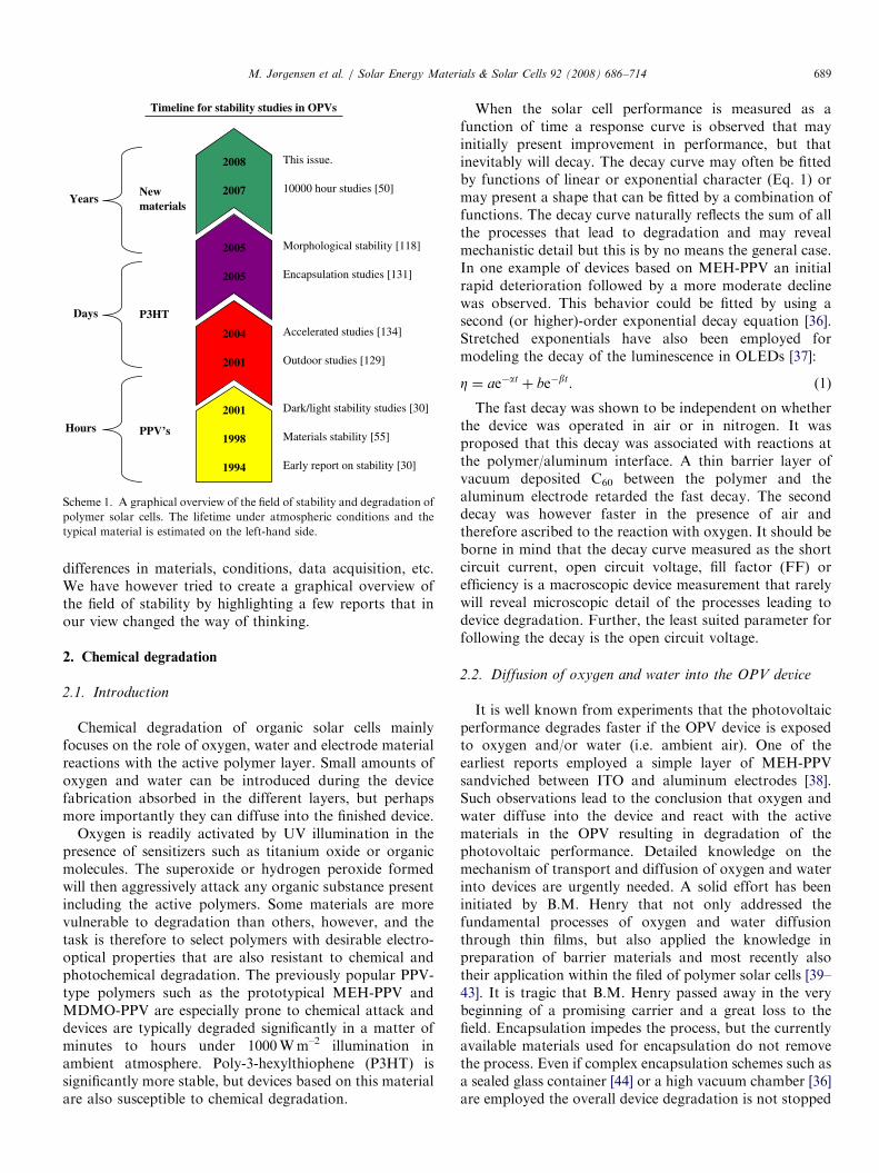
reviewed previously as a separate issue, but has receivedattention in other reviews [35] (Scheme 1).In contrast to the measure of power conversion
efficiency, there is no single indicator for stability and forthis reason most reports on stability employ differentmeasures and different experimental conditions. It is thusimpossible to directly compare stability reports due to the
ARTICLE IN PRESS
Early report on stability [30] 1994
Timeline for stability studies in OPVs
Hours
Days
Years
PPV’s
P3HT
Newmaterials
Materials stability [55] 1998
Dark/light stability studies [30] 2001
Outdoor studies [129] 2001
Accelerated studies [134] 2004
Encapsulation studies [131] 2005
Morphological stability [118] 2005
10000 hour studies [50] 2007
This issue. 2008
Scheme 1. A graphical overview of the field of stability and degradation of
polymer solar cells. The lifetime under atmospheric conditions and the
typical material is estimated on the left-hand side.
M. Jørgensen et al. / Solar Energy Materials & Solar Cells 92 (2008) 686–714 689
differences in materials, conditions, data acquisition, etc.We have however tried to create a graphical overview ofthe field of stability by highlighting a few reports that inour view changed the way of thinking.
2. Chemical degradation
2.1. Introduction
Chemical degradation of organic solar cells mainlyfocuses on the role of oxygen, water and electrode materialreactions with the active polymer layer. Small amounts ofoxygen and water can be introduced during the devicefabrication absorbed in the different layers, but perhapsmore importantly they can diffuse into the finished device.
Oxygen is readily activated by UV illumination in thepresence of sensitizers such as titanium oxide or organicmolecules. The superoxide or hydrogen peroxide formedwill then aggressively attack any organic substance presentincluding the active polymers. Some materials are morevulnerable to degradation than others, however, and thetask is therefore to select polymers with desirable electro-optical properties that are also resistant to chemical andphotochemical degradation. The previously popular PPV-type polymers such as the prototypical MEH-PPV andMDMO-PPV are especially prone to chemical attack anddevices are typically degraded significantly in a matter ofminutes to hours under 1000Wm–2 illumination inambient atmosphere. Poly-3-hexylthiophene (P3HT) issignificantly more stable, but devices based on this materialare also susceptible to chemical degradation.
When the solar cell performance is measured as afunction of time a response curve is observed that mayinitially present improvement in performance, but thatinevitably will decay. The decay curve may often be fittedby functions of linear or exponential character (Eq. 1) ormay present a shape that can be fitted by a combination offunctions. The decay curve naturally reflects the sum of allthe processes that lead to degradation and may revealmechanistic detail but this is by no means the general case.In one example of devices based on MEH-PPV an initialrapid deterioration followed by a more moderate declinewas observed. This behavior could be fitted by using asecond (or higher)-order exponential decay equation [36].Stretched exponentials have also been employed formodeling the decay of the luminescence in OLEDs [37]:
Z ¼ ae�at þ be�bt. (1)
The fast decay was shown to be independent on whetherthe device was operated in air or in nitrogen. It wasproposed that this decay was associated with reactions atthe polymer/aluminum interface. A thin barrier layer ofvacuum deposited C60 between the polymer and thealuminum electrode retarded the fast decay. The seconddecay was however faster in the presence of air andtherefore ascribed to the reaction with oxygen. It should beborne in mind that the decay curve measured as the shortcircuit current, open circuit voltage, fill factor (FF) orefficiency is a macroscopic device measurement that rarelywill reveal microscopic detail of the processes leading todevice degradation. Further, the least suited parameter forfollowing the decay is the open circuit voltage.
2.2. Diffusion of oxygen and water into the OPV device
It is well known from experiments that the photovoltaicperformance degrades faster if the OPV device is exposedto oxygen and/or water (i.e. ambient air). One of theearliest reports employed a simple layer of MEH-PPVsandviched between ITO and aluminum electrodes [38].Such observations lead to the conclusion that oxygen andwater diffuse into the device and react with the activematerials in the OPV resulting in degradation of thephotovoltaic performance. Detailed knowledge on themechanism of transport and diffusion of oxygen and waterinto devices are urgently needed. A solid effort has beeninitiated by B.M. Henry that not only addressed thefundamental processes of oxygen and water diffusionthrough thin films, but also applied the knowledge inpreparation of barrier materials and most recently alsotheir application within the filed of polymer solar cells [39–43]. It is tragic that B.M. Henry passed away in the verybeginning of a promising carrier and a great loss to thefield. Encapsulation impedes the process, but the currentlyavailable materials used for encapsulation do not removethe process. Even if complex encapsulation schemes such asa sealed glass container [44] or a high vacuum chamber [36]are employed the overall device degradation is not stopped
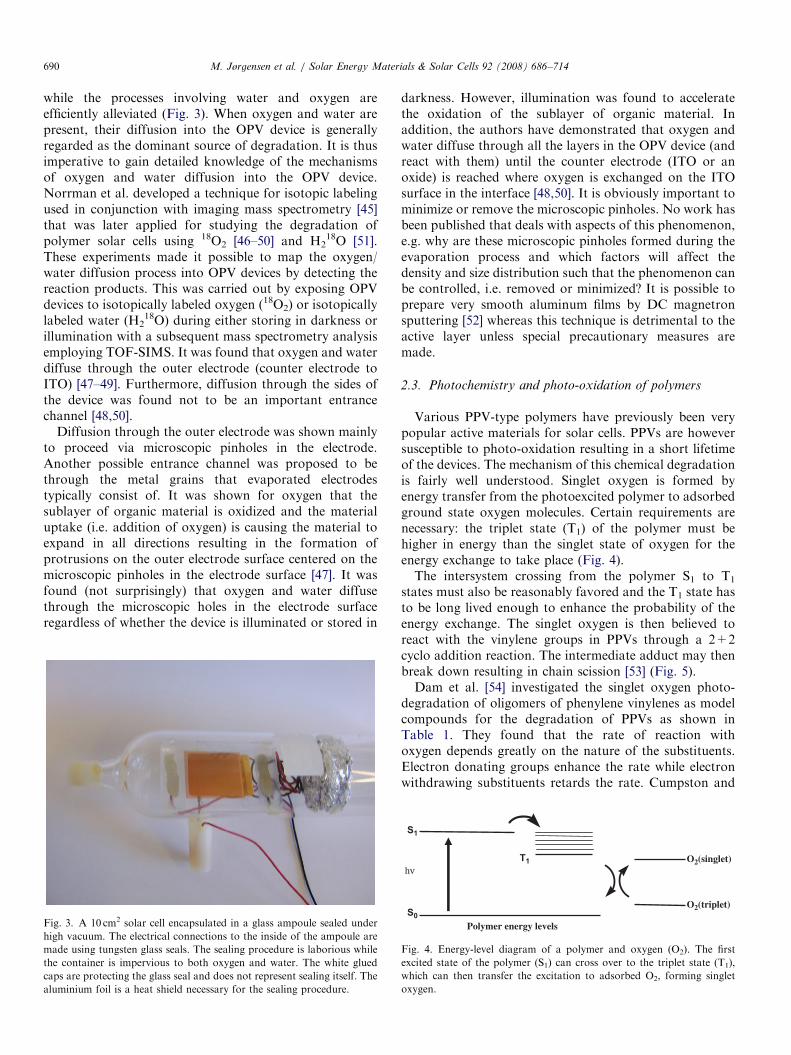
ARTICLE IN PRESSM. Jørgensen et al. / Solar Energy Materials & Solar Cells 92 (2008) 686–714690
while the processes involving water and oxygen areefficiently alleviated (Fig. 3). When oxygen and water arepresent, their diffusion into the OPV device is generallyregarded as the dominant source of degradation. It is thusimperative to gain detailed knowledge of the mechanismsof oxygen and water diffusion into the OPV device.Norrman et al. developed a technique for isotopic labelingused in conjunction with imaging mass spectrometry [45]that was later applied for studying the degradation ofpolymer solar cells using 18O2 [46–50] and H2
18O [51].These experiments made it possible to map the oxygen/water diffusion process into OPV devices by detecting thereaction products. This was carried out by exposing OPVdevices to isotopically labeled oxygen (18O2) or isotopicallylabeled water (H2
18O) during either storing in darkness orillumination with a subsequent mass spectrometry analysisemploying TOF-SIMS. It was found that oxygen and waterdiffuse through the outer electrode (counter electrode toITO) [47–49]. Furthermore, diffusion through the sides ofthe device was found not to be an important entrancechannel [48,50].
Diffusion through the outer electrode was shown mainlyto proceed via microscopic pinholes in the electrode.Another possible entrance channel was proposed to bethrough the metal grains that evaporated electrodestypically consist of. It was shown for oxygen that thesublayer of organic material is oxidized and the materialuptake (i.e. addition of oxygen) is causing the material toexpand in all directions resulting in the formation ofprotrusions on the outer electrode surface centered on themicroscopic pinholes in the electrode surface [47]. It wasfound (not surprisingly) that oxygen and water diffusethrough the microscopic holes in the electrode surfaceregardless of whether the device is illuminated or stored in
Fig. 3. A 10 cm2 solar cell encapsulated in a glass ampoule sealed under
high vacuum. The electrical connections to the inside of the ampoule are
made using tungsten glass seals. The sealing procedure is laborious while
the container is impervious to both oxygen and water. The white glued
caps are protecting the glass seal and does not represent sealing itself. The
aluminium foil is a heat shield necessary for the sealing procedure.
darkness. However, illumination was found to acceleratethe oxidation of the sublayer of organic material. Inaddition, the authors have demonstrated that oxygen andwater diffuse through all the layers in the OPV device (andreact with them) until the counter electrode (ITO or anoxide) is reached where oxygen is exchanged on the ITOsurface in the interface [48,50]. It is obviously important tominimize or remove the microscopic pinholes. No work hasbeen published that deals with aspects of this phenomenon,e.g. why are these microscopic pinholes formed during theevaporation process and which factors will affect thedensity and size distribution such that the phenomenon canbe controlled, i.e. removed or minimized? It is possible toprepare very smooth aluminum films by DC magnetronsputtering [52] whereas this technique is detrimental to theactive layer unless special precautionary measures aremade.
2.3. Photochemistry and photo-oxidation of polymers
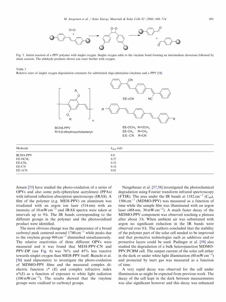
Various PPV-type polymers have previously been verypopular active materials for solar cells. PPVs are howeversusceptible to photo-oxidation resulting in a short lifetimeof the devices. The mechanism of this chemical degradationis fairly well understood. Singlet oxygen is formed byenergy transfer from the photoexcited polymer to adsorbedground state oxygen molecules. Certain requirements arenecessary: the triplet state (T1) of the polymer must behigher in energy than the singlet state of oxygen for theenergy exchange to take place (Fig. 4).The intersystem crossing from the polymer S1 to T1
states must also be reasonably favored and the T1 state hasto be long lived enough to enhance the probability of theenergy exchange. The singlet oxygen is then believed toreact with the vinylene groups in PPVs through a 2+2cyclo addition reaction. The intermediate adduct may thenbreak down resulting in chain scission [53] (Fig. 5).Dam et al. [54] investigated the singlet oxygen photo-
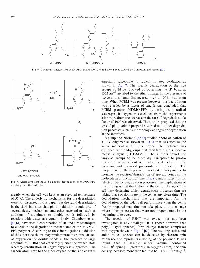
degradation of oligomers of phenylene vinylenes as modelcompounds for the degradation of PPVs as shown inTable 1. They found that the rate of reaction withoxygen depends greatly on the nature of the substituents.Electron donating groups enhance the rate while electronwithdrawing substituents retards the rate. Cumpston and
S0
S1
T1hν
O2(triplet)
O2(singlet)
Polymer energy levels
Fig. 4. Energy-level diagram of a polymer and oxygen (O2). The first
excited state of the polymer (S1) can cross over to the triplet state (T1),
which can then transfer the excitation to adsorbed O2, forming singlet
oxygen.
ARTICLE IN PRESS
O O+
OO O
O
+
Fig. 5. Initial reaction of a PPV polymer with singlet oxygen. Singlet oxygen adds to the vinylene bond forming an intermediate dioxetane followed by
chain scission. The aldehyde products shown can react further with oxygen.
Table 1
Relative rates of singlet oxygen degradation constants for substituted oligo-phenylene-vinylenes and a PPV [54]
O
O
R
R n
BCHA-PPVR=5,6-dihydroxycholestanyl-
R
R
EE-OCH3 R=OCH3EE-CH3 R=CH3E E -CN R=CN
NC
CN
EE-vCN
Molecule kdeg (rel)
BCHA-PPV 8.0
EE-OCH3 0.57
EE-CH3 0.52
EE-CN 0.16
EE-vCN 0.01
M. Jørgensen et al. / Solar Energy Materials & Solar Cells 92 (2008) 686–714 691
Jensen [55] have studied the photo-oxidation of a series ofOPVs and also some poly-(phenylene acetylenes) (PPAs)with infrared reflection absorption spectroscopy (IRAS). Afilm of the polymer (e.g. MEH-PPV) on aluminum wasirradiated with an argon ion laser (514 nm) with anintensity of 10mWcm�2 and IRAS spectra were taken atintervals up to 9 h. The IR bands corresponding to thedifferent groups in the polymer and the photooxidizedproduct were identified.
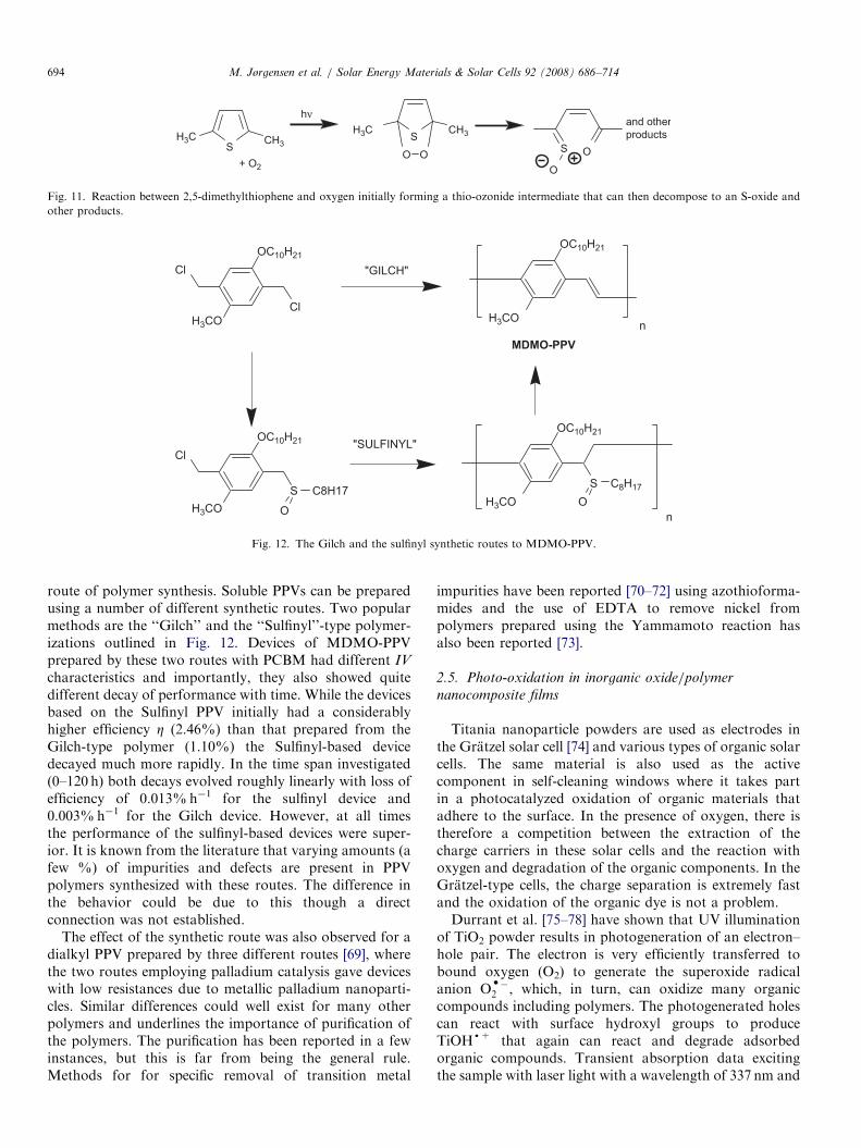
The most obvious change was the appearance of a broadcarbonyl peak centered around 1740 cm�1 while peaks dueto the vinylene group 969 cm�1 diminished simultaneously.The relative reactivities of three different OPVs weremeasured and it was found that MEH-PPV-CN andPPV-DP (see Fig. 6) was 76% and 45% less reactivetowards singlet oxygen than MEH-PPV itself. Bianchi et al.[56] used elipsometry to investigate the photo-oxidationof MDMO-PPV films and the measured complex di-electric function e* (E) and complex refractive indexn*(E) as a function of exposure to white light radiation(100mWcm�2). The results showed that the vinylenegroups were oxidized to carbonyl groups.
Neugebauer et al. [57,58] investigated the photochemicaldegradation using Fourier transform infrared spectroscopy(FTIR). The area under the IR bands at 1182 cm�1 (C60),1506 cm�1 (MDMO-PPV) was measured as a function oftime while the sample film was illuminated with an argonlaser (488 nm, 30mWcm�2). A much faster decay of theMDMO-PPV component was observed reaching a plateauafter about 3 h. When ambient air was substituted withargon no significant reduction in the IR bands wereobserved over 8 h. The authors concluded that the stabilityof the polymer part of the solar cell needed to be improvedand that protective technologies such as additives and/orprotective layers could be used. Padinger et al. [59] alsostudied the degradation of a bulk heterojunction MDMO-PPV/PCBM cell. The output current of the solar cell eitherin the dark or under white light illumination (80mWcm�2)and protected by inert gas was measured as a functionof time.A very rapid decay was observed for the cell under
illumination as might be expected from previous work. Thedecay of the cell kept in the dark between measurementswas also significant however and this decay was enhanced
ARTICLE IN PRESS
O
H3CO
R1H
H
n
O
H3CO
R1
H
n
R
-RH
O2
O
H3CO
R1O
H
n
O
OH
H3COn
hυ +
+ RCH2COOHand other products
Fig. 7. Alternative light-induced oxidative degradation of MDMO-PPV
involving the ether side chains.
O
O n
MEH-PPV
O
O NC CN n
MEH-PPV-CNn
PPV-DP
O
O
Fig. 6. Chemical structures for MEH-PPV, MEH-PPV-CN and PPV-DP as studied by Cumpston and Jensen [55].
M. Jørgensen et al. / Solar Energy Materials & Solar Cells 92 (2008) 686–714692
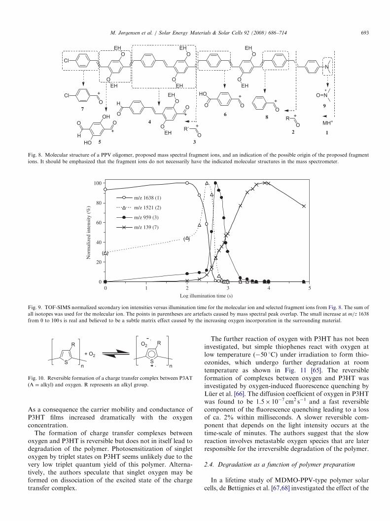
greatly when the cell was kept at an elevated temperatureof 57 1C. The underlying mechanisms for the degradationwere not discussed in this paper, but the rapid degradationin the dark indicates that photo-oxidation is only one ofseveral decay mechanisms and other mechanisms such asaddition of aluminum to double bonds followed byreaction with water are equally likely. Chambon et al.[60,61] have used a combination of IR and UV techniquesto elucidate the degradation mechanisms of the MDMO-PPV polymer. According to these investigations, oxidationof the ether side chains may predominate over direct attackof oxygen on the double bonds in the presence of largeamounts of PCBM that efficiently quench the excited statewhereby sensitization of singlet oxygen is suppressed. Thecarbon atom next to the ether oxygen of the side chain is
especially susceptible to radical initiated oxidation asshown in Fig. 7. The specific degradation of the sidegroups could be followed by observing the IR band at1352 cm�1 ascribed to the ether linkage. In the presence ofoxygen, this band disappeared over a 100 h irradiationtime. When PCBM was present however, this degradationwas retarded by a factor of ten. It was concluded thatPCBM protects MDMO-PPV by acting as a radicalscavenger. If oxygen was excluded from the experimentsa far more dramatic decrease in the rate of degradation of afactor of 1000 was observed. The authors proposed that theloss of photovoltaic properties were due to other degrada-tion processes such as morphology changes or degradationat the interfaces.Alstrup and Norman [62,63] studied photo-oxidation of
a PPV oligomer as shown in Fig. 8 that was used as theactive material in an OPV device. The molecule wasequipped with end-groups that facilitate a mass spectro-metric analysis (TOF-SIMS). The authors found thevinylene groups to be especially susceptible to photo-oxidation in agreement with what is described in theliterature and discussed previously in this section. Theunique part of the experiment was that it was possible tomonitor the reaction/degradation of specific bonds in themolecule as a function of time. Fig. 9 demonstrates this forselected specific degradation processes. The implications ofthis finding is that the history of the cell or the age of thecell may determine which degradation processes that aretaking place or dominate in the cell at any given time. Thedegradation mechanisms that are important for thedegradation of the solar cell performance when the cell isfreshly prepared may thus not take place at a later stagewhere other processes that were not preponderant in thebeginning take over.The reaction of P3HT with oxygen has not been
investigated in any detail yet. It is known however, thatpoly(3-alkylthiophenes) form charge transfer complexeswith oxygen shown in Fig. 10 [64]. The resulting cation andanion radical species can be detected by electron spinresonance and represents a doping of the polymer. It wasfound that a sample under vacuum contained5.4� 1017 spins g�1 (electrons). In oxygen (1 atm), the spindensity increased more than ten-fold to 7.1� 1018 spins g�1.
ARTICLE IN PRESS
O
OEH
EHO
OEH
EHO
OEH
EH
NCl
OCl + NO
+
O OOH
HOH
+
O
+O O
HO +
7O
OO
OEH
EHH
+
5
486
9
RO
+
2
MH+
1R´
O
+
3
Fig. 8. Molecular structure of a PPV oligomer, proposed mass spectral fragment ions, and an indication of the possible origin of the proposed fragment
ions. It should be emphasized that the fragment ions do not necessarily have the indicated molecular structures in the mass spectrometer.
0
20
40
60
80
100
0
Log illumination time (s)
Nor
mal
ized
inte
nsity
(%
)
m/z 1638 (1)
m/z 1521 (2)
m/z 959 (3)
m/z 139 (7)
( )
( )
1 2 3 4 5
Fig. 9. TOF-SIMS normalized secondary ion intensities versus illumination time for the molecular ion and selected fragment ions from Fig. 8. The sum of
all isotopes was used for the molecular ion. The points in parentheses are artefacts caused by mass spectral peak overlap. The small increase at m/z 1638
from 0 to 100 s is real and believed to be a subtle matrix effect caused by the increasing oxygen incorporation in the surrounding material.
S
R
n
+ O2S
R
.
O2
.
n
Fig. 10. Reversible formation of a charge transfer complex between P3AT
(A ¼ alkyl) and oxygen. R represents an alkyl group.
M. Jørgensen et al. / Solar Energy Materials & Solar Cells 92 (2008) 686–714 693
As a consequence the carrier mobility and conductance ofP3HT films increased dramatically with the oxygenconcentration.
The formation of charge transfer complexes betweenoxygen and P3HT is reversible but does not in itself lead todegradation of the polymer. Photosensitization of singletoxygen by triplet states on P3HT seems unlikely due to thevery low triplet quantum yield of this polymer. Alterna-tively, the authors speculate that singlet oxygen may beformed on dissociation of the excited state of the chargetransfer complex.
The further reaction of oxygen with P3HT has not beeninvestigated, but simple thiophenes react with oxygen atlow temperature (�50 1C) under irradiation to form thio-ozonides, which undergo further degradation at roomtemperature as shown in Fig. 11 [65]. The reversibleformation of complexes between oxygen and P3HT wasinvestigated by oxygen-induced fluorescence quenching byLuer et al. [66]. The diffusion coefficient of oxygen in P3HTwas found to be 1.5� 10�7 cm2 s�1 and a fast reversiblecomponent of the fluorescence quenching leading to a lossof ca. 2% within milliseconds. A slower reversible com-ponent that depends on the light intensity occurs at thetime-scale of minutes. The authors suggest that the slowreaction involves metastable oxygen species that are laterresponsible for the irreversible degradation of the polymer.
2.4. Degradation as a function of polymer preparation
In a lifetime study of MDMO-PPV-type polymer solarcells, de Bettignies et al. [67,68] investigated the effect of the
ARTICLE IN PRESS
SH3C CH3
SH3C CH3
O O+ O2
hν
S O
O
and otherproducts
Fig. 11. Reaction between 2,5-dimethylthiophene and oxygen initially forming a thio-ozonide intermediate that can then decompose to an S-oxide and
other products.
Cl
Cl
OC10H21
H3CO
"GILCH"
OC10H21
H3COn
Cl
S
OC10H21
H3COC8H17
O
S
OC10H21
H3COC8H17
On
"SULFINYL"
MDMO-PPV
Fig. 12. The Gilch and the sulfinyl synthetic routes to MDMO-PPV.
M. Jørgensen et al. / Solar Energy Materials & Solar Cells 92 (2008) 686–714694
route of polymer synthesis. Soluble PPVs can be preparedusing a number of different synthetic routes. Two popularmethods are the ‘‘Gilch’’ and the ‘‘Sulfinyl’’-type polymer-izations outlined in Fig. 12. Devices of MDMO-PPVprepared by these two routes with PCBM had different IV
characteristics and importantly, they also showed quitedifferent decay of performance with time. While the devicesbased on the Sulfinyl PPV initially had a considerablyhigher efficiency Z (2.46%) than that prepared from theGilch-type polymer (1.10%) the Sulfinyl-based devicedecayed much more rapidly. In the time span investigated(0–120 h) both decays evolved roughly linearly with loss ofefficiency of 0.013%h�1 for the sulfinyl device and0.003%h�1 for the Gilch device. However, at all timesthe performance of the sulfinyl-based devices were super-ior. It is known from the literature that varying amounts (afew %) of impurities and defects are present in PPVpolymers synthesized with these routes. The difference inthe behavior could be due to this though a directconnection was not established.
The effect of the synthetic route was also observed for adialkyl PPV prepared by three different routes [69], wherethe two routes employing palladium catalysis gave deviceswith low resistances due to metallic palladium nanoparti-cles. Similar differences could well exist for many otherpolymers and underlines the importance of purification ofthe polymers. The purification has been reported in a fewinstances, but this is far from being the general rule.Methods for for specific removal of transition metal
impurities have been reported [70–72] using azothioforma-mides and the use of EDTA to remove nickel frompolymers prepared using the Yammamoto reaction hasalso been reported [73].
2.5. Photo-oxidation in inorganic oxide/polymer
nanocomposite films
Titania nanoparticle powders are used as electrodes inthe Gratzel solar cell [74] and various types of organic solarcells. The same material is also used as the activecomponent in self-cleaning windows where it takes partin a photocatalyzed oxidation of organic materials thatadhere to the surface. In the presence of oxygen, there istherefore a competition between the extraction of thecharge carriers in these solar cells and the reaction withoxygen and degradation of the organic components. In theGratzel-type cells, the charge separation is extremely fastand the oxidation of the organic dye is not a problem.Durrant et al. [75–78] have shown that UV illumination
of TiO2 powder results in photogeneration of an electron–hole pair. The electron is very efficiently transferred tobound oxygen (O2) to generate the superoxide radicalanion Od�
2 , which, in turn, can oxidize many organiccompounds including polymers. The photogenerated holescan react with surface hydroxyl groups to produceTiOHd+ that again can react and degrade adsorbedorganic compounds. Transient absorption data excitingthe sample with laser light with a wavelength of 337 nm and
ARTICLE IN PRESS
Al
A l
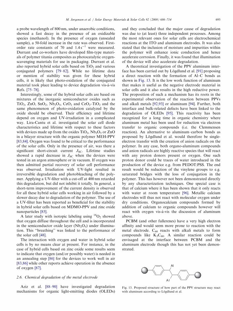
Fig. 13. Proposed structure of how part of the PPV structure may react
with aluminum according to Logdlund et al.
M. Jørgensen et al. / Solar Energy Materials & Solar Cells 92 (2008) 686–714 695
a probe wavelength of 800 nm, under anaerobic conditions,showed a fast decay in the presence of an oxidizablespecies (methanol). In the presence of oxygen (unsealedsample), a 50-fold increase in the rate was observed. First-order rate constants of 70 and 1.4 s�1 were measured.Durrant and co-workers have developed film-type materi-als of polymer titania composites as photocatalytic oxygen-scavenging materials for use in packaging. Durrant et al.also reported hybrid solar cells based on TiO2 and variousconjugated polymers [79–82]. While no lifetime dataor mention of stability was given for these hybridcells, it is likely that photo-oxidation of the conjugatedmaterial took place leading to device degradation vis-a-visRefs. [75–78].
Interestingly, some of the hybrid solar cells are based onmixtures of the inorganic semiconductor oxides such asTiO2, ZnO, SnO2, Nb2O5, CeO2 and CeO2–TiO2 and thesame phenomenon of photo-oxidation catalyzed by theoxide should be observed. Their efficiency and lifetimedepend on oxygen and UV-irradiation in a complicatedway. Lira-Cantu et al. investigated the solar cell diodecharacteristics and lifetime with respect to these factorswith devices made up from the oxides TiO2, Nb2O5 or ZnOin a bilayer structure with the organic polymer MEH-PPV[83,84]. Oxygen was found to be critical to the performanceof the solar cells. Only in the presence of air, was there asignificant short-circuit current JSC. Lifetime studiesshowed a rapid decrease in JSC when the devices weretested in an argon atmosphere or in vacuum. If oxygen wasthen admitted partial recovery of solar cell performancewas observed. Irradiation with UV-light resulted inirreversible degradation and photobleaching of the poly-mer. Applying a UV-filter with a cut-off at 400 nm retardedthis degradation, but did not inhibit it totally. In general, ashort-term improvement of the current density is observedfor all these hybrid solar cells working in air followed by aslower decay due to degradation of the polymer. The use ofa UV-filter has been reported as beneficial for the stabilityin hybrid solar cells based on MDMO-PPV and zinc oxidenanoparticles [85].
A later study with isotopic labeling using 18O2 showedthat oxygen diffuse throughout the cell and is incorporatedin the semiconductor oxide layer (Nb2O5) under illumina-tion. This ‘‘breathing’’ was linked to the performance ofthe solar cell [48].
The interaction with oxygen and water in hybrid solarcells is by no means clear at present. For instance, in thecase of hybrid cells based on zinc oxide some results seemto indicate that oxygen (and/or possibly water) is needed inan annealing step [86] for the devices to work well in air[83,86] while other reports achieve operation in the absenceof oxygen [87].
2.6. Chemical degradation of the metal electrode
Aziz et al. [88–90] have investigated degradationmechanisms for organic light-emitting diodes (OLEDs)
and they concluded that the major cause of degradationwas due to (at least) three independent processes. Amongthe most relevant ones for solar cells are electrochemicalreactions at the ITO and aluminum electrodes. It was alsostated that the inclusion of moisture and impurities withinthe polymer will enhance ionic conduction and henceaccelerate corrosion. Finally, it was found that illuminationof the device will also accelerate degradation.A theoretical investigation of the PPV aluminum inter-
face has been carried out by Logdlund et al. [91] proposinga direct reaction with the formation of Al–C bonds asshown in Fig. 13. It is the low work function of aluminumthat makes it useful as the negative electrode material insolar cells and it also results in the high reductive power.The proposition of such a mechanism has its roots in theexperimental observation of the reaction between PPVsand alkali metals [92,93] or aluminum [94]. Further, bothinterface and bulk-related defects have been linked to thedegradation of OLEDs [95]. This reactivity has beenrecognized for a long time in organic chemistry wherealuminum metal has been used for reduction via electrontransfer to organic compounds (i.e. the Clemmensenreaction). An alternative to aluminum–carbon bonds asproposed by Logdlund et al. would therefore be single-electron transfer with the creation of anion radicals on thepolymer. In any case, both organo-aluminum compoundsand anion radicals are highly reactive species that will reactwith any proton donors present or oxygen. One suchproton donor could be traces of water introduced in theproduction of the device e.g. from PEDOT:PSS. The endresult would be reduction of the vinylene groups to e.g.saturated bridges with the loss of conjugation in thepolymer. This has however not been demonstrated directlyby any characterization techniques. One special case isthat of calcium where it has been shown that it only reactswith water at room temperature [96]. Metallic calciumelectrodes will thus not react with molecular oxygen underdry conditions. Organocalcium compounds formed byaddition of calcium to organic compounds however willreact with oxygen vis-a-vis the discussion of aluminumabove.PCBM (and other fullerenes) have a very high electron
affinity and would seem more prone to reaction with themetal electrode. C60 reacts with alkali metals to formcompounds like K3C60. A similar reaction could beenvisaged at the interface between PCBM and thealuminum electrode though this has not yet been demon-strated.
ARTICLE IN PRESS
Voltage (V)
-1.0
Dev
ice
curr
ent (
mA
)
-2
-1
0
1
2800 h
3300 h
5200 h
12200 h
13000 h
-0.5 0.0 0.5 1.0
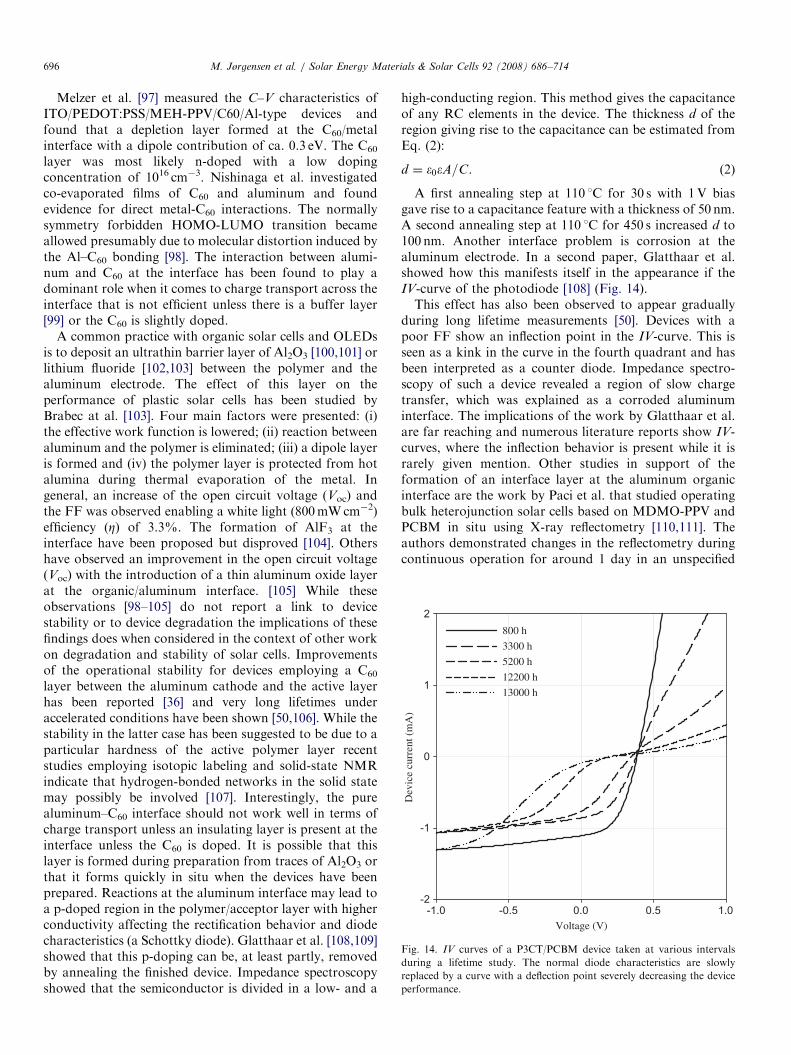
Fig. 14. IV curves of a P3CT/PCBM device taken at various intervals
during a lifetime study. The normal diode characteristics are slowly
replaced by a curve with a deflection point severely decreasing the device
performance.
M. Jørgensen et al. / Solar Energy Materials & Solar Cells 92 (2008) 686–714696
Melzer et al. [97] measured the C–V characteristics ofITO/PEDOT:PSS/MEH-PPV/C60/Al-type devices andfound that a depletion layer formed at the C60/metalinterface with a dipole contribution of ca. 0.3 eV. The C60
layer was most likely n-doped with a low dopingconcentration of 1016 cm�3. Nishinaga et al. investigatedco-evaporated films of C60 and aluminum and foundevidence for direct metal-C60 interactions. The normallysymmetry forbidden HOMO-LUMO transition becameallowed presumably due to molecular distortion induced bythe Al–C60 bonding [98]. The interaction between alumi-num and C60 at the interface has been found to play adominant role when it comes to charge transport across theinterface that is not efficient unless there is a buffer layer[99] or the C60 is slightly doped.
A common practice with organic solar cells and OLEDsis to deposit an ultrathin barrier layer of Al2O3 [100,101] orlithium fluoride [102,103] between the polymer and thealuminum electrode. The effect of this layer on theperformance of plastic solar cells has been studied byBrabec at al. [103]. Four main factors were presented: (i)the effective work function is lowered; (ii) reaction betweenaluminum and the polymer is eliminated; (iii) a dipole layeris formed and (iv) the polymer layer is protected from hotalumina during thermal evaporation of the metal. Ingeneral, an increase of the open circuit voltage (Voc) andthe FF was observed enabling a white light (800mWcm�2)efficiency (Z) of 3.3%. The formation of AlF3 at theinterface have been proposed but disproved [104]. Othershave observed an improvement in the open circuit voltage(Voc) with the introduction of a thin aluminum oxide layerat the organic/aluminum interface. [105] While theseobservations [98–105] do not report a link to devicestability or to device degradation the implications of thesefindings does when considered in the context of other workon degradation and stability of solar cells. Improvementsof the operational stability for devices employing a C60
layer between the aluminum cathode and the active layerhas been reported [36] and very long lifetimes underaccelerated conditions have been shown [50,106]. While thestability in the latter case has been suggested to be due to aparticular hardness of the active polymer layer recentstudies employing isotopic labeling and solid-state NMRindicate that hydrogen-bonded networks in the solid statemay possibly be involved [107]. Interestingly, the purealuminum–C60 interface should not work well in terms ofcharge transport unless an insulating layer is present at theinterface unless the C60 is doped. It is possible that thislayer is formed during preparation from traces of Al2O3 orthat it forms quickly in situ when the devices have beenprepared. Reactions at the aluminum interface may lead toa p-doped region in the polymer/acceptor layer with higherconductivity affecting the rectification behavior and diodecharacteristics (a Schottky diode). Glatthaar et al. [108,109]showed that this p-doping can be, at least partly, removedby annealing the finished device. Impedance spectroscopyshowed that the semiconductor is divided in a low- and a
high-conducting region. This method gives the capacitanceof any RC elements in the device. The thickness d of theregion giving rise to the capacitance can be estimated fromEq. (2):
d ¼ �0�A=C. (2)
A first annealing step at 110 1C for 30 s with 1V biasgave rise to a capacitance feature with a thickness of 50 nm.A second annealing step at 110 1C for 450 s increased d to100 nm. Another interface problem is corrosion at thealuminum electrode. In a second paper, Glatthaar et al.showed how this manifests itself in the appearance if theIV-curve of the photodiode [108] (Fig. 14).This effect has also been observed to appear gradually
during long lifetime measurements [50]. Devices with apoor FF show an inflection point in the IV-curve. This isseen as a kink in the curve in the fourth quadrant and hasbeen interpreted as a counter diode. Impedance spectro-scopy of such a device revealed a region of slow chargetransfer, which was explained as a corroded aluminuminterface. The implications of the work by Glatthaar et al.are far reaching and numerous literature reports show IV-curves, where the inflection behavior is present while it israrely given mention. Other studies in support of theformation of an interface layer at the aluminum organicinterface are the work by Paci et al. that studied operatingbulk heterojunction solar cells based on MDMO-PPV andPCBM in situ using X-ray reflectometry [110,111]. Theauthors demonstrated changes in the reflectometry duringcontinuous operation for around 1 day in an unspecified
ARTICLE IN PRESSM. Jørgensen et al. / Solar Energy Materials & Solar Cells 92 (2008) 686–714 697
inert atmosphere. These changes were linked to a growth ofthe layered structure and explained through formation ofan interface layer between the aluminum electrode and theorganic layer. The application of an interfacial layer of LiFinhibited this effect. Recent results employing synchrotronwork on heterojunction devices based on both MEH-PPVand P3HT mixed with PCBM confirm that changes do takeplace, but raise concerns as to whether X-ray reflectometryis suitable for characterization of the typically roughinterfaces of bulk heterojunction devices [112]. Thereactions at the aluminum–organic interface have beenconfirmed unequivocally in many studies employingisotopically labeled oxygen and water [36,46,47,49–51].From this point of view, the use of solar cell geometrieswith a low work function metallic cathode is likely to havesignificant degradation mechanisms and instability linkedto the reactive metal and the interface with the organic.While many of these tribulations may be circumvented byremoval of water, oxygen and by the application of suitableinterfacial barrier layers we identify the use of metallic lowwork function cathodes as problematic when it comes tomanufacturing polymer/organic solar cells with longoperational lifetimes unless the operation takes place withan efficiently encapsulated device or vacuum conditions areemployed.
2.7. Chemical degradation of the ITO electrode
The stability of the interface between indium–tin oxideand PEDOT:PSS have been studied by de Jong et al. withthe Rutherford backscattering (RBS) technique [113],which provides information on the atomic composition.Samples on glass slides with ITO/PEDOT:PSS/PPV werestored in a nitrogen atmosphere at 100 1C for up to 2500 hin the dark. RBS measurements of the PEDOT:PSS layershowed the indium content increased from 0.02% to about0.22%. When samples were exposed to ambient air a muchfaster erosion of the ITO film occurred. A film stored at8 1C in air had 1.2% indium in the PEDOT layer after 10days. It was concluded that the ITO/PEDOT interface isvery sensitive to air and that the hygroscopic nature of PSSallow absorption of water that facilitate etching of the ITOlayer. Krebs and Norrman [50] observed ITO etchingindirectly by observing indium diffusion into the layers inan OPV device with the composition Al/C60/P3CT/ITO,where P3CT is poly(3-carboxythiophene-co-thiophene).The surprising observation was the fact that indiumdiffuses through all layers in the device and ends up onthe outer surface of the counter electrode (aluminum). It isuncertain to what extent indium is involved in degradationprocesses when it diffuses through the organic layers of thedevice.
2.8. Degradation of the PEDOT:PSS layer
PEDOT:PSS or poly(ethylenedioxythiophene) poly(styr-ene sulfonic acid) is used as a hole transporting layer
between the ITO electrode and active layer. It is usuallypurchased as a somewhat ill-defined solution in water andspin-coated onto the substrate followed by drying. Kawanoet al. studied the effect of the PEDOT:PSS layer ondegradation of MDMO-PPV:PCBM solar cells and founda large difference when cells were exposed to humid versusdry conditions [114,115]. Rapid degradation were evidentin the cells illuminated under humid conditions (440%RH) either in air or in nitrogen. Cells prepared without thePEDOT:PSS layer degraded relatively slower. The authors’conclusion was that the hygroscopic PEDOT:PSS layertakes up water from the atmosphere increasing sheetresistance. Only relative values for the efficiency of most ofthe cells tested were reported, however, so direct compar-isons may be difficult. The time span used in theseexperiments was also limited to 8 h with cells degradingto 50% of the initial efficiency over 1–2 h.Norrman et al. [47] made an observation that had
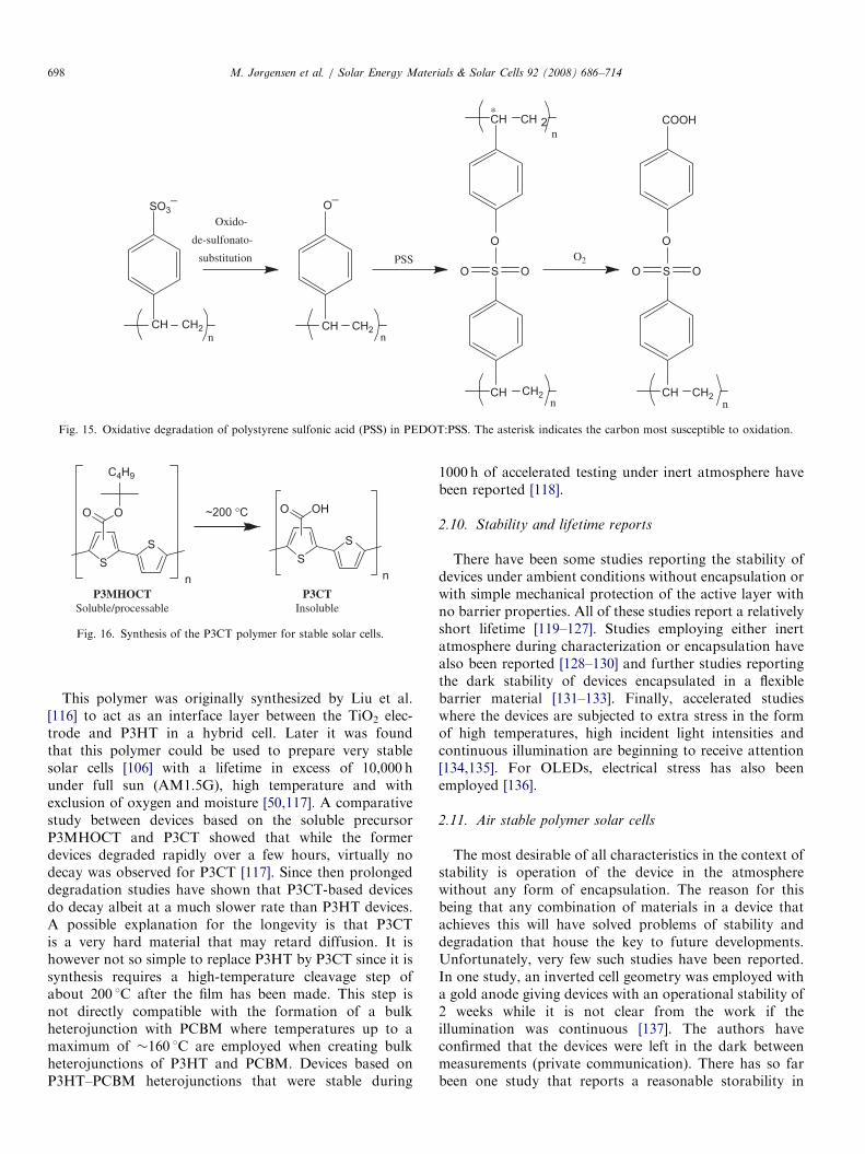
not been described before in the literature regardingthe PEDOT:PSS layer. The authors observed particleformation in an OPV device with the configurationAl/C60/C12-PPV/PEDOT:PSS/ITO. The particles are visi-ble from fluorescence microscopy images of the active areaafter the aluminum electrode had been removed. Theparticles were also observed to form over time on a partialdevice composed of C12-PPV/PEDOT:PSS/ITO. Based ona mass spectrometric analysis of these particles a molecularstructure was proposed that enabled a mechanism ofparticle formation to be proposed (Fig. 15).PSS is present in excess amount compared with PEDOT
and can thus diffuse to other parts of the device, i.e. toother layers and possibly react with other components ofthe device. The authors suggested that PSS undergoes a so-called oxido-de-sulfonato-substitution forming the pheno-late that can subsequently react with PSS forming two PSSchains linked together via a sulfonic ester group. Oxidationof the carbon indicated by an asterisk in Fig. 15 will thenconsequently form the proposed molecular structure of theparticles observed. Like many other observed phenomenain OPVs, it is uncertain to what extent particle formationcontributes to the overall device degradation. Furthermore,PEDOT:PSS is available from many sources and thedifferent suppliers employ unspecified additives that arepresent in varying amounts.
2.9. Polymer materials for very stable solar cells
Essentially, only a few categories of conjugated polymershave been examined so far for stability in solar cells mainlythe PPVs and P3HT. P3HT-based cells are superior byperhaps an order of magnitude or more in lifetime,presumably due to the lack of easily oxidizable vinylenegroups. Another significant improvement in stability wasfound with solar cells made from P3CT. This polymer initself is insoluble and hard. It is prepared in situ bythermocleavage from the soluble polyester derivative asshown in Fig. 16.
ARTICLE IN PRESS
CH CH2n
S
O
O O
COOH
CH CH2n
S
O
O O
CH CH2n
O¯
CH CH 2n
*
O2PSS
CH CH2n
SO3¯Oxido-
de-sulfonato-
substitution
Fig. 15. Oxidative degradation of polystyrene sulfonic acid (PSS) in PEDOT:PSS. The asterisk indicates the carbon most susceptible to oxidation.
SS
OO
C4H9
n
SS
OHO
n
~200 °C
P3MHOCTSoluble/processable
P3CTInsoluble
Fig. 16. Synthesis of the P3CT polymer for stable solar cells.
M. Jørgensen et al. / Solar Energy Materials & Solar Cells 92 (2008) 686–714698
This polymer was originally synthesized by Liu et al.[116] to act as an interface layer between the TiO2 elec-trode and P3HT in a hybrid cell. Later it was foundthat this polymer could be used to prepare very stablesolar cells [106] with a lifetime in excess of 10,000 hunder full sun (AM1.5G), high temperature and withexclusion of oxygen and moisture [50,117]. A comparativestudy between devices based on the soluble precursorP3MHOCT and P3CT showed that while the formerdevices degraded rapidly over a few hours, virtually nodecay was observed for P3CT [117]. Since then prolongeddegradation studies have shown that P3CT-based devicesdo decay albeit at a much slower rate than P3HT devices.A possible explanation for the longevity is that P3CTis a very hard material that may retard diffusion. It ishowever not so simple to replace P3HT by P3CT since it issynthesis requires a high-temperature cleavage step ofabout 200 1C after the film has been made. This step isnot directly compatible with the formation of a bulkheterojunction with PCBM where temperatures up to amaximum of �160 1C are employed when creating bulkheterojunctions of P3HT and PCBM. Devices based onP3HT–PCBM heterojunctions that were stable during
1000 h of accelerated testing under inert atmosphere havebeen reported [118].
2.10. Stability and lifetime reports
There have been some studies reporting the stability ofdevices under ambient conditions without encapsulation orwith simple mechanical protection of the active layer withno barrier properties. All of these studies report a relativelyshort lifetime [119–127]. Studies employing either inertatmosphere during characterization or encapsulation havealso been reported [128–130] and further studies reportingthe dark stability of devices encapsulated in a flexiblebarrier material [131–133]. Finally, accelerated studieswhere the devices are subjected to extra stress in the formof high temperatures, high incident light intensities andcontinuous illumination are beginning to receive attention[134,135]. For OLEDs, electrical stress has also beenemployed [136].
2.11. Air stable polymer solar cells
The most desirable of all characteristics in the context ofstability is operation of the device in the atmospherewithout any form of encapsulation. The reason for thisbeing that any combination of materials in a device thatachieves this will have solved problems of stability anddegradation that house the key to future developments.Unfortunately, very few such studies have been reported.In one study, an inverted cell geometry was employed witha gold anode giving devices with an operational stability of2 weeks while it is not clear from the work if theillumination was continuous [137]. The authors haveconfirmed that the devices were left in the dark betweenmeasurements (private communication). There has so farbeen one study that reports a reasonable storability in
ARTICLE IN PRESSM. Jørgensen et al. / Solar Energy Materials & Solar Cells 92 (2008) 686–714 699
ambient air without any form of encapsulation andcontinuous operation in air at 1000Wm�2, AM1.5G,7272 1C, 3575% relative humidity for 100 h to 80% ofthe initial performance. Testing under the same conditionsat a lower temperature of 30 1C gave much longeroperational lifetimes [138]. Common to the two studies isthat a relatively inert metal electrode is employed. In thelatter case, the preparation was demonstrated by allsolution processing in air (i.e. no vacuum steps).
3. Physical and mechanical degradation
3.1. Introduction
The physical degradation of organic solar cells has notbeen studied in any detail yet. It is clear that the deviceefficiency depend critically on the spatial organization ofthe different materials into layers with a precise thicknesstailored for optimum photon harvesting and charge-carriertransport. In the bulk heterojunction cells, a furtherrequirement is the nanophase separation of the activelayer into an interpenetrating network of donor andacceptor material. The best methods for obtaining thisstructure/morphology have been at the center of OPVresearch for a number of years. It is now clear that thisstructure is not static once it has been formed duringproduction of the device. Small organic molecules likePCBM and even polymers like P3HT may still have somefreedom to diffuse slowly or recrystallize over timeespecially at elevated temperature. The best structure fordevice performance will in all probability not be thethermodynamically most stable. These gradual changes inthe microstructure will lead to a degradation of theperformance of the OPVs. This type of physical degrada-tion is harder to study because we need methods to map theinternal three-dimensional (3D) structure and to correlatethis with device performance. Different types of micro-scopy have been used to gain insight into the sizedistribution of PCBM crystallites as a function of heattreatments (annealing).
3.2. Morphology control and morphological stability
The invention of the bulk heterojunction organic solarcell by Heeger et al. [139] increased the efficiency from theca. 1% obtainable with single junction cells to the ca. 5%record of today [21,22]. The exciton diffusion range in theorganic material is of the order of 10 nm limiting theoptimum size of the polymer domains. At the same time,the charges that are created at the interface between thedonor and acceptor must have continuous paths to theouter electrodes. This is solved in the bulk heterojunctioncell with the creation of an interpenetrating network ofelectron donor (polymer) and acceptor (PCBM) materials.It is, however, not obvious how to obtain the optimalnanophase separation in the final device since it is probablynot the thermodynamically most favorable geometry.
Rather it depends on the kinetics of segregation andcrystallization of the components. In most cases, apolymer/PCBM solution is spin-coated onto a substrateand many parameters such as the exact choice of solvent,concentration, ratio of donor and acceptor, temperatureand particulars about the spin-coating itself come intoplay. The optimum morphology may be further developedthrough the process of annealing where the mobility isincreased by heating the device for a short time to allowfurther migration and crystallization. Much of the im-provements in efficiencies of organic solar cells have comefrom this very experimental adjustment of the fabricationprocess of the devices rather than from theoretical break-throughs.The phase segregation of MDMO-PPV/PCBM mixtures
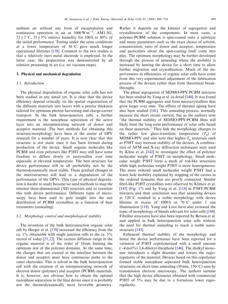
has been studied by Yang et al. in detail [140]. It was foundthat the PCBM aggregates and form microcrystallites thatgrow larger over time. The effects of thermal ageing havealso been studied [141]. This annealing process, normallyincrease the short circuit current, but as the authors note‘‘the thermal stability of MDMO-PPV:PCBM films willlikely limit the long-term performance of solar cells basedon these materials.’’ They link the morphology changes tothe rather low glass-transition temperature (Tg) ofMDMO-PPV and also note that higher-Tg materials suchas P3HT may increase stability of the devices. A combina-tion of AFM and X-ray diffraction techniques were usedby Kline et al. [142] to investigate the effect of polymermolecular weight of P3HT on morphology. Small mole-cular weight P3HT form a mesh of rod-like structureswhile high molecular weight P3HT is more homogeneous.The more ordered small molecular weight P3HT had alower hole mobility explained by trapping of the carries inthe ordered domains that are poorly connected. Similarfibril-like P3HT crystallites were observed by Klimov et al.[143] (Fig. 17) and by Yang et al. [118] in P3HT/PCBMmixtures and their conclusion was that annealing devicesat 120 1C resulted in a stable morphology with devicelifetime in excess of 1000 h at 70 1C under 1 sunillumination [118]. Yang and Loos have also reviewed thetopic of morphology of blends relevant for solar cells [144].Fibrillar structures have also been reported by Berson et al.and applied in bulk heterojunction solar cells withoutthe need for thermal annealing to reach a stable nano-structure [145].Enhanced thermal stability of the morphology and
hence the device performance have been reported for avariation of P3HT copolymerized with a small amount(�4mol%) 3,4-dihexyl-thiophene [146]. The dialkyl mono-mer introduces a slight disorder and lowers the regio-regularity of the material. Devices based on this copolymerformed stable nanophase separated bulk heterojunctionstructures on short-time annealing (30min, 150 1C) seen bytransmission electron microscopy. The authors surmisethat the high device efficiencies obtained with commercialP3HT of 5% may be due to a fortuitous lower regio-regularity.
ARTICLE IN PRESSM. Jørgensen et al. / Solar Energy Materials & Solar Cells 92 (2008) 686–714700
4. Characterization methods for investigation OPV of
degradation
In order to prevent or at least minimize the undesireddegradation of the OPV device, it is a prerequisite to beable to map the various degradation mechanisms and
Table 2
Useful and relevant techniques for studying degradation mechanisms in OPVs
Technique Bulk
analysis
Surface
analysis
2D imaging Depth
profiling
IV-curves �IPCE (EQE)
measurements
�
Impedance
spectroscopy
�
UV–vis spectroscopy �IR spectroscopy �X-ray reflectometry �RBS �TOF-SIMS � � �XPS � � �AFM � �SEM � �Interference
microscopy
� �
Efficiency 2D-imaging � �Fluorescence
microscopy
� �
Spectroscopic
ellipsometry
(�) (�)
Fig. 17. Atomic force microscopy images of low-MW P3HT (top left) and
high-MW P3HT (bottom left), (a) and (b) respectively. On the right is
shown the authors interpretation of the structure as isolated nanorods (top
right) and a more uniform high-MW film with better contact between
ordered domains. (Reproduced with permission from ACS.) [143].
understand them. This can be achieved by employing aseries of physical and chemical methods to study the OPVdegradation. Table 2 lists useful and relevant techniquesfor studying degradation mechanisms in OPVs, and, inaddition, lists relevant information associated with eachmethod.Since OPVs are multilayered devices it is important to
have techniques that can perform depth profiling to studythe degradation of each layer over time. Ideally, high-resolution in-situ 3D imaging of the chemical compositionas a function of time could resolve many of the mysteries ofthe degradation processes. Such a technique is however notavailable and while 3D imaging can be obtained it iscurrently achieved by a combination of techniques and themethodology is destructive. It is thus not possible to test adevice to a certain level, acquire a 3D image of the state ofthe device and continue testing afterwards to the next level.It is however possible to carry out a series of parallelexperiments and then sacrifice one of the experiments eachtime a sample is needed. The most powerful techniquecurrently that give a chemical 3D image is a massspectrometric technique such as TOF-SIMS that havealready been used for a number of such studies [129–131].XPS also allow for 3D imaging and gives chemicalinformation that albeit is somewhat more limited inchemical detail as compared with TOF-SIMS.
4.1. Methods based on device operation
Many of the techniques listed in Table 2 are limited togive information from the entire device. The electricalmeasurement of the device operation is such a measure-ment that only allow for the monitoring of the macroscopic
and relevant information
Destructive
analysis
Non-destructive
analysis
Chemical
information
Morphological
information
��
� (�) (�)
(�) � � (�)(�) � �(�) (�) �� (�) � (�)� � (�)� � (�)� (�) �� �� �
� (�) (�)� �
� (�) �
ARTICLE IN PRESSM. Jørgensen et al. / Solar Energy Materials & Solar Cells 92 (2008) 686–714 701
electrical transport in the device and power generationduring illumination. The most detailed source of informa-tion is the measurement of IV-curves as a function of time.From the evolution of the IV-curves information on Jsc,Voc, FF, PCE, Rsh, Rs can be extracted and the generalshape of the curve can be used to follow the degradation ofthe device performance. IPCE (or EQE) can in principlealso be employed to follow the degradation process, butthis has not been reported yet perhaps because amonitoring of Jsc essentially gives the same informationalbeit not in the same units and not specific to a particularwavelength.
4.1.1. Simple lifetime measurements
The maximum short circuit current, open circuit voltage,FF or power conversion efficiency (Jsc, Voc, FF and PCE)is measured as a function of time. Of these parameters, themost useful ones are Jsc and PCE as they relate directly todevice operation and reflect best how the device degrades.The Voc also degrade as a function of device lifetime butnot always in as straightforward a manner since it is notlinked to the machinery of the cell in the same way as theJsc and PCE that both reflect the ability of the device toconvert photons into electrons or energy. By plotting acurve of the chosen parameter as a function of time apicture of the degradation is obtained. The shape of thecurve may take many forms depending on what mechan-isms or combination of mechanisms that are preponderant.The curves may follow a linear decay, an exponential decayor a combination. Often a period of device improvement isobserved during the first part of the device life which can bedue to annealing phenomena that lead to device improve-ment at a greater rate than device degradation initially.Alas, the degradation is inevitable and always takes over atsome point.
The purpose of measuring the lifetime of a devicethrough a decay curve has several purposes. Firstly, itestablishes qualitatively whether the particular device isstable and how it degrades. Secondly and more impor-tantly, it should allow for the comparison with devicesprepared from different materials and thus ideally providea method for improving polymer solar cell stabilitythrough design of materials, devices and fabricationmethods. Even though this procedure is empirical it is inthe absence of detailed understanding and knowledge ofthe degradation mechanisms the best approach. Thirdly,when comparing the device performance in terms ofstability and degradation some suitable measure of stabilityneeds to be chosen. There is currently no consensus on howto define stability and lifetime. So far the choice has in partbeen ruled by the degradation response of the device. Forinstance devices that can be fitted by an exponentialfunction easily give access to the half-life as a parameterthat can be obtained by fitting the entire curve and thusreflect accurately some measure of the stability or durationof operation. In the case of a linear response a linear fit ispossible. There is then the problem of how to deal with
devices that exhibit an improvement during the first phaseof operation. Fourthly, some devices exhibit a constantdegradation over a large part of the lifetime curve but therate of degradation suddenly increases rapidly towards theend of the device life making projections of operationalstability difficult based on the decay profile at thebeginning of the device life. Finally, there is an issue ofperformance as one device type may be highly efficient butrelatively short lived and another one may be lessperforming but very stable in operation. A comparison oftwo such technologies may be difficult even though theymay both serve well in particular applications. Anothermeasure in such a case is thus the integral of the Jsc curveor PCE curve over the entire service life giving the totalcharge or the total energy the particular device technologycan produce during its operational lifetime. While it wouldbe desirable to have a unique measure of the performanceof a device technology in terms of stability this is difficultand could do injustice to some technologies and giveunreasonable favor to others. It is therefore proposed thata series of considerations are made when wishing tocompare lifetimes and stability performance of materialsand device technologies. It is thus not reasonable to assumethat a single fundamental parameter of degradation can beextracted and used to compare different devices. Rather, itis proposed that the stability and degradation is character-ized according to a standard that then enable theunsuspecting reader to judge when and where a particulartechnology may be applied commercially combined withother factors. For instance, a short-lived high-yieldingdevice type may be useful for one application whereas alow yielding but long-lived one may be useful in anothertype of application.
4.1.2. A standardized procedure
Presently, it may be difficult to compare results fromdifferent groups since there is no standardized lifetime test.Operational lifetimes have been measured in light, underdifferent incident light intensities, with varying spectra (i.e.AM1.5G or unspecified), under continuous or intermittentillumination, in the dark, encapsulated, in inert atmo-sphere, in air, outside under real conditions, at differenttemperatures, at specified or unspecified levels of humidity,the conditions between measurements are usually notstated, are the devices kept in the dark or under illumina-tion, under short or open circuit or under some biasvoltage. All these aspects are making quantitative compar-ison virtually impossible and are complicated further bythe fact that experimenters often have an interest inshowing their data in the best possible way. To conclude,a standardized method of reporting data would not only beuseful but is with all due likelihood an absolute require-ment for further development of the field. It is perhapspremature to fully define such a standardized method inthis review. A discussion of what such a standardizedmethod should entail however serves the purpose of thisreview well and is given in the following. Further, full
ARTICLE IN PRESSM. Jørgensen et al. / Solar Energy Materials & Solar Cells 92 (2008) 686–714702
compliance between the results obtained in differentlaboratories cannot be anticipated until complete instru-mental packages are available commercially. The para-meters that should be specified and addressed in themeasurements are most easily listed along with how to dealwith parameters that are not addressed in a givenmeasurement:
�
Light:J Source (solar simulator, halogen lamp, tungsten,laser source, real sun).J Intensity and intensity measurement (bolometric,
silicon diode).J Spectrum and filters (AM1.5G, AM1.5D, spectrum
analyzer).J Conditions (continuous, intermittent, intensity var-
iation, dark storage).
� Electrical measurement:J Source measure unit and connection to the cell.J Conditions (IV-curves, Jsc, Voc, conditions between
measurements).J Number of measurement points, step speed and
direction.J Total charge and total energy generated by the cell.
� Temperature:J Measurement (surface, substrate, surroundings).J Heating/cooling means (air circulation, solid contact
heat transfer).
� Atmosphere:J Ambient, vacuum, inert, glovebox (ppm levels of O2
and H2O).J Humidity (humidity level, humidity control).
� Device conditions:J Solid substrate, flexible substrate, encapsulation,active area.
J Electrical contacts (point contact, epoxy glue).
� Field testing:J Outdoor–indoor, day/night cycles.J Weather conditions.
This list should be considered when reporting data andwhile this is not expected that all points are addressed theirconsideration will make it easier for someone examiningthe data to evaluate the results.
4.1.3. Practical approach to reporting the operational
lifetime
The definition of operational lifetime is in traditionalengineering terms given as the period of time that elapsesbetween the initial performance and the point where 80%of the initial performance has been reached. This approachis advised when considerations of application are made butthe many different lifetime curves that may be observedshould be borne in mind and it is advised to make measure-ments of the complete lifetime curve that will enable anapplications engineer to evaluate if a given material tech-nology has a stable or flat degradation regime that can
enable application in spite of for instance a fast initialdecay. For now the best that can be done is to report asmuch detail as possible and as carefully as possible.
4.1.4. IV curve measurements (diode characteristics)
The diode characteristics are obtained by measuring thecurrent generated from the device while applying a sourcevoltage over a range of values. The current obtained at zeroapplied voltage is the short circuit current (Jsc) and thevoltage at which the current becomes zero is the opencircuit voltage (Voc). The product of these two parametersgives the theoretical maximum power of the device. Inpractice, the actual maximum power (Pmax) generated issubstantially smaller and the ratio between them gives theFF (Eq. (3)). The power conversion efficiency (Z) iscalculated using Eq. (4):
FF ¼Imax � Vmax
I sc � Voc, (3)
Z ¼ FFVoc � I sc
Pin. (4)
The diode characteristics can be modeled using theconcept of the equivalent circuit to extract more para-meters such as the series and parallel resistances of thedevice. The IV curve of an organic solar cell can howeverchange dramatically as it decays. Glatthaar et al. [108,109]have shown that an inverted region in the IV curve (leadingto a decrease in the FF) of the device could be ascribed tocorrosion at the alumina interface as described in Section2.3. This effect has also been observed to appear graduallyduring long-term measurements [50]. It is therefore usefulto measure the whole diode characteristics at regularintervals instead of just a simple parameter such as theshort circuit current. Padinger et al. [58] used thisprocedure to measure the degradation of MDMO-PPV/PCBM solar cells, in inert atmosphere, under illuminationand in the dark. The fastest decay was observed forilluminated cells heated to 67 1C. Only the ratio of currentto initial current versus time was reported however.
4.2. Methods providing information from non-specific
locations in the device
While the half-life measurements and the IV curvemeasurements provide useful information on the photo-voltaic properties other methods provide information(directly or indirectly) on either morphology or chemistry(or in some cases a combination of both). This group oftechniques can be divided into two: (i) techniques thatprovide either morphological and/or chemical informationfrom specific spatial locations in the device, and (ii)techniques that provide information from e.g. all layersand typically averaged over a large area perpendicular tothe thickness of the device. Examples of the latter are givenin the following with specific emphasis on the applicabilitywith regard to studying OPV degradation. Most of the
ARTICLE IN PRESSM. Jørgensen et al. / Solar Energy Materials & Solar Cells 92 (2008) 686–714 703
spectroscopic techniques give results averaged over thewhole device, such as the UV–vis and IR spectra thoughthey can be adapted to give crude but useful two-dimensional (2D) information.
4.2.1. Impedance spectroscopy
Impedance or dielectric spectroscopy measures thedielectric properties of a material as a function offrequency. For a polymer solar cell, the results can beinterpreted in terms of the equivalent circuit with aresistive/capacitive (RC) element. Usually, impedancespectra are plotted as the real part of the impedance versusthe imaginary part. An RC element is seen as a semicirclefrom which the capacitance can be derived. The techniquehas been used to monitor the progress of the annealingprocess [109]. During degradation an inverted region in thediode characteristics have been observed that has beenexplained using impedance spectroscopy as the formationof a dielectric layer at the active layer/alumina interfacepossibly aluminum oxide as described in Section 2.6.Meltzer et al. have investigated the C60/metal interface andconcluded that the results could be explained by theformation of a depletion layer with n-doping of the C60
layer [97]. Pradhan and Pal studied photovoltaics com-posed of organic molecules of Rose Bengal and copper(-II)phthalocyanine and correlated the real part of thepermittivity (e0) with the short circuit current [147].
4.2.2. UV–vis spectroscopy
Photo-oxidation of polymers used in organic solar cellsare also called photobleaching because the process leads toloss in conjugation destroying the chromophores responsiblefor the color. The rate of singlet oxygen degradation of aPPV polymer and some substituted oligomers were investi-gated using UV–vis spectroscopy by Dam et al. [53] (see alsoSection 2.3). A plot of the linear correlation between thenatural logarithm to the relative absorption (ln(At/A0)) andthe photolysis time gave the rate constants (kdeg).
Kroon et al. [148] used the so-called light beam-inducedcurrent measurements (LBIC) to obtain 2-D maps of thepolymer solar cell photoelectric response over time. In thistechnique, the cell is scanned with a light beam (xenonlamp source, 0.5mm diameter) while the short circuitcurrent (Isc) is measured. The devices investigated were theMDMO-PPV:PCBM type with an initial efficiency (Z) of2.55%. Initially, the LBIC images showed that the responseof the device was uniform over the active area and thendegraded substantially over the 457 h test period.
Jeranko et al. [128] have used a similar type of laser-induced photocurrent efficiency mapping of MDMO-PPV/PCBM solar cells as they degraded over time. Most cellsgave rather homogeneous images from the start thatdeteriorated especially at the edges. This effect could alsobe demonstrated clearly in a cross-sectional scan. After 2weeks of degradation, the area that was still active hadbecome very inhomogeneous and later developed intosmall islands after 2 months of dark storage. In a few
instances, some areas at the right rim of the cells were up tothree times more efficient than the rest of the solar cell.This believed to be due to special conditions duringdeposition of the aluminum layer and the conclusion wasthat the nature of the aluminum/polymer interface played akey role in the electron and hole transfer. It was suggestedthat this imaging technique might be useful in a combina-torial approach to track down variations across the device.
4.2.3. Near-field scanning optical microscopy (NSOM)
McNeill et al. used a modified NSOM technique callednear-field scanning photocurrent microscopy (NSPM) tocorrelate morphology with current generation in polymersolar cells [149]. In this instrument light from a 409 nm laserilluminate the device through a fiber optic AFM-type tipthat is scanned over the sample while the current response ismonitored. Both normal AFM images and NSPM imagescan be taken at the same time allowing the directcomparison between the morphology and current response.No conclusions on how the device morphology affects theefficiency or degradation of polymer solar cells were made.This was only a demonstration of the possibilities of thetechnique. It has an obvious interest however, since it is oneof a few methods that can characterize the solar cellperformance at the nanometer level.
4.2.4. Infrared spectroscopy
Infrared spectroscopical techniques probe the localchemistry and can be used study the time dependantevolution of intensity of signals from discrete functionalgroups in polymers. Either IRAS (IRAS spectroscopy) orFTIR to investigate the degradation of PPV polymers insolar cells has been described in Section 2.2. These studiesshow a decrease in vinylene bond signals and an increase incarbonyl group signals expected in the oxidative degrada-tion of this type of polymers [54,56,57].
4.2.5. X-ray reflectometry
Energy dispersive X-ray reflectometry has been used tostudy the time-dependant degradation of polymer solarcells based on MDMO-PPV/PCBM by Paci et al. [110,111].The technique measures the reflected intensity of X-raysand probes the thickness, roughness and electron density ofthe layer structure of thin-film devices. Paci et al. used awhite incident X-ray beam produced by a standard 2 kWtungsten anode X-ray tube and detected by a solid-stategermanium detector. Cells composed of the structure:glass/ITO/PEDOT/MDMO-PPV:PCBM/Al or glass/ITO/MDMO-PPV:PCBM/LiF/Al were studied. The resultsshowed oscillations in the reflected intensity that wereinterpreted as due to the aluminum electrode layer. The cellswere investigated both under illumination and in the darkand a significant thickening of the layer was observed. Twopossible explanations were offered. The first was that areaction occurred at the aluminum polymer interface with theformation of an aluminum oxide layer. The second explana-tion was that indium atoms from the ITO layer diffused into
ARTICLE IN PRESSM. Jørgensen et al. / Solar Energy Materials & Solar Cells 92 (2008) 686–714704
the organic layer. Independent results employing synchrotronradiation as the source of X-rays for the reflectometryexperiment have confirmed that changes take place but alsoshow that the surface roughness of the evaporated aluminum(�10nm) is so large that X-ray reflection features areprobably not observed from this layer [112].
4.3. Methods providing information from more or less
specific locations in the device
The methods described in Section 4.2 provide spatiallynon-specific information, i.e. typically averaged informa-tion from either the entire device or from localized areas onthe device surface but with the information averaged fromall the device layers. Furthermore, some of the techniquescan only be used on the individual materials prior toincorporation into the device, i.e. not directly on the OPVdevice.
From a degradation point of view, it is very useful to beable to describe the in-plane and/or in-depth distribution ofmorphology and/or chemistry. The applicability of theavailable techniques varies. Techniques such as TOF-SIMSand XPS are cable of performing surface sensitive imagingand depth profiling and are thus versatile techniques. Othertechniques are entirely imaging techniques with varyinglateral resolutions, e.g. AFM, SEM, interference micro-scopy and fluorescence microscopy. Often a suite ofimaging techniques is used to obtain complementaryinformation. Imaging techniques cannot be used directlyon the OPV device (except on the surface of the outerelectrode). Scattering techniques such as RBS and spectro-scopic ellipsometry are unique in the sense that they canprovide information from specific layers in the devicewithout gaining access by physical means. In order to
ITO
Glass substrate
AlC 60
C 12-PPV
PEDOT:PSS
ITO
Glass substrate
ITOGlass substrate
AlC60
C12-PPV
PEDOT:PSS
ITO
Glass substrate
Surface characterization
Peel
Was
Fig. 18. Schematic showing the various steps involved in getting access to
PEDOT:PSS/ITO: (A) The intact organic solar cell device. (B) The outcome of
washed off C60 and C12-PPV using chloroform. (D) The outcome of having w
employ the pure imaging techniques and benefit from thecomplementary information, it is necessary to gain accessto the various layers/interfaces of the device.
4.3.1. Device accessibility
Ideally each layer in the device should be selectivelyremoved. However, this is not always possible and there isalways the risk of modifying the exposed surfaces/interfaces. Various processes can interfere when exposingthe surfaces/interfaces, such as reaction of exposed organicmaterial with oxygen and water (if handled in ambient air).Another problematic phenomenon is surface segregation,i.e. once a layer has been removed it could induce surfacesegregation of species from at least the bulk layer material.These possible phenomena should be considered wheninterpreting the subsequent analysis data.The procedure of gaining access to the device by stepwise
removal of the layers is schematically described in Fig. 18.The shown device has the composition Al/C60/C12-PPV/PEDOT:PSS/ITO. The procedure will of course depend onthe composition. The Al electrode can be removed from theintact device by carefully applying a piece of adhesive tapeon the active area, which is then pulled off very quicklyexposing the Al/C60 interface for surface analysis. The C60
layer is removed by dipping a cotton swap in chloroform,and gently sweeping it across the exposed surface. In thiscase, the C12-PPV is also removed. Since both C60 and C12-PPV are soluble in the same solvents it is not possible toselectively remove each layer. The exposed PEDOT:PSSsurface can now undergo surface characterization. ThePEDOT:PSS layer is not soluble in chloroform but inwater, so the chloroform procedure is simply repeatedusing (ultrapure) water instead, which exposes the ITOsurface for further surface analysis.
PEDOT:PSS
ITO
Glass substrate
Surfacecharacterization
C 60C 12-PPV
PEDOT:PSS
ITO
Glass substrate
PEDOT:PSS
ITO
Glass substrate
Surface characterization
h
Was
h
C60
C12-PPV
PEDOT:PSS
ITO
Glass substrate
the various layers/interfaces of a device composed of Al/C60/C12-PPV/
peeling off the Al electrode using adhesive tape. (C) The outcome of having
ashed off the PEDOT:PSS using water. C12 corresponds to dodecyl.

ARTICLE IN PRESSM. Jørgensen et al. / Solar Energy Materials & Solar Cells 92 (2008) 686–714 705
4.3.2. Time-of-flight-secondary ion mass spectrometry
The versatile nature of TOF-SIMS has proven to bevaluable when studying degradation mechanisms in OPVs.The probe depth is only 1–2 nm and the basic outcome ismass spectral information that contains an overwhelmingamount of typically complex information. In particular fororganic materials valuable information on the molecularstructure can be obtained that enables monitoring ofstructural changes as a function of varied conditions, e.g.the effect of oxygen and/or water exposure on themolecular structure of the active material in an OPVduring illumination or during storage in darkness. TOF-SIMS being a mass spectrometry-based technique makes itobvious and advantageous to employ isotopically labeledoxygen (18O2) or water (H2
18O) in experiments dealing withoxidative degradation of OPVs and/or reaction with water.
4.3.2.1. Imaging. Besides obtaining a mass spectrum overand area of down to a few micrometers, TOF-SIMS canperform imaging as schematically illustrated in Fig. 19.
During analysis a mass spectrum is obtained fromseveral points on the surface. Each point becomes a pixelin the resulting image, i.e. each pixel represents a massspectrum. The intensity distribution of a mass spectralmarker for a given species on the surface will then, via acolor intensity bar (gray scale in Fig. 19), provide an(digital) ion intensity image of that species over theanalyzed area, i.e. visualize the in-plane distribution offor example an oxidation product in an organic interface inthe OPV. Different imaging techniques typically vary inprobe depth, area coverage, lateral resolution (imageresolution) and the type of information acquired. TOF-SIMS has, as mentioned earlier, a probe depth of 1–2 nm,area coverage from a few square micrometers to �100 cm2,a lateral resolution down to �50 nm, and provideschemical information via mass spectral data.
Fig. 20 shows the result of imaging the accessibleinterfaces in an OPV device composed of Al/C60/C12-PPV/PEDOT:PSS/ITO. The device was illuminated(1000Wm�2, AM1.5) in an 18O2/N2 atmosphere (1 atm)for 45 h and was subsequently imaged using TOF-SIMS.By monitoring the 18O�/16O� intensity ratio over theanalyzed area, it becomes possible to visualize the 18Oincorporation that occurred during illumination (if incor-poration did occur the ratio should exceed the natural ratioof 0.2%). The observed circular oriented incorporation in
m/z
Inte
nsity
9×9
0%10
0%
m/z
Fig. 19. Schematic of the process of creatin
the lateral plane led to the conclusion that this type ofincorporation is a consequence of microscopic holes in theAl electrode. 18O2 diffuses vertically through the holes andexpands in all lateral directions reacting with C60, whereafter the 18O becomes fixed in degradation products. Thefact that incorporation is observed at all analyzedinterfaces suggests that oxygen diffuses through the outerAl electrode and continues through all the other layers andends up incorporated in the ITO electrode. Until theseresults, it was not known that oxygen diffuses through theentire device to the counter electrode.
4.3.2.2. Depth profiling. If the imaging analysis is com-plemented by a sputter process depth profiling becomespossible. Whereas TOF-SIMS imaging is used to visualizein-plane distribution of chemistry TOF-SIMS depthprofiling is used to visualize in-depth distribution ofchemistry. The process is schematically shown in Fig. 21.Switching between a sputter process (digging a hole in thesurface) and imaging enables monitoring of chemistry as afunction of depth, i.e. enables depth profiling. Since depthprofiling is actually imaging as a function of depth, it is infact 3D information that is acquired. The often unknownsputter rate varies for different materials (e.g. when goingthrough the layers in an OPV device), so the actual depth isnot well defined. Complementary techniques are typicallyused to determine the film thickness.Not only oxygen is observed to diffuse through the outer
electrode to the counter electrode, water has been shown toexhibit the same behavior. Fig. 22 shows depth profiles fora device with the composition Al/MEH-PPV:PCBM/PEDOT:PSS/ITO that was exposed to saturated H2
18Oduring illumination (1000Wm�2, AM1.5). Water is,according to the depth profile, observed to be incorporatedat least into the MEH-PPV:PCBM layer. However, ananalysis equivalent to that shown in Fig. 22 confirmed thatwater also reaches the ITO and incorporates 18O (thesputter process drastically reduces the sensitivity due tocharge build-up).Fig. 23 displays a depth profile of a device with the
composition Al/C60/P3CT/ITO, and shows depth profilesfor Al+ and In+ that are mass spectral markers for the twocounter electrodes aluminum and ITO. The two markersare detected through the entire device (disregarding thesubstrate). The explanation is found in the phenomenoncalled interlayer diffusion (not to be mistaken for interlayer
pixels Ion image
g an ion image from TOF-SIMS data.
ARTICLE IN PRESS
A
Inte
nsity
BC
D
Sputter time
D
Interface species
Fig. 21. Schematic of the process of performing a TOF-SIMS depth profile through a multilayer film (A). The surface is bombarded with sputter ions (B)
that consequently removes material from the surface thus creating a hole. By switching between sputter ions (B) and analysis ions (primary ions) secondary
ions (C) can be collected/detected as a function of the sputter time. A depth profile is constructed (D) by plotting the intensity of the secondary ions
(specific ions from each layer) against the sputter time.
Al/C60
18O/16O (%) = 2.4 ±0.5 1.9 ±0.5 0.45 ±0.04
PPV/PEDOT
0% 100%Intensity
ITO
PEDOT:PSS
C12-PPV
C60
Al
PEDOT/ITO
Fig. 20. TOF-SIMS images (0.5� 0.5mm2) of three interfaces in an OPV device with the configuration Al/C60/C12-PPV/PEDOT:PSS/ITO. C12
corresponds to dodecyl. The images visualize the normalized lateral intensity distribution of the 18O/16O ratio. The 18O/16O ratio values in the lower right
corners are averages of 10 measurements each covering 0.1� 0.1mm2 from various surface locations.
M. Jørgensen et al. / Solar Energy Materials & Solar Cells 92 (2008) 686–714706
mixing). In this case, the electrode material is slowlydissolved in the other layers, i.e. electrode material isdiffusing through the entire device and thus contributing tothe overall degradation of the device.
TOF-SIMS has been used in numerous studies [45–51,62,63,84,150–153] and also in the field of OLEDs [153,154].
4.3.3. X-ray photoelectron spectroscopy
XPS is very similar to TOF-SIMS in the sense that it hasa probe depth of 5–10 nm, area coverage up to some square
centimeters, a lateral resolution down to �30 mm, andprovides chemical information via measured core electron-binding energies. Furthermore, sputtering is also used incombination with this technique so depth profiling is alsopossible. The imaging capabilities and the sensitivity areinferior to that of TOF-SIMS. The strength of XPS,however, is the fact that is a quantitative technique thatproduces much less complex data compared with TOF-SIMS, which is relatively straightforward to interpret.XPS is an elemental analysis and provides valuable
ARTICLE IN PRESS
Fig. 22. TOF-SIMS depth profiles of an organic solar cell with the
configuration Al/MEH-PPV:PCBM/PEDOT:PSS/ITO. AlO�2 is a marker
for aluminium oxide, C�4 is a marker for MEH-PPV:PCBM and
PEDOT:PSS, S� is a marker for PEDOT:PSS, and InO�2 is a marker
for ITO.
Al C P3CT ITO
1
10
100
1000
10000
100000
1000000
10000000
0
Sputter time (min.)
Inte
nsity
(co
unts
)
Al+
In+
Al C60 P3CT ITO
20 40 60 80 100 120
Fig. 23. TOF-SIMS depth profiles of an OPV device with the configura-
tion Al/C60/P3CT/ITO. P3CT corresponds to poly(3-carboxydithio-
phene).
Fig. 24. SEM image (2.3� 1.7 mm2) of the outer electrode surface of a
device with the composition Al/C60/C12-PPV/PEDOT:PSS/ITO.
M. Jørgensen et al. / Solar Energy Materials & Solar Cells 92 (2008) 686–714 707
(quantitative) information on the chemical state, which isespecially useful with respect to carbon when studyingOPV degradation. The depth profiling and imagingcapabilities have not yet been exploited for the study ofOPV degradation. Focus has been on averaged informa-tion on the chemical state. However, due to the comple-mentary information XPS is often used in combinationwith TOF-SIMS.
4.3.4. Atomic force microscopy
AFM is an imaging technique that typically maps thesurface with respect to surface topography (can, however,provide chemical contrast information if used in alternativemodes). AFM can cover only a limited analysis area, buthas an excellent lateral resolution (Angstrøm range) and anexcellent height resolution (Angstrøm range), which makesit the obvious choice for the study of OPV degradation as aresult of morphology changes on a nanoscale. However,the typical application for AFM with regard to OPVs hasbeen to monitor and thus optimize the nanostructure of
bulk heterojunction blend films in order to optimize theOPV efficiency.AFM has been used to study the microscopic holes in the
outer electrode of an OPV. It was found that eachmicroscopic hole was centered in a surface protrusion.The microscopic holes were found to be the main entrancechannels for oxygen and water and the protrusions wassuggested to be a consequence of the resulting oxidation ofthe underlying organic material due to the formation ofoxides (material build-up).
4.3.5. Scanning electron microscopy
SEM is an imaging technique and has become a standardtool for visualizing morphology in OPVs. The strength ofthe technique is the superior lateral resolution and thecapability of analyzing a broad range of scales fromnanometer range to millimeter range. The weakness is thelack of a depth scale.Just as AFM the typical application for SEM with
regard to OPVs has been to monitor and thus optimizenanostructures in order to optimize the OPV efficiency.SEM is, mainly because of the superior lateral resolution,cable of visualizing the bulk morphology of OPVs byimaging a cross-section of the device. This has, however,still not been utilized to study OPV degradation. Norrmanet al. [47] used SEM in combination with AFM to, amongother things, study the surface structure of the outerelectrode of a device with the composition Al/C60/C12-PPV/PEDOT:PSS/ITO. The SEM image is shown in Fig.24. The surface structure/morphology was observed toconsist of aluminum grains with grain sizes rangingbetween �10 and �100 nm. The ability of oxygen andwater to diffuse into the device through the outer electroderesulting in OPV degradation will depend on the electrodemorphology, i.e. grain size, grain size distribution, holesizes, hole density, etc. SEM is an excellent technique tomonitor the outer electrode structure/morphology. How-ever, work describing these phenomena with regard todegradation of OPVs is very scarce in the literature. Also,
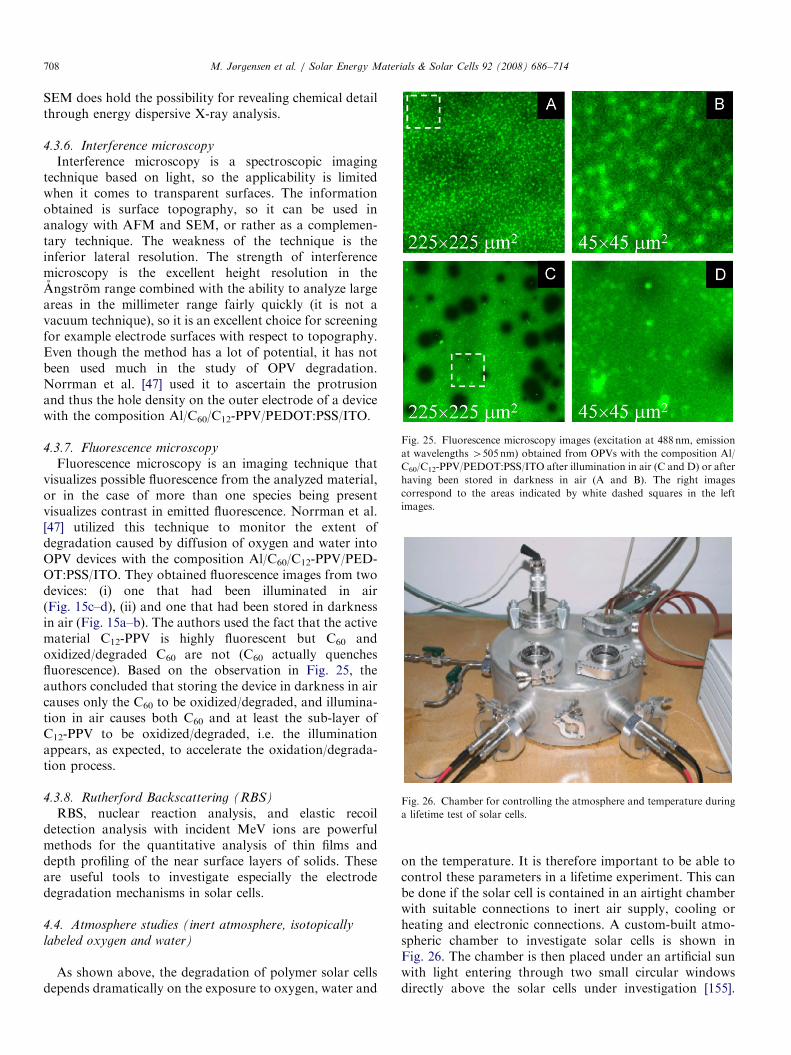
ARTICLE IN PRESS
Fig. 25. Fluorescence microscopy images (excitation at 488 nm, emission
at wavelengths 4505nm) obtained from OPVs with the composition Al/
C60/C12-PPV/PEDOT:PSS/ITO after illumination in air (C and D) or after
having been stored in darkness in air (A and B). The right images
correspond to the areas indicated by white dashed squares in the left
images.
Fig. 26. Chamber for controlling the atmosphere and temperature during
a lifetime test of solar cells.
M. Jørgensen et al. / Solar Energy Materials & Solar Cells 92 (2008) 686–714708
SEM does hold the possibility for revealing chemical detailthrough energy dispersive X-ray analysis.
4.3.6. Interference microscopy
Interference microscopy is a spectroscopic imagingtechnique based on light, so the applicability is limitedwhen it comes to transparent surfaces. The informationobtained is surface topography, so it can be used inanalogy with AFM and SEM, or rather as a complemen-tary technique. The weakness of the technique is theinferior lateral resolution. The strength of interferencemicroscopy is the excellent height resolution in theAngstrom range combined with the ability to analyze largeareas in the millimeter range fairly quickly (it is not avacuum technique), so it is an excellent choice for screeningfor example electrode surfaces with respect to topography.Even though the method has a lot of potential, it has notbeen used much in the study of OPV degradation.Norrman et al. [47] used it to ascertain the protrusionand thus the hole density on the outer electrode of a devicewith the composition Al/C60/C12-PPV/PEDOT:PSS/ITO.
4.3.7. Fluorescence microscopy
Fluorescence microscopy is an imaging technique thatvisualizes possible fluorescence from the analyzed material,or in the case of more than one species being presentvisualizes contrast in emitted fluorescence. Norrman et al.[47] utilized this technique to monitor the extent ofdegradation caused by diffusion of oxygen and water intoOPV devices with the composition Al/C60/C12-PPV/PED-OT:PSS/ITO. They obtained fluorescence images from twodevices: (i) one that had been illuminated in air(Fig. 15c–d), (ii) and one that had been stored in darknessin air (Fig. 15a–b). The authors used the fact that the activematerial C12-PPV is highly fluorescent but C60 andoxidized/degraded C60 are not (C60 actually quenchesfluorescence). Based on the observation in Fig. 25, theauthors concluded that storing the device in darkness in aircauses only the C60 to be oxidized/degraded, and illumina-tion in air causes both C60 and at least the sub-layer ofC12-PPV to be oxidized/degraded, i.e. the illuminationappears, as expected, to accelerate the oxidation/degrada-tion process.
4.3.8. Rutherford Backscattering (RBS)
RBS, nuclear reaction analysis, and elastic recoildetection analysis with incident MeV ions are powerfulmethods for the quantitative analysis of thin films anddepth profiling of the near surface layers of solids. Theseare useful tools to investigate especially the electrodedegradation mechanisms in solar cells.
4.4. Atmosphere studies (inert atmosphere, isotopically
labeled oxygen and water)
As shown above, the degradation of polymer solar cellsdepends dramatically on the exposure to oxygen, water and
on the temperature. It is therefore important to be able tocontrol these parameters in a lifetime experiment. This canbe done if the solar cell is contained in an airtight chamberwith suitable connections to inert air supply, cooling orheating and electronic connections. A custom-built atmo-spheric chamber to investigate solar cells is shown inFig. 26. The chamber is then placed under an artificial sunwith light entering through two small circular windowsdirectly above the solar cells under investigation [155].
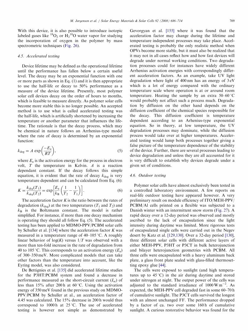
ARTICLE IN PRESSM. Jørgensen et al. / Solar Energy Materials & Solar Cells 92 (2008) 686–714 709
With this device, it is also possible to introduce isotopiclabeled gases like 18O2 or H2
18O water vapor for studyingthe incorporation of oxygen in the polymer by massspectrometric techniques (Fig. 26).
4.5. Accelerated testing
Device lifetime may be defined as the operational lifetimeuntil the performance has fallen below a certain usefullevel. The decay may be an exponential function with oneor more parts as shown in Eq. (1) and it is then appropriateto use the half-life or decay to 50% performance as ameasure of the device lifetime. Presently, most polymersolar cell devices decay on the order of hours to months,which is feasible to measure directly. As polymer solar cellsbecome more stable this is no longer possible. An acceptedmethod is to use what is called accelerated testing wasthe half-life, which is artificially shortened by increasing thetemperature or another parameter that influences the life-time. The rationale is that the decay process, which maybe chemical in nature follows an Arrhenius-type modelwhere the rate of decay is determined by an exponentialfunction:
kdeg ¼ A exp�Ea
RT
� �, (5)
where Ea is the activation energy for the process in electronvolt, T the temperature in Kelvin. A is a reactiondependant constant. If the decay follows this simpleequation, it is evident that the rate of decay kdeg is verytemperature dependent and can be calculated from Eq. (6):
K ¼kdegðT1Þ
kdegðT2Þ¼ exp
Ea
kB
1
T2�
1
T1
� �� �. (6)
The acceleration factor K is the ratio between the rates ofdegradation (kdeg) at the two temperatures (T1 and T2) andkB is the Boltzmann constant. The model is rathersimplified. For instance, if more than one decay mechanismis operating they should all follow Eq. (5). The acceleratedtesting has been applied to MDMO-PPV/PCBM solar cellsby Schuller et al. [134] where the acceleration factor K wasmeasured in a temperature range of 40–105 1C. A roughlylinear behavior of log(K) versus 1/T was observed with amore than ten-fold increase in the rate of degradation from40 to 105 1C. This corresponds to an activation energy (Ea)of 300–350meV. More complicated models that can takeother factors than the temperature into account, like theEyring model, was also considered.
De Bettignies et al. [135] did accelerated lifetime studiesfor the P3HT:PCBM system and found a decrease inperformance measured as the short-circuit current (Isc) ofless than 15% after 200 h at 60 1C. Using the activationenergy of 350meV found in the previous study on MDMO-PPV/PCBM by Schuller at al., an acceleration factor of4.45 was calculated. The 15% decrease in 200 h would thuscorrespond to 1000 h at 25 1C. The use of acceleratedtesting is however not simple as demonstrated by
Gevorgyan et al. [155] where it was found that theacceleration factor may change during the lifetime andtemperature independent processes may take place. Accel-erated testing is probably the only realistic method whenOPVs become more stable, but it must also be realized thatit may not in all cases reflect how and how fast devices willdegrade under normal working conditions. Two degrada-tion processes could for instances have widely differentArrhenius activation energies with correspondingly differ-ent acceleration factors. As an example, take UV lightdegradation where light of 400 nm has an energy of 3 eVwhich is a lot of energy compared with the ordinarytemperature scale where operation is at or around roomtemperature. Heating the sample by an extra 50–60 1Cwould probably not affect such a process much. Degrada-tion by diffusion on the other hand depends on thediffusion coefficient of the chemical species responsible forthe decay. This diffusion coefficient is temperaturedependent according to an Arhenius-type exponentialequation. So in theory, at low temperature, the UVdegradation processes may dominate, while the diffusionprocess would take over at higher temperatures. Acceler-ated testing would lump both processes together giving afalse picture of the temperature dependence of the stabilityof the device. Further, there are several processes leading todevice degradation and unless they are all accounted for itis very difficult to establish why devices degrade under agiven set of conditions.
4.6. Outdoor testing
Polymer solar cells have almost exclusively been tested ina controlled laboratory environment. A few reports onreal-life outdoor testing have appeared however. A verypreliminary result on module efficiency of ITO/MEH-PPV/PCBM/Al cells printed on a flexible was subjected to aDanish winter with an intermittent snow storm (Fig. 27). Arapid decay over a 12-day period was observed and mostlyascribed to the lack of encapsulation since the lightintensity during daytime was limited. More rigorous testsof encapsulated single cells were carried out in the Negevdesert by Katz et al. [129,130]. Over a 32-day period [130],three different solar cells with different active layers ofeither MEH-PPV, P3HT or P3CT in bulk heterojunctionand bilayer heterojunction geometries with PCBM. Allthree cells were encapsulated with a heavy aluminum backplate, a glass front plate sealed with glass-filled thermoset-ting epoxy glue [44].The cells were exposed to sunlight (and high tempera-
tures up to 45 1C) in the air during daytime and storedunder nitrogen at night. The output power of the cells wasadjusted to the standard irradiance of 1000Wm�2. Asexpected, the MEH-PPV cell degraded fast in some 60–70 hof cumulative sunlight. The P3CT cells survived the longestwith an almost unchanged FF. The performance droppedby a factor of ca. two over some 160 h of cumulativesunlight. A curious restorative behavior was found for the
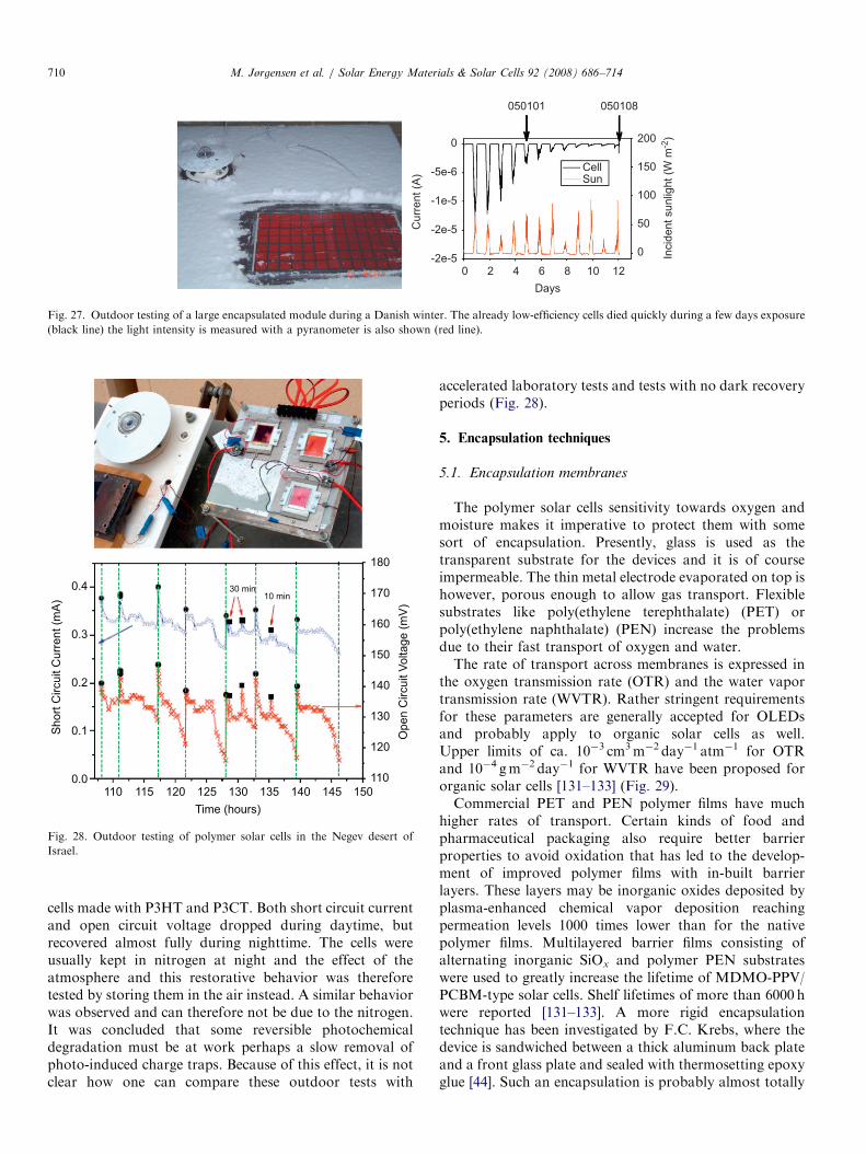
ARTICLE IN PRESS
Days0
Cur
rent
(A)
-2e-5
-2e-5
-1e-5
-5e-6
0
Inci
dent
sun
light
(W m
-2)
0
50
100
150
200
CellSun
050101 050108
2 4 6 8 10 12
Fig. 27. Outdoor testing of a large encapsulated module during a Danish winter. The already low-efficiency cells died quickly during a few days exposure
(black line) the light intensity is measured with a pyranometer is also shown (red line).
0.4
0.3
0.2
0.1
0.0110 115 120 125 130 135 140 145 150
Time (hours)
Sho
rt C
ircui
t Cur
rent
(mA
)
30 min10 min
180
170
160
150
140
130
120
110
Ope
n C
ircui
t Vol
tage
(mV
)
Fig. 28. Outdoor testing of polymer solar cells in the Negev desert of
Israel.
M. Jørgensen et al. / Solar Energy Materials & Solar Cells 92 (2008) 686–714710
cells made with P3HT and P3CT. Both short circuit currentand open circuit voltage dropped during daytime, butrecovered almost fully during nighttime. The cells wereusually kept in nitrogen at night and the effect of theatmosphere and this restorative behavior was thereforetested by storing them in the air instead. A similar behaviorwas observed and can therefore not be due to the nitrogen.It was concluded that some reversible photochemicaldegradation must be at work perhaps a slow removal ofphoto-induced charge traps. Because of this effect, it is notclear how one can compare these outdoor tests with
accelerated laboratory tests and tests with no dark recoveryperiods (Fig. 28).
5. Encapsulation techniques
5.1. Encapsulation membranes
The polymer solar cells sensitivity towards oxygen andmoisture makes it imperative to protect them with somesort of encapsulation. Presently, glass is used as thetransparent substrate for the devices and it is of courseimpermeable. The thin metal electrode evaporated on top ishowever, porous enough to allow gas transport. Flexiblesubstrates like poly(ethylene terephthalate) (PET) orpoly(ethylene naphthalate) (PEN) increase the problemsdue to their fast transport of oxygen and water.The rate of transport across membranes is expressed in
the oxygen transmission rate (OTR) and the water vaportransmission rate (WVTR). Rather stringent requirementsfor these parameters are generally accepted for OLEDsand probably apply to organic solar cells as well.Upper limits of ca. 10�3 cm3m�2 day�1 atm�1 for OTRand 10�4 gm�2 day�1 for WVTR have been proposed fororganic solar cells [131–133] (Fig. 29).Commercial PET and PEN polymer films have much
higher rates of transport. Certain kinds of food andpharmaceutical packaging also require better barrierproperties to avoid oxidation that has led to the develop-ment of improved polymer films with in-built barrierlayers. These layers may be inorganic oxides deposited byplasma-enhanced chemical vapor deposition reachingpermeation levels 1000 times lower than for the nativepolymer films. Multilayered barrier films consisting ofalternating inorganic SiOx and polymer PEN substrateswere used to greatly increase the lifetime of MDMO-PPV/PCBM-type solar cells. Shelf lifetimes of more than 6000 hwere reported [131–133]. A more rigid encapsulationtechnique has been investigated by F.C. Krebs, where thedevice is sandwiched between a thick aluminum back plateand a front glass plate and sealed with thermosetting epoxyglue [44]. Such an encapsulation is probably almost totally
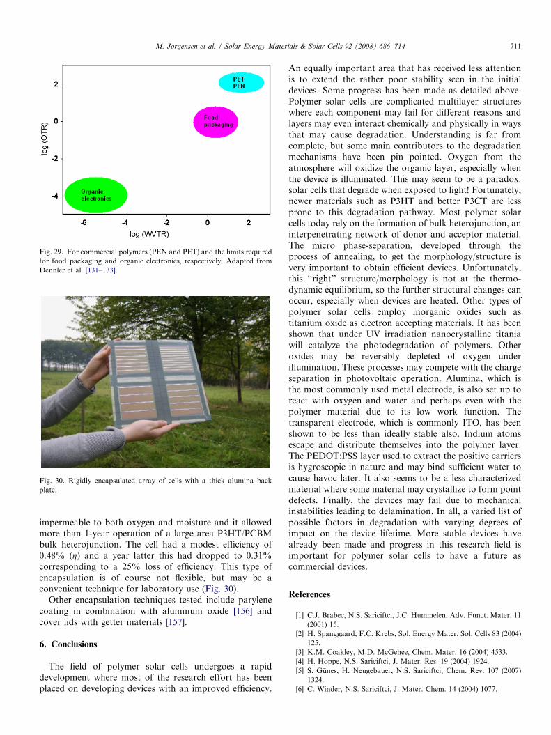
ARTICLE IN PRESS
Fig. 29. For commercial polymers (PEN and PET) and the limits required
for food packaging and organic electronics, respectively. Adapted from
Dennler et al. [131–133].
Fig. 30. Rigidly encapsulated array of cells with a thick alumina back
plate.
M. Jørgensen et al. / Solar Energy Materials & Solar Cells 92 (2008) 686–714 711
impermeable to both oxygen and moisture and it allowedmore than 1-year operation of a large area P3HT/PCBMbulk heterojunction. The cell had a modest efficiency of0.48% (Z) and a year latter this had dropped to 0.31%corresponding to a 25% loss of efficiency. This type ofencapsulation is of course not flexible, but may be aconvenient technique for laboratory use (Fig. 30).
Other encapsulation techniques tested include parylenecoating in combination with aluminum oxide [156] andcover lids with getter materials [157].
6. Conclusions
The field of polymer solar cells undergoes a rapiddevelopment where most of the research effort has beenplaced on developing devices with an improved efficiency.
An equally important area that has received less attentionis to extend the rather poor stability seen in the initialdevices. Some progress has been made as detailed above.Polymer solar cells are complicated multilayer structureswhere each component may fail for different reasons andlayers may even interact chemically and physically in waysthat may cause degradation. Understanding is far fromcomplete, but some main contributors to the degradationmechanisms have been pin pointed. Oxygen from theatmosphere will oxidize the organic layer, especially whenthe device is illuminated. This may seem to be a paradox:solar cells that degrade when exposed to light! Fortunately,newer materials such as P3HT and better P3CT are lessprone to this degradation pathway. Most polymer solarcells today rely on the formation of bulk heterojunction, aninterpenetrating network of donor and acceptor material.The micro phase-separation, developed through theprocess of annealing, to get the morphology/structure isvery important to obtain efficient devices. Unfortunately,this ‘‘right’’ structure/morphology is not at the thermo-dynamic equilibrium, so the further structural changes canoccur, especially when devices are heated. Other types ofpolymer solar cells employ inorganic oxides such astitanium oxide as electron accepting materials. It has beenshown that under UV irradiation nanocrystalline titaniawill catalyze the photodegradation of polymers. Otheroxides may be reversibly depleted of oxygen underillumination. These processes may compete with the chargeseparation in photovoltaic operation. Alumina, which isthe most commonly used metal electrode, is also set up toreact with oxygen and water and perhaps even with thepolymer material due to its low work function. Thetransparent electrode, which is commonly ITO, has beenshown to be less than ideally stable also. Indium atomsescape and distribute themselves into the polymer layer.The PEDOT:PSS layer used to extract the positive carriersis hygroscopic in nature and may bind sufficient water tocause havoc later. It also seems to be a less characterizedmaterial where some material may crystallize to form pointdefects. Finally, the devices may fail due to mechanicalinstabilities leading to delamination. In all, a varied list ofpossible factors in degradation with varying degrees ofimpact on the device lifetime. More stable devices havealready been made and progress in this research field isimportant for polymer solar cells to have a future ascommercial devices.
References
[1] C.J. Brabec, N.S. Sariciftci, J.C. Hummelen, Adv. Funct. Mater. 11
(2001) 15.
[2] H. Spanggaard, F.C. Krebs, Sol. Energy Mater. Sol. Cells 83 (2004)
125.
[3] K.M. Coakley, M.D. McGehee, Chem. Mater. 16 (2004) 4533.
[4] H. Hoppe, N.S. Sariciftci, J. Mater. Res. 19 (2004) 1924.
[5] S. Gunes, H. Neugebauer, N.S. Sariciftci, Chem. Rev. 107 (2007)
1324.
[6] C. Winder, N.S. Sariciftci, J. Mater. Chem. 14 (2004) 1077.
ARTICLE IN PRESSM. Jørgensen et al. / Solar Energy Materials & Solar Cells 92 (2008) 686–714712
[7] E. Bundgaard, F.C. Krebs, Sol. Energy Mater. Sol. Cells 91 (2007)
954.
[8] B.P. Rand, J. Genoe, P. Heremans, J. Poortmans, Prog. Photovolt.
Res. Appl. 15 (2007) 659.
[9] F.C. Krebs (Ed.), Special Issue: The development of organic and
polymer photovoltaics, Sol. Energy Mater. Sol. Cells 83 (2–3)
(2004).
[10] S.E. Shaheen, D.S. Ginley, G.E. Jabbour (Eds.), Special Issue:
Organic-Based Photovoltaics, MRS Bull 30 (1) (2005).
[11] F.C. Krebs (Ed.), Special Issue: low band gap polymer materials
for organic photovoltaics, Sol. Energy Mater. Sol. Cells 91 (11)
(2007).
[12] M.T. Loyd, J.E. Anthony, C.G. Malliaras (Eds.), Special Issue: a
real alternative. Materials and devices for cheap efficient solar
power, Mater. Today 10 (11) (2007).
[13] J. Poortmans (Ed.), Special Issue. Prog. Photovolt., Res. Appl. 15
(8) (2007).
[14] S.E. Shaheen, D.S. Ginley, G.E. Jabbour, MRS Bull. 30 (2005) 10.
[15] R.A.J. Janssen, J.C. Hummelen, N.S. Sariciftci, MRS Bull. 30
(2005) 33.
[16] K.M. Coakley, Y. Liu, C. Goh, M.D. McGehee, MRS Bull. 30
(2005) 37.
[17] C.J. Brabec, J.A. Hauch, P. Schilinsky, C. Waldauf, MRS Bull. 30
(2005) 50.
[18] A.C. Mayer, S.R. Scully, B.E. Hardin, M.W. Rowell, M.D.
McGehee, Mater. Today 10 (2007) 28.
[19] M.T. Lloyd, J.E. Anthony, G.G. Malliaras, Mater. Today 10 (2007)
34.
[20] J.Y. Kim, K. Lee, N.E. Coates, D. Moses, T.-Q. Nguyen, M. Dante,
A.J. Heeger, Science 317 (2007) 222.
[21] G. Li, V. Shrotriya, J. Huang, Y. Yao, T. Moriarty, K. Emery,
Y. Yang, Nat. Mater. 4 (2005) 864.
[22] W. Ma, C. Yang, X. Gong, K. Lee, A.J. Heeger, Adv. Funct. Mater.
15 (2005) 1617.
[23] S.R. Forrest, MRS Bull. 30 (2005) 28.
[24] L.J.A. Koster, V.D. Mihailetchi, P.W.M. Blom, Appl. Phys. Lett. 88
(2006) 093511.
[25] M.C. Scharber, D. Muhlbacher, M. Koppe, P. Denk, C. Waldauf,
A.J. Heeger, C.J. Brabec, Adv. Mater. 18 (2006) 789.
[26] J. Gilot, M.M. Wienk, R.A.J. Janssen, Nat. Mater. 6 (2007) 704.
[27] (a)G. Dennler, Mater. Today 10 (2007) 56;
(b) G.P. Smestad, F.C. Krebs, C.M. Lampert, C.G. Granquist,
K.L. Chopra, X. Mathew, H. Takakura, Sol. Energ. Mater. Sol.
Cells 92 (2008) 371–373.
[28] C.J. Brabec, Sol. Energy Mater. Sol. Cells 83 (2004) 273.
[29] F.C. Krebs, Refocus 6 (2005) 38.
[30] G. Yu, C. Zhang, A.J. Heeger, Appl. Phys. Lett. 64 (1994) 1540.
[31] H. Hansel, H. Zettl, G. Krausch, R. Kisselev, M. Thelakkat,
H.W. Schmidt, Adv. Mater. 15 (2003) 2056.
[32] ASTM International, Standard Tables for Reference Solar Spectral
Irradiances: Direct Normal and Hemispherical on 371 Tilted
Surface, G 173-03, 2003. The data can be downloaded at;
/http://rredc.nrel.gov/solar/spectra/am1.5/S.
[33] ASTM International, Standard Specification for solar simulation for
photovoltaic testing, E 927-05, 2005.
[34] IEC 904-9, Photovoltaic devices—Part 9: Solar simulator perfor-
mance requirements, 1995, IEC 904-9:1995(E).
[35] (a)A. Moliton, J.-M. Nunzi, Polym. Int. 55 (2006) 583;
(b) S.E. Shaheen, Reliability physics symposium, 15–19 (2007) 248–
252. (doi:10.1109/RELPHY.2007.369900).
[36] F.C. Krebs, J.E. Carle, N. Cruys-Bagger, M. Andersen,
M.R. Lilliedal, M.A. Hammond, S. Hvidt, Sol. Energy Mater.
Sol. Cells 86 (2005) 499.
[37] C. Fery, B. Racine, D. Vaufrey, H. Doyeux, S. Cina, Appl. Phys.
Lett. 87 (2005) 213502.
[38] N. Chawdhury, A. Kohler, M.G. Harrison, D.H. Hwang,
A.B. Holmes, R.H. Friend, Synth. Met. 102 (1999) 871.
[39] B.M. Henry, F. Dinelli, K.-Y. Zhao, C.R.M. Grovenor,
O.V. Kolosov, G.A.D. Briggs, A.P. Roberts, R.S. Kumar,
R.P. Howson, Thin Solid Films 355–356 (1999) 500.
[40] A.G. Erlat, B.M. Henry, J.J. Ingram, D.B. Mountain,
A. McGuigan, R.P. Howson, C.R.M. Grovenor, G.A.D. Briggs,
Y. Tsukahara, Thin Solid Films 388 (2001) 78.
[41] M. Yanaka, B.M. Henry, A.P. Roberts, C.R.M. Grovenor,
G.A.D. Briggs, A.P. Sutton, T. Miyamoto, Y. Tsukahara,
N. Takeda, R.J. Chater, Thin Solid Films 397 (2001) 176.
[42] A.P. Roberts, B.M. Henry, A.P. Sutton, C.R.M. Grovenor,
G.A.D. Briggs, T. Miyamoto, M. Kano, Y. Tsukahara, M. Yanaka,
J. Membr. Sci. 208 (2002) 75.
[43] A.G. Erlat, B.M. Henry, C.R.M. Grovenor, A.G.D. Briggs,
R.J. Chater, Y. Tsukahara, J. Phys. Chem. B 108 (2004) 883.
[44] F.C. Krebs, Sol. Energy Mater. Sol. Cells 90 (2006) 3633.
[45] K. Norrman, F.C. Krebs, Surf. Interface Anal. 36 (2004) 1542.
[46] K. Norrman, F.C. Krebs, Sol. Energy Mater. Sol. Cells 90 (2006)
213.
[47] K. Norrman, N.B. Larsen, F.C. Krebs, Sol. Energy Mater. Sol.
Cells 90 (2006) 2793.
[48] M. Lira-Cantu, K. Norrman, J.W. Andreasen, F.C. Krebs, Chem.
Mater. 18 (2006) 5684.
[49] K. Norrman, F.C. Krebs, Proc. SPIE 5938 (59380D) (2005) 1.
[50] F.C. Krebs, K. Norrman, Prog. Photovol. Res. Appl. 15 (2007) 697.
[51] K. Norrman, J. Alstrup, M. Jørgensen, N.B. Larsen, M. Lira-
Cantu, F.C. Krebs, Proc. SPIE 6334 (63340O) (2006).
[52] D.L. Rode, V.R. Gaddam, J.H. Yi, J. Appl. Phys. 102 (2007)
024303.
[53] R.D. Scurlock, B. Wang, P.R. Ogilby, J.R. Sheats, R.L. Clough,
J. Am. Chem. Soc. 117 (1995) 10194.
[54] N. Dam, R.D. Scurlock, B. Wang, L. Ma, M. Sundahl, P.R. Ogilby,
Chem. Mater. 11 (1999) 1302.
[55] B.H. Cumpston, K.F. Jensen, J. Appl. Polym. Sci. 69 (1998) 2451.
[56] R.F. Bianchi, D.T. Balogh, M. Tinani, R.M. Faria, E.A. Irene,
J. Polym. Sci. Part B: Polym. Phys. 42 (2004) 1033.
[57] H. Neugebauer, C.J. Brabec, J.C. Hummelen, R.A.J. Janssen,
N.S. Sariciftci, Synth. Met. 102 (1999) 1002.
[58] H. Neugebauer, C.J. Brabec, J.C. Hummelen, N.S. Sariciftci, Sol.
Energy Mater. Sol. Cells 61 (2000) 35.
[59] F. Padinger, T. Fromherz, P. Denk, C.J. Brabec, J. Zettner, T. Hierl,
N.S. Sariciftci, Synth. Met. 121 (2001) 1605.
[60] S. Chambon, A. Rivaton, J.-L. Gardette, M. Firon, Sol. Energy
Mater. Sol. Cells 91 (2007) 394.
[61] S. Chambon, A. Rivaton, J.-L. Gardette, M. Firon, L. Lutzen,
J. Pol. Sci. Part A: Pol. Chem. 45 (2007) 317.
[62] J. Alstrup, K. Norrman, M. Jørgensen, F.C. Krebs, Sol. Energy
Mater. Sol. Cells 90 (2006) 2777.
[63] K. Norrman, J. Alstrup, M. Jørgensen, F.C. Krebs, Surf. Interface
Anal. 38 (2006) 1302.
[64] M.S.A. Abdou, F.P. Orfino, Y. Son, S. Holdcroft, J. Am. Chem.
Soc. 119 (1997) 4518.
[65] M.G. Matturro, R.P. Reynolds, R.V. Kastrup, C.F. Pictroski,
J. Am. Chem. Soc. 108 (1986) 2775.
[66] L. Luer, H.-J. Egelhaaf, D. Oelkrug, G. Cerullo, G. Lanzani,
B.-H. Huisman, D. de Leeuw, Org. Electr. 5 (2004) 83.
[67] R. de Bettignies, J. Leroy, S. Chambon, M. Firon, C. Sentein,
L. Sicot, L. Lutzen, Proc. SPIE 5464 (2004) 122.
[68] R. de Bettignies, J. Leroy, S. Chambon, M. Firon, C. Sentein,
L. Sicot, L. Lutzen, Proc. SPIE 5520 (2004) 216.
[69] F.C. Krebs, R.B. Nyberg, M. Jørgensen, Chem. Mater. 16 (2004)
1313.
[70] K.T. Nielsen, K. Bechgaard, F.C. Krebs, Macromolecules 38 (2005)
658.
[71] K.T. Nielsen, K. Bechgaard, F.C. Krebs, Synthesis (2006) 1639.
[72] K.T. Nielsen, P. Harris, K. Bechgaard, F.C. Krebs, Acta Crystal-
logr. B 63 (2007) 151.
[73] M.M. Wienk, M.P. Struijk, R.A.J. Janssen, Chem. Phys. Lett. 422
(2006) 488.
ARTICLE IN PRESSM. Jørgensen et al. / Solar Energy Materials & Solar Cells 92 (2008) 686–714 713
[74] B.C. O’Regan, M. Gratzel, Nature 353 (1991) 737.
[75] L. Xiao-e, A.N.M. Green, S.A. Haque, A. Mills, J.R. Durrant,
J. Photochem. J. Photobiol. A: Chem. 162 (2004) 253.
[76] A.M. Peiro, G. Doyle, A. Mills, J.R. Durrant, Adv. Mater. 17
(2005) 2365.
[77] A. Mills, G. Doyle, A.M. Peiro, J. Durrant, J. Photochem.
J. Photobiol. A: Chem. 177 (2006) 328.
[78] A.M. Peiro, C. Colombo, G. Doyle, J. Nelson, A. Mills,
J.R. Durant, J. Phys. Chem. B 110 (2006) 23255.
[79] P. Ravirajan, S.A. Haque, J.R. Durrant, D. Poplavskyy,
D.D.C. Bradley, J. Nelson, J. Appl. Phys. 95 (2004) 1473.
[80] P. Ravirajan, S.A. Haque, D. Poplavskyy, J.R. Durrant,
D.D.C. Bradley, J. Nelson, Thin Solid Films 451–452 (2004) 624.
[81] P. Ravirajan, D.D.C. Bradley, J. Nelson, S.A. Haque, J.R. Durrant,
H.J.P. Smit, J.M. Kroon, Appl. Phys. Lett. 86 (2005) 143101.
[82] P. Ravirajan, S.A. Haque, J.R. Durrant, D.D.C. Bradley, J. Nelson,
Adv. Funct. Mater. 15 (2005) 609.
[83] M. Lira-Cantu, F.C. Krebs, Sol. Energy Mater. Sol. Cells 90 (2006)
2076.
[84] M. Lira-Cantu, K. Norrman, J.W. Andreasen, N. Casan-Pastor,
F.C. Krebs, J. Electrochem. Soc. 154 (2007) B508.
[85] W.J.E. Beek, M.M. Wienk, M. Kemerink, X. Yang, R.A.J. Janssen,
J. Phys. Chem. B 109 (2005) 9505.
[86] D.C. Olson, J. Piris, R.T. Collins, S.E. Shaheen, D.S. Ginley, Thin
Solid Films 496 (2006) 26.
[87] W.J.E. Beek, M.M. Wienk, R.A.J. Janssen, Adv. Funct. Mater. 16
(2006) 1112.
[88] H. Aziz, G. Xu, Synth. Met. 80 (1996) 7.
[89] H. Aziz, Z.D. Popovic, N.-X. Hu, A. Hor, G. Xu, Science 283 (1999)
1900.
[90] H. Aziz, Z.D. Popovic, Chem. Mater. 16 (2004) 4522.
[91] M. Logdlund, J.L. Bredas, J. Chem. Phys. 101 (1994) 4357.
[92] M. Fahlman, D. Beljonne, M. Logdlund, R.H. Friend,
A.B. Holmes, J.L. Bredas, W.R. Salaneck, Chem. Phys. Lett. 214
(1993) 327.
[93] M. Fahlman, P. Broms, D.A. dos Santos, S.C. Moratti,
N. Johansson, K. Xing, R.H. Friend, A.B. Holmes, J.L. Bredas,
W.R. Salaneck, J. Chem. Phys. 102 (1995) 8167.
[94] H. Antoniadis, B.R. Hsieh, M.A. Abkowitz, S.A. Jenekhe,
M. Stolka, Synth. Met. 62 (1994) 265.
[95] S. Gamerith, C. Gadermaier, H.-G. Nothofer, U. Scherf,
E.J.W. List, Proc. SPIE 5464 (2004) 104.
[96] S. Cros, M. Firon, S. Lenfant, P. Trouslard, L. Beck, Nucl. Inst.
Meth. Phys. Res. B 251 (2006) 257.
[97] C. Melzer, V.V. Krasnikov, G. Hadziioannou, Appl. Phys. Lett. 82
(2003) 3101.
[98] J. Nishnaga, T. Aihara, H. Yamagata, Y. Horikoshi, J. Cryst.
Growth 278 (2005) 633.
[99] M. Vogel, S. Doka, Ch. Breyer, M.Ch. Lux-Steiner, K. Fostir-
opoulos, Appl. Phys. Lett. 89 (2006) 163501.
[100] F. Li, H. Tang, J. Anderegg, J. Shinar, Appl. Phys. Lett. 70 (1997)
1233.
[101] S.T. Zhang, Y.C. Zhou, J.M. Zhao, Y.Q. Zhan, Z.J. Wang, Y. Wu,
X.M. Ding, X.Y. Hou, Appl. Phys. Lett. 89 (2006) 043502.
[102] L.S. Hung, C.W. Tang, M.G. Mason, Appl. Phys. Lett. 70 (1997)
152.
[103] C.J. Brabec, S.E. Shaheen, C. Winder, N.S. Sariciftci, Appl. Phys.
Lett. 80 (2002) 1288.
[104] W.J.H. van Gennip, J.K.J. van Duren, P.C. Thune, R.A. Janssen,
J.W. Niemantsverdriet, J. Chem. Phys. 117 (2002) 5031.
[105] N. Karst, J.C. Bernede, Phys. Stat. Sol. A 203 (2006) R70.
[106] F.C. Krebs, H. Spanggaard, Chem. Mater. 17 (2005) 5235.
[107] M. Bjerring, J.S. Nielsen, A. Siu, N. Chr. Nielsen, F.C. Krebs,
Sol. Energy Mater. Sol. Cells 92 (2008) 782–794, this issue;
doi:10.1016/j.solmat.2007.11.008.
[108] M. Glatthaar, M. Riede, N. Keegan, K. Sylvester-Hvid,
B. Zimmermann, M. Niggemann, A. Hinsch, A. Gombert, Sol.
Energy Mater. Sol. Cells 91 (2007) 390.
[109] M. Glatthaar, N. Mingirullim, B. Zimmermann, T. Ziegler,
R. Kern, M. Niggemann, A. Hinsch, A. Gombert, Phys. Stat. Sol.
A 202 (2005) R125.
[110] B. Paci, A. Generosi, V.R. Albertini, P. Perfetti, B. de Bettignies,
M. Firon, J. Leroy, C. Sentein, Appl. Phys. Lett. 87 (2005) 194110.
[111] B. Paci, A. Generosi, V.R. Albertini, P. Perfetti, B. de Bettignies,
M. Firon, J. Leroy, C. Sentein, Appl. Phys. Lett. 89 (2006) 043507.
[112] J.W. Andreasen, S. Gevorgyan, C.M. Schlepuetz, F.C. Krebs, Sol.
Energy Mater. Sol. Cells 92 (2008) 803–808, this issue; doi:10.1016/
j.solmat.2008.02.011.
[113] M.P. de Jong, L.J. van Ijzendoorn, M.J.A. de Voigt, Appl. Phys.
Lett. 77 (2000) 2255.
[114] R. Pacios, A.J. Chatten, K. Kawano, J.R. Durrant, D.D.C. Bradley,
J. Nelson, Adv. Funct. Mater. 16 (2006) 2117.
[115] K. Kawano, R. Pacios, D. Poplavskyy, J. Nelson, D.D.C. Bradley,
J.R. Durrant, Sol. Energy Mater. Sol. Cells 90 (2006) 3520.
[116] J.S. Liu, E.N. Kadnikova, Y.X. Liu, M.D. McGehee,
J.M.J. Frechet, J. Am. Chem. Soc. 126 (2004) 9486.
[117] F.C. Krebs, Proc. SPIE 5938 (2005) 59380Y.
[118] X. Yang, J. Loos, S.C. Veenstra, W.J.H. Verhees, M.M. Wienk,
J.M. Kroon,M.A.J. Michels, R.A.J. Janssen, Nano Letters 5 (2005) 579.
[119] F.C. Krebs, J. Alstrup, H. Spanggaard, K. Larsen, E. Kold, Sol.
Energy Mater. Sol. Cells 83 (2004) 293.
[120] E. Bundgaard, F.C. Krebs, Pol. Bull. 55 (2005) 157.
[121] F.C. Krebs, J. Alstrup, M. Biancardo, H. Spanggaard, Proc. SPIE
5938 (2005) 593804.
[122] F.C. Krebs, M. Biancardo, B. Winther-Jensen, H. Spanggaard,
J. Alstrup, 90 (2006) 1058.
[123] B. Winther-Jensen, F.C. Krebs, Sol. Energy Mater. Sol. Cells 90
(2006) 123.
[124] F.C. Krebs, H. Spanggaard, T. Kjær, M. Biancardo, J. Alstrup,
Mater. Sci. Eng. B 138 (2007) 106.
[125] E. Bundgaard, F.C. Krebs, Sol. Energy Mater. Sol. Cells 91 (2007)
1019.
[126] M.H. Petersen, O. Hagemann, K.T. Nielsen, M. Jørgensen,
F.C. Krebs, Sol. Energy Mater. Sol. Cells 91 (2007) 996.
[127] M. Andersen, J.E. Carle, N. Cruys-Bagger, M.R. Lilliedal,
M.A. Hammond, B. Winther-Jensen, F.C. Krebs, Sol. Energy
Mater. Sol. Cells 91 (2007) 539.
[128] T. Jeranko, H. Tributsch, N.S. Sariciftci, J.C. Hummelen, Sol.
Energy Mater. Sol. Cells 83 (2004) 247.
[129] E.A. Katz, D. Faiman, S.M. Tuladhar, J.M. Kroon, M.M. Wienk,
T. Fromherz, F. Padinger, C.J. Brabec, N.S. Sariciftci, J. Appl.
Phys. 90 (2001) 5343.
[130] E.A. Katz, S. Gevorgyan, M.S. Orynbayev, F.C. Krebs, Eur.
J. Appl. Phys. 36 (2007) 307.
[131] G. Dennler, C. Lungenschmied, H. Neugebauer, N.S. Sariciftci,
A. Labouret, J. Mater. Res. 20 (2005) 3224.
[132] G. Dennler, C. Lungenschmied, H. Neugebauer, N.S. sariciftci,
M. Latreche, G. Czeremuzkin, M.R. Wertheimer, Thin Solid Films
511–512 (2006) 349.
[133] C. Lungenschmied, G. Dennler, H. Neugebauer, N.S. Sariciftci,
M. Glatthaar, T. Meyer, A. Meyer, Sol. Energy Mater. Sol. Cells 91
(2007) 379.
[134] S. Schuller, P. Schilinsky, J. Hauch, C.J. Brabec, Appl. Phys. A 79
(2004) 37.
[135] R. De Bettignies, F. Leroy, M. Firon, C. Sentein, Synth. Met. 156
(2006) 510.
[136] G.C.M. Silvestre, M.T. Johnson, A. Giraldo, J.M. Shannon, Appl.
Phys. Lett. 78 (2001) 1619.
[137] Y. Sahin, S. Alem, R. de Bettignies, J.-M. Nunzi, Thin Solid Films
476 (2005) 340.
[138] (a) F.C. Krebs, Sol. Energy Mater. Sol. Cells 92 (2008) 725–736,
this issue; doi:10.1016/j.solmat.2008.01.013;
(b) K. Lee, J.Y. Kim, S.H. Park, S.H. Kim, S. Cho, A.J. Heeger,
Adv. Mater. 19 (2007) 2445;
(c) B. Fan, R. Hany, J.-E. Moser, F. Nuesch, Org. Electron. 9
(2008) 85.
ARTICLE IN PRESSM. Jørgensen et al. / Solar Energy Materials & Solar Cells 92 (2008) 686–714714
[139] G. Yu, J. Gao, J.C. Hummelen, F. Wudl, A.J. Heeger, Science 270
(1995) 1789.
[140] X. Yang, J.K.J. van Duren, R.A.J. Janssen, M.A.J. Michels,
J. Loos, Macromolecules 37 (2004) 2151.
[141] S. Bertho, I. Haeldermans, A. Swinnen, W. Moons, T. Martens,
L. Lutsen, D. Vanderzande, J. Manca, A. Senes, A. Bonfiglio, Sol.
Energy Mater. Sol. Cells 91 (2007) 385.
[142] R.J. Kline, M.D. McGehee, E.N. Kadnikova, J. Liu, J.M.J. Frechet,
M.F. Toney, Macromolecules 38 (2005) 3312.
[143] E. Klimov, W. Li, X. Yang, G.G. Hoffmann, J. Loos, Macro-
molecules 39 (2006) 4493.
[144] X. Yang, J. Loos, Macromolecules 40 (2007) 1354.
[145] S. Berson, R. de Bettignies, S. Baillo, S. Guillerez, Adv. Funct.
Mater. 17 (2007) 1377.
[146] K. Sivula, C.K. Luscombe, B.C. Thompson, J.M.J. Frechet, J. Am.
Chem. Soc. 128 (2006) 13988.
[147] B. Pradhan, A.J. Pal, Chem. Phys. Lett. 416 (2005) 327.
[148] J.M. Kroon, M.M. Wienk, W.J.H. Verhees, J.C. Hummelen, Thin
Solid Films 403 (2002) 223.
[149] C.R. McNeill, C.J.R. Fell, J.L. Holdsworth, P.C. Dastoor, Synth.
Met. 153 (2005) 85.
[150] C.W.T. Bulle-Lieuwma, W.J.H. van Gennip, J.K.J. van Duren, P.
Jonkheijm, R.A.J. Janssen, J.W. Niemantsverdriet, Appl. Surf. Sci.
203 (2003) 547.
[151] C.W.T. Bulle-Lieuwma, J.K.J. van Duren, X. Jang, J. Loos, A.B. Sieval,
J.C. Hummelen, R.A.J. Janssen, Appl. Surf. Sci. 231 (2004) 274.
[152] J.K.J. van Duren, X. Jang, J. Loos, C.W.T. Bulle-Lieuwma,
A.B. Sieval, J.C. Hummelen, R.A.J. Janssen, Adv. Funct. Mater.
14 (2004) 425.
[153] W. Bijnens, J. Manca, T.-D. Wu, M. D’Olieslaeger, D. Vander-
zande, J. Gelan, W. de Ceuninck, L. de Schepper, L.M. Stals, Synth.
Met. 83 (1996) 261.
[154] H. Heil, J. Steiger, S. Kart, M. Gastel, H. Ortner, H. von Seggern,
M. Stobel, J. Appl. Phys. 89 (2001) 420.
[155] S. Gevorgyan, M. Jørgensen, F.C. Krebs, this issue.
[156] P. Madakasira, K. Inoue, R. Ulbricht, S.B. Lee, M. Zhou,
J.P. Ferraris, A.A. Zakhidov, Synth. Met. 155 (2005) 332.
[157] E.A. Meulenkamp, R. van Aar, J.J.A.M. Bastiaansen, A.J.M. van
den Biggelaar, H. Borner, K. Brunner, M. Buchel, A. van Dijken,
N.M.M. Kiggen, M. Kilitziraki, M.M. de Kok, B.M.W. Langeveld,
M.P.H. Ligter, S.I.E. Vulto, P. van de Weijer, S.H.P.M. Winter,
Proc. SPIE 5464 (2004) 90.
![Polymer Degradation and Stability - University of …...Polymer Degradation and Stability 121 (2015) 407e419 life of more than 50 years, ideally with minimal maintenance [3]. Long-term](https://img.pdfslide.us/doc/110x75/5f71c739b408e14ffb447e7d/polymer-degradation-and-stability-university-of-polymer-degradation-and-stability.jpg)


![Polymer Degradation and Stability · 2019-10-30 · Polymer Degradation and Stability 170 (2019) 108998 (POSS),andalumina-coatedsilica[23].Zirconiumphosphatepaired with PDDA increased](https://img.pdfslide.us/doc/110x75/5f71c4d7090ec208f5729555/polymer-degradation-and-stability-2019-10-30-polymer-degradation-and-stability.jpg)

![Polymer Degradation and Stability · 2019-04-11 · Polymer Degradation and Stability 95 (2010) 2126e2146. ... improved characteristics compared to their individual components [12].Asamatteroffact,naturalbonematrixisanorganic/inorganic](https://img.pdfslide.us/doc/110x75/5f1202493849b60c8e74f2d6/polymer-degradation-and-2019-04-11-polymer-degradation-and-stability-95-2010.jpg)