Embed Size (px)
Citation preview
Review of NZ Building Codes of Practice
By Gregory MacRae Charles Clifton
Les Megget
August 2011
Report to the Royal Commission of Inquiry into the Building Failure
Caused by the Christchurch Earthquakes
ENG.ACA.0016.1
ii
EXECUTIVE SUMMARY This document, prepared for the Royal Commission of Inquiry into the Building Failure Caused by the Christchurch Earthquakes, provides identification, comparison and reference of historical New Zealand standards and codes used in the design of structural steel and structural concrete commercial buildings for earthquake resistance from 1935 to 2010. It is written for engineers/building owners so that they can identify potential weaknesses in buildings designed to previous standards, in comparison to structures designed according to 2010 standards. It also identifies some potential weaknesses in design standards used in 2010. A work of caution is however necessary, because comparison of one or two requirements alone may not give a complete indication of the likely change in building design. For example, an increased strength requirement may have no effect if designs are in fact governed by stiffness. Also, some factors may cancel out. For example, an increase in seismic force together with a change from Working Stress Design to Limit State Design, may result in the same member sizes. For guidance on interpreting the changes listed in this report the reader is recommended to Fenwick and MacRae (2009) for concrete structures, where the combination of these effects is considered. In order to perform the work requested, and to provide context, the report is written in the following format. Chapter 1 provides an overview of the development of standards in New Zealand and the popular NZ forms of construction over time. Then, the different issues addressed by the standards are described in a simple way in Chapter 2. This includes earthquake loading, design assumptions and modelling assumptions. Chapter 3 describes, how different issues have been addressed by the different standards. Chapter 4 provides suggestions for consideration in future standards. Earthquake related standards have grown from nothing to currently 153 pages of Standard and Commentary in the current NZS1170.5:2004 “Earthquake Actions Standard”, and 697 pages in the current NZS3101:2006 Structural Concrete Standard and Commentary, and 689 pages in the current NZS3404:1997 Structural Steel Standard and Commentary & Amendments 1 & 2. Major changes over the years for the different types of standard are briefly summarized below:
a) Design Actions / Loadings Standards The first seismic considerations were in 1935. Ultimate strength design replaced working stress design in the early 1970s. Ductility considerations were incorporated in the early 1970s as well as capacity design. These considerations became more rigorous with time. P-delta design was first explicitly considered in the 1980s.
b) Concrete Structure Standard Ductility considerations were incorporated in the early 1970s as well as capacity design. Also, the structural period was based on the cracked section properties, rather than on the gross section. The 1982 Standard provided explicit detailing for ductility and significant capacity design considerations. In 1995, the confinement of gravity columns was increased. In the 2000s, special provisions were made to enable brittle precast elements to behave well in a yielding frame and brittle mesh was only permitted limited applications.
c) Steel Structure Standard The first significant standard specifically addressing earthquake effects was developed in 1989 where section, member, connection and frame requirements were provided. Later, new/amended standards were required as new materials became available, and design actions standards were updated. Also, minor improvements were made for section, member, connection and frame design.
Topics outside the scope of this document include i) residential structures, ii) stairs, which are the topic of a different report, iii) non-structural elements (such as facades, partitions and ceilings), iv) timber and masonry structures, v) buildings designed for higher performance than those in the “ordinary” category, vi) earthquake prone building policy, and vii) specific design techniques for new “low-damage” structures, which are discussed in a separate report.
ENG.ACA.0016.2

ii
INDEX 1. Overview
2. Structural Design Concepts 3. Changes on Specific Issues
4. Recommendations for consideration in future Codes Appendix 1: Definitions/Terminology
ENG.ACA.0016.3
1-1
1. OVERVIEW 1.1 Development of the Regulatory Environment The municipal Corporations Act in 1867, the Municipal Corporations Act of 1968, and the Local Government act of 1974, the Building Act of 1991, and the Building Act of 2004 allowed building construction to be regulated through local bylaws. However, it was only after the 1931 Hawkes Bay earthquake, which caused significant damage and at least 256 deaths, were earthquakes considered in a design standard NZS95:1935. This standard, with amendments in 1939 and 1955 provided the basic loads and forces to be considered in design. An amendment in NZS 1900 (1965) explicitly prohibited unreinforced masonry. These kept improving with time with ductility and capacity design provisions being first incorporated in NZS4203:1976. While some documents for designing reinforced concrete and steel buildings for ductility were available in the early 1970s, it was not until 1982 and 1989 that NZ concrete structure, and steel structure, standards considering earthquake were developed. Before 1992, building bylaws were adopted by most but not all local authorities, so there was no national building standard. In July 1992 (B1/VM1) NZS4203 was cited in compliance documents making it part of the national building standard. As part of closer cooperation with Australia, the NZS1170 series were developed to describe the forces or actions acting on structures from different sources, including earthquake. NZS 1170, and Standards for design of concrete, steel and timber structures, were cited in compliance documents in September 2008 (B1/VM1). The Building Act of 1991 allowed so-called “Performance-based building regulation”. This means that while the performance requirements of the Building Code, developed under the Building Act, need to be satisfied, there are several pathways to satisfy these requirements (DBH 2010). One of the ways is to follow a compliance documents such as B1/VM1 which is a verification method for building structure (DBH 2011). If designers choose to follow this pathway, then they also need to comply with a number of New Zealand Standards referenced in B1/VM1. The vast majority of structures designed in New Zealand follow the B1/VM1 pathway, so the changes in Standards generally are reflected by changes in construction. However, the date of publication of a Standard is not necessarily the date at which design changes are made. In fact, some engineers use state-of-the-art knowledge for years before it is enshrined in a Standard. Also, some Standards are never adopted as compliance documents so are never enforced. Others are adopted as compliance documents several years after the publication date, so buildings built after the publication date may not follow the latest Standard. Buildings designed following this pathway are required to follow the latest edition of the relevant standards. This means that if there is a longer than usual delay between design and construction and, in the interim a design standard undergoes a revision, the design is supposed to be evaluated against the new revision. It should be noted that following appropriate Standards involves meeting the minimum requirements of the law. It does not necessarily imply that the structure will achieve the target performance. The engineer may rely on various sources of information, engineering principles, and engineering judgement, to ensure that that the desired target performance is likely to be obtained. Standards are not repositories of all knowledge, but are merely a supplement to sound engineering practice.
ENG.ACA.0016.4
1-2
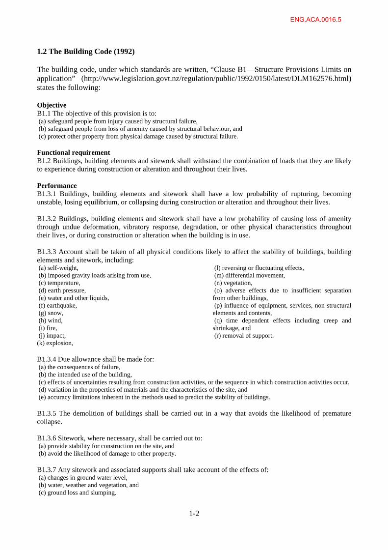
1.2 The Building Code (1992) The building code, under which standards are written, “Clause B1—Structure Provisions Limits on application” (http://www.legislation.govt.nz/regulation/public/1992/0150/latest/DLM162576.html) states the following: Objective B1.1 The objective of this provision is to: (a) safeguard people from injury caused by structural failure, (b) safeguard people from loss of amenity caused by structural behaviour, and (c) protect other property from physical damage caused by structural failure. Functional requirement B1.2 Buildings, building elements and sitework shall withstand the combination of loads that they are likely to experience during construction or alteration and throughout their lives. Performance B1.3.1 Buildings, building elements and sitework shall have a low probability of rupturing, becoming unstable, losing equilibrium, or collapsing during construction or alteration and throughout their lives. B1.3.2 Buildings, building elements and sitework shall have a low probability of causing loss of amenity through undue deformation, vibratory response, degradation, or other physical characteristics throughout their lives, or during construction or alteration when the building is in use. B1.3.3 Account shall be taken of all physical conditions likely to affect the stability of buildings, building elements and sitework, including: (a) self-weight, (b) imposed gravity loads arising from use, (c) temperature, (d) earth pressure, (e) water and other liquids, (f) earthquake, (g) snow, (h) wind, (i) fire, (j) impact, (k) explosion,
(l) reversing or fluctuating effects, (m) differential movement, (n) vegetation, (o) adverse effects due to insufficient separation from other buildings, (p) influence of equipment, services, non-structural elements and contents, (q) time dependent effects including creep and shrinkage, and (r) removal of support.
B1.3.4 Due allowance shall be made for: (a) the consequences of failure, (b) the intended use of the building, (c) effects of uncertainties resulting from construction activities, or the sequence in which construction activities occur, (d) variation in the properties of materials and the characteristics of the site, and (e) accuracy limitations inherent in the methods used to predict the stability of buildings. B1.3.5 The demolition of buildings shall be carried out in a way that avoids the likelihood of premature collapse. B1.3.6 Sitework, where necessary, shall be carried out to: (a) provide stability for construction on the site, and (b) avoid the likelihood of damage to other property. B1.3.7 Any sitework and associated supports shall take account of the effects of: (a) changes in ground water level, (b) water, weather and vegetation, and (c) ground loss and slumping.
ENG.ACA.0016.5
1-2
1.3 Popular Forms of NZ Structural Concrete and Steel Commercial Construction When British and European settlers first arrived in New Zealand, they built structures similar to those in their homeland. This included many unreinforced masonry (URM) brick and stone structures of up to 3 or 4 storeys as well as timber structures using the abundant natural supply. In Britain, earthquakes were very rare, and there was little knowledge about design to mitigate earthquake damage, so design for earthquake was not considered in New Zealand for many years. Popular forms of construction in NZ have been the following:
Unreinforced masonry (URM) buildings were popular until about 1940 Timber framed buildings have continued to be popular. Steel frames from riveted construction were popular from the 1910s until about
1960, but welded and bolted steel moment frames started taking over from the late 1950s. These framing systems were used until the mid-1970’s when significant constructional and industrial relations issues stopped the use of steel in multi-storey commercial and residential construction (MacRae et al. 2010). Steel structures have gradually been regaining popularity from that time mainly with shop-welded-site bolted construction. Eccentrically braced frames have become popular and are now the most commonly used form of seismic-resisting system in multi-storey steel frames as well as being used in a minority of precast concrete framed buildings. In 2009, structural steel is used as the major framing element in over 50% of the buildings nationwide, with percentages varying from centre to centre.
Concrete moment frames with masonry infill were common until about 1970. Non-ductile concrete moment frames were used until about 1980, and thereafter
ductile concrete moment frames have been used. Concrete tilt panel single storey frames were used from about 1950, and multi-
storey tilt panel buildings were also used after 1980. Structures including concrete structural walls have been used since the 1930s. Partially filled and lightly reinforced concrete blocks has been used since the 1950s,
and structures with all blocks filled have been used since the 1980s. Heavy masonry or plaster cladding was used until about 1990. Precast concrete
flooring systems have been used since about 1966. Seismic isolation has been used in some structures since the late 1970s. Other techniques to limit damage have been used since about 2005.
ENG.ACA.0016.6
1-3
1.4 Comparisons with Different Standards In Fenwick and MacRae (2009), “it is shown that simple comparisons of response spectra and limiting inter-storey drifts can give misleading conclusions regarding relative strength and stiffness requirements unless allowance is made for many other interacting factors.” In fact, “to assess how a structure designed in an earlier decade matches up to current design criteria four different aspects need to be considered, namely;
The strength of the structure; The stiffness of the structure; The detailing used in the different structural elements; The hierarchy of failure that will occur to ensure that in the event of a major earthquake a
ductile failure mechanism will form in preference to non-ductile failure modes.” Also, “many different factors in a structural standard contribute to the minimum specified strength and stiffness values. For a realistic comparison to be made between different structural codes/standards over the decades allowance must be made for differences in;
Design spectra; Inter-storey drift limits; Allowances for accidental torsion; Allowances for P-delta actions; Assumptions made regarding section properties and in particular allowance for the influence
of flexural cracking on effective stiffness; Allowance made for inelastic deformation on storey drift; Allowance made for over-estimate of inter-storey deflections in elastic analysis with the
equivalent static method compared with other methods of analysis.” Comparisons in strength and stiffness for concrete structures are described by Fenwick and MacRae (2009).
ENG.ACA.0016.7
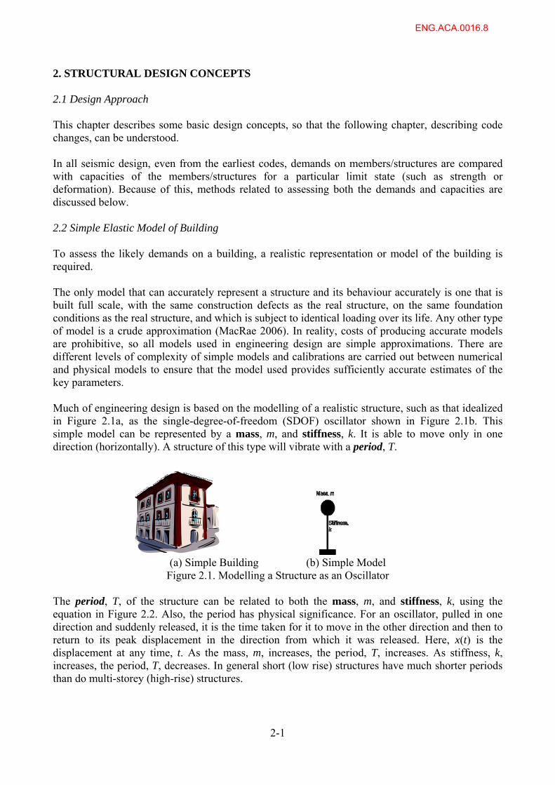
2. STRUCTURAL DESIGN CONCEPTS 2.1 Design Approach This chapter describes some basic design concepts, so that the following chapter, describing code changes, can be understood. In all seismic design, even from the earliest codes, demands on members/structures are compared with capacities of the members/structures for a particular limit state (such as strength or deformation). Because of this, methods related to assessing both the demands and capacities are discussed below. 2.2 Simple Elastic Model of Building To assess the likely demands on a building, a realistic representation or model of the building is required. The only model that can accurately represent a structure and its behaviour accurately is one that is built full scale, with the same construction defects as the real structure, on the same foundation conditions as the real structure, and which is subject to identical loading over its life. Any other type of model is a crude approximation (MacRae 2006). In reality, costs of producing accurate models are prohibitive, so all models used in engineering design are simple approximations. There are different levels of complexity of simple models and calibrations are carried out between numerical and physical models to ensure that the model used provides sufficiently accurate estimates of the key parameters. Much of engineering design is based on the modelling of a realistic structure, such as that idealized in Figure 2.1a, as the single-degree-of-freedom (SDOF) oscillator shown in Figure 2.1b. This simple model can be represented by a mass, m, and stiffness, k. It is able to move only in one direction (horizontally). A structure of this type will vibrate with a period, T.
2-1
(a) Simple Building (b) Simple Model Figure 2.1. Modelling a Structure as an Oscillator
The period, T, of the structure can be related to both the mass, m, and stiffness, k, using the equation in Figure 2.2. Also, the period has physical significance. For an oscillator, pulled in one direction and suddenly released, it is the time taken for it to move in the other direction and then to return to its peak displacement in the direction from which it was released. Here, x(t) is the displacement at any time, t. As the mass, m, increases, the period, T, increases. As stiffness, k, increases, the period, T, decreases. In general short (low rise) structures have much shorter periods than do multi-storey (high-rise) structures.
ENG.ACA.0016.8
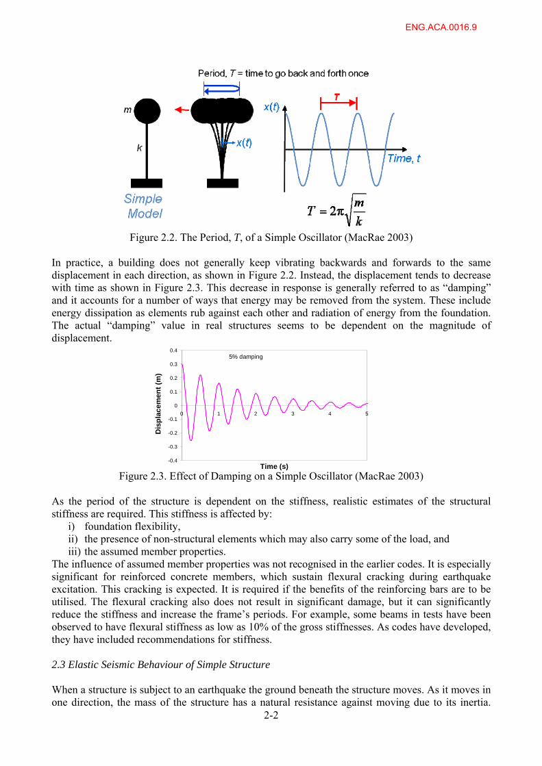
Figure 2.2. The Period, T, of a Simple Oscillator (MacRae 2003)
In practice, a building does not generally keep vibrating backwards and forwards to the same displacement in each direction, as shown in Figure 2.2. Instead, the displacement tends to decrease with time as shown in Figure 2.3. This decrease in response is generally referred to as “damping” and it accounts for a number of ways that energy may be removed from the system. These include energy dissipation as elements rub against each other and radiation of energy from the foundation. The actual “damping” value in real structures seems to be dependent on the magnitude of displacement.
-0.4
-0.3
-0.2
-0.1
0
0.1
0.2
0.3
0.4
0 1 2 3 4 5
Time (s)
Dis
pla
cem
ent
(m)
5% damping
Figure 2.3. Effect of Damping on a Simple Oscillator (MacRae 2003) As the period of the structure is dependent on the stiffness, realistic estimates of the structural stiffness are required. This stiffness is affected by:
i) foundation flexibility, ii) the presence of non-structural elements which may also carry some of the load, and iii) the assumed member properties.
The influence of assumed member properties was not recognised in the earlier codes. It is especially significant for reinforced concrete members, which sustain flexural cracking during earthquake excitation. This cracking is expected. It is required if the benefits of the reinforcing bars are to be utilised. The flexural cracking also does not result in significant damage, but it can significantly reduce the stiffness and increase the frame’s periods. For example, some beams in tests have been observed to have flexural stiffness as low as 10% of the gross stiffnesses. As codes have developed, they have included recommendations for stiffness. 2.3 Elastic Seismic Behaviour of Simple Structure
2-2
When a structure is subject to an earthquake the ground beneath the structure moves. As it moves in one direction, the mass of the structure has a natural resistance against moving due to its inertia.
ENG.ACA.0016.9
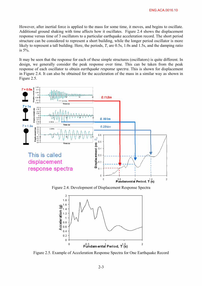
However, after inertial force is applied to the mass for some time, it moves, and begins to oscillate. Additional ground shaking with time affects how it oscillates. Figure 2.4 shows the displacement response versus time of 3 oscillators to a particular earthquake acceleration record. The short period structure can be considered to represent a short building, while the longer period oscillator is more likely to represent a tall building. Here, the periods, T, are 0.5s, 1.0s and 1.5s, and the damping ratio is 5%.
It may be seen that the response for each of these simple structures (oscillators) is quite different. In design, we generally consider the peak response over time. This can be taken from the peak response of each oscillator to obtain earthquake response spectra. This is shown for displacement in Figure 2.4. It can also be obtained for the acceleration of the mass in a similar way as shown in Figure 2.5.
Figure 2.4. Development of Displacement Response Spectra
Figure 2.5. Example of Acceleration Response Spectra for One Earthquake Record
2-3
ENG.ACA.0016.10
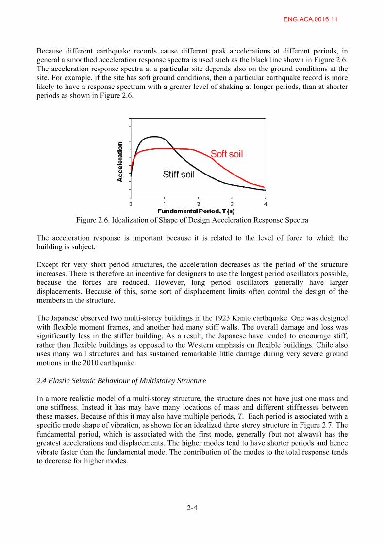
Because different earthquake records cause different peak accelerations at different periods, in general a smoothed acceleration response spectra is used such as the black line shown in Figure 2.6. The acceleration response spectra at a particular site depends also on the ground conditions at the site. For example, if the site has soft ground conditions, then a particular earthquake record is more likely to have a response spectrum with a greater level of shaking at longer periods, than at shorter periods as shown in Figure 2.6.
Figure 2.6. Idealization of Shape of Design Acceleration Response Spectra
The acceleration response is important because it is related to the level of force to which the building is subject. Except for very short period structures, the acceleration decreases as the period of the structure increases. There is therefore an incentive for designers to use the longest period oscillators possible, because the forces are reduced. However, long period oscillators generally have larger displacements. Because of this, some sort of displacement limits often control the design of the members in the structure. The Japanese observed two multi-storey buildings in the 1923 Kanto earthquake. One was designed with flexible moment frames, and another had many stiff walls. The overall damage and loss was significantly less in the stiffer building. As a result, the Japanese have tended to encourage stiff, rather than flexible buildings as opposed to the Western emphasis on flexible buildings. Chile also uses many wall structures and has sustained remarkable little damage during very severe ground motions in the 2010 earthquake. 2.4 Elastic Seismic Behaviour of Multistorey Structure In a more realistic model of a multi-storey structure, the structure does not have just one mass and one stiffness. Instead it has may have many locations of mass and different stiffnesses between these masses. Because of this it may also have multiple periods, T. Each period is associated with a specific mode shape of vibration, as shown for an idealized three storey structure in Figure 2.7. The fundamental period, which is associated with the first mode, generally (but not always) has the greatest accelerations and displacements. The higher modes tend to have shorter periods and hence vibrate faster than the fundamental mode. The contribution of the modes to the total response tends to decrease for higher modes.
2-4
ENG.ACA.0016.11
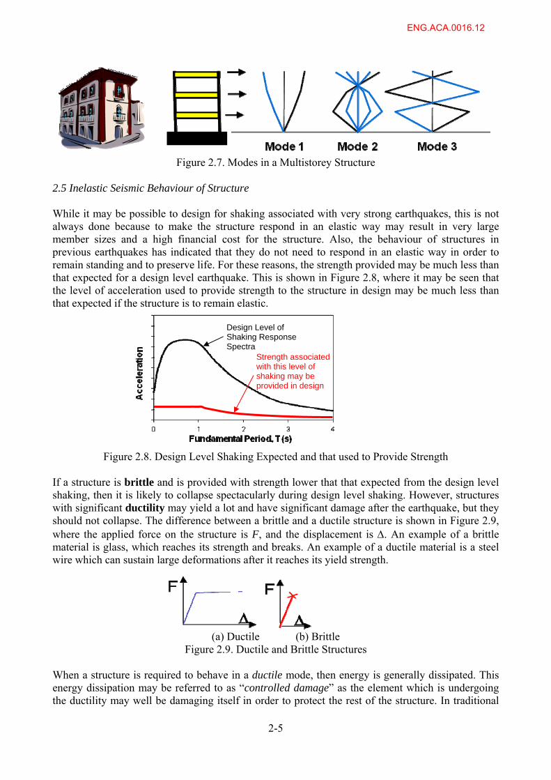
Figure 2.7. Modes in a Multistorey Structure
2.5 Inelastic Seismic Behaviour of Structure While it may be possible to design for shaking associated with very strong earthquakes, this is not always done because to make the structure respond in an elastic way may result in very large member sizes and a high financial cost for the structure. Also, the behaviour of structures in previous earthquakes has indicated that they do not need to respond in an elastic way in order to remain standing and to preserve life. For these reasons, the strength provided may be much less than that expected for a design level earthquake. This is shown in Figure 2.8, where it may be seen that the level of acceleration used to provide strength to the structure in design may be much less than that expected if the structure is to remain elastic.
Design Level of Shaking Response Spectra
Strength associated with this level of shaking may be provided in design
Figure 2.8. Design Level Shaking Expected and that used to Provide Strength If a structure is brittle and is provided with strength lower that that expected from the design level shaking, then it is likely to collapse spectacularly during design level shaking. However, structures with significant ductility may yield a lot and have significant damage after the earthquake, but they should not collapse. The difference between a brittle and a ductile structure is shown in Figure 2.9, where the applied force on the structure is F, and the displacement is . An example of a brittle material is glass, which reaches its strength and breaks. An example of a ductile material is a steel wire which can sustain large deformations after it reaches its yield strength.
(a) Ductile (b) Brittle
Figure 2.9. Ductile and Brittle Structures When a structure is required to behave in a ductile mode, then energy is generally dissipated. This energy dissipation may be referred to as “controlled damage” as the element which is undergoing the ductility may well be damaging itself in order to protect the rest of the structure. In traditional
2-5
ENG.ACA.0016.12
reinforced concrete and steel buildings, yielding of the steel is the method that has been used to provide the ductility and energy dissipation. A building that has experienced significant shaking and has yielded, and used ductility, may have sustained significant damage. It may also not be vertical after the earthquake. As a result it may require major repair or it may need to be demolished. This is consistent with the current philosophy for design of ordinary structures that requires prevention of life loss after a design level earthquake, while damage may be acceptable. The behaviour is similar to that of a car in a crash. In a large crash, the car yields, crumples and sacrifices itself in a controlled way so that it protects the passengers, but the car itself is destroyed and cannot be used again. Providing ductility may be carried out by either:
a) Providing all elements of the frame with ductility, or b) Providing some elements with ductility, and making sure that the brittle ones do not
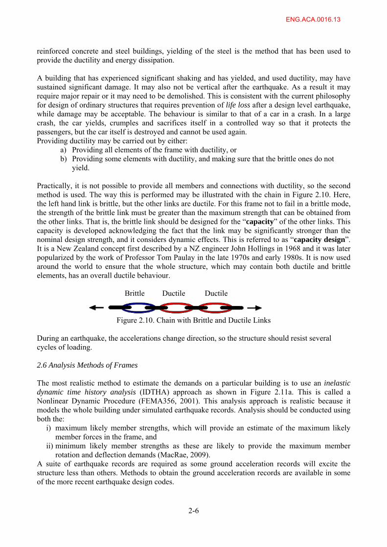
yield. Practically, it is not possible to provide all members and connections with ductility, so the second method is used. The way this is performed may be illustrated with the chain in Figure 2.10. Here, the left hand link is brittle, but the other links are ductile. For this frame not to fail in a brittle mode, the strength of the brittle link must be greater than the maximum strength that can be obtained from the other links. That is, the brittle link should be designed for the “capacity” of the other links. This capacity is developed acknowledging the fact that the link may be significantly stronger than the nominal design strength, and it considers dynamic effects. This is referred to as “capacity design”. It is a New Zealand concept first described by a NZ engineer John Hollings in 1968 and it was later popularized by the work of Professor Tom Paulay in the late 1970s and early 1980s. It is now used around the world to ensure that the whole structure, which may contain both ductile and brittle elements, has an overall ductile behaviour.
Brittle Ductile Ductile
Figure 2.10. Chain with Brittle and Ductile Links During an earthquake, the accelerations change direction, so the structure should resist several cycles of loading. 2.6 Analysis Methods of Frames The most realistic method to estimate the demands on a particular building is to use an inelastic dynamic time history analysis (IDTHA) approach as shown in Figure 2.11a. This is called a Nonlinear Dynamic Procedure (FEMA356, 2001). This analysis approach is realistic because it models the whole building under simulated earthquake records. Analysis should be conducted using both the:
i) maximum likely member strengths, which will provide an estimate of the maximum likely member forces in the frame, and
ii) minimum likely member strengths as these are likely to provide the maximum member rotation and deflection demands (MacRae, 2009).
A suite of earthquake records are required as some ground acceleration records will excite the structure less than others. Methods to obtain the ground acceleration records are available in some of the more recent earthquake design codes.
2-6
ENG.ACA.0016.13
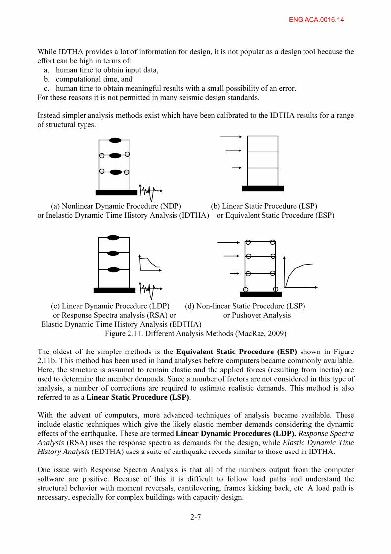
While IDTHA provides a lot of information for design, it is not popular as a design tool because the effort can be high in terms of:
a. human time to obtain input data, b. computational time, and c. human time to obtain meaningful results with a small possibility of an error.
For these reasons it is not permitted in many seismic design standards.
Instead simpler analysis methods exist which have been calibrated to the IDTHA results for a range of structural types.
2-7
(a) Nonlinear Dynamic Procedure (NDP) (b) Linear Static Procedure (LSP) or Inelastic Dynamic Time History Analysis (IDTHA) or Equivalent Static Procedure (ESP) (c) Linear Dynamic Procedure (LDP) (d) Non-linear Static Procedure (LSP) or Response Spectra analysis (RSA) or or Pushover Analysis Elastic Dynamic Time History Analysis (EDTHA)
Figure 2.11. Different Analysis Methods (MacRae, 2009) The oldest of the simpler methods is the Equivalent Static Procedure (ESP) shown in Figure 2.11b. This method has been used in hand analyses before computers became commonly available. Here, the structure is assumed to remain elastic and the applied forces (resulting from inertia) are used to determine the member demands. Since a number of factors are not considered in this type of analysis, a number of corrections are required to estimate realistic demands. This method is also referred to as a Linear Static Procedure (LSP). With the advent of computers, more advanced techniques of analysis became available. These include elastic techniques which give the likely elastic member demands considering the dynamic effects of the earthquake. These are termed Linear Dynamic Procedures (LDP). Response Spectra Analysis (RSA) uses the response spectra as demands for the design, while Elastic Dynamic Time History Analysis (EDTHA) uses a suite of earthquake records similar to those used in IDTHA. One issue with Response Spectra Analysis is that all of the numbers output from the computer software are positive. Because of this it is difficult to follow load paths and understand the structural behavior with moment reversals, cantilevering, frames kicking back, etc. A load path is necessary, especially for complex buildings with capacity design.
ENG.ACA.0016.14
Over recent years, people have become interested in nonlinear static procedures (NSP) such as pushover analysis. These show some of the non-linear aspects of structural behaviour, but they still have a number of limitations (Hoedajanto and MacRae, 2003). These include:
i) A lateral force distribution (or distributions) and a target displacement need to be selected ii) Member forces may be underestimated iii) Dynamic magnifications are not found.
Other techniques for design also exist, such as nonlinear cyclic procedures (MacRae, 2004) but these are not commonly used in design of buildings. All analysis techniques are limited by the type of model to which they are applied, and the assumptions regarding frame performance. This is particularly significant in buildings which undergo some type of gapping, or uplift. 2.7 Modifications Required for Simple Methods of Analysis Because the analysis methods used in current code design are generally based on elastic analysis methods, such as the ESP (a LSP) and the LDP methods, various modifications need to be made to them in order that they provide a realistic estimate of the demands. a. Analysis methods and their limitations (Damping values)
0
0.1
0.2
0.3
0.4
0.5
0.6
0.7
0.8
0.9
1
0 1 2 3Fundamental Period, T (s)
Dis
pla
cem
en
t (m
)
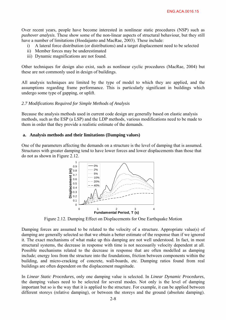
One of the parameters affecting the demands on a structure is the level of damping that is assumed. Structures with greater damping tend to have lower forces and lower displacements than those that do not as shown in Figure 2.12.
4
0%
2%
5%
10%
20%
40%
Figure 2.12. Damping Effect on Displacements for One Earthquake Motion Damping forces are assumed to be related to the velocity of a structure. Appropriate value(s) of damping are generally selected so that we obtain a better estimate of the response than if we ignored it. The exact mechanisms of what make up this damping are not well understood. In fact, in most structural systems, the decrease in response with time is not necessarily velocity dependent at all. Possible mechanisms related to the decrease in response that are often modelled as damping include; energy loss from the structure into the foundations, friction between components within the building, and micro-cracking of concrete, wall-boards, etc. Damping ratios found from real buildings are often dependent on the displacement magnitude. In Linear Static Procedures, only one damping value is selected. In Linear Dynamic Procedures, the damping values need to be selected for several modes. Not only is the level of damping important but so is the way that it is applied to the structure. For example, it can be applied between different storeys (relative damping), or between the storeys and the ground (absolute damping).
2-8
ENG.ACA.0016.15
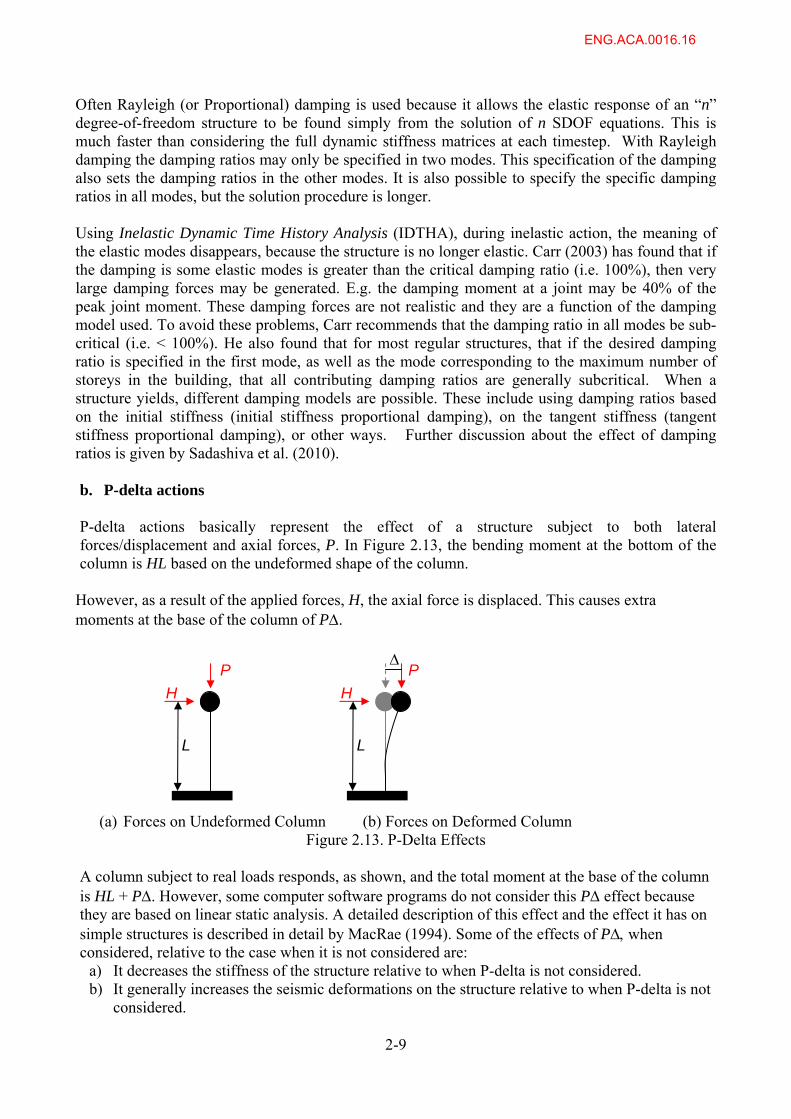
Often Rayleigh (or Proportional) damping is used because it allows the elastic response of an “n” degree-of-freedom structure to be found simply from the solution of n SDOF equations. This is much faster than considering the full dynamic stiffness matrices at each timestep. With Rayleigh damping the damping ratios may only be specified in two modes. This specification of the damping also sets the damping ratios in the other modes. It is also possible to specify the specific damping ratios in all modes, but the solution procedure is longer. Using Inelastic Dynamic Time History Analysis (IDTHA), during inelastic action, the meaning of the elastic modes disappears, because the structure is no longer elastic. Carr (2003) has found that if the damping is some elastic modes is greater than the critical damping ratio (i.e. 100%), then very large damping forces may be generated. E.g. the damping moment at a joint may be 40% of the peak joint moment. These damping forces are not realistic and they are a function of the damping model used. To avoid these problems, Carr recommends that the damping ratio in all modes be sub-critical (i.e. < 100%). He also found that for most regular structures, that if the desired damping ratio is specified in the first mode, as well as the mode corresponding to the maximum number of storeys in the building, that all contributing damping ratios are generally subcritical. When a structure yields, different damping models are possible. These include using damping ratios based on the initial stiffness (initial stiffness proportional damping), on the tangent stiffness (tangent stiffness proportional damping), or other ways. Further discussion about the effect of damping ratios is given by Sadashiva et al. (2010). b. P-delta actions P-delta actions basically represent the effect of a structure subject to both lateral forces/displacement and axial forces, P. In Figure 2.13, the bending moment at the bottom of the column is HL based on the undeformed shape of the column.
However, as a result of the applied forces, H, the axial force is displaced. This causes extra moments at the base of the column of P.
H
L
P
H
L
P
(a) Forces on Undeformed Column (b) Forces on Deformed Column
Figure 2.13. P-Delta Effects A column subject to real loads responds, as shown, and the total moment at the base of the column is HL + P. However, some computer software programs do not consider this P effect because they are based on linear static analysis. A detailed description of this effect and the effect it has on simple structures is described in detail by MacRae (1994). Some of the effects of P when considered, relative to the case when it is not considered are:
a) It decreases the stiffness of the structure relative to when P-delta is not considered. b) It generally increases the seismic deformations on the structure relative to when P-delta is not
considered.
2-9
ENG.ACA.0016.16
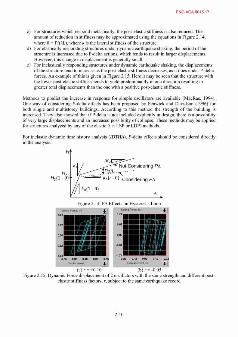
c) For structures which respond inelastically, the post-elastic stiffness is also reduced. The amount of reduction in stiffness may be approximated using the equations in Figure 2.14, where = P/(kL), where k is the lateral stiffness of the structure.
d) For elastically responding structures under dynamic earthquake shaking, the period of the structure is increased due to P-delta actions, which tends to result in larger displacements. However, this change in displacement is generally small.
e) For inelastically responding structures under dynamic earthquake shaking, the displacements of the structure tend to increase as the post-elastic stiffness decreases, as it does under P-delta forces. An example of this is given in Figure 2.15. Here it may be seen that the structure with the lower post-elastic stiffness tends to yield predominantly in one direction resulting in greater total displacements than the one with a positive post-elastic stiffness.
Methods to predict the increase in response for simple oscillators are available (MacRae, 1994). One way of considering P-delta effects has been proposed by Fenwick and Davidson (1996) for both single and multistorey buildings. According to this method the strength of the building is increased. They also showed that if P-delta is not included explicitly in design, there is a possibility of very large displacements and an increased possibility of collapse. These methods may be applied for structures analyzed by any of the elastic (i.e. LSP or LDP) methods. For inelastic dynamic time history analysis (IDTHA), P-delta effects should be considered directly in the analysis.
Considering P
Not Considering P
ko(1 - )
Hy PL
ko(r - )
rko ko
Hy(1 - )
H
Figure 2.14. P Effects on Hysteresis Loop
(a) r = +0.10 (b) r = -0.05
Figure 2.15. Dynamic Force displacement of 2 oscillators with the same strength and different post-elastic stiffness factors, r, subject to the same earthquake record
2-10
ENG.ACA.0016.17
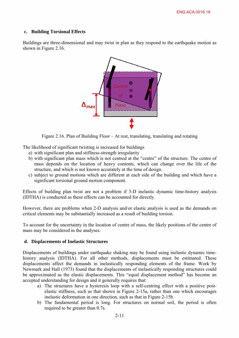
c. Building Torsional Effects Buildings are three-dimensional and may twist in plan as they respond to the earthquake motion as shown in Figure 2.16.
Figure 2.16. Plan of Building Floor – At rest, translating, translating and rotating
The likelihood of significant twisting is increased for buildings
a) with significant plan and stiffness-strength irregularity b) with significant plan mass which is not centred at the “centre” of the structure. The centre of
mass depends on the location of heavy contents, which can change over the life of the structure, and which is not known accurately at the time of design.
c) subject to ground motions which are different at each side of the building and which have a significant torsional ground motion component.
Effects of building plan twist are not a problem if 3-D inelastic dynamic time-history analysis (IDTHA) is conducted as these effects can be accounted for directly. However, there are problems when 2-D analysis and/or elastic analysis is used as the demands on critical elements may be substantially increased as a result of building torsion. To account for the uncertainty in the location of centre of mass, the likely positions of the centre of mass may be considered in the analyses. d. Displacements of Inelastic Structures
Displacements of buildings under earthquake shaking may be found using inelastic dynamic time-history analysis (IDTHA). For all other methods, displacements must be estimated. These displacements affect the demands in inelastically responding elements of the frame. Work by Newmark and Hall (1973) found that the displacements of inelastically responding structures could be approximated as the elastic displacements. This “equal displacement method” has become an accepted understanding for design and it generally requires that:
a) The structures have a hysteresis loop with a self-centring effect with a positive post-elastic stiffness, such as that shown in Figure 2-15a, rather than one which encourages inelastic deformation in one direction, such as that in Figure 2-15b.
b) The fundamental period is long. For structures on normal soil, the period is often required to be greater than 0.7s.
2-11
ENG.ACA.0016.18
c) The structure is not in the region of fault rupture positive directivity. Positive directivity effects occur when the fault rupture propagates in the direction toward the site considered, and it can result in more severe elastic and inelastic demands than if the rupture occurs in another direction (MacRae et al. 2004).
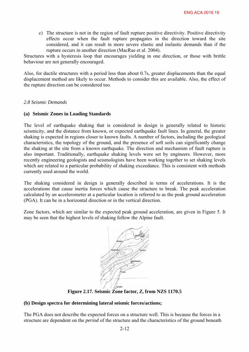
Structures with a hysteresis loop that encourages yielding in one direction, or those with brittle behaviour are not generally encouraged. Also, for ductile structures with a period less than about 0.7s, greater displacements than the equal displacement method are likely to occur. Methods to consider this are available. Also, the effect of the rupture direction can be considered too. 2.8 Seismic Demands (a) Seismic Zones in Loading Standards The level of earthquake shaking that is considered in design is generally related to historic seismicity, and the distance from known, or expected earthquake fault lines. In general, the greater shaking is expected in regions closer to known faults. A number of factors, including the geological characteristics, the topology of the ground, and the presence of soft soils can significantly change the shaking at the site from a known earthquake. The direction and mechanism of fault rupture is also important. Traditionally, earthquake shaking levels were set by engineers. However, more recently engineering geologists and seismologists have been working together to set shaking levels which are related to a particular probability of shaking exceedance. This is consistent with methods currently used around the world. The shaking considered in design is generally described in terms of accelerations. It is the accelerations that cause inertia forces which cause the structure to break. The peak acceleration calculated by an accelerometer at a particular location is referred to as the peak ground acceleration (PGA). It can be in a horizontal direction or in the vertical direction. Zone factors, which are similar to the expected peak ground acceleration, are given in Figure 5. It may be seen that the highest levels of shaking follow the Alpine fault.
Figure 2.17. Seismic Zone factor, Z, from NZS 1170.5
(b) Design spectra for determining lateral seismic forces/actions; The PGA does not describe the expected forces on a structure well. This is because the forces in a structure are dependent on the period of the structure and the characteristics of the ground beneath
2-12
ENG.ACA.0016.19
2-13
the structure. The black line in Figure 6 shows the response spectra shape for a particular level of shaking. While the response spectra for individual records are sensitive to period, the design spectra are generally smoothed. From the shape of the idealized spectra, it may be seen that earthquakes tend to cause greater accelerations to shorter buildings than to very tall structures which have a longer period. As an alternative to response spectra, design checks may be made using a suite of ground motion acceleration records obtained for the site considered. Engineering seismologists are able to generate such records. It should be noted that the size and shape of spectra also depend on the magnitude of shaking considered. Less frequent shaking will have a greater magnitude of shaking than more frequent shaking. 2.9 Building Design Philosophy The general design philosophy for design has been expressed by Paulay in the 1980s. That is:
i) Structures should be provided with stiffness so that they do not have any non-structural damage (e.g. cracking of gypsum board walls) in small levels of earthquake shaking.
ii) Structures should be provided with strength so that they do not have any structural damage (e.g. yielding in the structural frames) in moderate levels of earthquake shaking.
iii) Structures should be provided with sufficient ductility so that they preserve life and do not collapse in high levels of earthquake shaking.
In the discussion below, we will concentrate only on the collapse prevention of structures for which ductility is often relied upon to reduce the resistance. More specifically, to prevent collapse in design level earthquake shaking:
a. Sufficient stiffness and strength must be provided to a building so that even if it does behave in a ductile mode, it is not likely to collapse. This strength also protects the structure against damage in smaller levels of earthquake. Codes may require that strength is sufficient to resist very little of the total earthquake shaking. The design level of shaking used to determine the strength of the structure may be as low as one-sixth (16%) of that that expected for a design level earthquake as shown in Figure 2.18.
b. Sufficient ductility must be provided to lateral force resisting frame elements to undergo the expected displacements.
c. Brittle elements of the lateral force resisting frame, or elements not designed to undergo inelastic deformation, must be provided with sufficient strength to ensure that their strength is not reached. This is commonly referred to as “capacity design”, because these brittle elements are generally designed based on the “capacity” of the ductile elements.
d. Other elements of the building, such as the gravity loaded frames, must be designed to cope with the displacements of the lateral force resisting frame without collapsing.
As previously noted, these minimum code requirements are to preserve life and to prevent collapse rather than to ensure further use of the building. It is possible that even if the structure remains standing, that there may be a large amount of damage and the structure may be on a lean and require demolition after the earthquake. Design according to current codes is to ensure “life-safety” rather than to protect the building for further use. It should be emphasized that building codes specify the minimum level of earthquake that a structure may be designed for. Other factors may mean that the frame member sizes are significantly greater than that specified in the codes and this can result in the frame having a greater
ENG.ACA.0016.20
2-14
earthquake resistance than that in specified codes (if appropriate detailing is followed). The greater earthquake resistance than the code minimum level may be due to factors such as:
i) frame lateral stiffness requirements governing member sizes, ii) other environmental loads, such as that from wind governing the sizes, or iii) building owners specifically requiring that the building be designed for a greater level of
earthquake resistance in order to provide greater protection both to the occupants and to the structure.
In general, important structures, such as hospitals, communications centres, and those providing occupation for many people, are designed for a greater level of earthquake shaking than ordinary commercial structures. 2.10 Method of Considering Structural Safety In a satisfactory design it is required that the demand on the structure, or part of the structure considered, does not exceed the capacity for the specific limit state (e.g. fracture or yield) being considered under the specific loading. Traditionally, for all types of design an approach based on keeping the demand below some permissible capacity is used. This is called Allowable Stress Design (ASD) in the steel codes (or Working Stress Design) approach in the concrete codes. Here, the calculated stress in a member is limited to a proportion of the stress capacity, which may be the yield stress of steel or crushing stress of concrete. The factor of safety is largely a proportion of the stress capacity to the allowable stress. Because linear analysis is generally used, the ASD/WSD approach can be also be written in terms of nominal applied force demand, Q, and the nominal resistance, Rn, applied force according to Equation 1 below. That is, the nominal Demand, Q, must be less than the nominal Capacity, Rn, divided by a safety factor, SF. The safety factor, SF, has a value which is greater than unity. Often, a value of 1.66 is used. Q < Rn (1) SF More recent codes have tended to use a different approach to consider the factor of safety. This is called many things such as Limit State Design (LSD) in the steel codes, Ultimate Strength Design (USD) by the concrete codes, or Load and Resistance Factor Design (LRFD) by some overseas codes. In this approach, the safety factor is split into two components – a load factor to recognize the probable variation in loads, , and a resistance factor to represent the probable variation in resistance, . It has been argued that the USD or LSD method is much more logical than the older WSD (or USD) method. These factors and may be calibrated to provide a factor of safety similar to SF, but the total factors of safety between the two methods do vary slightly in practice. The symbol is a summation sign which allows the effect of different demands, Q, to be combined with different load factors, , to be summed together.
∑ Q < Rn (2) The reason that this discussion between these newer and older methods is important is that it affects the design of structures. For example, the USD standard design flexural strength corresponds approximately to 1.3 times the working stress moment in RC members (Fenwick and MacRae, 2010).
ENG.ACA.0016.21
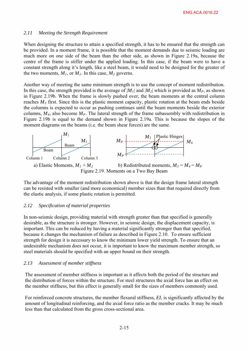
2.11 Meeting the Strength Requirement When designing the structure to attain a specified strength, it has to be ensured that the strength can be provided. In a moment frame, it is possible that the moment demands due to seismic loading are much more on one side of the beam than the other side, as shown in Figure 2.19a, because the centre of the frame is stiffer under the applied loading. In this case, if the beam were to have a constant strength along it’s length, like a steel beam, it would need to be designed for the greater of the two moments, M1, or M2. In this case, M2 governs. Another way of meeting the same minimum strength is to use the concept of moment redistribution. In this case, the strength provided is the average of |M1| and |M2| which is provided as MP, as shown in Figure 2.19b. When the frame is slowly pushed over, the beam moments at the central column reaches M3 first. Since this is the plastic moment capacity, plastic rotation at the beam ends beside the columns is expected to occur as pushing continues until the beam moments beside the exterior columns, M4, also become MP. The lateral strength of the frame subassembly with redistribution in Figure 2.19b is equal to the demand shown in Figure 2.19a. This is because the slopes of the moment diagrams on the beams (i.e. the beam shear forces) are the same.
2-15
M1 M3 Plastic Hinges MP M2 M4
Beam Beam MP
Column 1 Column 2 Column 3 a) Elastic Moments, M1 > M2 b) Redistributed moments, M3 = M4 = MP
Figure 2.19. Moments on a Two Bay Beam The advantage of the moment redistribution shown above is that the design frame lateral strength can be resisted with smaller (and more economical) member sizes than that required directly from the elastic analysis, if some plastic rotation is permitted. 2.12 Specification of material properties
In non-seismic design, providing material with strength greater than that specified is generally desirable, as the structure is stronger. However, in seismic design, the displacement capacity, is important. This can be reduced by having a material significantly stronger than that specified, because it changes the mechanism of failure as described in Figure 2.10. To ensure sufficient strength for design it is necessary to know the minimum lower yield strength. To ensure that an undesirable mechanism does not occur, it is important to know the maximum member strength, so steel materials should be specified with an upper bound on their strength. 2.13 Assessment of member stiffness The assessment of member stiffness is important as it affects both the period of the structure and the distribution of forces within the structure. For steel structures the axial force has an effect on the member stiffness, but this effect is generally small for the sizes of members commonly used. For reinforced concrete structures, the member flexural stiffness, EI, is significantly affected by the amount of longitudinal reinforcing, and the axial force ratio as the member cracks. It may be much less than that calculated from the gross cross-sectional area.
ENG.ACA.0016.22
2.14 Representation of Structural Components in Tests
The idea of a testing a part of a structure should represent the likely behaviour of that part of the structure in an earthquake. The ability to represent this behaviour well depends on:
a) Boundary conditions b) Element representation c) Loading representation
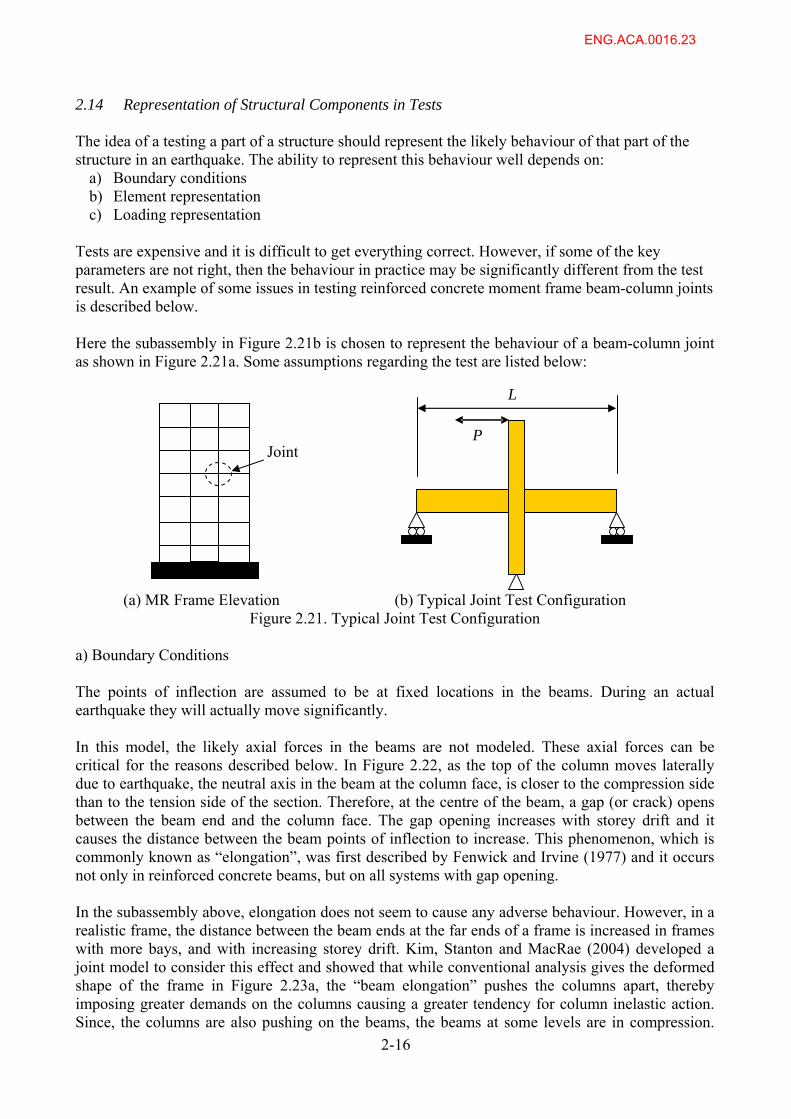
Tests are expensive and it is difficult to get everything correct. However, if some of the key parameters are not right, then the behaviour in practice may be significantly different from the test result. An example of some issues in testing reinforced concrete moment frame beam-column joints is described below. Here the subassembly in Figure 2.21b is chosen to represent the behaviour of a beam-column joint as shown in Figure 2.21a. Some assumptions regarding the test are listed below:
2-16
(a) MR Frame Elevation (b) Typical Joint Test Configuration
L
P
Joint
Figure 2.21. Typical Joint Test Configuration
a) Boundary Conditions The points of inflection are assumed to be at fixed locations in the beams. During an actual earthquake they will actually move significantly. In this model, the likely axial forces in the beams are not modeled. These axial forces can be critical for the reasons described below. In Figure 2.22, as the top of the column moves laterally due to earthquake, the neutral axis in the beam at the column face, is closer to the compression side than to the tension side of the section. Therefore, at the centre of the beam, a gap (or crack) opens between the beam end and the column face. The gap opening increases with storey drift and it causes the distance between the beam points of inflection to increase. This phenomenon, which is commonly known as “elongation”, was first described by Fenwick and Irvine (1977) and it occurs not only in reinforced concrete beams, but on all systems with gap opening. In the subassembly above, elongation does not seem to cause any adverse behaviour. However, in a realistic frame, the distance between the beam ends at the far ends of a frame is increased in frames with more bays, and with increasing storey drift. Kim, Stanton and MacRae (2004) developed a joint model to consider this effect and showed that while conventional analysis gives the deformed shape of the frame in Figure 2.23a, the “beam elongation” pushes the columns apart, thereby imposing greater demands on the columns causing a greater tendency for column inelastic action. Since, the columns are also pushing on the beams, the beams at some levels are in compression.
ENG.ACA.0016.23
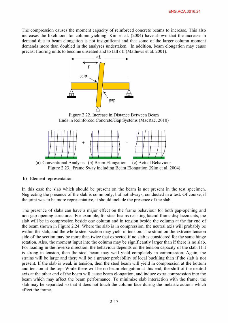
The compression causes the moment capacity of reinforced concrete beams to increase. This also increases the likelihood for column yielding. Kim et al. (2004) have shown that the increase in demand due to beam elongation is not insignificant and that some of the larger column moment demands more than doubled in the analyses undertaken. In addition, beam elongation may cause precast flooring units to become unseated and to fall off (Mathews et al. 2001).
2-17
Figure 2.22. Increase in Distance Between Beam
>L
P
gap
gap
Ends in Reinforced Concrete/Gap Systems (MacRae, 2010)
(a) Conventional Analysis (b) Beam Elongation (c) Actual Behaviour Figure 2.23. Frame Sway including Beam Elongation (Kim et al. 2004)
b) Element representation
In this case the slab which should be present on the beam is not present in the test specimen. Neglecting the presence of the slab is commonly, but not always, conducted in a test. Of course, if the joint was to be more representative, it should include the presence of the slab. The presence of slabs can have a major effect on the frame behaviour for both gap-opening and non-gap-opening structures. For example, for steel beams resisting lateral frame displacements, the slab will be in compression beside one column and in tension beside the column at the far end of the beam shown in Figure 2.24. Where the slab is in compression, the neutral axis will probably be within the slab, and the whole steel section may yield in tension. The strain on the extreme tension side of the section may be more than twice that expected if no slab is considered for the same hinge rotation. Also, the moment input into the column may be significantly larger than if there is no slab. For loading in the reverse direction, the behaviour depends on the tension capacity of the slab. If it is strong in tension, then the steel beam may well yield completely in compression. Again, the strains will be large and there will be a greater probability of local buckling than if the slab is not present. If the slab is weak in tension, then the steel beam will yield in compression at the bottom and tension at the top. While there will be no beam elongation at this end, the shift of the neutral axis at the other end of the beam will cause beam elongation, and induce extra compression into the beam which may affect the beam performance. To minimize slab interaction with the frame, the slab may be separated so that it does not touch the column face during the inelastic actions which affect the frame.
ENG.ACA.0016.24
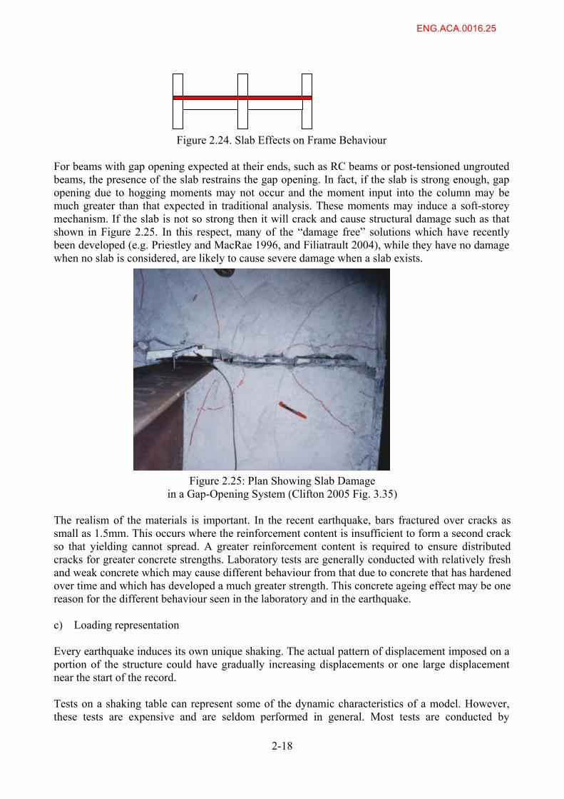
Figure 2.24. Slab Effects on Frame Behaviour For beams with gap opening expected at their ends, such as RC beams or post-tensioned ungrouted beams, the presence of the slab restrains the gap opening. In fact, if the slab is strong enough, gap opening due to hogging moments may not occur and the moment input into the column may be much greater than that expected in traditional analysis. These moments may induce a soft-storey mechanism. If the slab is not so strong then it will crack and cause structural damage such as that shown in Figure 2.25. In this respect, many of the “damage free” solutions which have recently been developed (e.g. Priestley and MacRae 1996, and Filiatrault 2004), while they have no damage when no slab is considered, are likely to cause severe damage when a slab exists.
Figure 2.25: Plan Showing Slab Damage in a Gap-Opening System (Clifton 2005 Fig. 3.35)
The realism of the materials is important. In the recent earthquake, bars fractured over cracks as small as 1.5mm. This occurs where the reinforcement content is insufficient to form a second crack so that yielding cannot spread. A greater reinforcement content is required to ensure distributed cracks for greater concrete strengths. Laboratory tests are generally conducted with relatively fresh and weak concrete which may cause different behaviour from that due to concrete that has hardened over time and which has developed a much greater strength. This concrete ageing effect may be one reason for the different behaviour seen in the laboratory and in the earthquake. c) Loading representation Every earthquake induces its own unique shaking. The actual pattern of displacement imposed on a portion of the structure could have gradually increasing displacements or one large displacement near the start of the record. Tests on a shaking table can represent some of the dynamic characteristics of a model. However, these tests are expensive and are seldom performed in general. Most tests are conducted by
2-18
ENG.ACA.0016.25
2-19
subjecting the subassembly slowly to a lateral loading regime with cycles of increasing displacement in order to get as much information as possible from tests. In some cases, a different loading regime, in which the displacement is applied initially to the maximum value can cause a different failure mode, as the test unit is not progressively weakened (Ranf et al. 2004). Also, earthquake loading is dynamic, and this can cause a different response than found by slowly using a lateral loading regime with cycles of increasing displacement. 2.15 Structural Performance, SP, factor Some standards contain a structural performance, Sp, factor. A number of diverse reasons have been specified for the existence of this factor, which is less than one. Its use reduces both the design forces and displacements on the structure relative to those expected based on considering the structural properties alone together with the level of earthquake excitation. Further discussion about this factor is given in Chapter 4. 2.16 Influence of displacements on stair demands, floor demands and pounding
The behaviour of stairs and floors is being described in another report to the Royal Commission. In this section it is shown how displacements are important in a few cases:
a) In newer buildings, stairs are connected to one level of the structure and allowed to slide on the other level. This means that during an earthquake, the stairs should not carry force so they should not be damaged. This is desirable. However, it is essential that the stairs be provided with sufficient seating so that they do not become unseated during earthquake shaking. Since stairs are a very important part of the building providing entrance and egress, they should possibly be designed to accommodate displacements significantly larger than those expected in the design level earthquake. In order to ensure this, methods to estimate the likely displacements should be robust.
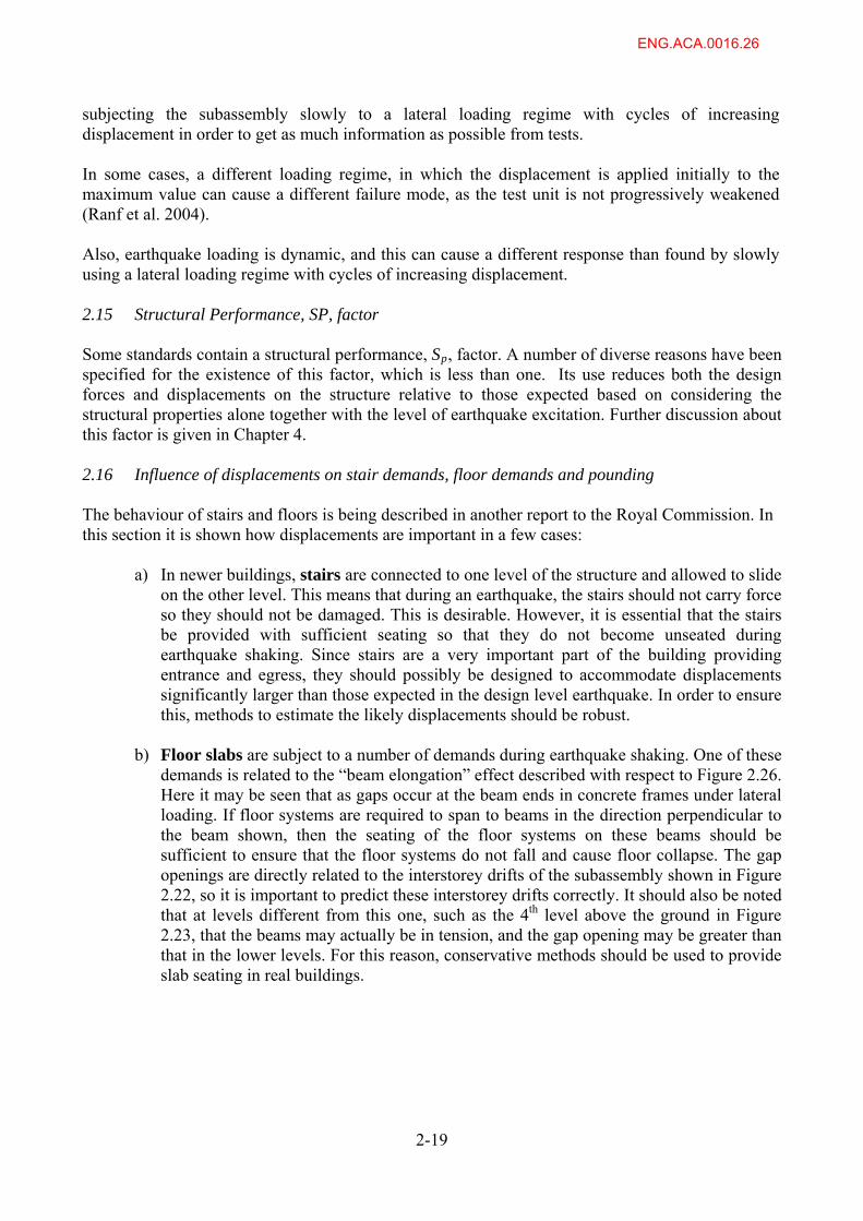
b) Floor slabs are subject to a number of demands during earthquake shaking. One of these demands is related to the “beam elongation” effect described with respect to Figure 2.26. Here it may be seen that as gaps occur at the beam ends in concrete frames under lateral loading. If floor systems are required to span to beams in the direction perpendicular to the beam shown, then the seating of the floor systems on these beams should be sufficient to ensure that the floor systems do not fall and cause floor collapse. The gap openings are directly related to the interstorey drifts of the subassembly shown in Figure 2.22, so it is important to predict these interstorey drifts correctly. It should also be noted that at levels different from this one, such as the 4th level above the ground in Figure 2.23, that the beams may actually be in tension, and the gap opening may be greater than that in the lower levels. For this reason, conservative methods should be used to provide slab seating in real buildings.
ENG.ACA.0016.26
`
2-20
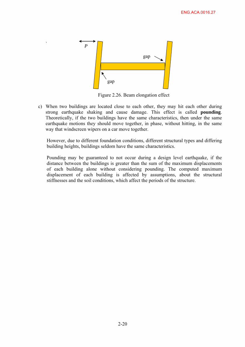
Figure 2.26. Beam elongation effect
c) When two buildings are located close to each other, they may hit each other during strong earthquake shaking and cause damage. This effect is called pounding. Theoretically, if the two buildings have the same characteristics, then under the same earthquake motions they should move together, in phase, without hitting, in the same way that windscreen wipers on a car move together. However, due to different foundation conditions, different structural types and differing building heights, buildings seldom have the same characteristics. Pounding may be guaranteed to not occur during a design level earthquake, if the distance between the buildings is greater than the sum of the maximum displacements of each building alone without considering pounding. The computed maximum displacement of each building is affected by assumptions, about the structural stiffnesses and the soil conditions, which affect the periods of the structure.
P
gap
gap
ENG.ACA.0016.27

3.0 CHANGES IN STANDARDS 3.1. STANDARDS USED AT THE SAME TIME Fenwick and MacRae (2009) described major changes in design Standards by considering pairs of Loadings and Concrete Standards. This has been extended to describe the changes with Steel Standards too in the Table 3.1.
TABLE 3.1. GROUPS OF STANDARDS USED AT SIMILAR TIMES Group Loadings Standard Concrete Standard Steel Standard
A NZS 1170.5; 2004 NZS 3101:2006 NZS3404:1997 + Amdts 1 & 2 (2007)
B NZS 4203; 1992 NZS 3101: 1995 NZS3404:1997
C NZS 4203: 1984 NZS 3101: 1982 NZS 3404:1989
AS 1250: 1981
D NZS 4203: 1976
MOW Code of Practice: 1968
ACI 318: 1971 or provisional NZ Concrete Structures Standard;
MOW Code of Practice: 1968
NZS 3404:1976
E NZSS 1900, Basic Design Loads Chapter 8 (1965)
Design and Construction, Concrete, Chapter 9.3, 1964 (No seismic provisions)
No seismic provisions
F NZSS 95, Pt. IV, Basic loads to be used and methods of application (1955)
UK concrete code of practice, CP114: 1957 (No seismic provisions) and NZSS 95, Pt. V (1939)
No seismic provisions
G 1935 Model Bylaws No seismic provisions
No seismic provisions
Changes to Standards over time are listed in the following sections. Much of the information listed, especially related to the design actions/loadings and concrete Standards, draws heavily on Fenwick and MacRae (2009). This document provides comparative information about:
a) the likely change in computed periods resulting from the changes in computed section properties,
b) the different building fundamental periods for some of the different standard groups, and
c) comparative strengths, stiffnesses and ductility factors of buildings with different periods.
It is shown that the assumptions made can have a significant effect on the demands. Also, a paper is cited in which minimum required strength and stiffness values required by NZS 4203: 1992 and NZS 3101: 1995 were compared with a number of major overseas Standards. This comparison indicated that the New Zealand codes in general required lower strength and stiffness levels for ductile moment resisting frame structures than the overseas codes of practice. Table 5 indicates that little has changed in terms of required strength with the introduction of NZS 1170.5: 2004 but there has been an appreciable decrease in required stiffness in the medium to high seismic zones.
ENG.ACA.0016.28
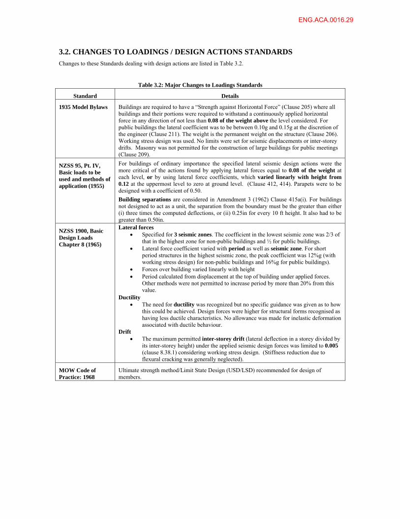
3.2. CHANGES TO LOADINGS / DESIGN ACTIONS STANDARDS
Changes to these Standards dealing with design actions are listed in Table 3.2.
Table 3.2: Major Changes to Loadings Standards
Standard Details
1935 Model Bylaws Buildings are required to have a “Strength against Horizontal Force” (Clause 205) where all buildings and their portions were required to withstand a continuously applied horizontal force in any direction of not less than 0.08 of the weight above the level considered. For public buildings the lateral coefficient was to be between 0.10g and 0.15g at the discretion of the engineer (Clause 211). The weight is the permanent weight on the structure (Clause 206). Working stress design was used. No limits were set for seismic displacements or inter-storey drifts. Masonry was not permitted for the construction of large buildings for public meetings (Clause 209).
NZSS 95, Pt. IV, Basic loads to be used and methods of application (1955)
For buildings of ordinary importance the specified lateral seismic design actions were the more critical of the actions found by applying lateral forces equal to 0.08 of the weight at each level, or by using lateral force coefficients, which varied linearly with height from 0.12 at the uppermost level to zero at ground level. (Clause 412, 414). Parapets were to be designed with a coefficient of 0.50.
Building separations are considered in Amendment 3 (1962) Clause 415a(i). For buildings not designed to act as a unit, the separation from the boundary must be the greater than either (i) three times the computed deflections, or (ii) 0.25in for every 10 ft height. It also had to be greater than 0.50in.
NZSS 1900, Basic Design Loads Chapter 8 (1965)
Lateral forces Specified for 3 seismic zones. The coefficient in the lowest seismic zone was 2/3 of
that in the highest zone for non-public buildings and ½ for public buildings. Lateral force coefficient varied with period as well as seismic zone. For short
period structures in the highest seismic zone, the peak coefficient was 12%g (with working stress design) for non-public buildings and 16%g for public buildings).
Forces over building varied linearly with height Period calculated from displacement at the top of building under applied forces.
Other methods were not permitted to increase period by more than 20% from this value.
Ductility The need for ductility was recognized but no specific guidance was given as to how
this could be achieved. Design forces were higher for structural forms recognised as having less ductile characteristics. No allowance was made for inelastic deformation associated with ductile behaviour.
Drift The maximum permitted inter-storey drift (lateral deflection in a storey divided by
its inter-storey height) under the applied seismic design forces was limited to 0.005 (clause 8.38.1) considering working stress design. (Stiffness reduction due to flexural cracking was generally neglected).
MOW Code of Practice: 1968
Ultimate strength method/Limit State Design (USD/LSD) recommended for design of members.
ENG.ACA.0016.29
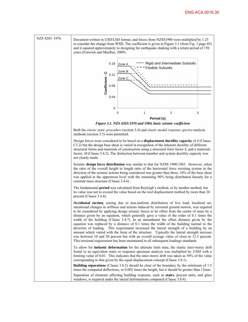
NZS 4203: 1976 Document written in USD/LSD format, and forces from NZSS1900 were multiplied by 1.25
to consider the change from WSD. The coefficient is given in Figure 3.1 (from Fig. 3 page 45) and it equated approximately to designing for earthquake shaking with a return period of 150 years (Fenwick and MacRae, 2009).
Figure 3.1. NZS 4203:1976 and 1984, basic seismic coefficient Both the elastic static procedure (section 3.4) and elastic modal response spectra analysis methods (section 3.5) were permitted.
Design forces were considered to be based on a displacement ductility capacity of 4 (Clause C3.2) but the design base shear is varied in recognition of the inherent ductility of different structural forms and materials of construction using a structural form factor S, and a materials factor, M (Clause 3.4.2). The distinction between member and system ductility capacity was not clearly made.
Seismic design force distribution was similar to that for NZSS 1900:1965. However, when the ratio of the overall height to length ratio of the horizontal force resisting system in the direction of the seismic actions being considered was greater than three, 10% of the base shear was applied at the uppermost level with the remaining 90% being distributed linearly for a constant mass structure (Clause 3.4.6).
The fundamental period was calculated from Rayleigh’s method, or by another method, but its value was not to exceed the value based on the roof displacement method by more than 20 percent (Clause 3.4.4).
Accidental torsion, arising due to non-uniform distribution of live load, localised un-intentional changes in stiffness and actions induced by torsional ground motion, was required to be considered by applying design seismic forces to be offset from the centre of mass by a distance given by an equation, which generally gave a value of the order of 0.1 times the width of the building (Clause 3.4.7). In an amendment the offset distance given by the equation was replaced by a distance of 0.1 times the width of the building normal to the direction of loading. This requirement increased the lateral strength of a building by an amount which varied with the form of the structure. Typically the lateral strength increase was between 10 and 20 percent but with an overall average value of close to 12.5 percent. This torsional requirement has been maintained in all subsequent loadings standards.
To allow for inelastic deformation for the ultimate limit state, the elastic inter-storey drift found in an equivalent static or response spectrum analysis was multiplied by 2/SM with a limiting value of 0.01. This indicates that the inter-storey drift was taken as 50% of the value corresponding to that given by the equal displacement concept (Clause 3.8.1).
Building separations (Clause 3.8.2) should be clear of the boundary by the minimum of 1.5 times the computed deflections, or 0.002 times the height, but it should be greater than 12mm.
Separation of elements affecting building response, such as stairs, precast units, and glass windows, is required under the lateral deformations computed (Clause 3.8.4).
0
0.04
0.08
0.12
0.16
Co
eff
icie
nt
- C
Zone A
Zone B
Zone C
0 1 2 3
Period (s)
Rigid and Intermediate SubsoilsFlexible Subsoils
ENG.ACA.0016.30
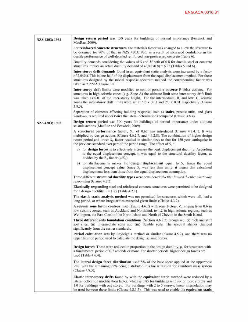
NZS 4203: 1984 Design return period was 150 years for buildings of normal importance (Fenwick and MacRae, 2009).
For reinforced concrete structures, the materials factor was changed to allow the structure to be designed for 80% of that in NZS 4203:1976, as a result of increased confidence in the ductile performance of well-detailed reinforced non-prestressed concrete (Table 6).
Ductility demands considering the values of S and M both of 0.8 for ductile steel or concrete structures implies an actual ductility demand of 4/(0.8x0.8) = 6.25 (Tables 5 and 6).
Inter-storey drift demands found in an equivalent static analysis were increased by a factor of 2.0/SM. This is one-half of the displacement from the equal displacement method. For these structures designed by the modal response spectrum method the corresponding factor was taken as 2.2/SM (Clause 3.8).
Inter-storey drift limits were modified to control possible adverse P-delta actions. For structures in high seismic zones (e.g. Zone A) the ultimate limit state inter-storey drift limit was taken as 0.01 of the inter-storey height. For the intermediate, B, and low, C, seismic zones the inter-storey drift limits were set at 5/6 x 0.01 and 2/3 x 0.01 respectively (Clause 3.8.3).
Separation of elements affecting building response, such as stairs, precast units, and glass windows, is required under twice the lateral deformations computed (Clause 3.8.4).
NZS 4203; 1992 Design return period was 500 years for buildings of normal importance under ultimate seismic actions (MacRae and Fenwick, 2009)
A structural performance factor, Sp, of 0.67 was introduced (Clause 4.2.4.1). It was multiplied by design actions (Clause 4.6.2.7, and 4.6.2.8). The combination of higher design return period and lower Sp factor resulted in similar sizes to that for 150 year earthquake in the previous standard over part of the period range. The effect of Sp :
a) for design forces is to effectively increases the peak displacement ductility. According to the equal displacement concept, it was equal to the structural ductility factor, µ, divided by the Sp factor (µ/Sp),
b) for displacements makes the design displacement equal to Sp times the equal displacement concept value. Since Sp was less than unity, it means that calculated displacements less than those from the equal displacement assumption.
Three different structural ductility types were considered: ductile; limited ductile; elastically responding (Clause 4.2.2).
Elastically responding steel and reinforced concrete structures were permitted to be designed for a design ductility = 1.25 (Table 4.2.1)
The elastic static analysis method was not permitted for structures which were tall, had a long period, or where irregularities exceeded given limits (Clause 4.3.2).
A seismic zone factor contour map (Figure 4.6.2) with zone factors, Z, ranging from 0.6 in low seismic zones, such as Auckland and Northland, to 1.2 in high seismic regions, such as Wellington, the East Coast of the North Island and North of Cheviot in the South Island.
Three different soils foundation conditions (Section 4.6.2.2) recognised; (i) rock and stiff soil sites, (ii) intermediate soils and (iii) flexible soils. The spectral shapes changed significantly from the earlier standards.
Period calculation was by Rayleigh’s method or similar (clause 4.5.2), and there was no upper limit on period used to calculate the design seismic forces. Design forces: These were reduced in proportion to the design ductility, , for structures with a fundamental period of 0.7 seconds or more. For shorter periods, higher design forces are used (Table 4.6.4).
The lateral design force distribution used 8% of the base shear applied at the uppermost level with the remaining 92% being distributed in a linear fashion for a uniform mass system (Clause 4.8.3);
Elastic inter-storey drifts found by with the equivalent static method were reduced by a lateral deflection modification factor, which is 0.85 for buildings with six or more storeys and 1.0 for buildings with one storey. For buildings with 2 to 5 storeys, linear interpolation may be used between these limits (Clause 4.8.1.5). This was used to enable the equivalent static
ENG.ACA.0016.31
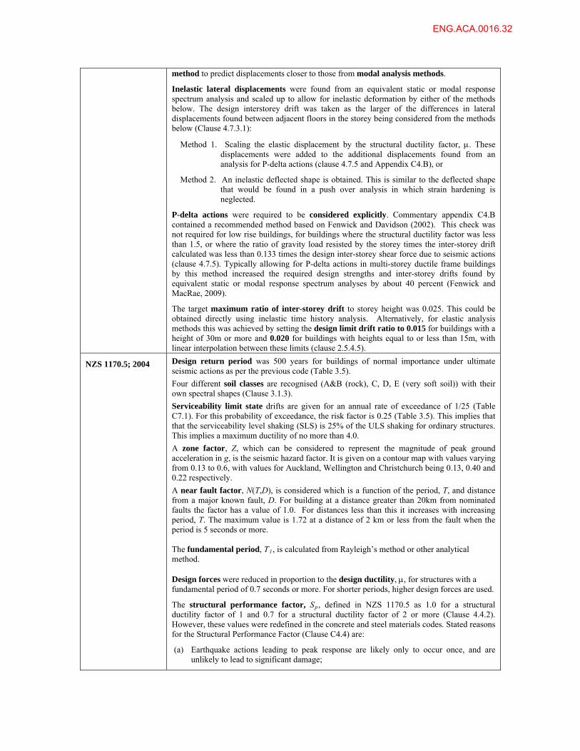
method to predict displacements closer to those from modal analysis methods.
Inelastic lateral displacements were found from an equivalent static or modal response spectrum analysis and scaled up to allow for inelastic deformation by either of the methods below. The design interstorey drift was taken as the larger of the differences in lateral displacements found between adjacent floors in the storey being considered from the methods below (Clause 4.7.3.1):
Method 1. Scaling the elastic displacement by the structural ductility factor, . These displacements were added to the additional displacements found from an analysis for P-delta actions (clause 4.7.5 and Appendix C4.B), or
Method 2. An inelastic deflected shape is obtained. This is similar to the deflected shape that would be found in a push over analysis in which strain hardening is neglected.
P-delta actions were required to be considered explicitly. Commentary appendix C4.B contained a recommended method based on Fenwick and Davidson (2002). This check was not required for low rise buildings, for buildings where the structural ductility factor was less than 1.5, or where the ratio of gravity load resisted by the storey times the inter-storey drift calculated was less than 0.133 times the design inter-storey shear force due to seismic actions (clause 4.7.5). Typically allowing for P-delta actions in multi-storey ductile frame buildings by this method increased the required design strengths and inter-storey drifts found by equivalent static or modal response spectrum analyses by about 40 percent (Fenwick and MacRae, 2009).
The target maximum ratio of inter-storey drift to storey height was 0.025. This could be obtained directly using inelastic time history analysis. Alternatively, for elastic analysis methods this was achieved by setting the design limit drift ratio to 0.015 for buildings with a height of 30m or more and 0.020 for buildings with heights equal to or less than 15m, with linear interpolation between these limits (clause 2.5.4.5).
NZS 1170.5; 2004 Design return period was 500 years for buildings of normal importance under ultimate seismic actions as per the previous code (Table 3.5).
Four different soil classes are recognised (A&B (rock), C, D, E (very soft soil)) with their own spectral shapes (Clause 3.1.3).
Serviceability limit state drifts are given for an annual rate of exceedance of 1/25 (Table C7.1). For this probability of exceedance, the risk factor is 0.25 (Table 3.5). This implies that that the serviceability level shaking (SLS) is 25% of the ULS shaking for ordinary structures. This implies a maximum ductility of no more than 4.0.
A zone factor, Z, which can be considered to represent the magnitude of peak ground acceleration in g, is the seismic hazard factor. It is given on a contour map with values varying from 0.13 to 0.6, with values for Auckland, Wellington and Christchurch being 0.13, 0.40 and 0.22 respectively.
A near fault factor, N(T,D), is considered which is a function of the period, T, and distance from a major known fault, D. For building at a distance greater than 20km from nominated faults the factor has a value of 1.0. For distances less than this it increases with increasing period, T. The maximum value is 1.72 at a distance of 2 km or less from the fault when the period is 5 seconds or more. The fundamental period, T1, is calculated from Rayleigh’s method or other analytical method. Design forces were reduced in proportion to the design ductility, , for structures with a fundamental period of 0.7 seconds or more. For shorter periods, higher design forces are used.
The structural performance factor, Sp, defined in NZS 1170.5 as 1.0 for a structural ductility factor of 1 and 0.7 for a structural ductility factor of 2 or more (Clause 4.4.2). However, these values were redefined in the concrete and steel materials codes. Stated reasons for the Structural Performance Factor (Clause C4.4) are:
(a) Earthquake actions leading to peak response are likely only to occur once, and are unlikely to lead to significant damage;
ENG.ACA.0016.32
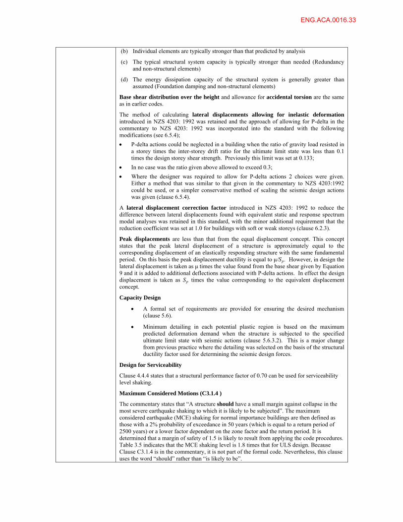
(b) Individual elements are typically stronger than that predicted by analysis
(c) The typical structural system capacity is typically stronger than needed (Redundancy and non-structural elements)
(d) The energy dissipation capacity of the structural system is generally greater than assumed (Foundation damping and non-structural elements)
Base shear distribution over the height and allowance for accidental torsion are the same as in earlier codes.
The method of calculating lateral displacements allowing for inelastic deformation introduced in NZS 4203: 1992 was retained and the approach of allowing for P-delta in the commentary to NZS 4203: 1992 was incorporated into the standard with the following modifications (see 6.5.4);
P-delta actions could be neglected in a building when the ratio of gravity load resisted in a storey times the inter-storey drift ratio for the ultimate limit state was less than 0.1 times the design storey shear strength. Previously this limit was set at 0.133;
In no case was the ratio given above allowed to exceed 0.3;
Where the designer was required to allow for P-delta actions 2 choices were given. Either a method that was similar to that given in the commentary to NZS 4203:1992 could be used, or a simpler conservative method of scaling the seismic design actions was given (clause 6.5.4).
A lateral displacement correction factor introduced in NZS 4203: 1992 to reduce the difference between lateral displacements found with equivalent static and response spectrum modal analyses was retained in this standard, with the minor additional requirement that the reduction coefficient was set at 1.0 for buildings with soft or weak storeys (clause 6.2.3).
Peak displacements are less than that from the equal displacement concept. This concept states that the peak lateral displacement of a structure is approximately equal to the corresponding displacement of an elastically responding structure with the same fundamental period. On this basis the peak displacement ductility is equal to μ/Sp. However, in design the lateral displacement is taken as μ times the value found from the base shear given by Equation 9 and it is added to additional deflections associated with P-delta actions. In effect the design displacement is taken as Sp times the value corresponding to the equivalent displacement concept.
Capacity Design
A formal set of requirements are provided for ensuring the desired mechanism (clause 5.6).
Minimum detailing in each potential plastic region is based on the maximum predicted deformation demand when the structure is subjected to the specified ultimate limit state with seismic actions (clause 5.6.3.2). This is a major change from previous practice where the detailing was selected on the basis of the structural ductility factor used for determining the seismic design forces.
Design for Serviceability
Clause 4.4.4 states that a structural performance factor of 0.70 can be used for serviceability level shaking.
Maximum Considered Motions (C3.1.4 )
The commentary states that “A structure should have a small margin against collapse in the most severe earthquake shaking to which it is likely to be subjected”. The maximum considered earthquake (MCE) shaking for normal importance buildings are then defined as those with a 2% probability of exceedance in 50 years (which is equal to a return period of 2500 years) or a lower factor dependent on the zone factor and the return period. It is determined that a margin of safety of 1.5 is likely to result from applying the code procedures. Table 3.5 indicates that the MCE shaking level is 1.8 times that for ULS design. Because Clause C3.1.4 is in the commentary, it is not part of the formal code. Nevertheless, this clause uses the word “should” rather than “is likely to be”.
ENG.ACA.0016.33
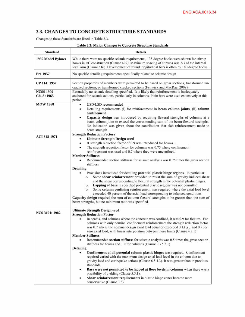
3.3. CHANGES TO CONCRETE STRUCTURE STANDARDS
Changes to these Standards are listed in Table 3.3.
Table 3.3: Major Changes to Concrete Structure Standards
Standard Details
1935 Model Bylaws While there were no specific seismic requirements, 135 degree hooks were shown for stirrup hooks in RC construction (Clause 409). Maximum spacing of stirrups was 2/3 of the internal level arm (Clause 616). Development of round longitudinal bars is often by 180 degree hooks.
Pre 1957 No specific detailing requirements specifically related to seismic design.
CP 114: 1957 Section properties of members were permitted to be based on gross sections, transformed un-cracked sections, or transformed cracked sections (Fenwick and MacRae, 2009).
NZSS 1900 Ch. 8 :1965
Essentially no seismic detailing specified. It is likely that reinforcement is inadequately anchored for seismic actions, particularly in columns. Plain bars were used extensively at this period.
MOW 1968 USD/LSD recommended Detailing requirements (i) for reinforcement in beam column joints, (ii) column
confinement. Capacity design was introduced by requiring flexural strengths of columns at a
beam column joint to exceed the corresponding sum of the beam flexural strengths. No indication was given about the contribution that slab reinforcement made to beam strength.
ACI 318-1971 Strength Reduction Factors
Ultimate Strength Design used A strength reduction factor of 0.9 was introduced for beams. The strength reduction factor for columns was 0.75 where confinement
reinforcement was used and 0.7 where they were unconfined. Member Stiffness
Recommended section stiffness for seismic analysis was 0.75 times the gross section stiffness
Detailing Provisions introduced for detailing potential plastic hinge regions. In particular:
o Some shear reinforcement provided to resist the sum of gravity induced shear and the shear corresponding to flexural strength in the potential plastic hinges.
o Lapping of bars in specified potential plastic regions was not permitted. o Some column confining reinforcement was required where the axial load level
exceeded 40 percent of the axial load corresponding to balanced conditions Capacity design required the sum of column flexural strengths to be greater than the sum of beam strengths, but no minimum ratio was specified.
NZS 3101: 1982 Ultimate Strength Design used Strength Reduction Factor
In beams, and columns where the concrete was confined, it was 0.9 for flexure. For columns with only nominal confinement reinforcement the strength reduction factor was 0.7 where the nominal design axial load equal or exceeded 0.1Agf’c and 0.9 for zero axial load, with linear interpolation between these limits (Clause 4.3.1)
Member Stiffness Recommended section stiffness for seismic analysis was 0.5 times the gross section
stiffness for beams and 1.0 for columns (Clause C3.5.5.1) Detailing
Confinement of all potential column plastic hinges was required. Confinement required varied with the maximum design axial load level in the column due to gravity load and earthquake actions (Clause 6.5.4.3). It was greater than in previous standards.
Bars were not permitted to be lapped at floor levels in columns when there was a possibility of yielding (Clause 5.5.1).
Shear reinforcement requirements in plastic hinge zones became more conservative (Clause 7.3).
ENG.ACA.0016.34

Specific steel rebar antibuckling considerations for rebars in potential hinge regions (Clause 6.5.3.3b).
Joint shear reinforcement development requirements and reinforcing increased (Clause 9.5).
Column ties anchored by 135o bends in cover concrete (Clause 5.5.5.3). Beam bars in external joint zones likely to be bent away from the joint zone core. Columns not designed for earthquake with = 0.70 are permitted to have 6mm
reinforcement at a spacing no greater than (i) the minimum column cross sectional dimension, (ii) 16 times the longitudinal bar diameter, and (iii) 48 times the transverse bar diameter (Clause 6.4.7.1b, 6.4.7.2b).
Capacity Design Many requirements introduced. Overstrength moments in beams were taken as 1.25 or 1.4 times the ideal flexural
strength of beams with grade 275 and 380 steel respectively (Clause C3.5.1.3). Design for a Strong-Column Weak-Beam frame mechanism was specified in the
commentary (Appendix C3A). This encouraged potential primary plastic regions to be in the beams except at the column bases. To obtain the column design actions for flexure, shear and axial force, this included considering:
o the maximum beam over-strength moments that could be applied to a joint which affected the corresponding static column demands,
o changes in distribution of column moments due to higher elastic and inelastic mode behaviour, with a dynamic magnification factor,
o bi-axial moments on columns which were part of 2 orthogonal frames, and o effects of beams yielding simultaneously over the frame
The required minimum ratio of the sum of the nominal column flexural strengths to the sum of the nominal beam flexural strengths at beam-column joint centreline in one way frames ranged from 1.6 to 2.4. In many cases the minimum ratios were exceeded as the flexural strengths of the column changed between the top and bottom of the joint zone and for practical purposes the same longitudinal reinforcement was used in the column on each side of the joint zone. This method of designing columns for seismic actions was adopted into NZS 3101:1995 and retained with minor modifications in NZS 3101: 2006.
An effective width of floor slab (usually 2 to 4 times the depth of the slab measured from the column faces) was assumed to contribute to beam over-strength (Clause 6.5.3.2 (e), which was smaller than that in later standards.
Diaphragm Design (Section 10.5.6).
Floors are designed for the smaller of the maximum forces that could be resisted by the lateral force system, or for the forces from the “parts and portions” section of the loadings standard.
Nominal requirements were given for reinforcement to tie the floor into the building and for the use of precast flooring elements
NZS 3101: 1995 Ultimate Strength Design used.
Building Classifications (4.4.1) are: Elastically responding, Limited ductile, and Ductile buildings.
Strength Reduction Factor The strength reduction factor for flexure in beams and flexure and axial load in
columns was 0.85. (The option of using a nominally un-confined column with a strength reduction factor of 0.7 was removed). (Clause 3.4.2.2)
The maximum ductility was set as 6 for concrete structures. This overrode the larger values permitted by NZS 4203:1992.
Member Stiffness Recommended section stiffness for seismic analysis was 0.4 times the gross section
stiffness for rectangular beams and and 0.35 for Tee and L beams. For columns the value varied from 0.4Ig for an axial tension of ratio (N*/(Agfc
’)) of -0.05, 0.6Ig at a
ENG.ACA.0016.35
g at a ratio of 0.8, with interpolation for intermediate axial load ratios (clause C 3.4.3.3).
Bay elongation effects (i.e. elongation of plastic hinges in the beams pushing the columns apart)
Requirements for the minimum length of support ledges for precast floor components to minimize the possibility of units supported on small ledges and/or on cover concrete (Clause 4.3.6.4).
Effective width of slab to contribute to beam moment flexural strength was increased and assumed to be the same in both loading directions (Clause 8.5.3.3).
Effective anchorage of slab reinforcement required (Clause 4.3.6.6)
Considerations were made for increase in shear force in the first storey columns and the formation of a plastic hinge forming in the columns adjacent to the first level beams. (Although these are not likely to govern). (Fenwick and MacRae, 2009)
Details
Confinement of columns increased for columns with a high axial load (Section 7.5).
Confinement for gravity columns, which were not designed to resist seismic actions, was required (Clause 8.4.7). Here, amongst other requirements, the spacing of transverse steel is no greater than (i) one third the minimum column cross sectional dimension, (ii) 10 times the longitudinal bar diameter.
Beam-column joint reinforcement requirements revised and reduced compared with the 1982 edition (Clause 11.3.7)
Minimum seating lengths for precast floor components after reasonable allowance for construction tolerances were set as the larger of 1/180 of the clear span or 50mm for solid slabs or hollow-core units and 75mm for ribbed members (Clause 4.3.6.4).
Stairs consider the seating lengths of NZS4203:1992 (Clause 4.4.13.2).
NZS 3101: 2006 Building Classifications : For consistency with NZS 1170.5 three classifications were defined for buildings.
These relate to the value of the structural ductility factor used to determine the seismic design actions. They are:
o nominally ductile, using a design ductility of 1.25, o limited ductile, and o ductile buildings.
Three classifications of potential plastic regions were defined. Each of these have different detailing requirements and inelastic capacities (Clause 2.6.1.3). They are:
o nominally ductile plastic regions, o limited ductile plastic regions, and o ductile plastic regions.
There is no direct connection between the type of plastic region and classification of a building.
Design of brittle elements is excluded from this Standard o Values for structural ductility factor of less than 1.25 are not given.
Sp values given in NZS 1170.5 were replaced by 0.9 for a structural ductility factor, μ, of 1.25, and 0.7 for a structural ductility factor of 3 or more, with linear interpolation between these limits (Clause 2.6.2.2).
Materials :
Welded wire fabric, with a strain capacity less than 10% is permitted only in situations where it will not yield in ULS shaking, or when if it does yield or rupture the integrity of the structure is not affected (Clause 5.3.2.7).
Member Stiffness
Minor revisions were made to the section stiffness where a high grade reinforcement was used (Clause C6.9.1).
ENG.ACA.0016.36
Capacity design 2.6.5 Contribution of prestressed floor components to over-strength of beams is
considered (Clause 9.4.1.6.2). The difference in effective widths of floor slabs contributing to nominal negative
moment flexural strength of beams and to over-strength of beams is considered (Clauses 9.4.1.6.1 and 9.4.1.6.2).
Two methods are permitted for assessing capacity design actions in columns: o The first method is based on the one contained in NZS 3101: 1995 Appendix A
with modifications to consider bi-axial actions more directly and to allow for the effects of elongation of beams on plastic hinge locations. In this method, each column above the primary plastic hinge located at its base of the column is proportioned and detailed with the aim of minimising inelastic deformation that may occur (Method A in Appendix D, clause D3.2).
o The second method permits a limited number of potential plastic hinges in the columns provided the remaining columns have sufficient nominal strength to ensure that the storey column sway shear strength exceeds the storey beam sway shear strength in each storey by a nominated margin. The beam sway storey shear strength is calculated assuming over-strength actions are sustained in all the potential plastic regions associated with the storey being considered (Appendix D, clause D3.3). This method has more restrictions on the lap positions of longitudinal bars and requiring more confinement reinforcement than the first method.
(b) The significance of elongation of plastic hinges in beams on the actions in columns is recognised. In particular elongation can cause plastic hinges, which are not identified in standard analyses, to form in columns immediately above or below the first elevated level. This can increase the shear forces induced in the columns. However, as the requirement for confinement reinforcement is generally more critical than shear reinforcement this is unlikely to be critical for the shear strength of these columns (see 10.4.7.1.2, B8.4, C2.6.1.3.3, C5.3.2, C10.4.6.6, C10.4.7.2.1)
(c) In calculating over-strength actions in beams, allowance needs to be made for the possible material strengths and the increase in stress that may be sustained due to strain hardening. Strain levels are much higher in over-strength conditions than in normal ultimate strength design conditions. As strain levels increase the width of floor slab that acts with a beam increases. Consequently a greater width of slab needs to be assumed to contribute to over-strength than to design strength. This effect is recognised in the NZS 3101: 2006 (Clauses 9.4.1.6.1 and 9.4.1.6.2) but it was not recognised in earlier standards.
(e) Precast prestressed floor units in a floor slab, which span past potential plastic hinges in a beam, can make a very significant difference to the over-strength capacity of plastic hinges. A method of assessing the strength due to this source is given in the Standard (Clause 9.4.1.6.2).
Strength design
Primary plastic hinges detailed in terms of likely ultimate limit state inelastic demands. These demands are written in terms section curvature for a specified plastic hinge length, which is similar to specifying a plastic rotation (see Clause 2.6.1). Serviceability Limit State with Earthquake
New requirements for fully ductile (but not nominal or limited ductile structures). (Clause 2.6.3.1).
The structural ductility that can be used in the ultimate limit state (ULS) is limited to 6 for buildings of normal importance and in some cases a lower value is required (Clause 2.6.1.2d).
For the serviceability limit-state a structural ductility factor of 1 is required for SLS1, but a value of 2 may be used for SLS2 (Clause 2.6.2.3.1). However, SLS2 is only applied to buildings of high importance (NZS 1170: 2004, Clause 5, 2.1.4).
Clause 2.6.3.1 requires either that:
ENG.ACA.0016.37
o (i) the serviceability design strength is equal to, or exceeds, the serviceability design actions, or
o (ii) an analysis shows that crack widths and deflections remaining after a serviceability limit-state earthquake are acceptable considering the effect of inelastic deformation caused by moment redistribution and other shake down effects associated with repeated inelastic displacements during an earthquake.
Strength requirements for the serviceability limit state are related to the average strength of structural sections. This is taken as the nominal strength with a strength reduction factor of 1.1 (Clause 2.6.3.2) to correspond to average material strengths.
Diaphragm Design
Similar material to NZS 3101: 1995
Strut and tie analysis required for forces induced in the diaphragms associated with the ultimate limit-state, or with actions associated with over-strength in potential plastic regions (Clause 13.3.3)
Floors containing precast prestressed units have special requirements (NZS 3101: 2006 plus Amendment 2) relating to (Fenwick and MacRae, 2009):
Limiting the possibility of the floors falling off supports (Clause 18.7.4). Limiting the possibility of brittle failure by
o Requiring for low friction bearing strips with hollow-core units (Clause 18.7.4);
o Requiring a thin linking slab between a precast unit and a parallel structural element, such as a beam or wall, which may deflect in a vertical direction relative to the precast unit. This is required to prevent the load transfer between the structural elements causing the precast units to fail (Clause 18.6.7.2);
o Specifying requirements for shear strength of precast units in zones where over-strength actions can cause tensile stresses to be induced on the top surface of the precast units. In this situation the shear strength is reduced to a value comparable with a non-prestressed beam of the same dimensions (Clause 19.3.11.2.4);
o Specifying the position where reinforcement connecting the precast unit to the supporting structure is cut off or reduced is based on the capacity of the floor to sustain the negative moments and axial tension. These may be induced in the floor when over-strength actions act at the supports and vertical ground motion induces negative moments in the floor (Clause 19.4.3.6);
o Cautioned against supporting precast units on structural elements that may deform and induce torsional moments as these may lead to torsional failure of the floor unit. This situation can be critical for hollow-core flooring (Clause C19.4.3.6).
ENG.ACA.0016.38
3.4. CHANGES TO STEEL STRUCTURE STANDARDS
Changes to these standards dealing with steel structures are listed in Table 3.4.
Table 3.4: Major Changes to Steel Structure Standards
Standard Details
1935 Model Bylaws No specific seismic provisions. Members connected with rivets and some bolts (clauses 706-708. For b1/tf ratios > 20 for beams and 16 for angles the strength was decreased (Clause 713, 724).
NZS 3404-1976 This standard was produced to assist designers to meet the ductility, capacity design and concurrent effects considerations required by NZS 4203. It drew heavily on plastic design considerations and used Allowable Stress Design (ASD/WSD). It was regarded as an interim standard while a new standard for NZ requirements including limit state design and seismic requirements was developed (Spring and Butcher, 1985).
AS 1250-1981 No specific seismic provisions and used Allowable Stress Design (ASD/WSD). However plastic design provisions included:
Section requirements (Clause 10.8)
o Flange outstand b1/tf ratio limited to 136/√Fy = 8.60 for Grade 250 steel.
o Web outstand d1/tw ratio limited to 512/√Fy = 32 for Grade 250 steel.
Member requirements (Clause 10.9)
o Lateral restraints required in plastic hinging region, defined as when moment demand > 0.85Mpc. with spacing dependent on weak axis radius of gyration, yield stress and expected rotation.
o Web outstand d1/tw ratio limited to 512/√Fy = 32 for Grade 250 steel.
Maximum axial forces
o of 33% of the Euler buckling loads (Clause 10.7)
o limited by member slenderness and moment ratio to encourage yielding at the member ends (Clause 10.5.3, 10.5.4). This is the end yielding criteria requirement.
o in a plastic hinge zone limited web slenderness ratio (Clause 10.8.3)
NZS 3404:1989 Both parts of this document are read in conjunction with AS1250-1981. Part 1 describes the effects that should be considered, while Part 2 (P2) describes how they may be considered. This document is used in conjunction with NZS 4203. In Part 1, Chapter 12 “Provisions for Seismic Design” was new.
Limit State Design / Ultimate Strength Design is used so appropriate modifications were made to AS1250:1981.
Structural classifications (Clause 12.2.3, 12.2.4) of:
Fully ductile (Category 1) with strain hardening expected, > 2.0
Limited Ductility (Category 2) with no strain hardening expected, 2.0 > > 1.25
Nominally elastic or fully elastic structures (Category 3A or 3B), with no significant yielding, < 1.25
Member classifications (Clause 12.2.5) of:
Members subject to high ductility demand (Category 1) as primary elements of Category 1 structure
Members subject to low ductility demand (Category 2) as
o primary elements of Category 2 structure, or as
o secondary elements of Category 1 structure
Members subject to very low or no ductility demand (Category 3A or 3B). These members are required to reach first yield.
Damping Values (P2 Table 12.4)
Recommended to be between 2% and 15% for clad structures depending on welding type and ductility level.
ENG.ACA.0016.39
Materials Factor (Clause 12.2.7), M of 0.8 permitted to acknowledge high ductility capacity.
Lateral Deflection limits (Clause 12.8.3) follow NZS4203 except that:
A P-delta requirement is more severe for structures in zones of low seismicity than that in zones of high seismicity following the approach of Andrews (1977).
Capacity Design (Clause 12.2.7) is specified for Category 1, 2 or 3 structures.
Overstrength values recommended are given in P2 Table 12.3 (Clause 12.2.8). They have values up to 1.70. Grades 250 and 350 steel only specified.
Connections are to be designed to minimum of overstrength forces, or those for fully elastic structural response (Clause 12.9.1.2).
Panel zones are designed to resist the moments associated with 1.15Mp from the beams on either side or a lower value based on analysis (P2 Clause 12.9.5.2b).
Concurrent actions are considered under the design level shaking by limiting the full seismic induced actions to those in the moment-axial force interaction equation, with an upper limit of 1.50 rather than unity (P2 Clause 12.8.5).
Axial force limits (P2 12.8.4.1)
Column axial force ratio limits, Pu/Py, were 0.50, 0.70 or 1.0 for Category 1, 2 and 3 columns respectively. They also had to satisfy the end yielding criteria requirement (P2 Clause 12.8.4.2) which is the same as that from AS1250.
Detailing
Web and flange slenderness ratios specified for all member categories. These are similar to those in AS1250 plastic design section, but become less severe for members with less expected ductility demand.
Spacing of lateral restraints is similar to AS1250 for Category 2 members, but is more severe for Category 1 members.
Splices are required to be clear of plastic hinge zones (Clause 12.9.6). No specific design forces are specified, and non-seismic splice design example is recommended from AISC 1985. (P2 C 12.31)
Detailed Design Guidance and parameters are given for:
Moment Frames (P2 Clause 12.10)
Eccentrically Braced Frames (P2 Clause 12.11)
Concentrically Braced Frames (P2 Clause 12.12)
Dual Systems (P2 Clause 12.13)
NZS 3404:1992 This document combines Parts 1 and 2 from the 1989 edition, and incorporates the AS 4100:1990 provisions. The seismic sections in this document were not significantly changed apart from the following:
Structural/Member Classifications
Categories 3A and 3B were separated with Category 3B structures now being designed for = 1.0. (Table 12.2.4)
Details
Lateral bracing requirements became more stringent for yielding members also carrying axial force.
Column splices were not necessarily designed to resist more than 50% of the ideal section capacity for either columns in or out of the major seismic system (Clause 12.9.2).
Capacity Design
Panel zones are designed not to be the major energy dissipating elements unless small frame ductilities are expected (Cl 12.9.5.2). This is more severe than the 1989 standard.
Connections and members do not need to resist strengths greater than nominally elastic ( = 1.25) response for Category 1 or Category 2 seismic resisting systems with an actual system ductility (act) greater than 1.25. This clause relies on
ENG.ACA.0016.40
Concurrent actions for two directions of loading are required on members which are part of orthogonal category 1 frames. However, if one, or both frames is not category 1, the demands considered are reduced. (Clause 12.8.4)
Plastic Hinge Rotation Limits (Clause 4.7.2)
These are specified for different member categories and axial force levels for both earthquake and non-earthquake actions.
Column Axial Force Limits (Clause 12.8.3)
Column axial force ratio limits, Pu/Py, were 0.50, 0.70, 0.80 or 1.0 for Category 1, 2, 3A and 3B columns respectively. They also had to satisfy the end yielding criteria requirement (Clause 12.8.3.2) which is the same as that from AS1250.
NZS 3404:1997 BHP replaced most of their Grade 250 steel sections with new fy = 300 MPa steel. This necessitated a number of changes. Seismic clauses did not change markedly.
NZS 3404:1997 Amendments 1 & 2 (2007)
Amendment 2 focuses on meeting requirements of NZS 1170.5, namely: no structural damage under SLS event dependable strength, stiffness, ductility under ULS event no collapse under MCE event
Materials modifications (Clause 2.2, Table 2.6.4.4) were needed after fractures seen in Northridge 1994 and Kobe 1995 earthquakes. These are met by New Zealand and Australian steels. Also, a new seismic grade (S0) steel is being developed. Amendment
makes clear which properties are from the test certificate or mill test report and which from the material supply standard
introduces minimum Charpy Impact provisions for steels expected to respond inelastically
Column maximum axial forces were updated to be no more than:
28% of the Euler buckling loads (Clause 4.9.1) those based on end yield criteria information for hinging members. They became
less conservative (Clause 8.4.3.2.1) Structural performance factors, Sp, modified from NZS1170.5:
For the serviceability limit state: Sp = 0.7 For the ultimate limit state: Sp = 0.7, if all elements of system meet category 2 for
Category 3 and 4 structures. Otherwise, Sp = 0.9. Relationship between structure category and member category was made more severe (Table 12.2.6) Capacity Design of Frames
Aim of procedures is to: o develop inelastic action in primary element o suppress inelastic action in columns and connections (except for semi-
rigid systems) at DLE o based on structure forming a yielding mechanism for column capacity
design derived design action determination Slab Participation Factor increases the flexural overstrength in steel moment
frames. Alternatively, the slab may be isolated from the column (Clause 12.10.2.4) Maximum actions on members (Clause 12.3.3.4)
Nominally ductile seismic response for μact ≥ 1.8 and with Sp = 0.7 Elastic seismic response for μact < 1.8 and with Sp = 0.7 for category 2 systems and
0.9 for category 3 (and 4) systems A method was given for calculation of μact. Maximum actions on Connections (Clause 12.9.1.2.2)
Three sets of upper bound actions exist, intended to ensure that the connection strength is always higher than the strength of the primary elements of the seismic resisting system. The lowest this ratio can be is 1.25 for category 1, 2 and 3 systems
ENG.ACA.0016.41
3-15
Splice Capacities
Splices in compression columns are required to be designed for 30% of the member flexural capacity and 15% of the member design shear capacity in simple construction. If rigid construction, they must be designed for 50% of the member flexural capacity. (Clause 9.1.4.1(i, ii, vi))
Splices in seismic-resisting systems require higher design actions from (Clause 12.9.2.2)
Member Capacities
EBF Inelastic rotation angles slightly decreased to allow for MCE and to align with latest USA practice (Clause 12.11.3.3.1)
Gusset plates are designed for combined compression and bending considering eccentric loading (Clause 9.1.3.5) as well as for opening and closing of connecting members (Clause 12.9.7.4). While not specifically stated, methods of meeting these requirements, as stated in the commentary, are likely to also be sufficient to consider gusset plate out-of-plane deformation that may occur as a result of brace buckling.
ENG.ACA.0016.42
4. IMPROVEMENT OF CURRENT STANDARDS The following suggestions are made to improve current seismic design standards:
(a) Standards Related
1. Means of Building Egress, such as stairs or elevators, should be designed and constructed not to fail under the maximum displacements that an earthquake may impose on a structure.
These maximum displacements may be significantly greater than those from the Maximum Considered Earthquake (MCE) shaking as shown from 22 February 2011 Christchurch Earthquake. The provisions should consider all parameters that can influence the demands including:
a) the relationship between inelastic and elastic single-degree-of-freedom performance.
b) the likely inelastic effect on the deformed shape of the structure, c) the Structural Performance factor (which currently reduces design
displacement demands), and d) any frame gapping behaviour.
2. The Structural Performance Sp factor
2.1 The Introduction of the Sp factor Two major changes were made to the design spectra from NZS 4203: 1984 to NZS 4203: 1992. The first was shifting from the 150 year return period for the ULS earthquake for a normal importance building, used in 1984, to the 500 year return period, in order to provide consistency with international limit state practice. The second was basing the shape of the spectra on the engineering seismology derived elastic response curve, rather than the previous more simplistic inelastic response curve used in earlier versions of the loadings standard. The effect of these changes was to increase the seismic design forces on many buildings. However, the committee at the time noted that the observed performance of buildings in earthquakes, which in magnitude similar to that on which the design was based, performed better than would have been predicted. On this basis the structural performance factor, Sp factor, was introduced and set at a level of 0.67 and it was used to multiply the theoretical spectrum to give the spectrum used for design. US design codes had factors which worked in a similar manner to reduce the design spectrum. However, in the US case the factors equivalent to the Sp factor varied in magnitude depending on the structural type and construction material.
Fenwick and MacRae (2009) showed that the change from the 150 year design return period earthquake to the 500 year design return period earthquake in 1992, together
ENG.ACA.0016.43

with other associated changes including the Sp factor, increased the equivalent static base design shear strengths for all but the buildings in Wellington with a period greater than 2.5s. In general it reduced the ductility demands and increased the stiffnesses. However, further changes associated with the 1995-2006 Standards resulted in stiffness reductions that were most significant for reinforced concrete frames. The Concrete Structures standard in 1995 reduced the recommended section stiffnesses especially for beams, resulting in a given frame being analysed as more flexible, with higher period and hence reduced earthquake demand than the corresponding values found using the earlier versions of the structural concrete and loadings standards. There was no such change in steel frame stiffesses for use in design over that period. The result was a stiffness reduction of some 11% for steel frames and a greater value for concrete frames. 2.2 The purpose of the Sp factor The stated purpose of the Sp factor according to the NZS1170.5 C4.4 is to consider that:
a) Earthquake actions leading to peak response are likely to occur only once, and are unlikely to lead to significant damage;
b) Individual elements are typically stronger that predicted by analysis; c) The total structural system capacity is typically stronger than needed
(Redundancy, non-structural elements); d) The energy dissipation capacity of the structural system is generally greater
than assumed (Foundation damping and non-structural elements). No methodology was provided as to how, considering the factors described above, the magnitude of Sp should be set considering (i) structures expected to sustain ULS shaking only, or (ii) structures hoped also to sustain the Maximum Considered Earthquake (MCE) shaking.
The concrete and steel materials standards redefine the values of Sp but these changes are generally minor. The reasons for the Sp factor stated above are examined in detail below. 2.3 Number of Cycles of Loading and the Sp factor The first argument cited in the commentaries to the NZS1170.5 (2004) for Sp is that earthquake actions leading to peak response are likely to occur only once, and are unlikely to lead to significant damage. This is based on the idea that inelastic cycles will result in strength and stiffness deterioration. Therefore, if the maximum magnitude of the cycle occurs more than once there will be more damage, and hence a greater probability of failure, than if it occurs only once. This is more likely to be true for reinforced concrete structures that
ENG.ACA.0016.44
are designed for ductility, than for modern steel structures, which tend to have a very low degradation in strength with cyclic loading. It should be noted that test specimens subject to increasing magnitudes of displacement in both directions allow distributed cracks to form in both directions of loading. One major cycle of loading may be more critical because the distributed cracks may not form, and one larger crack may occur over which bar fracture is more likely than in the cyclic case. This situation is therefore more critical than that considering multiple cycles of increasing displacements. Based on this argument alone, which has been observed in the Christchurch 2010 and 2011 earthquakes, in the Chilean earthquake of 2010, as well as being predicted by Ranf et al (2006), the value of Sp should not be reduced to less than unity. Future large earthquakes, such as those anticipated from the NZ Alpine Fault, are expected to result in many cycles of shaking for a long duration, which would likely cause a number of cycles at very high displacement therefore invalidating the concept about the number of displacements being important. For the reasons given above, to have a value of less than unity for Sp for all materials and systems would appear to require more robust research than has been available to date. 2.4 Member Strength and the Sp factor The second argument justifying the use of the Sp factors less than one, is based on the observation that individual elements in practice are generally stronger the required minimum strength predicted by analysis. In some cases the members will be significantly stronger than that needed in design. However, they may also be weaker than the nominal or “ideal” values. For this reason we use a strength reduction factor, . Higher member strength cannot be used as justification for a Sp factor less than unity. 2.5 Strength and Stiffness from Non-Structural Elements and the Sp factor The third argument justifying the existence of the Sp factor is that the total structural system capacity is typically stronger than needed due to redundancy and non-structural elements. The presence of non-structural elements in many structures does contribute to their strength and stiffness. In addition, the presence of floor slabs and of gravity systems, which contribute to the lateral response, have not been included explicitly in the structural analysis of many structures. These too can significantly contribute to the strength and stiffness.
ENG.ACA.0016.45
Redundancy, as well as large member sizes, which may result from seismic frame members being larger than that required to resist the minimum level of seismic load as a result of other limit states, such as drift or wind governing the response, can increase the frame global strength. However, it is the elements that must sustain the load, so it is not clear how this argument relates to the use of Sp in the design of elements. The non-structural elements, slabs, etc. may also have been beneficial in reducing some of the demands on the main seismic resisting frame, even if, in some cases, they sustained significant damage. This may justify the use of the Sp factor in much existing construction. However, buildings may be designed according to the present code in which non-structural elements do not significantly contribute to the seismic response, and in which the effects of other elements (such as the floors and gravity systems) are explicitly included in the strength/stiffness. Such systems may be parking structures with no non-structural elements, or newer low damage systems in which non-structural elements are either seismically separated, or included explicitly as part of the structural system. In frames in which the non-structural elements, slabs, and gravity systems are separated, or explicitly included from the structural calculations, this argument about the presence of non-structural elements alone is insufficient to justify an Sp factor less than unity. It should be noted that buildings of this type are permitted according to current standards, and that they are likely to become more popular as a part of the “low structural damage” proposals for new construction, which are currently being proposed for reconstruction in Christchurch.
2.6 Foundation damping effects and the Sp factor
The third argument justifying the existence of the Sp factor is that the energy dissipation capacity of the structural system is generally greater than assumed as a result of foundation damping and damping due to non-structural elements. Issues regarding non-structural elements were discussed previously. Because of this, the energy dissipation associated with the foundation system only is described below. Ductile buildings may be built on a variety of foundation types and consequently radiation damping will not decrease the response of all buildings in the same way. If a higher value of soil damping is already included in the analysis then there is some “double dipping” in this justification for Sp. It seems that the appropriate place to consider foundation damping is in a specific factor for this, rather than in the Sp factor.
ENG.ACA.0016.46
2.7 Serviceability and the Sp factor Arguments for the Sp factor included possible higher strength, and the numbers of cycles of loading. It is difficult to understand how these factors relate to serviceability. However, NZS 1170.5 and the current materials standards use Sp = 0.70 for serviceability 2.8 Displacement demands and the Sp factor Displacement values, predicted using Sp, are smaller than those from the equal displacement concept as described by Fenwick and MacRae (2009). According to the equal displacement concept the peak displacement demand should be equal to the reduced elastic design level displacements factored up by the effective ductility (µ/Sp). Instead, they are only factored up by µ. That is, the design displacement demand is equal to Sp times the equal displacement concept value. To take a realistic example of how much the exclusion of Sp may underpredict response for the model only consider a multi-storey moment framed building for which the elastic displacement at the roof in an ULS earthquake, e, may be 1.0m. (If this building was designed to the NZS 1170.5 drift limit for the modal response method it would have a height of the order of 66 metres and a fundamental period for the ULS of approximately 3.2 seconds. Such a building would have a maximum structural design displacement ductility of about 2). For this level of design ductility, and Sp of 0.70, the roof displacement associated with the reduced design forces for analysis is y = 1.0m/(µ/Sp) = 1.0m/(2/0.7) = 0.35m. The ultimate (ULS) design displacement, u, is y = 2 x 0.35m = 0.70m. This displacement is less than that from the equal displacement concept, e, of 1.0m. In fact it is Spe = 0.70m. Carr (2011) has shown for the recent Canterbury earthquakes that displacements significantly greater than those anticipated by the equal displacement concept could be expected for the ground motion records in Canterbury. For example, for a long period building with e = 1.0m, the ULS displacement of the yielding building may be more than 2.0m at the roof. This is much greater than the 0.70m that would be predicted by the current NZS1170.5. Obviously, current methods to estimate displacement are poor and likely to result in significant underestimates of likely displacements. However, it should be noted that if the buildings have a significant contribution to the stiffness and strength from elements which were not considered to be part of the major seismic system, then displacements lower than that described above could occur. It is also noted that buildings may be designed with non-structural elements may be separated from the frame, so this reduction in response should not be considered in the general case. 2.9 Summary regarding the Sp factor
ENG.ACA.0016.47
As described in section 2.1, the Sp factor is a loosely defined factor that was introduced in the change of Loadings Standard from 1984 to 1992. Further discussion needs to occur amongst the engineering community regarding the need for this factor. If it is decided that is it required, a robust method for quantifying its value and its application is required. 3. Maximum Considered Earthquake (MCE) Shaking The commentary to NZS1170.5 (2004) states that “A structure should have a small margin against collapse in the most severe earthquake shaking to which it is likely to be subjected”. There is no statement describing how big the “small margin against collapse” is, so presumably all structural systems meet this criteria. However this also reflects the New Zealand Building Code approach, which is to require building performance to be achieved with a “low probability of failure,” but without that being quantified.
In US practice, the MCE level of shaking is associated with a 2% probability of exceedance in 50 years, and the US design basis earthquake (DBE) (which is equivalent to the NZ ULS shaking) is 2/3 of this level. In California, the DBE is associated with approximately a 10% probability of exceedance in 50 years, but in Eastern states the shaking associated with a 10% probability of exceedance in 50 years is significantly less than that associated with 2/3 of the MCE. In NZ, the design level (ULS) is for 500 year earthquake shaking with approximately 10% probability of exceedance in 50 years. The 2% in 50 year earthquake (or MCE) level of shaking is not a constant times the design level shaking at different locations throughout the country. However, for simplicity the ratio of shaking between the MCE and ULS used in NZS 1170.5 is 1.8. For high importance buildings, designing for a level of shaking greater than the MCE may seem to be excessively conservative. This is because there may be a limit on the maximum shaking that can occur as a result of the maximum earthquake that can be generated in a specific region. Nevertheless, given that geological and seismological information in specific regions is rapidly changing, and that a number of major earthquakes around the world have occurred on previously unknown faults, it makes sense to design these higher importance buildings for a greater level of shaking than for ordinary buildings. It should be noted that the maximum considered earthquake (MCE) shaking, which is based on probabilistic studies is not equal to the maximum possible level of earthquake shaking that can occur in a very rare event. This was shown in the Christchurch 22nd February 2011 event, where the shaking level was greater than the MCE. Also, it is emphasized that our estimate of the MCE (or any other level of shaking) is only as good as our current engineering seismology models.
ENG.ACA.0016.48
If something greater than the DBE (or ULS) shaking is to be considered in design, specific criteria needs to be provided regarding this. There is no requirement in the current Standards. 4. Effect of Vertical Ground Acceleration Some Christchurch earthquake records were characterised by higher than normal vertical peak ground accelerations. The normal expected ratio of PGAvert/PGAhorz = 0.7 but for these events, especially the 22nd February 2011 earthquake, it was greater than 1.0. Some possible effects of this include additional damage to cantilever structures, and other structures.
The influence of vertical seismic loading should be considered in a review of the Loadings. 5. Design of Connections, Gusset Plates and Splices in Steel Construction Connections are the potential Achilles’ heel of steel construction in the same way that column or beam-column joint shear failure is the potential weakness of concrete construction. While Standard introductions state that their aim is to protect the connections, methods included in the Steel Standard may sometimes be inadequate to do this although no shortcomings have been observed from the modern steel building stock in Christchurch. (a) Connections: Unless connections are specifically designed as the primary (or ductile) element in a seismic-resisting system, they are required to be secondary (or protected) elements. The standard achieves this through the general requirement for the connections to be designed to resist the capacity design derived design actions (based on overstrength) from the primary members connected through that connection. However, the maximum strength of the connection need not be more than a level related to the elastic level of earthquake shaking. The actual values for this upper bound on the connection strength in some cases may be less than the elastic level of earthquake shaking. These ratios were determined by “expert assessment” rather than rigorous research and should be investigated further. (b) Column Splices: All columns in the building must undergo the displacements of the remainder of the building. Splices in these columns are not required to be designed for the full member capacity. Gravity columns are not always included in the frame analysis and they may be designed primarily to carry the vertical gravity loads. They also contribute significantly to prevent large storey drift concentrations. However, because they are part of the Associated Structural System, the splice minimum design actions (Clause
ENG.ACA.0016.49
12.9.2.3.1 (b)) are much lower than they would be for the seismic-resisting system columns (Clause 12.9.2.2). Because of the potential high consequence of failure of these both seismic and gravity columns, appropriate strength should be provided as recommended (MacRae et al., 2004). The current provisions may be too low.
6. Irregular Structures The behaviour of significantly irregular structures which are likely to respond in a very inelastic manner are not likely to be captured well using elastic analysis techniques. Inelastic dynamic analysis would seem to be the appropriate to model these structures. 7. Simple Analysis – Equivalent Static Procedure & Response Spectra Analysis In most earthquake design standards around the world, empirical factors are not used to lessen the conservatism of the results obtained from the Equivalent Static Procedure (ESP). This is different from the current NZS1170.5 code approach which uses the kd factor to reduce the expected demands. The overseas approaches (e.g. IBC, 2004) have the following advantages over the NZ system: a) The ESP generally gives a conservative estimate of the forces compared to the dynamic elastic techniques. This means that engineers who spend the extra time an effort to perform dynamic analyses are likely to be rewarded with a more economical structure, rather than punished, according the present method. b) The empirical kd factor has been developed based on the results of regular structures. Structures with irregularity, but which are still classified as being regular according to design actions standards such as 1170.5, may have a response which varies significantly from that of the perfectly regular case (Sadashiva et al. 2010, 2011). Use of kd can therefore result in non-conservative results for common cases. 8. Code Rotation Capacities Rotation/deformation capacities of members used in codes should be based on results of tests representing reality. That is, they should include the likely:
a) Material effects, considering the likely variation of material properties over time.
b) System effects, including the slab effects, and other boundary conditions which affect the performance. One example of this is the effect is that due to gapping effects, some beams in moment frames will be subject to axial compression, and this will affect the performance.
c) Loading effects, including the effect of the likely load regime and dynamic effects.
If this is done at an appropriate scale then failure modes observed in the laboratory should represent that seen after actual earthquakes. As it is found that some of these effects are unimportant, then they need not be included in the testing.
ENG.ACA.0016.50
9. Structural Stiffness Fenwick and MacRae (2009) have shown that the stiffnesses of structures required by NZS 1170.5 for moderate to high seismic zones are appreciably less than the corresponding values in NZS 4203: 1992, especially for concrete frames, as noted in section 2.1. This low stiffness also appears to be out of line with overseas practice. If such low stiffness is reasonable, then some justification is required. The changes for steel structures should also be evaluated but are expected to be much less than that for concrete structures. 10. Overstrength – Geometrical Issues
According to Fenwick and MacRae (2009): “Two actions relating to the overstrength moments, which may be induced into columns by beams, are not quantified in the current Standard. Research has not yet advanced to a stage where a method of assessing these actions has been developed.
The first of these actions involves the bending moment that can be induced in a column due to torsional moments in transverse beams. These are only likely to be significant in structures where the seismic actions transverse to the frame being considered are resisted by walls. Where seismic actions are resisted by moment resisting frames in two directions plastic hinges in the transverse beams will greatly reduce their torsional resistance. The second of these actions involves the strength increase that occurs in plastic hinges in beams where precast prestressed units are parallel to the beams and they are supported on a transverse beams which are located close to the plastic hinges. In this case the precast units tie the floor together so that the floor slabs bend like deep beams to accommodate the elongation from the plastic hinge(s). This deep beam type action partially restrains the elongation. The resultant axial force imposed on the plastic hinge or hinges can increase the flexural strength significantly.” This also occurs, but to a lesser extent, for other floors without precast prestressed units. Construction techniques should be advanced to avoid this issue, or research should be advanced to address this issue. Until then, conservative recommendations should be made. Recent studies on this effect include that by Peng (2010). 11. Overstrength – Material Issues
In order to prevent an undesirable failure due to a change in mechanism, not only should the maximum yield stress, but also the maximum ultimate stress should be specified in seismic steels. This is done for reinforcement for concrete structures but it is not done for structural steels used in New Zealand. However any changes require the support of the steel manufacturers to be successfully implemented.
ENG.ACA.0016.51

(b) Practice Related 1. Buildings should be designed considering both upper and lower bounds on the likely fundamental period. Many worldwide earthquake design codes encourage designers to underestimate the building’s fundamental period. This is done in order to increase the likely design forces in the structure. This tends to result in underestimation of:
i) Total building displacements, which can affect building-to-building pounding ii) Interstorey drifts and plastic rotations, which affect both structural and non-
structural damage, including stair damage. An overestimate of the period can result in an underestimate of the design forces. Foundation properties can change with time and season (e.g. after rain), and the member properties may be difficult to estimate, especially considering slab effects. This is especially true of reinforced concrete members, whose properties can be difficult to predict, considering cracking and dynamic actions. Given the large possible variation in calculation of possible period, it makes sense to use upper and lower bounds on the period based on likely properties of the building system. Information on the periods of real buildings can be used to assist in the selection of upper and lower bound values. 2. Modelling should represent behaviour to obtain appropriate demands For systems that undergo significant second order effects, such as gapping, or uplift deformations, or those in which slabs significantly contribute to the response, may experience unanticipated damage. These effects should be considered in the analysis, either explicitly, or by modifications to the results of simpler models. Failure to model reasonably means that engineers may be unaware of the likely behaviour and could result in a structure that does not meet the performance objectives. 3. Design for Serviceability NZS1170.5 requires that design be carried out for serviceability. Drift limits for serviceability on standard construction are specified in Table C7.1 of AS/NZS 1170.5. For standard fit outs with gypsum plasterboard, the maximum drift limit is L/300 where L is the element height. Since the Rs value is 0.25, according to the equal displacement method, under the design level earthquake, the drift level is L/300 x Ru /Rs = L/300 x 1.0 / 0.25 = L/75 = 0.0133L. This is much less than the maximum permissible drift of 0.025L according to NZS1170.5:2004 and is a likely contributor to the large number of cracked gypsum board walls. Engineers should design specifically for serviceability. They are only loosely required to do this at present and the check is easily missed.
ENG.ACA.0016.52
The Building Code provisions related to structures (on page 1-2) have an objective related to amenity (B1.1b). It seems that serviceability is being used to consider this requirement, but the Standards do not address this directly. Further efforts are required to demonstrate that this objective of the Code is being adequately addressed. 4. Diaphragm Design Examples showing how diaphragms of different designs and should be developed and made available for designers. In these procedures, the following should be emphasized:
a) The demands on the diaphragms considering the possibility of building overstrength,
b) The analysis of the diaphragm itself, and the methods of detailing it to sustain the demands
c) The pathways and connections to the elements taking the forces down to other levels of the structure and to the foundation.
ENG.ACA.0016.53
ACKNOWLEDGEMENTS
The authors wish to thank Stuart Ng, and the team at Standards New Zealand for working pro bono and making available a large number of standards, including many of the older ones, available specifically for this project. The primary author also wishes to thank Charles Clifton for providing many of the steel standards used in this study, Bruce Deam for providing the 1982 Concrete Structures Standards.
The authors thank John Scarry for his constructive comments and insight on a number of issues in this document. A number of modifications have been made as a result of his comments.
ENG.ACA.0016.54
REFERENCES
1. Andrews A. L., 1977. “Slenderness Effects in Earthquake Resisting Frames”, NZNSEE Bulletin 10(3).
2. Andrews A.L., “Before Beginning”, Published NZSEE, 2008.
3. AS 1250-1981, “The Use of Steel in Structures, known as the SAA Steel Structures Code”, Australian Standard, Standards Association of Australia, third Edition 1981. ACI 318-71, “ACI Standard, Building Code Requirements for Reinforced Concrete”, Detroit Michigan, American Concrete Institute, 1971.
4. AISC 1985. “Standardised Structural Connections Manual”, Third Edition, Australian Institute of Steel Construction, Sydney.
5. Blakeley, R.W.G. “A review of the new code provisions for separation of elements and buildings”, Bulletin of NZNSEE, Vol. 7, No. 3, September 1974.
6. CP 114:1957, British Standards Institution, “The Structural Use of Reinforced Concrete in Buildings”, 1957.
7. DBH, “New Zealand Building Code Handbook”, Third Edition, Department of Building and Housing, 2010. www.dbh.govt.nz.
8. DBH, “Compliance Document for New Zealand Building Code, Clause 1, Structure”, Department of Building and Housing, 2011. www.dbh.govt.nz.
9. FEMA356, 2001. “NEHRP Guidelines for the Seismic Rehabilitation of Buildings”, Federal Emergency Management Agency, Washington D.C., 2000 Edition.
10. Fenwick, R.C., Davidson, B.J. and Chung, B.T., "P-delta actions in seismic resistant structures", Bulletin NZ National Society for Earthquake Engineering, Vol. 25, No.1, Mar. 1992. pp. 56-69.
11. Fenwick, R., Lau D. and Davidson B.J.,“A comparison of the seismic design requirements in the New Zealand loadings standard with other major design codes”, NZSEE Bulletin, Vol.35, No.4, Sept. 2002, pp190-203. 33.
12. Fenwick, R. and MacRae, G. A., Comparison of New Zealand Standards used for Seismic Design of Concrete Buildings, Bulletin of the New Zealand Society for Earthquake Engineering Inc., 42 (2009), ISSN No. 1174-9857.
13. ICBO, 1997, “Uniform Building Code, 97”, Vol. 2, International Conference of Buildings Officials, Whittier, CA.
14. Hoedajanto, D. and MacRae, G., “Use of Pushover Analysis in Performance Based Design of Multistory Buildings”, EASEC-9, Bali, Indonesia, 2003.
15. MacRae, G. A., "P- Effects on Single-Degree-of-Freedom Structures in Earthquakes", Earthquake Spectra, Vol. 10, No. 3, August 1994, pp. 539-568.
16. MacRae G. A., Clifton G. C., Mackinven H., Mago N., Butterworth J. and Pampanin S., “The Sliding Hinge Joint Moment Connection”, Bulletin of the New Zealand Society for Earthquake Engineering, December 2010.
17. MacRae G. A., Class Notes, ENCI425 Steel Structures, University of Canterbury, 2009.
18. MOW:1968. Ministry of Works, “Code of Practice, Design of Public Buildings”, Office of Chief Structural Engineer.
ENG.ACA.0016.55
19. MOW:1970. Ministry of Works, “Code of Practice, Design of Public Buildings”, Office of Chief Structural Engineer, May 1970.
20. Newmark N. M. and Hall W. J., “Procedures and Criteria for Earthquake-Resistant Design”, Building Science Series 46, National Bureau of Standards, 1973.
21. NZSS 95:1935 Model Building By-Law Sections I-X, New Zealand Standards Institute.
22. NZSS 95:1939 New Zealand Standard Code of Building By-Laws Parts V and VI “Reinforced and Plain Concrete Construction and Panel Walls in Framed Structures”, New Zealand Standards Institute.
23. NZSS 95:1955 Model Building By-Law Part IV “Basic Loads to be used in Design and their Methods of Application”, New Zealand Standards Institute, Mar. 1955.
24. NZSS 1900:1964. Chapter 9.3, “Design and Construction, Concrete”, New Zealand Standards Institute.
25. NZS 1170.5:2004 “Structural Design Actions, Part 5, Earthquake actions - New Zealand”, Standards New Zealand.
26. NZS 1900.8:1976 Model building Bylaw - “General Structural Design and Design Loadings”, New Zealand Standards Institute.
27. NZSS 1900: 1965, Chapter 8: “Basic Design Loads”, New Zealand Standards Institute.
28. NZS 3101:1982, “Code of Practice for Design of Concrete Structures”, Standards New Zealand.
29. NZS 3101:1995 Parts 1 & 2 Concrete Structures Standard – “The Design of Concrete Structures”, Standards New Zealand.
30. NZS 3101:2006 Parts 1 & 2 “Concrete Structures Standard”, Standards New Zealand.
31. NZS 3404:1976 “Steel Structure Code”, Standards New Zealand.
32. NZS 3404: Part 1:1989 “Steel Structure Code” – New Zealand amendments to AS 1250:1981 (with commentary), Standards New Zealand.
33. NZS 3404:Part 2:1989 “Steel Structure Code” – Sections 12, 13, 14 Means of Compliance (with commentary), Standards New Zealand.
34. NZS 3404 Part 1:1992 “Steel structures Standard” - Steel structures Standard, Standards New Zealand.
35. NZS 3404 Part 2:1992 “Steel structures Standard - Commentary to the Steel structures Standard”, Standards New Zealand.
36. NZS 3404 Parts 1 & 2:1997 “Steel Structures Standard”, Standards New Zealand.
37. NZS 3404.1:2009 “Steel structures Standard - Materials, fabrication, and construction”, Standards New Zealand.
38. NZS 4203:1976 “Code of Practice for General Structural Design and Design Loadings for Buildings”, Standards New Zealand.
39. NZS 4203:1984 “Code of practice for General Structural Design and Design Loadings for Buildings”, Standards New Zealand.
40. NZS 4203:1992 Volumes 1 & 2 “Code of Practice for General structural design and design loadings for buildings”, Standards New Zealand.
ENG.ACA.0016.56
41. Peng, B., “Elongation in Reinforced Concrete Beams Subjected to Cyclic loading,” PhD Thesis, Department of Civil and Environmental Engineering, University of Canterbury 2010.
42. Ranf, R.T., Eberhard, M.O. and Stanton, J.F., “Effects of Displacement History on Failure of Lightly Confined Bridge Columns,” ACI Special Publication, SP-236, Eds. A. Matamoros and K. Elwood, American Concrete Institute, 2006, pp 23-42.
43. Spring K. C. F. and Butcher G. W., Introduction and Philosophy, Section A of the deliberations of the Society’s Study Group for the Seismic Design of Steel Structures, Bulletin of the NZ National Society for earthquake engineering, 18(4), December 1985.
44. Standards New Zealand, “Short form glossary for standards and related terminology - Royal Commission of Inquiry into the Building Failure Caused by the Christchurch Earthquakes”, 13 July 2011.
45. Stannard, M., Bialostocki, R., Hopkins, D.C., Jury, R. and Saunders, D., “Hollow core floors – a regulator’s perspective”, Paper no. 07, NZSEE Conference, March 2007.
ENG.ACA.0016.57
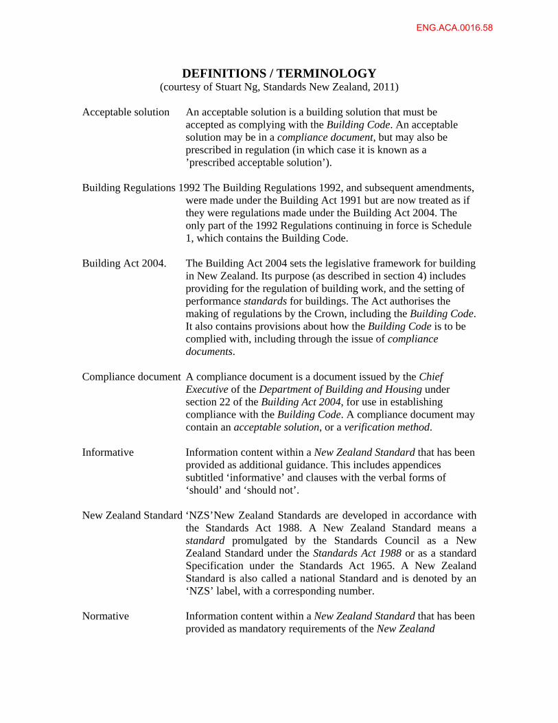
DEFINITIONS / TERMINOLOGY (courtesy of Stuart Ng, Standards New Zealand, 2011)
Acceptable solution An acceptable solution is a building solution that must be
accepted as complying with the Building Code. An acceptable solution may be in a compliance document, but may also be prescribed in regulation (in which case it is known as a ’prescribed acceptable solution’).
Building Regulations 1992 The Building Regulations 1992, and subsequent amendments,
were made under the Building Act 1991 but are now treated as if they were regulations made under the Building Act 2004. The only part of the 1992 Regulations continuing in force is Schedule 1, which contains the Building Code.
Building Act 2004. The Building Act 2004 sets the legislative framework for building
in New Zealand. Its purpose (as described in section 4) includes providing for the regulation of building work, and the setting of performance standards for buildings. The Act authorises the making of regulations by the Crown, including the Building Code. It also contains provisions about how the Building Code is to be complied with, including through the issue of compliance documents.
Compliance document A compliance document is a document issued by the Chief
Executive of the Department of Building and Housing under section 22 of the Building Act 2004, for use in establishing compliance with the Building Code. A compliance document may contain an acceptable solution, or a verification method.
Informative Information content within a New Zealand Standard that has been
provided as additional guidance. This includes appendices subtitled ‘informative’ and clauses with the verbal forms of ‘should’ and ‘should not’.
New Zealand Standard ‘NZS’ New Zealand Standards are developed in accordance with
the Standards Act 1988. A New Zealand Standard means a standard promulgated by the Standards Council as a New Zealand Standard under the Standards Act 1988 or as a standard Specification under the Standards Act 1965. A New Zealand Standard is also called a national Standard and is denoted by an ‘NZS’ label, with a corresponding number.
Normative Information content within a New Zealand Standard that has been
provided as mandatory requirements of the New Zealand
ENG.ACA.0016.58
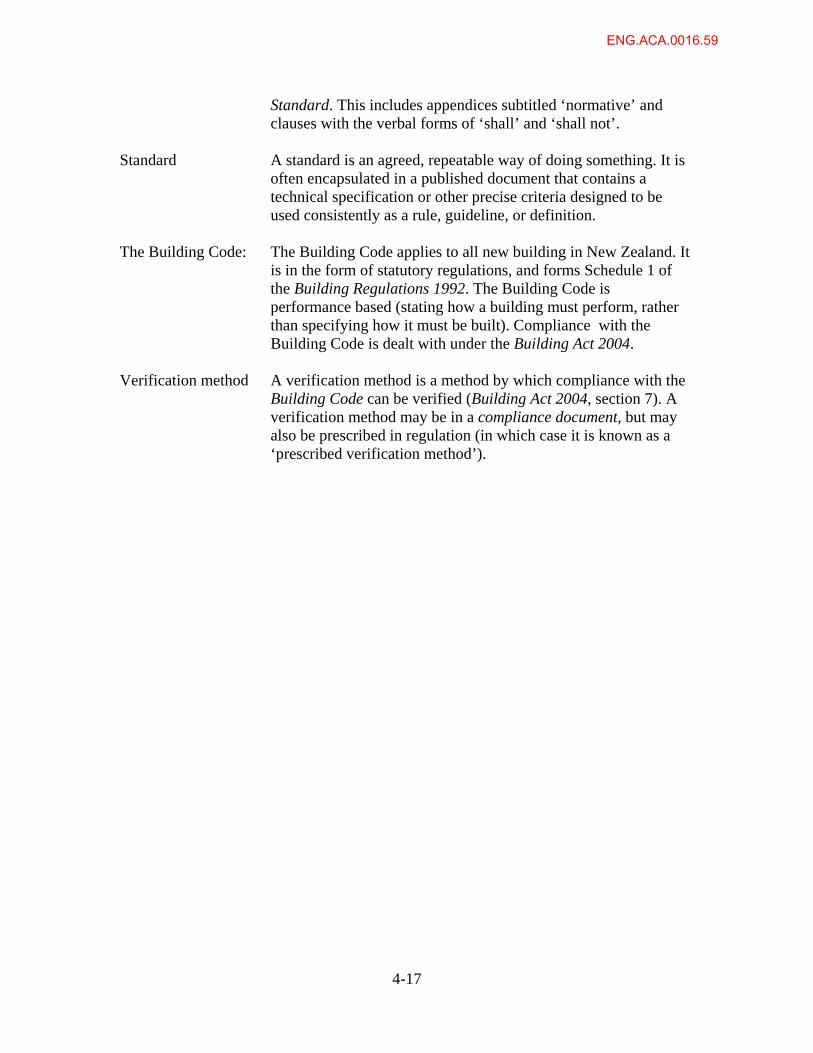
4-17
Standard. This includes appendices subtitled ‘normative’ and clauses with the verbal forms of ‘shall’ and ‘shall not’.
Standard A standard is an agreed, repeatable way of doing something. It is
often encapsulated in a published document that contains a technical specification or other precise criteria designed to be used consistently as a rule, guideline, or definition.
The Building Code: The Building Code applies to all new building in New Zealand. It
is in the form of statutory regulations, and forms Schedule 1 of the Building Regulations 1992. The Building Code is performance based (stating how a building must perform, rather than specifying how it must be built). Compliance with the Building Code is dealt with under the Building Act 2004.
Verification method A verification method is a method by which compliance with the
Building Code can be verified (Building Act 2004, section 7). A verification method may be in a compliance document, but may also be prescribed in regulation (in which case it is known as a ‘prescribed verification method’).
ENG.ACA.0016.59