Embed Size (px)
Citation preview
Paper Number O47
Design of base-isolated buildings: An overview of international codes
2014 NZSEE Conference
D. Pietra
Opus International Consultants Ltd, Auckland, New Zealand
S. Pampanin
Department of Civil Engineering, University of Canterbury, Christchurch, New Zealand
R.L. Mayes & N.G. Wetzel
Simpson Gumperz & Heger, California, United States of America
D. Feng
Fujita Corporation, Tokyo, Japan
ABSTRACT: Base isolation is arguably the most reliable method for providing enhanced
protection of buildings against earthquake-induced actions, by virtue of a physical separation
between the structure and the ground through elements with limited force capacity and (often)
enhanced energy dissipation. Such a design solution has shown its effectiveness in protecting
both the structural and non-structural components, hence preserving their functionality even in
the aftermath of a major seismic event.
Despite lead rubber bearings being invented in New Zealand almost forty years ago, the
Christchurch Women’s hospital was the only isolated building in Christchurch when the
Canterbury earthquakes occurred in 2010/11. Furthermore, a reference code for designing base-
isolated buildings in New Zealand is still missing. The absence of a design standard or at least
consensus on design guidelines is a potential source for a lack of uniformity in terms of
performance criteria and compliance design approaches. It may also limit more widespread use
of the technology in New Zealand.
The present paper provides an overview of the major international codes (American, Japanese
and European) for the design of base-isolated buildings. The design performance requirements,
the analysis procedures, the design review process and approval/quality control of devices
outlined in each code are discussed and their respective pros and cons are compared through a
design application on a benchmark building in New Zealand. The results gathered from this
comparison are intended to set the basis for the development of guidelines specific for the New
Zealand environment.
1 INTRODUCTION
The primary objective of the paper is to provide an overview of the major international codes for
designing base-isolated buildings, following the example of previous studies performed in Japan (as
summarised amongst all in Feng at al., 2006), in order to compare their respective provisions and
assess their potential for implementation in New Zealand. The focus is on design procedures, code
requirements and structural performance criteria. The three codes addressed in this paper are the
Japanese (Building Standard Law), the American (ASCE 7-10) and the European (Eurocode 8, EC8)
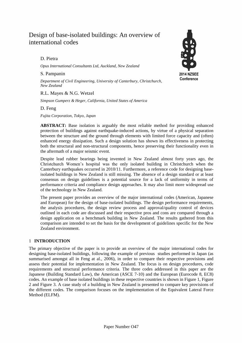
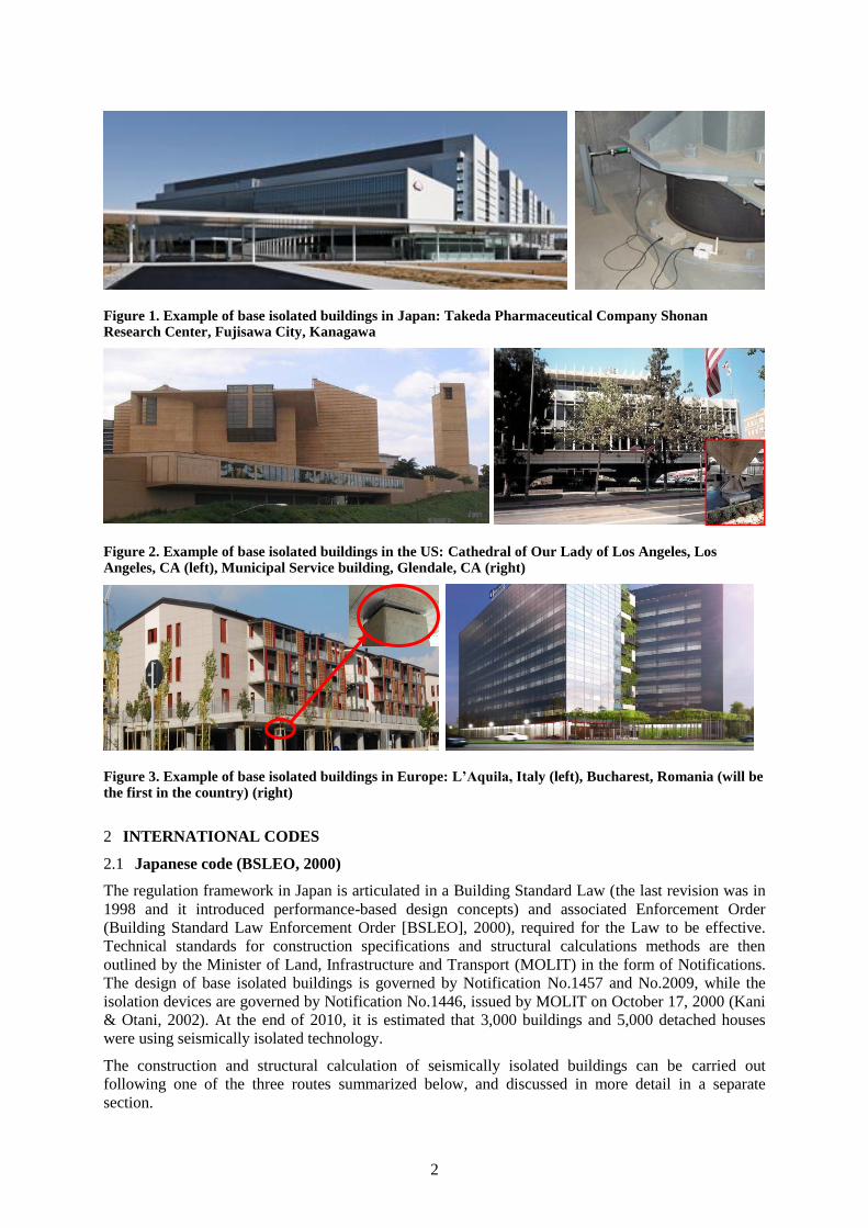
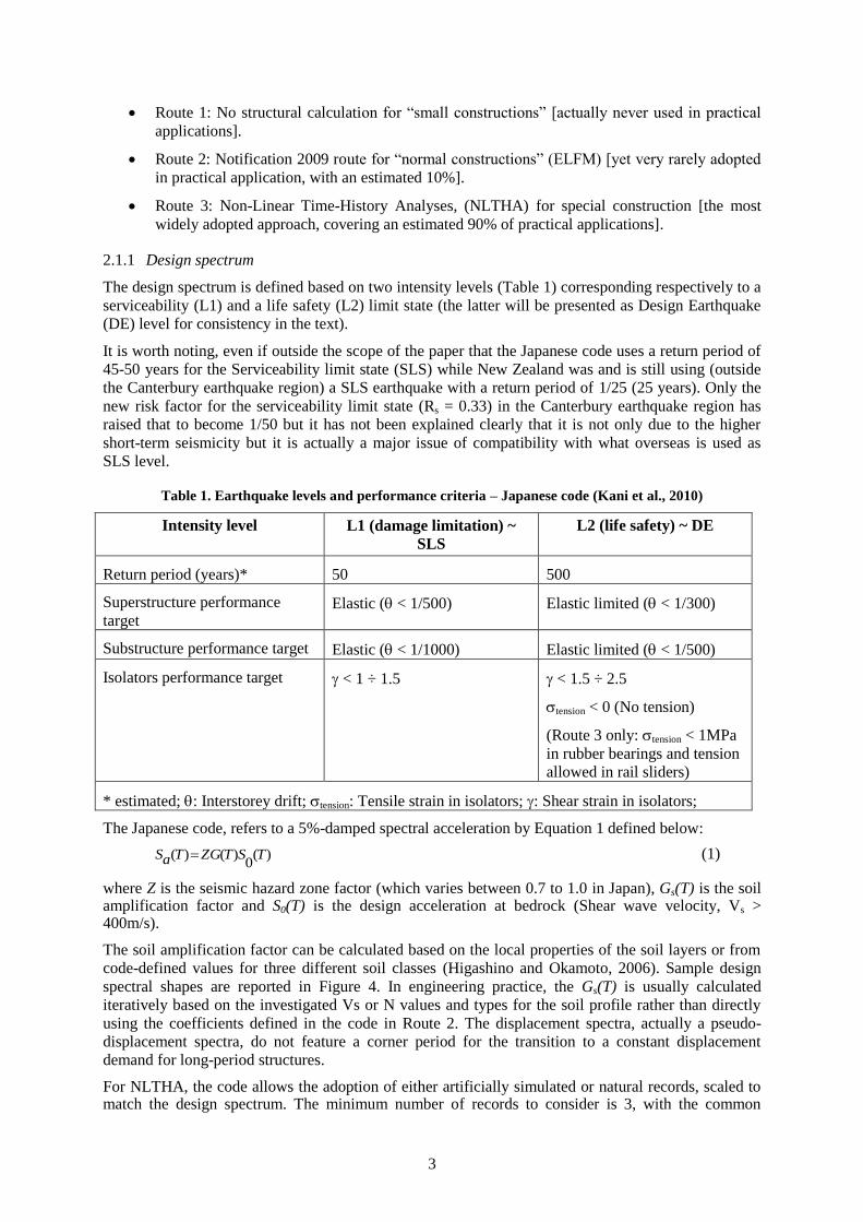
codes. An example of base isolated buildings in these respective countries is shown in Figure 1, Figure
2 and Figure 3. A case study of a building in New Zealand is presented to compare key provisions of
the different codes. The comparison focuses on the implementation of the Equivalent Lateral Force
Method (ELFM).
2
Figure 1. Example of base isolated buildings in Japan: Takeda Pharmaceutical Company Shonan Research Center, Fujisawa City, Kanagawa
Figure 2. Example of base isolated buildings in the US: Cathedral of Our Lady of Los Angeles, Los Angeles, CA (left), Municipal Service building, Glendale, CA (right)
Figure 3. Example of base isolated buildings in Europe: L’Aquila, Italy (left), Bucharest, Romania (will be the first in the country) (right)
2 INTERNATIONAL CODES
2.1 Japanese code (BSLEO, 2000)
The regulation framework in Japan is articulated in a Building Standard Law (the last revision was in
1998 and it introduced performance-based design concepts) and associated Enforcement Order
(Building Standard Law Enforcement Order [BSLEO], 2000), required for the Law to be effective.
Technical standards for construction specifications and structural calculations methods are then
outlined by the Minister of Land, Infrastructure and Transport (MOLIT) in the form of Notifications.
The design of base isolated buildings is governed by Notification No.1457 and No.2009, while the
isolation devices are governed by Notification No.1446, issued by MOLIT on October 17, 2000 (Kani
& Otani, 2002). At the end of 2010, it is estimated that 3,000 buildings and 5,000 detached houses
were using seismically isolated technology.
The construction and structural calculation of seismically isolated buildings can be carried out
following one of the three routes summarized below, and discussed in more detail in a separate
section.
3
Route 1: No structural calculation for “small constructions” [actually never used in practical
applications].
Route 2: Notification 2009 route for “normal constructions” (ELFM) [yet very rarely adopted
in practical application, with an estimated 10%].
Route 3: Non-Linear Time-History Analyses, (NLTHA) for special construction [the most
widely adopted approach, covering an estimated 90% of practical applications].
2.1.1 Design spectrum
The design spectrum is defined based on two intensity levels (Table 1) corresponding respectively to a
serviceability (L1) and a life safety (L2) limit state (the latter will be presented as Design Earthquake
(DE) level for consistency in the text).
It is worth noting, even if outside the scope of the paper that the Japanese code uses a return period of
45-50 years for the Serviceability limit state (SLS) while New Zealand was and is still using (outside
the Canterbury earthquake region) a SLS earthquake with a return period of 1/25 (25 years). Only the
new risk factor for the serviceability limit state (Rs = 0.33) in the Canterbury earthquake region has
raised that to become 1/50 but it has not been explained clearly that it is not only due to the higher
short-term seismicity but it is actually a major issue of compatibility with what overseas is used as
SLS level.
Table 1. Earthquake levels and performance criteria – Japanese code (Kani et al., 2010)
Intensity level L1 (damage limitation) ~
SLS
L2 (life safety) ~ DE
Return period (years)* 50 500
Superstructure performance
target Elastic ( < 1/500) Elastic limited ( < 1/300)
Substructure performance target Elastic ( < 1/1000) Elastic limited ( < 1/500)
Isolators performance target < 1 ÷ 1.5
< 1.5 ÷ 2.5
tension < 0 (No tension)
(Route 3 only:tension < 1MPa
in rubber bearings and tension
allowed in rail sliders)
* estimated; : Interstorey drift;tension: Tensile strain in isolators; : Shear strain in isolators;
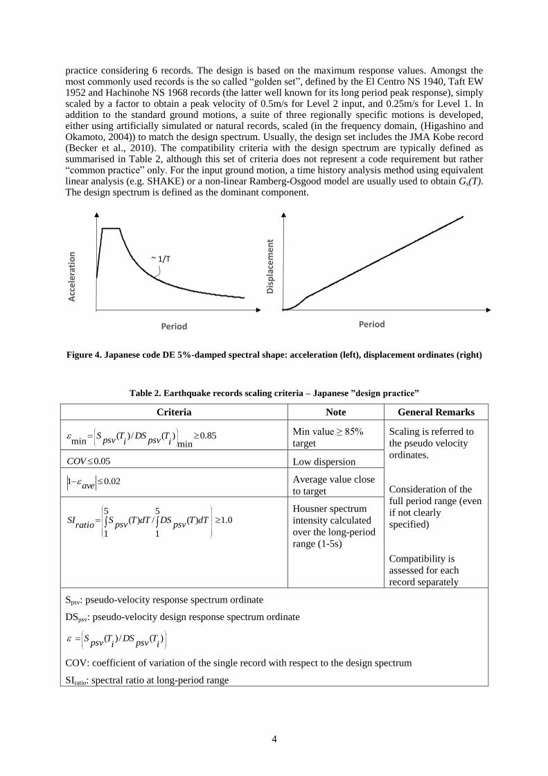
The Japanese code, refers to a 5%-damped spectral acceleration by Equation 1 defined below:
)(0
)()( TSTZGTaS (1)
where Z is the seismic hazard zone factor (which varies between 0.7 to 1.0 in Japan), Gs(T) is the soil amplification factor and S0(T) is the design acceleration at bedrock (Shear wave velocity, Vs > 400m/s).
The soil amplification factor can be calculated based on the local properties of the soil layers or from
code-defined values for three different soil classes (Higashino and Okamoto, 2006). Sample design
spectral shapes are reported in Figure 4. In engineering practice, the Gs(T) is usually calculated
iteratively based on the investigated Vs or N values and types for the soil profile rather than directly
using the coefficients defined in the code in Route 2. The displacement spectra, actually a pseudo-
displacement spectra, do not feature a corner period for the transition to a constant displacement
demand for long-period structures.
For NLTHA, the code allows the adoption of either artificially simulated or natural records, scaled to match the design spectrum. The minimum number of records to consider is 3, with the common
4
practice considering 6 records. The design is based on the maximum response values. Amongst the most commonly used records is the so called “golden set”, defined by the El Centro NS 1940, Taft EW 1952 and Hachinohe NS 1968 records (the latter well known for its long period peak response), simply scaled by a factor to obtain a peak velocity of 0.5m/s for Level 2 input, and 0.25m/s for Level 1. In addition to the standard ground motions, a suite of three regionally specific motions is developed, either using artificially simulated or natural records, scaled (in the frequency domain, (Higashino and Okamoto, 2004)) to match the design spectrum. Usually, the design set includes the JMA Kobe record (Becker et al., 2010). The compatibility criteria with the design spectrum are typically defined as summarised in Table 2, although this set of criteria does not represent a code requirement but rather “common practice” only. For the input ground motion, a time history analysis method using equivalent linear analysis (e.g. SHAKE) or a non-linear Ramberg-Osgood model are usually used to obtain Gs(T). The design spectrum is defined as the dominant component.
Figure 4. Japanese code DE 5%-damped spectral shape: acceleration (left), displacement ordinates (right)
Table 2. Earthquake records scaling criteria – Japanese ”design practice”
Criteria Note General Remarks
85.0min
)(/)(min
iT
psvDS
iT
psvS Min value ≥ 85%
target
Scaling is referred to
the pseudo velocity
ordinates.
Consideration of the
full period range (even
if not clearly
specified)
Compatibility is
assessed for each
record separately
05.0COV Low dispersion
02.01 ave Average value close
to target
0.15
1
)(/5
1
)(
dTTpsv
DSdTTpsv
Sratio
SI Housner spectrum
intensity calculated
over the long-period
range (1-5s)
Spsv: pseudo-velocity response spectrum ordinate
DSpsv: pseudo-velocity design response spectrum ordinate
)(/)(i
Tpsv
DSi
Tpsv
S
COV: coefficient of variation of the single record with respect to the design spectrum
SIratio: spectral ratio at long-period range
Acc
eler
atio
n
Period
Dis
pla
cem
ent
Period
~ 1/T
5
The design code in Japan does not include any importance factor (IF) for essential/critical facilities or
buildings where people are likely to congregate. However, it is common practice for local authorities
to require an importance factor to be adopted in practical applications. Typical values are 1.25 for
public buildings like schools and 1.5 for essential facilities, like for example hospitals. Such IFs
amplify the design spectrum, hence effectively requiring the design for a larger return period event, in
order to achieve higher performance in buildings with IF larger than 1.0 when compared to normal
class building for the same earthquake intensity.
2.1.2 Design method
Route 1: No structural calculation required. This route is meant to be available only for “small
constructions” (as defined in Table 3) and the design can be developed satisfying a set of boundaries
(Table 4), but without any calculation. This design pattern is presented here for completeness,
however, based on the authors’ experience, there is no evidence of any real implementation of this
approach in Japan.
Table 3. Definition of “small constructions” – Japanese code
Scenario Requirement
1 total floor area ≤ 100 m2
2 Timber construction not more than two stories
or not more than 500 m2 total floor area and not
more than 13 m in height
3 Buildings, other than timber
construction
single-story or of total floor area not more than 200
m2
6
Table 4. Requirements for the application of design Route 1 – Japanese code
Parameter Requirement Comments
[total floor area x
storey] / [# isolators]
≤ 15 m2 To provide redundancy and
redistribution of vertical
loads
[total yield strength
of the isolation
system (Fy) of
isolators] / [BLD
floor area (1 level)]
0.22 ÷ 0.36 Lightweight
buildings (1 storey)
Min: to ensure stability
under non-seismic loading.
Max: to limit the shear
demand in the building.
Building weight: allow for
larger shear forces to force
the adoption of units with
adequate stiffness to ensure
stability.
0.29 ÷ 0.49 Lightweight
buildings (2 storeys)
0.34 ÷ 0.58 Other buildings
[total strength of the
isolation system at
the design
displacement (Fd) of
isolators] / [BLD
floor area (1 level)]
0.72 ÷ 1.09 Lightweight
buildings (1 storey)
0.98 ÷ 1.47 Lightweight
buildings (2 storeys)
1.17 ÷ 1.75 Other buildings
Displacement
capacity of isolators
≥ 350mm
Equivalent damping
at design
displacement
≥ 20%
Ensure appropriate
load transfer from
the superstructure
Locate isolators at
the base of
columns/walls
Minimum tangent
period
2.5s (2.0s for
building height <
13m)
Isolated period referred to
the stiffness at the design
displacement level (Kani &
Otani, 2002)
Axial force on
isolators
No tensile forces Account for 0.3g up/down
static vertical seismic
acceleration (Kani et al.,
2010)
Maximum mass-
stiffness eccentricity
3%
Route 2: Notification 2009 route for normal constructions. Under this path, the building can be de-
signed on the basis of a 2D linear equivalent static analysis, subjected to the approval a building offi-
cial. The code defines as “normal constructions”:
o Buildings of total height (H) not greater than 60m (approximately 15-20 storey build-
ings),
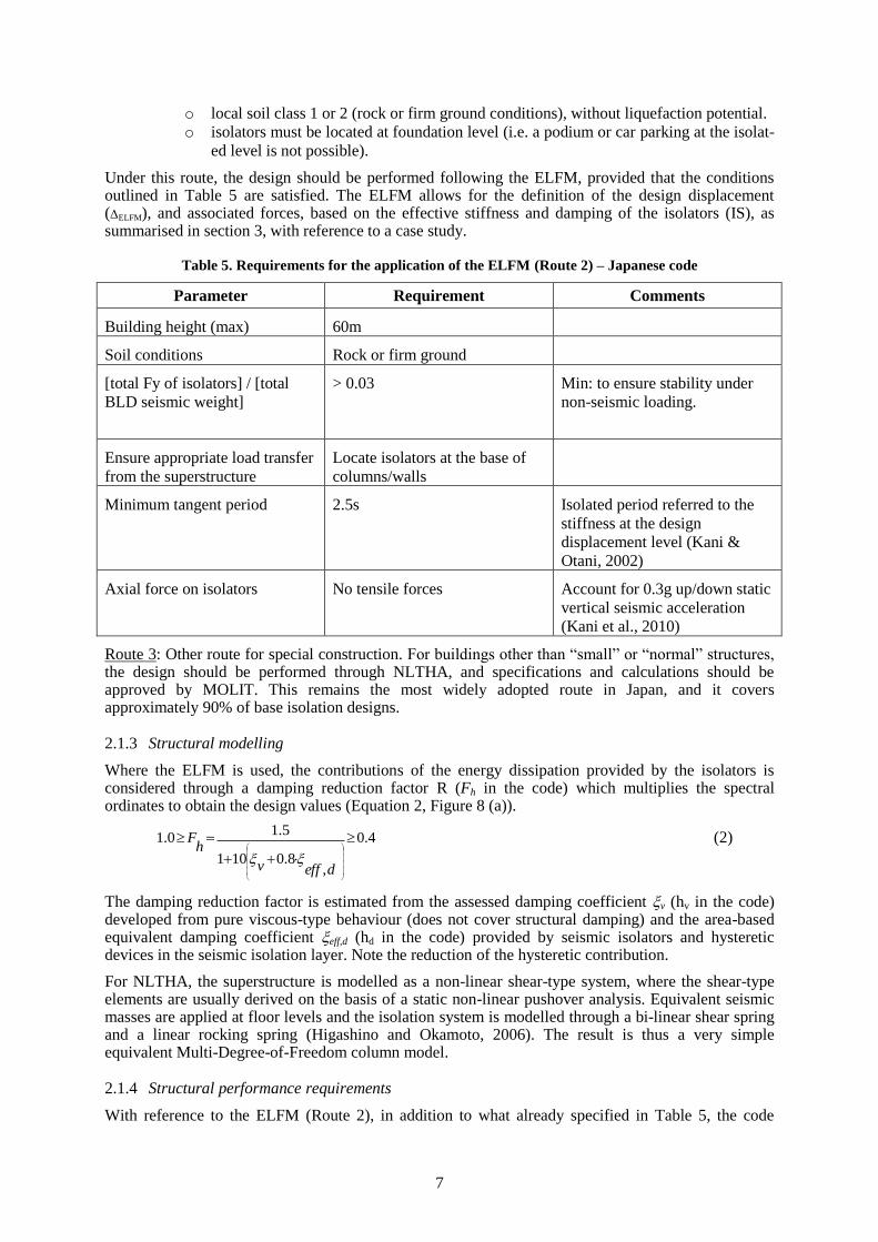
7
o local soil class 1 or 2 (rock or firm ground conditions), without liquefaction potential.
o isolators must be located at foundation level (i.e. a podium or car parking at the isolat-
ed level is not possible).
Under this route, the design should be performed following the ELFM, provided that the conditions outlined in Table 5 are satisfied. The ELFM allows for the definition of the design displacement (ELFM), and associated forces, based on the effective stiffness and damping of the isolators (IS), as summarised in section 3, with reference to a case study.
Table 5. Requirements for the application of the ELFM (Route 2) – Japanese code
Parameter Requirement Comments
Building height (max) 60m
Soil conditions Rock or firm ground
[total Fy of isolators] / [total
BLD seismic weight]
> 0.03 Min: to ensure stability under
non-seismic loading.
Ensure appropriate load transfer
from the superstructure
Locate isolators at the base of
columns/walls
Minimum tangent period 2.5s Isolated period referred to the
stiffness at the design
displacement level (Kani &
Otani, 2002)
Axial force on isolators No tensile forces Account for 0.3g up/down static
vertical seismic acceleration
(Kani et al., 2010)
Route 3: Other route for special construction. For buildings other than “small” or “normal” structures, the design should be performed through NLTHA, and specifications and calculations should be approved by MOLIT. This remains the most widely adopted route in Japan, and it covers approximately 90% of base isolation designs.
2.1.3 Structural modelling
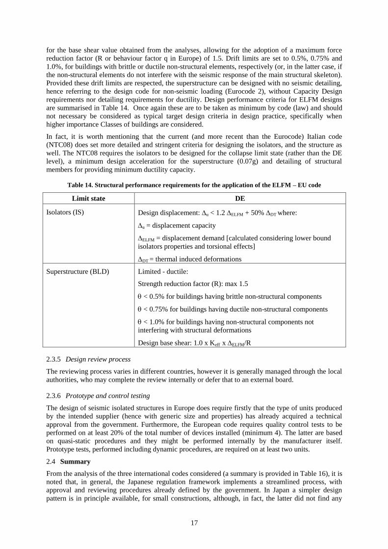
Where the ELFM is used, the contributions of the energy dissipation provided by the isolators is considered through a damping reduction factor R (Fh in the code) which multiplies the spectral ordinates to obtain the design values (Equation 2, Figure 8 (a)).
4.0
,8.0101
5.10.1
deffv
hF
(2)
The damping reduction factor is estimated from the assessed damping coefficient v (hv in the code) developed from pure viscous-type behaviour (does not cover structural damping) and the area-based equivalent damping coefficient eff,d (hd in the code) provided by seismic isolators and hysteretic devices in the seismic isolation layer. Note the reduction of the hysteretic contribution.
For NLTHA, the superstructure is modelled as a non-linear shear-type system, where the shear-type elements are usually derived on the basis of a static non-linear pushover analysis. Equivalent seismic masses are applied at floor levels and the isolation system is modelled through a bi-linear shear spring and a linear rocking spring (Higashino and Okamoto, 2006). The result is thus a very simple equivalent Multi-Degree-of-Freedom column model.
2.1.4 Structural performance requirements
With reference to the ELFM (Route 2), in addition to what already specified in Table 5, the code
8
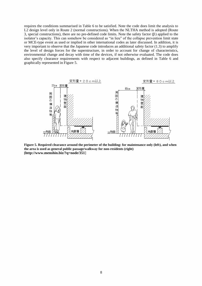
requires the conditions summarised in Table 6 to be satisfied. Note the code does limit the analysis to L2 design level only in Route 2 (normal constructions). When the NLTHA method is adopted (Route 3, special constructions), there are no pre-defined code limits. Note the safety factor () applied to the isolator’s capacity. This can somehow be considered as “in lieu” of the collapse prevention limit state or MCE-type event as used or implied in other international codes as later discussed. In addition, it is very important to observe that the Japanese code introduces an additional safety factor (1.3) to amplify the level of design forces for the superstructure, in order to account for change of characteristics, environmental change and decay with time of the devices, if not otherwise evaluated. The code does also specify clearance requirements with respect to adjacent buildings, as defined in Table 6 and graphically represented in Figure 5.
Figure 5. Required clearance around the perimeter of the building: for maintenance only (left), and when
the area is used as general public passage/walkway for non-residents (right)
[http://www.menshin.biz/?q=node/351]
9
Table 6. Structural performance requirements for the application of the ELFM – Japanese code
Limit state L2
Isolators (IS) < 1.5 ÷ 2.5
design shear strain in elastomeric bearings
Design displacement: d < u where:
d = 1.1 x 1.2 x ELFM [1.1: for torsion / 1.2 to account for environmental effects
and dispersion in properties]
safety factor (elastic Isolation Device (ID) = 0.8 – sliding/friction device = 0.9 –
Viscous Damper (VD) = 1)
u = displacement capacity
Design all connections for peak axial load & [1.2 x ELFM]
Clearance ≥ max of
* 1.25 d = 1.25 x 1.1 x 1.2 x ELFM
* 200mm + d = 200mm + 1.1 x 1.2 x ELFM
+ further 600mm if the area between buildings is used as the general public
passage/walkway (Figure 5)
Ensure possibility to replace/inspect ID
Provide maintenance plan
Provide fire protection: the cover should remain in place up to the design
displacement level
A sign must be posted at the location to allow visitors to observe that the building
implements Base Isolation (BI)
Superstructure
(BLD)
Elastic limited:
< 1/200 – H<13m
< 1/300 – H≥13m
Design base shear:
1.3 x Keff x ELFM
Max stresses:
Within code limits for short-term loading
2.1.5 Design review process
The review process is standardized in Japan. Route 2 (normal constructions) is verified as per any
seismic-resisting building by local government. Route 3 (special constructions) is reviewed by a
government mandated committee, which may be even run by a private company. This results in
reduced time, and it takes in general one or two months (Becker et al., 2010). The permission of
MOLIT usually takes more than two months. So the Route 3 will take 3-4 months more time than
Route 2.
2.1.6 Prototype and control testing
In Japan each device manufacturing company has a catalogue of pre-approved devices. The devices go
through an accreditation process run by the government mandated committee following Notification
No.1446. Manufactures submit the data required for accreditation. All the isolation devices going into
10
the building (with the exception of rail sliders) are subjected to a 100% quality control tests. (Becker et
al., 2010).
2.2 US code (ASCE 7-10)
2.2.1 Design spectrum
The current ASCE 7-10 code implements a 2-level design approach in which the structural design
forces are designed to the DE event and the isolators and all structural elements below the isolators are
designed to the Maximum Considered Earthquake (MCE). The DE event is defined as two-thirds of
the MCE event (resulting in MCE being equal to 1.5 times the DE event). The MCE event is based off
a risk targeted ground motions. Loosely the MCE event is either an event with a 2% probability of
exceedance in 50% years (return period of approximately 2500 years) or for near source locations it is
defined by the 1.8 times the deterministic median design event spectra. The design spectrum is based
on the SRSS combinations of the horizontal components (or maximum rotated component, NEHRP,
2011). An IF of 1.0 is adopted for all base isolated buildings, regardless of their use. The reference
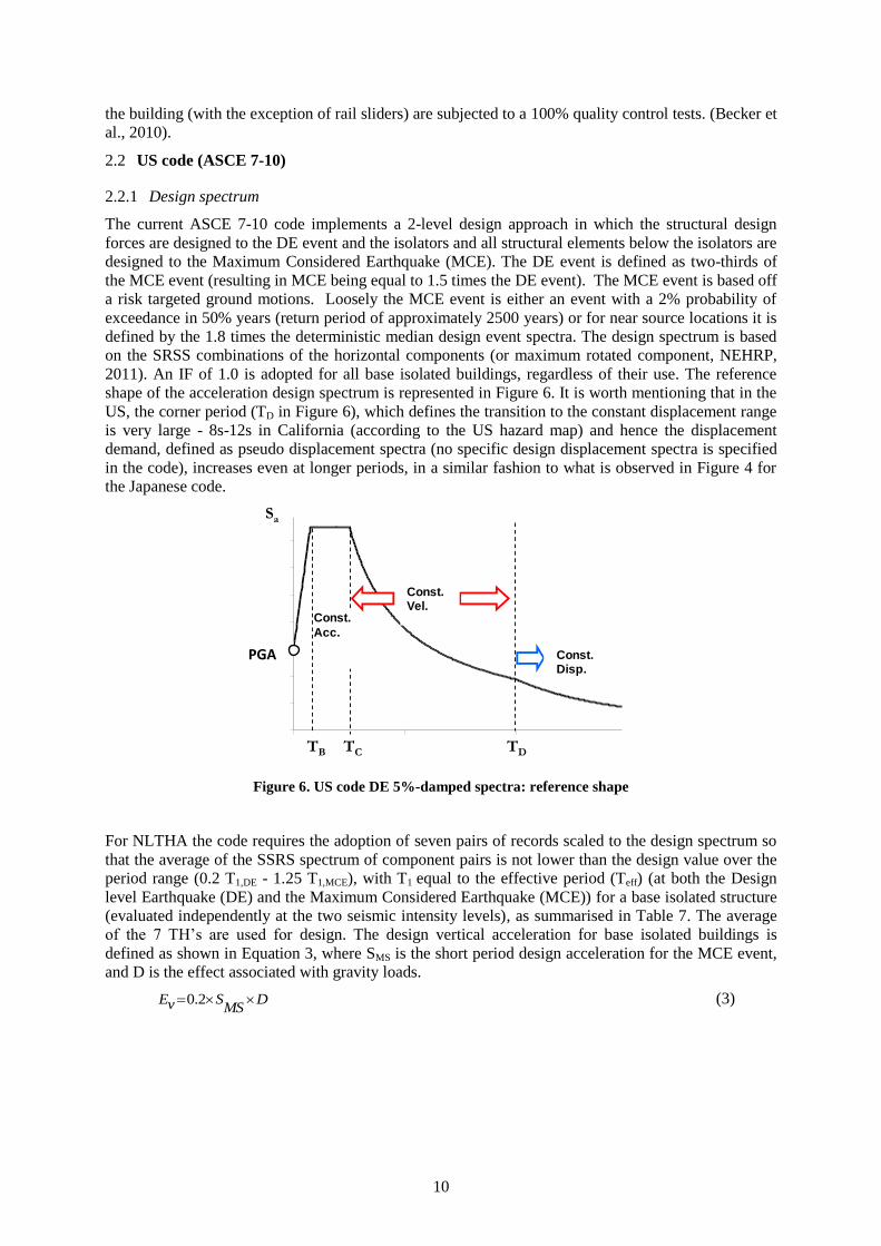
shape of the acceleration design spectrum is represented in Figure 6. It is worth mentioning that in the
US, the corner period (TD in Figure 6), which defines the transition to the constant displacement range
is very large - 8s-12s in California (according to the US hazard map) and hence the displacement
demand, defined as pseudo displacement spectra (no specific design displacement spectra is specified
in the code), increases even at longer periods, in a similar fashion to what is observed in Figure 4 for
the Japanese code.
Figure 6. US code DE 5%-damped spectra: reference shape
For NLTHA the code requires the adoption of seven pairs of records scaled to the design spectrum so
that the average of the SSRS spectrum of component pairs is not lower than the design value over the
period range (0.2 T1,DE - 1.25 T1,MCE), with T1 equal to the effective period (Teff) (at both the Design
level Earthquake (DE) and the Maximum Considered Earthquake (MCE)) for a base isolated structure
(evaluated independently at the two seismic intensity levels), as summarised in Table 7. The average
of the 7 TH’s are used for design. The design vertical acceleration for base isolated buildings is
defined as shown in Equation 3, where SMS is the short period design acceleration for the MCE event,
and D is the effect associated with gravity loads.
DMS
SvE 2.0 (3)
Periodo [s]
Accele
razio
ne [
g]
Acc.
Cost.
Vel.
Cost.
Spost.
Cost.
ag
0FSag
TB TC TD
Sa
Const.Vel.
Const.Disp.
Const.
Acc.
PGA
11
Table 7. Earthquake records scaling criteria – US code
Criteria Note General Remarks
dS
MCET
DET
iyS
ixS
pairsAverageSRSS
,1
25.1
,12.0
227
Calculate SRSS
spectrum for each
pair, and average
amongst 7-pairs.
The resultant of the
two components is
compared against the
design value.
Six: spectra for the x-component of record pair i
Siy: spectra for the y-component of record pair i
Sd: design spectrum
2.2.2 Design method
ASCE 7-10, allows the adoption of an equivalent linear analysis, or ELFM (the procedure is
summarised in section 3, Table 16), a Response Spectrum Analysis (RSA) or NLTHAs. Limitations
on the adoption of the ELFM apply both on the structural layout and seismicity of the site (Table 8), as
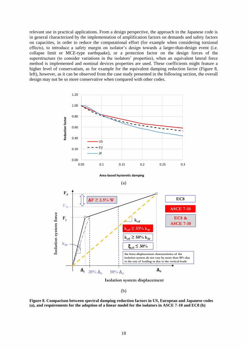
well as on the isolator properties (Figure 8 (b)).
Table 8. Requirements for the application of the ELFM – US code
Parameter Requirement Comments
Maximum effective
period
3.0s To allow for an equivalent linear model to
be used
Axial force on isolators No tensile forces
Soil conditions Site Class A, B, C, or D Not allowed for soft clay sites
Seismic intensity level Sd(1s) < 0.60g Not allowed in high seismicity areas
Superstructure Regular
Max 4 stories or 19.8m height
Isolators Equivalent Linear modelling
(Figure 8 (b))
2.2.3 Structural modelling
In linear analysis procedures the behaviour of the isolation system is represented by means of
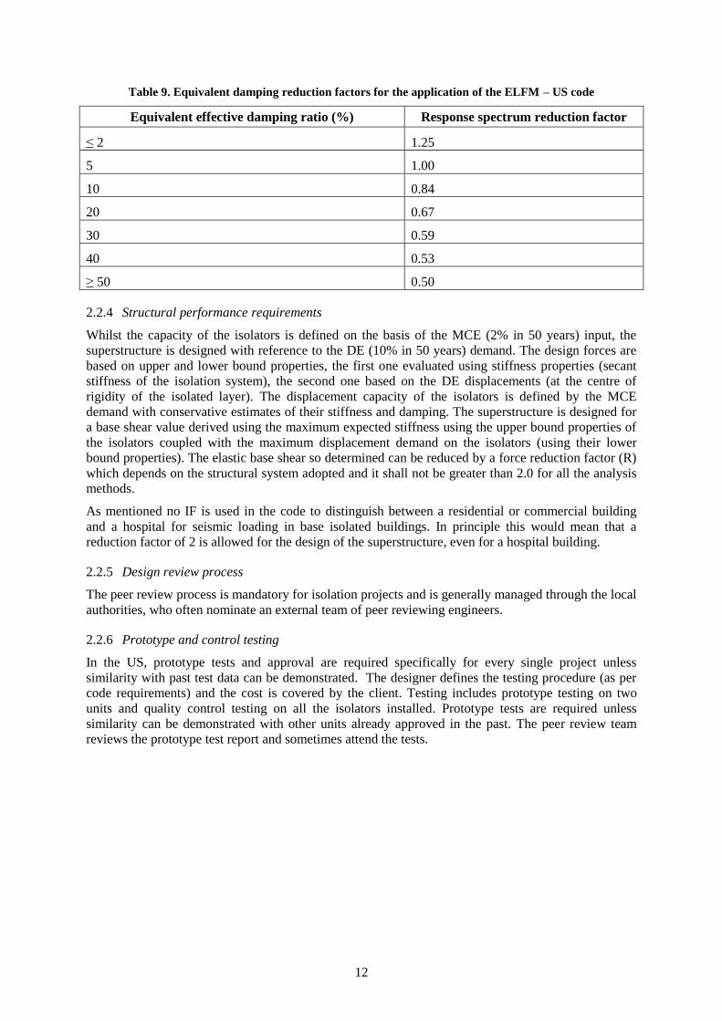
equivalent properties (stiffness and damping). The response spectrum reduction factor is defined in the
form of tabulated values corresponding to different levels of the equivalent damping s, as summarised
in Table 9 and Figure 8 (a). A full 3D model is used in RSAs, with full representation of bi-directional
loading and torsional response. The same applies to NLTHAs. Requirements apply for the adoption of
a linear model of the isolators (Figure 8 (b)) and variations in properties of the isolation system should
be evaluated by the engineer, based on long term environmental effects and prototype test results, as
well as lower and upper bound design scenarios.
12
Table 9. Equivalent damping reduction factors for the application of the ELFM – US code
Equivalent effective damping ratio (%) Response spectrum reduction factor
≤ 2 1.25
5 1.00
10 0.84
20 0.67
30 0.59
40 0.53
≥ 50 0.50
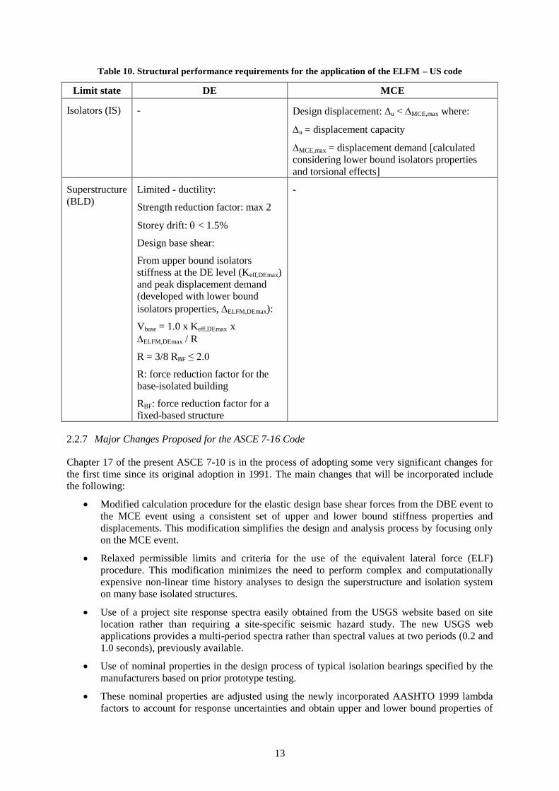
2.2.4 Structural performance requirements
Whilst the capacity of the isolators is defined on the basis of the MCE (2% in 50 years) input, the
superstructure is designed with reference to the DE (10% in 50 years) demand. The design forces are
based on upper and lower bound properties, the first one evaluated using stiffness properties (secant
stiffness of the isolation system), the second one based on the DE displacements (at the centre of
rigidity of the isolated layer). The displacement capacity of the isolators is defined by the MCE
demand with conservative estimates of their stiffness and damping. The superstructure is designed for
a base shear value derived using the maximum expected stiffness using the upper bound properties of
the isolators coupled with the maximum displacement demand on the isolators (using their lower
bound properties). The elastic base shear so determined can be reduced by a force reduction factor (R)
which depends on the structural system adopted and it shall not be greater than 2.0 for all the analysis
methods.
As mentioned no IF is used in the code to distinguish between a residential or commercial building
and a hospital for seismic loading in base isolated buildings. In principle this would mean that a
reduction factor of 2 is allowed for the design of the superstructure, even for a hospital building.
2.2.5 Design review process
The peer review process is mandatory for isolation projects and is generally managed through the local
authorities, who often nominate an external team of peer reviewing engineers.
2.2.6 Prototype and control testing
In the US, prototype tests and approval are required specifically for every single project unless
similarity with past test data can be demonstrated. The designer defines the testing procedure (as per
code requirements) and the cost is covered by the client. Testing includes prototype testing on two
units and quality control testing on all the isolators installed. Prototype tests are required unless
similarity can be demonstrated with other units already approved in the past. The peer review team
reviews the prototype test report and sometimes attend the tests.
13
Table 10. Structural performance requirements for the application of the ELFM – US code
Limit state DE MCE
Isolators (IS) - Design displacement: u < MCE,max where:
u = displacement capacity
MCE,max = displacement demand [calculated
considering lower bound isolators properties
and torsional effects]
Superstructure
(BLD)
Limited - ductility:
Strength reduction factor: max 2
Storey drift: < 1.5%
Design base shear:
From upper bound isolators
stiffness at the DE level (Keff,DEmax)
and peak displacement demand
(developed with lower bound
isolators properties, ELFM,DEmax):
Vbase = 1.0 x Keff,DEmax x
ELFM,DEmax / R
R = 3/8 RBF ≤ 2.0
R: force reduction factor for the
base-isolated building
RBF: force reduction factor for a
fixed-based structure
-
2.2.7 Major Changes Proposed for the ASCE 7-16 Code
Chapter 17 of the present ASCE 7-10 is in the process of adopting some very significant changes for
the first time since its original adoption in 1991. The main changes that will be incorporated include
the following:
Modified calculation procedure for the elastic design base shear forces from the DBE event to
the MCE event using a consistent set of upper and lower bound stiffness properties and
displacements. This modification simplifies the design and analysis process by focusing only
on the MCE event.
Relaxed permissible limits and criteria for the use of the equivalent lateral force (ELF)
procedure. This modification minimizes the need to perform complex and computationally
expensive non-linear time history analyses to design the superstructure and isolation system
on many base isolated structures.
Use of a project site response spectra easily obtained from the USGS website based on site
location rather than requiring a site-specific seismic hazard study. The new USGS web
applications provides a multi-period spectra rather than spectral values at two periods (0.2 and
1.0 seconds), previously available.
Use of nominal properties in the design process of typical isolation bearings specified by the
manufacturers based on prior prototype testing.
These nominal properties are adjusted using the newly incorporated AASHTO 1999 lambda
factors to account for response uncertainties and obtain upper and lower bound properties of

14
the isolation system for the design process.
New method for the vertical distribution of lateral forces associated with the ELF method of
design. This revision incorporates a more accurate distribution of shear over height
considering the period of the superstructure and the effective damping of the isolation system
and it does not distribute the mass of the isolated base slab vertically as the current provisions
do.
Simplified approach for incorporating a 5% accidental mass eccentricity in non-linear time
history analyses.
Reduction in the required number of peer reviewers on a seismic isolation project from the
current panel of 3-5 working as a team to a minimum of one peer reviewer. Also, peer
reviewers are not required to attend the prototype tests.
Calculation procedure to estimate permanent residual displacements that may occur in seismic
isolation applications with relatively long period high yield/friction levels, and small yield
displacements under a wide range of earthquake intensity.
2.3 Europe (EC8)
2.3.1 Design spectrum
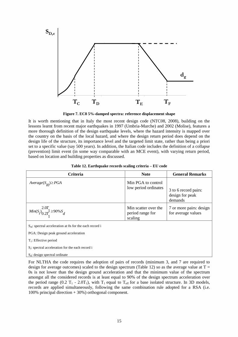
The design spectrum in EC8 is representative of a 500 years return period event, and it is defined with reference to the dominant earthquake component. Both the horizontal components are assumed to be applied simultaneously and in conjunction with the vertical ground acceleration. The code presents a specific design displacement spectrum, not simply derived from pseudo-displacement considerations, which features a corner period at 2s (i.e. the period when the constant displacement regime starts in the acceleration design spectrum) and starts decaying from TE (Figure 7) to the level of peak ground displacement for longer periods (TF onwards). Hence, even if the design spectral shape is similar to what shown in Figure 6 for ASCE 7-10, the constant displacement range starts much earlier (2s) and the displacement spectrum assumes the reference shape depicted in Figure 7.
Further, the code distinguishes between different importance levels for the structure, by introducing specific IFs, with 1.0 for Importance Class II (ordinary building) to 1.4 for Importance Class IV (critical facilities) (Table 11).
Table 11. Importance classes and Importance factors (recommended values) – EU code
Importance class Importance factor
I Buildings of minor importance for public safety, e.g.
agricultural
buildings, etc.
0.8
II Ordinary buildings, not belonging in the other categories. 1.0
III Buildings whose seismic resistance is of importance in view of
the
consequences associated with a collapse, e.g. schools, assembly
halls,
cultural institutions etc.
1.2
IV Buildings whose integrity during earthquakes is of vital
importance
for civil protection, e.g. hospitals, fire stations, power plants,
etc.
1.4
15
Figure 7. EC8 5%-damped spectra: reference displacement shape
It is worth mentioning that in Italy the most recent design code (NTC08, 2008), building on the
lessons learnt from recent major earthquakes in 1997 (Umbria-Marche) and 2002 (Molise), features a
more thorough definition of the design earthquake levels, where the hazard intensity is mapped over
the country on the basis of the local hazard, and where the design return period does depend on the
design life of the structure, its importance level and the targeted limit state, rather than being a priori
set to a specific value (say 500 years). In addition, the Italian code includes the definition of a collapse
(prevention) limit event (in some way comparable with an MCE event), with varying return period,
based on location and building properties as discussed.
Table 12. Earthquake records scaling criteria – EU code
Criteria Note General Remarks
PGAi
SAverage )0
( Min PGA to control
low period ordinates
3 to 6 record pairs:
design for peak
demands
dS
T
TiSMin %901
0.2
12.0
)( Min scatter over the
period range for
scaling
7 or more pairs: design
for average values
Si0: spectral acceleration at 0s for the each record i
PGA: Design peak ground acceleration
T1: Effective period
Si: spectral acceleration for the each record i
Sd: design spectral ordinate
For NLTHA the code requires the adoption of pairs of records (minimum 3, and 7 are required to
design for average outcomes) scaled to the design spectrum (Table 12) so as the average value at T =
0s is not lower than the design ground acceleration and that the minimum value of the spectrum
amongst all the considered records is at least equal to 90% of the design spectrum acceleration over
the period range (0.2 T1 - 2.0T1), with T1 equal to Teff for a base isolated structure. In 3D models,
records are applied simultaneously, following the same combination rule adopted for a RSA (i.e.
100% principal direction + 30%) orthogonal component.
Periodo [s]
Accele
razio
ne [
g]
TC TD TF
SD,e
TE
dg
2
0 DCg TTFSa
16
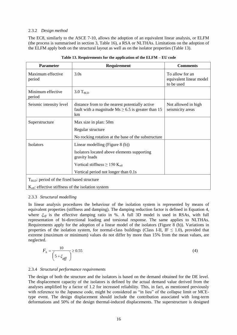
2.3.2 Design method
The EC8, similarly to the ASCE 7-10, allows the adoption of an equivalent linear analysis, or ELFM
(the process is summarised in section 3, Table 16), a RSA or NLTHAs. Limitations on the adoption of
the ELFM apply both on the structural layout as well as on the isolator properties (Table 13).
Table 13. Requirements for the application of the ELFM – EU code
Parameter Requirement Comments
Maximum effective
period
3.0s To allow for an
equivalent linear model
to be used
Minimum effective
period
3.0 TBLD
Seismic intensity level distance from to the nearest potentially active
fault with a magnitude Ms ≥ 6.5 is greater than 15
km
Not allowed in high
seismicity areas
Superstructure Max size in plan: 50m
Regular structure
No rocking rotation at the base of the substructure
Isolators Linear modelling (Figure 8 (b))
Isolators located above elements supporting
gravity loads
Vertical stiffness ≥ 150 Keff
Vertical period not longer than 0.1s
TBLD: period of the fixed based structure
Keff: effective stiffness of the isolation system
2.3.3 Structural modelling
In linear analysis procedures the behaviour of the isolation system is represented by means of
equivalent properties (stiffness and damping). The damping reduction factor is defined in Equation 4,
where eff is the effective damping ratio in %. A full 3D model is used in RSAs, with full
representation of bi-directional loading and torsional response. The same applies to NLTHAs.
Requirements apply for the adoption of a linear model of the isolators (Figure 8 (b)). Variations in
properties of the isolation system, for normal-class buildings (Class I-II, IF ≤ 1.0), provided that
extreme (maximum or minimum) values do not differ by more than 15% from the mean values, are
neglected.
55.0
5
10
eff
hF
(4)
2.3.4 Structural performance requirements
The design of both the structure and the isolators is based on the demand obtained for the DE level.
The displacement capacity of the isolators is defined by the actual demand value derived from the
analyses amplified by a factor of 1.2 for increased reliability. This, in fact, as mentioned previously
with reference to the Japanese code, might be considered as “in lieu” of the collapse limit or MCE-
type event. The design displacement should include the contribution associated with long-term
deformations and 50% of the design thermal-induced displacements. The superstructure is designed
17
for the base shear value obtained from the analyses, allowing for the adoption of a maximum force
reduction factor (R or behaviour factor q in Europe) of 1.5. Drift limits are set to 0.5%, 0.75% and
1.0%, for buildings with brittle or ductile non-structural elements, respectively (or, in the latter case, if
the non-structural elements do not interfere with the seismic response of the main structural skeleton).
Provided these drift limits are respected, the superstructure can be designed with no seismic detailing,
hence referring to the design code for non-seismic loading (Eurocode 2), without Capacity Design
requirements nor detailing requirements for ductility. Design performance criteria for ELFM designs
are summarised in Table 14. Once again these are to be taken as minimum by code (law) and should
not necessary be considered as typical target design criteria in design practice, specifically when
higher importance Classes of buildings are considered.
In fact, it is worth mentioning that the current (and more recent than the Eurocode) Italian code
(NTC08) does set more detailed and stringent criteria for designing the isolators, and the structure as
well. The NTC08 requires the isolators to be designed for the collapse limit state (rather than the DE
level), a minimum design acceleration for the superstructure (0.07g) and detailing of structural
members for providing minimum ductility capacity.
Table 14. Structural performance requirements for the application of the ELFM – EU code
Limit state DE
Isolators (IS) Design displacement: u < 1.2 ELFM + 50% DT where:
u = displacement capacity
ELFM = displacement demand [calculated considering lower bound
isolators properties and torsional effects]
DT = thermal induced deformations
Superstructure (BLD) Limited - ductile:
Strength reduction factor (R): max 1.5
< 0.5% for buildings having brittle non-structural components
< 0.75% for buildings having ductile non-structural components
< 1.0% for buildings having non-structural components not
interfering with structural deformations
Design base shear: 1.0 x Keff x ELFM/R
2.3.5 Design review process
The reviewing process varies in different countries, however it is generally managed through the local
authorities, who may complete the review internally or defer that to an external board.
2.3.6 Prototype and control testing
The design of seismic isolated structures in Europe does require firstly that the type of units produced
by the intended supplier (hence with generic size and properties) has already acquired a technical
approval from the government. Furthermore, the European code requires quality control tests to be
performed on at least 20% of the total number of devices installed (minimum 4). The latter are based
on quasi-static procedures and they might be performed internally by the manufacturer itself.
Prototype tests, performed including dynamic procedures, are required on at least two units.
2.4 Summary
From the analysis of the three international codes considered (a summary is provided in Table 16), it is
noted that, in general, the Japanese regulation framework implements a streamlined process, with
approval and reviewing procedures already defined by the government. In Japan a simpler design
pattern is in principle available, for small constructions, although, in fact, the latter did not find any
18
relevant use in practical applications. From a design perspective, the approach in the Japanese code is
in general characterized by the implementation of amplification factors on demands and safety factors
on capacities, in order to reduce the computational effort (for example when considering torsional
effects), to introduce a safety margin on isolator’s design towards a larger-than-design event (i.e.
collapse limit or MCE-type earthquake), or a protection factor on the design forces of the
superstructure (to consider variations in the isolators’ properties), when an equivalent lateral force
method is implemented and nominal devices properties are used. These coefficients might feature a
higher level of conservatism, as for example for the equivalent damping reduction factor (Figure 8,
left), however, as it can be observed from the case study presented in the following section, the overall
design may not be so more conservative when compared with other codes.
(a)
(b)
Figure 8. Comparison between spectral damping reduction factors in US, European and Japanese codes (a), and requirements for the adoption of a linear model for the isolators in ASCE 7-10 and EC8 (b)
0.00
0.20
0.40
0.60
0.80
1.00
1.20
0.05 0.1 0.15 0.2 0.25 0.3
Re
duct
ion
fact
or
Area-based hysteretic damping
Equivalent damping reduction factor
US
EU
JP
k20
Fd
y d
keff ≥ 50% k20
Fy
20% d
keff
eff ≤ 30%
the force-displacement characteristics of the
isolation system do not vary by more than 10% due
to the rate of loading or due to the vertical loads
F ≥ 2.5% W
F50
50% d
keff ≥ 33% k20
EC8
ASCE 7-10
EC8 &
ASCE 7-10
Isolation system displacement
Iso
lati
on
syst
em
fo
rce
19
The US code, by virtue of the MCE level adopted for designing the isolators, results in higher
demands on these units, while, on the other side, the code allows for a certain level of ductile
behaviour of the superstructure, hence with lower design forces, however requiring adequate structural
detailing for seismic loading. This distinguishes the US from the Japanese and the European codes,
where the design mainly focuses on DE levels and requires the superstructure to respond elastically.
Both the EU and Japanese codes also provide an amplification factor of 1.2 on the isolator
displacement demand, somehow building some redundancy (on the isolators) for a higher than DE
level earthquake.
More so, the Japanese code, introduces a unique amplification factor of 1.3 to the base shear, on the
basis of a capacity design approach, when forces are obtained from nominal isolators’ properties.
It is worth noting that the EC8 does not represent the most advanced European regulation. The recent
Italian Code (NTC08), for example, has been developed further and it introduces a collapse limit, or
MCE-type event, for designing the isolators, in parallel to a DE level for designing of the
superstructure. However, as ASCE 7-10 does, it includes stringent requirements for the adoption of a
linear procedure, hence limiting the selection of the isolators. Of major relevance are also the
differences in terms of definition of the equivalent lateral load pattern for designing the superstructure
(proportional to the storey mass only – not the height – in EC8), and the introduction of a structural
importance level coefficient (IF ≥ 1.0).
In general, it might be concluded that, with reference to normal or ordinary buildings (Importance
Factor, IF = 1), ASCE7-10 seems to provide a more conservative design of the isolators (in
considerations of the MCE displacement demand). The design forces compared in the case study
below are quite similar for the Euro and US codes. The US code requires the same ductile structural
detailing as a conventional structure. The EC8 and Japanese code seems to allow less non-ductile
structures to be used in conjunction with an isolation system.
Such conclusions change for a structure with an importance factor greater than 1.0. Whilst both
Japanese and European regulations see a significant increase in the key design parameters, an ASCE
7-10-based design does not have an importance factor. Thus the displacement demands are the same
for all building types and California hospitals are limited to an R-Factor of 1.5. The design criteria for
the isolators is also very different between the European and US codes on one side and the Japanese
code on the other side, with the latter allowing for much flexible systems, by virtue of setting a
minimum level for the tangent (isolated) period and by removing requirements on linear modelling of
the isolation system. This obviously may have implications on the reliability of the linear analysis
outcomes and on the control of the deformation demand during severe events.
Finally, it is worth recalling that the US and Japanese codes both, in practice, do not include a corner
period in the design spectrum (very large - 8s-12s in California - according to the US hazard map).
Other codes, such as EC8 or NZS 1170.5, implement a corner period, and hence a constant
displacement demand region. In general the definition of a constant displacement plateau seems to
depend on the local characteristics of the seismic hazard and it should be thus better calibrated on the
basis of a seismic hazard study for each specific region, and neglected if justified by the nature of the
ground acceleration records.
20
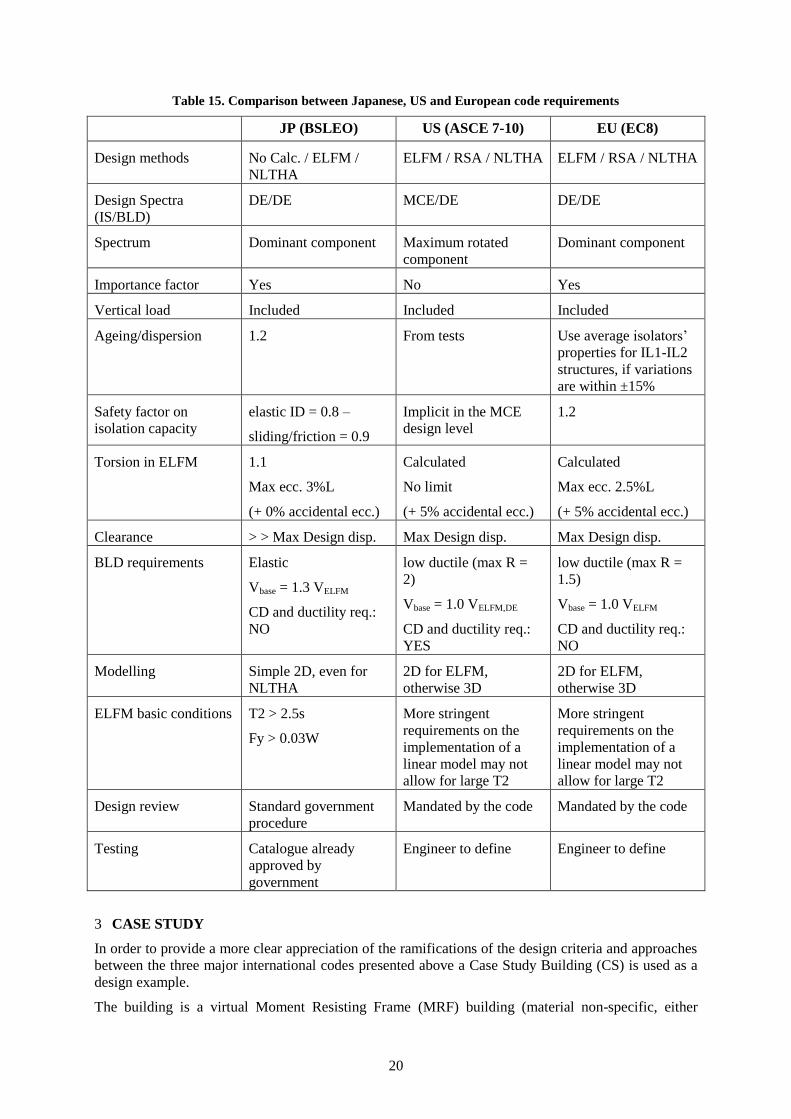
Table 15. Comparison between Japanese, US and European code requirements
JP (BSLEO) US (ASCE 7-10) EU (EC8)
Design methods No Calc. / ELFM /
NLTHA
ELFM / RSA / NLTHA ELFM / RSA / NLTHA
Design Spectra
(IS/BLD)
DE/DE MCE/DE DE/DE
Spectrum Dominant component Maximum rotated
component
Dominant component
Importance factor Yes No Yes
Vertical load Included Included Included
Ageing/dispersion 1.2 From tests Use average isolators’
properties for IL1-IL2
structures, if variations
are within ±15%
Safety factor on
isolation capacity
elastic ID = 0.8 –
sliding/friction = 0.9
Implicit in the MCE
design level
1.2
Torsion in ELFM 1.1
Max ecc. 3%L
(+ 0% accidental ecc.)
Calculated
No limit
(+ 5% accidental ecc.)
Calculated
Max ecc. 2.5%L
(+ 5% accidental ecc.)
Clearance > > Max Design disp. Max Design disp. Max Design disp.
BLD requirements Elastic
Vbase = 1.3 VELFM
CD and ductility req.:
NO
low ductile (max R =
2)
Vbase = 1.0 VELFM,DE
CD and ductility req.:
YES
low ductile (max R =
1.5)
Vbase = 1.0 VELFM
CD and ductility req.:
NO
Modelling Simple 2D, even for
NLTHA
2D for ELFM,
otherwise 3D
2D for ELFM,
otherwise 3D
ELFM basic conditions T2 > 2.5s
Fy > 0.03W
More stringent
requirements on the
implementation of a
linear model may not
allow for large T2
More stringent
requirements on the
implementation of a
linear model may not
allow for large T2
Design review Standard government
procedure
Mandated by the code Mandated by the code
Testing Catalogue already
approved by
government
Engineer to define Engineer to define
3 CASE STUDY
In order to provide a more clear appreciation of the ramifications of the design criteria and approaches
between the three major international codes presented above a Case Study Building (CS) is used as a
design example.
The building is a virtual Moment Resisting Frame (MRF) building (material non-specific, either
21
concrete, steel, timber or combination of the above) featuring three storeys and a total seismic weight
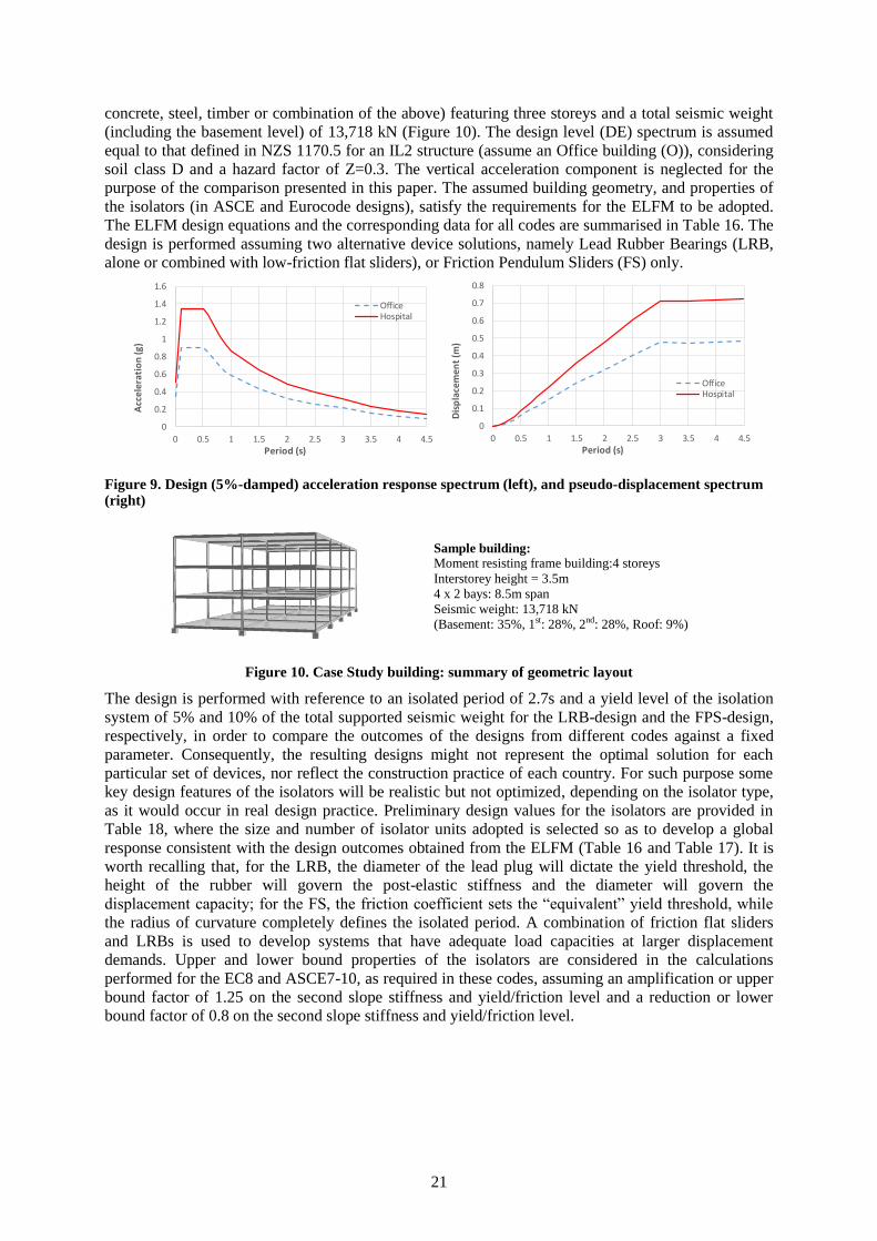
(including the basement level) of 13,718 kN (Figure 10). The design level (DE) spectrum is assumed
equal to that defined in NZS 1170.5 for an IL2 structure (assume an Office building (O)), considering
soil class D and a hazard factor of Z=0.3. The vertical acceleration component is neglected for the
purpose of the comparison presented in this paper. The assumed building geometry, and properties of
the isolators (in ASCE and Eurocode designs), satisfy the requirements for the ELFM to be adopted.
The ELFM design equations and the corresponding data for all codes are summarised in Table 16. The
design is performed assuming two alternative device solutions, namely Lead Rubber Bearings (LRB,
alone or combined with low-friction flat sliders), or Friction Pendulum Sliders (FS) only.
Figure 9. Design (5%-damped) acceleration response spectrum (left), and pseudo-displacement spectrum (right)
Sample building:
Moment resisting frame building:4 storeys
Interstorey height = 3.5m
4 x 2 bays: 8.5m span
Seismic weight: 13,718 kN
(Basement: 35%, 1st: 28%, 2nd: 28%, Roof: 9%)
Figure 10. Case Study building: summary of geometric layout
The design is performed with reference to an isolated period of 2.7s and a yield level of the isolation
system of 5% and 10% of the total supported seismic weight for the LRB-design and the FPS-design,
respectively, in order to compare the outcomes of the designs from different codes against a fixed
parameter. Consequently, the resulting designs might not represent the optimal solution for each
particular set of devices, nor reflect the construction practice of each country. For such purpose some
key design features of the isolators will be realistic but not optimized, depending on the isolator type,
as it would occur in real design practice. Preliminary design values for the isolators are provided in
Table 18, where the size and number of isolator units adopted is selected so as to develop a global
response consistent with the design outcomes obtained from the ELFM (Table 16 and Table 17). It is
worth recalling that, for the LRB, the diameter of the lead plug will dictate the yield threshold, the
height of the rubber will govern the post-elastic stiffness and the diameter will govern the
displacement capacity; for the FS, the friction coefficient sets the “equivalent” yield threshold, while
the radius of curvature completely defines the isolated period. A combination of friction flat sliders
and LRBs is used to develop systems that have adequate load capacities at larger displacement
demands. Upper and lower bound properties of the isolators are considered in the calculations
performed for the EC8 and ASCE7-10, as required in these codes, assuming an amplification or upper
bound factor of 1.25 on the second slope stiffness and yield/friction level and a reduction or lower
bound factor of 0.8 on the second slope stiffness and yield/friction level.
0
0.2
0.4
0.6
0.8
1
1.2
1.4
1.6
0 0.5 1 1.5 2 2.5 3 3.5 4 4.5
Acc
eler
atio
n (g
)
Period (s)
OfficeHospital
0
0.1
0.2
0.3
0.4
0.5
0.6
0.7
0.8
0 0.5 1 1.5 2 2.5 3 3.5 4 4.5
Dis
pla
cem
ent
(m)
Period (s)
OfficeHospital
22
Table 16. Case study: ELFM procedure: LRB design
Parameter JP (BSLEO) US (ASCE 7-10) EU (EC8)
Case Study
Office / Hospital
Case Study
Office / Hospital
Case Study
Office / Hospital
Tangent period,
T2 (s)
2.7 / 2.7 2.7 / 2.7 2.7 / 2.7
Isolator Yield
force ratio (Fy/W)
0.05 / 0.05 0.05 / 0.05 0.05 / 0.05
Centre of mass
displacement, CM
(mm)
226 / 506 582 / 582 318 / 526
Factor for torsion
(TF)
1.1 / 1.1 1.24 / 1.24 1.15 / 1.15
Safety factor on
device capacity,
0.8 / 0.8 1.0 / 1.0 1.2 / 1.2
Max design
displacement, d
(mm)
426 / 706 720 / 720 438 / 725
Total elastic base
shear (Vb,e/W)
0.18 / 0.33 0.31 / 0.31 0.18 / 0.32
Total design base
shear (Vb /W)
0.23 / 0.43 0.16 / 0.21 0.12 / 0.21
Furthermore, the outcomes, in terms of design base shear for the superstructure are based on the
assumption that the maximum force reduction factor (or ductility factor or reduction factor) allowed in
each respective code is used. For instance, the design for the Hospital-type building (H) according to
the ASCE 7-10 is performed under the assumption that a maximum R Factor of 1.5 is required by the
local authorities (OSHPD) in California (the same assumption is adopted here also for the EC8
design). The design is finally repeated assuming the same building will feature a higher importance
class (for example a Hospital, H), assuming an IF of 1.4 in European codes. The design spectra for the
“Office-type” building scenario and the “Hospital-type” scenario are represented in Figure 9. A
summary of the major properties of the designed isolators are provided in Table 9. Note: a) the ASCE
7-10 design accounts for an MCE type event (here assumed as 1.5 the reference IL2 design spectrum)
and b) will not change with respect to the office building; c) the allowance for the adoption of more
“flexible” systems in the JP design (because of no limitations on linear modelling of the devices).
From the analysis of the results obtained for this simple case study (Table 16, Table 17 and Table 18),
it is observed that the European and US codes have similar levels of design forces for the structure and
the only major difference is the lower displacement demand required for an office type building in the
Eurocode. Consideration of a MCE level, linear modelling requirements on the isolators and the
introduction of an importance factor for the building are the primary sources of difference. The shape
and the definition of the design spectra also play an important role if these codes are applied in other
countries.
23
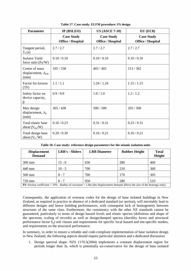
Table 17. Case study: ELFM procedure: FS design
Parameter JP (BSLEO) US (ASCE 7-10) EU (EC8)
Case Study
Office / Hospital
Case Study
Office / Hospital
Case Study
Office / Hospital
Tangent period,
T2 (s)
2.7 / 2.7 2.7 / 2.7 2.7 / 2.7
Isolator Yield
force ratio (Fy/W)
0.10 / 0.10 0.10 / 0.10 0.10 / 0.10
Centre of mass
displacement, CM
(mm)
105 / 238 402 / 402 213 / 362
Factor for torsion
(TF)
1.1 / 1.1 1.24 / 1.24 1.15 / 1.15
Safety factor on
device capacity,
0.9 / 0.9 1.0 / 1.0 1.2 / 1.2
Max design
displacement, d
(mm)
305 / 438 500 / 500 293 / 500
Total elastic base
shear (Vb,e/W)
0.16 / 0.23 0.31 / 0.31 0.23 / 0.31
Total design base
shear (Vb /W)
0.20 / 0.30 0.16 / 0.21 0.16 / 0.21
Table 18. Case study: reference design parameters for the seismic isolation units
Displacement
Demand
LRB's - Sliders LRB Diameter Rubber Height Total
Height
300 mm 15 - 0 650 280 460
440 mm 10 - 5 700 210 360
500 mm 8 - 7 700 170 305
720 mm 8 - 7 950 280 510 FS: friction coefficient = 10% - Radius of curvature = 1.8m (the displacement demand affects the size of the bearings only).
Consequently, the application of overseas codes for the design of base isolated buildings in New
Zealand, as required in practice in absence of a dedicated standard (or section), will inevitably lead to
different designs and hence building performances, with consequent lack of homogeneity between
structures of the same class. Furthermore, the consistency with the other NZ standards cannot be
guaranteed, particularly in terms of design hazard levels and elastic spectra (definition and shape of
the spectrum, scaling of records) as well as design/damped spectra (ductility factor and structural
performance factor Sp) soil classes and requirements for specific local hazard and site-specific studies,
and requirements on the structural performance.
In summary, in order to ensure a reliable and code-compliant implementation of base isolation design
in New Zealand, the following aspects should require particular attention and a dedicated discussion:
1. Design spectral shape: NZS 1170.5(2004) implements a constant displacement region for
periods longer than 3s, which is potentially un-conservative for the design of base isolated
24
systems with longer periods in the 4 to 6 second range, if not otherwise justified by the local
nature of the seismic motion. For example, recent research on Probabilistic Seismic Hazard
Study (PSHA) to define the long period seismic hazard for the Italian territory (Faccioli and
Villani, 2009), produced new hazard maps for the country in terms of horizontal displacement
response spectral ordinates for a wide range of vibration periods, from 0.05s up to 20s,
showing the tendency for the displacement demand to remain constant, or decrease, at long
periods.
2. The appropriate value if not, in more general sense, the actual role of Sp factor as included in
NZS1170.5 when dealing with base isolated structures: careful consideration should be given
in particular when considering the evaluation of the design displacement (demand) on the
isolators. While all the international codes reviewed do adopt reduction factors on the elastic
base shear for the design of the superstructure, none seems to incorporate a reduction factor
similar in concept or in practice to the Sp factor of the NZ standard, to the design
displacement (demand). If any, there are actually magnification factors on the design
displacement of the isolators.
3. Criteria requirements for a local seismic hazard study to be performed (under which
circumstances and depending on the design approach).
4. Design levels (DBE and/or MCE?), importance factors and additional safety/magnification
factors that should be used – these may differ for IL2 and IL4 buildings.
5. Design boundaries on the adoption of simplified ELF procedures.
6. Performance objectives/requirements for the isolators and the structure.
7. Quality Control testing procedures and acceptance requirements for isolators
8. Capacity design process and consideration of variations in the isolators’ properties.
9. What level of reduction factors for the superstructure base shear and drift/ductility limits for
the superstructure response
10. Structural detailing requirements (fully ductile, nominally ductile, with or without capacity
design considerations).
11. Consideration of floor acceleration spectra and requirements for non-structural components.
12. Peer review process.
4 CONCLUSIONS
The overview of three major international codes for the design of base isolated buildings has outlined
the current differences, in some cases relevant, in the design/approval process as well as in the
structural design requirements and calculation methods. With this in mind, and considering the current
lack of a NZ standard on the subject (as well as the lessons learnt from the Canterbury earthquakes
sequence and the revamped interest into a wider implementation of cost-efficient low-damage
structural systems including base-isolation), it is in the authors’ opinion that the engineering
community in the country should effectively collaborate at national and international level towards the
development of a NZ-specific design “code”, or endorsed guidelines, for base-isolated buildings.
Such document could bring together the current best practice in NZ and overseas, whilst assuring
consistency with the current standards as well as homogeneity in the design of base-isolated structures
throughout the country.
REFERENCES
AASHTO. 1999. Guide Specifications for Seismic Isolation Design, American Association of State Highway and Transportation Officials, Washington (D.C., US).
ASCE 7-10. 2010. Minimum Design Loads for Buildings and Other Structures, ASCE, Reston (Virginia, US).
25
Becker, T.C., Furukawa, S, Mahin, S.A. & Nakashima, M. 2010. Comparison of US and Japanese Codes and Practices for Seismically Isolated Buildings, 2010 Structures Congress, ASCE (US).
COSMOS. 2010. Practical application of the new ASCE 7-10 required procedures for determining site specific ground motions, COSMOS, Richmond, CA (US), November 2010.
EN 1998-1:2004. Eurocode 8: Design of structures for earthquake resistance - Part 1: General rules, seismic actions and rules for buildings, CEN, Brussels (Belgium, EU).
Faccioli, E. & Villani, M. 2009. Seismic hazard mapping for Italy in terms of broadband displacement response spectra. Earthquake Spectra 25, 515-539.
Feng, D., Liu, W. Masuda,K., Wang, S. & Huan, S. 2006a. – A comparative study of seismic isolation codes worldwide - part I: Design spectrum, 1
st ECEES, paper N. 63, Geneva, 2006.
Feng, D., Liu, W. Masuda,K., Wang, S. & Huan, S. 2006b. – A comparative study of seismic isolation codes worldwide - part II: Response analysis, 1
st ECEES, paper N. 66, Geneva, 2006.
Higashino, M. & Okamoto, S. 2006. Response control and seismic isolation of buildings, Taylor & Francis, New York (US).
Kani, N. & Otani, S. 2002. Japanese State of Practice in Design of Seismically Isolated Buildings, The Fourth U.S.-Japan Workshop on Performance-Based Earthquake Engineering Methodology for Reinforced Concrete Building Structures, 22–24 October 2002, Toba, Japan, PEER 2002/21, DEC. 2002, Pacific Earthquake Engineering research center, Berkeley (California, US).
Kani, N., Feng, D. & Sera, S. 2010. Performance Based Design of Seismically Isolated Buildings in Japan, Workshop: Bridges seismic isolation and large scale modeling, St.-Petersburg, Russia, June 29th - July 3rd, 2010.
Midorikawa, M., Okawa, I., Iiba, M. & Teshigawara, M. 2003. Performance-Based Design Code for Buildings in Japan, Earthquake Engineering and Engineering Seismology, Vol. 4, No. 1.
Nakashima, M. & Chusilp, P. 2003. A Partial View of Japanese Post-Kobe Seismic Design and Construction Practices, Earthquake Engineering and Engineering Seismology, Vol. 4, No. 1
NEHRP. 2011. Selecting and scaling earthquake ground motions for performing response-history analyses, NIST GCR 11-917-15 report, November 2011.
NTC08. 2008. Norme tecniche per le costruzioni– DM 14-01-2008, Italy
NZS 1170.5:2004. Structural Design Actions – Part 5: Earthquake actions – New Zealand, Standards New Zealand, Wellington (NZ).