Embed Size (px)
Citation preview
24
Reuse MATLAB® Functions and Simulink® Models in UVM Environments with Automatic SystemVerilog DPI Component Generation by Tao Jia, HDL Verifier Development Lead, and Jack Erickson, HDL Product Marketing Manager, MathWorks
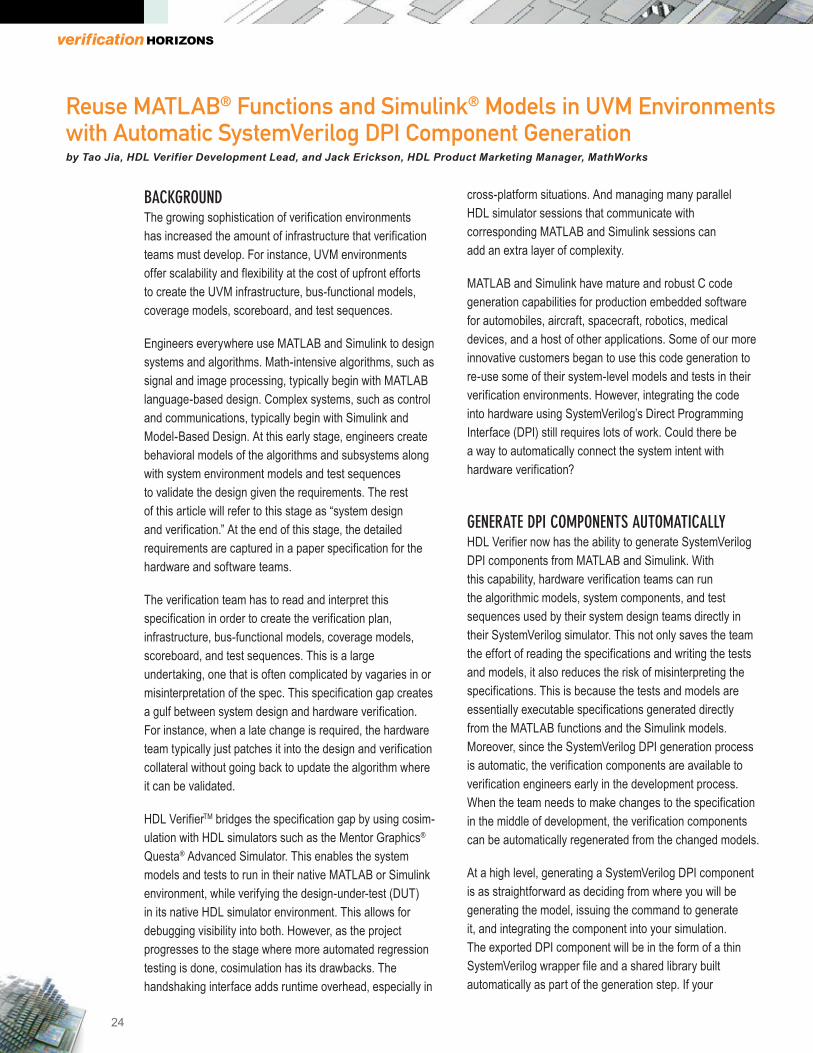
BACKGROUND The growing sophistication of verification environments has increased the amount of infrastructure that verification teams must develop. For instance, UVM environments offer scalability and flexibility at the cost of upfront efforts to create the UVM infrastructure, bus-functional models, coverage models, scoreboard, and test sequences.
Engineers everywhere use MATLAB and Simulink to design systems and algorithms. Math-intensive algorithms, such as signal and image processing, typically begin with MATLAB language-based design. Complex systems, such as control and communications, typically begin with Simulink and Model-Based Design. At this early stage, engineers create behavioral models of the algorithms and subsystems along with system environment models and test sequences to validate the design given the requirements. The rest of this article will refer to this stage as “system design and verification.” At the end of this stage, the detailed requirements are captured in a paper specification for the hardware and software teams.
The verification team has to read and interpret this specification in order to create the verification plan, infrastructure, bus-functional models, coverage models, scoreboard, and test sequences. This is a large undertaking, one that is often complicated by vagaries in or misinterpretation of the spec. This specification gap creates a gulf between system design and hardware verification. For instance, when a late change is required, the hardware team typically just patches it into the design and verification collateral without going back to update the algorithm where it can be validated.
HDL VerifierTM bridges the specification gap by using cosim- ulation with HDL simulators such as the Mentor Graphics® Questa® Advanced Simulator. This enables the system models and tests to run in their native MATLAB or Simulink environment, while verifying the design-under-test (DUT) in its native HDL simulator environment. This allows for debugging visibility into both. However, as the project progresses to the stage where more automated regression testing is done, cosimulation has its drawbacks. The handshaking interface adds runtime overhead, especially in
cross-platform situations. And managing many parallel HDL simulator sessions that communicate with corresponding MATLAB and Simulink sessions can add an extra layer of complexity.
MATLAB and Simulink have mature and robust C code generation capabilities for production embedded software for automobiles, aircraft, spacecraft, robotics, medical devices, and a host of other applications. Some of our more innovative customers began to use this code generation to re-use some of their system-level models and tests in their verification environments. However, integrating the code into hardware using SystemVerilog’s Direct Programming Interface (DPI) still requires lots of work. Could there be a way to automatically connect the system intent with hardware verification?
GENERATE DPI COMPONENTS AUTOMATICALLY HDL Verifier now has the ability to generate SystemVerilog DPI components from MATLAB and Simulink. With this capability, hardware verification teams can run the algorithmic models, system components, and test sequences used by their system design teams directly in their SystemVerilog simulator. This not only saves the team the effort of reading the specifications and writing the tests and models, it also reduces the risk of misinterpreting the specifications. This is because the tests and models are essentially executable specifications generated directly from the MATLAB functions and the Simulink models. Moreover, since the SystemVerilog DPI generation process is automatic, the verification components are available to verification engineers early in the development process. When the team needs to make changes to the specification in the middle of development, the verification components can be automatically regenerated from the changed models.
At a high level, generating a SystemVerilog DPI component is as straightforward as deciding from where you will be generating the model, issuing the command to generate it, and integrating the component into your simulation. The exported DPI component will be in the form of a thin SystemVerilog wrapper file and a shared library built automatically as part of the generation step. If your

25
Reuse MATLAB® Functions and Simulink® Models in UVM Environments with Automatic SystemVerilog DPI Component Generation by Tao Jia, HDL Verifier Development Lead, and Jack Erickson, HDL Product Marketing Manager, MathWorks
simulation runs on a different platform than from where it’s generated, you can use the generated makefile to build the shared library on that platform.
These components run quickly in simulation, as they are behavioral-level C code without the bit-level implementation details. Using C as the description language allows you to export a wide variety of model types. Some example applications include:
• Bus-functional checker algorithm for UVM scoreboard• UVM sequence item• Analog model representation in SoC UVM
environment• Digital model in an analog circuit simulator
This article uses an example FFT design to demonstrate how to generate a bus-functional checker algorithm written in MATLAB, and it outlines how to integrate it into a UVM scoreboard.
Image 1: Generating a SystemVerilog DPI component
from a MATLAB algorithm for use in a UVM
scoreboard. ©2015 The MathWorks, Inc.
SETTING UP AND GENERATING THE DPI COMPONENT The first step is to identify what you will need the component to do in your verification environment. In other words, how will it be used? What will the primary inputs
and outputs be? What other signals will you need access to? In our example, we will generate a checker function that will calculate the floating point result of a 64-point radix-2 FFT and compare this to the outputs of a fixed-point RTL implementation.
Image 2: MATLAB code for the checker function.
©2015 The MathWorks, Inc.
This function returns a ratio of the root-mean-square error of the fixed-point implementation versus floating-point reference outputs, divided by the root-mean-square of the fixed-point implementation outputs.
This is a good time to check whether your model is compatible with code generation. SystemVerilog DPI component generation relies on underlying C code generation technology from MATLAB Coder or Simulink Coder, and there are certain requirements models need to comply with for code generation. Running one of the code generation checking utilities helps to identify and remedy many potential issues before you try to generate a DPI component:
• MATLAB: Add the %#codegen directive (or pragma) to your function after the function signature to indicate that you intend to generate code for the MATLAB algorithm. Adding this directive instructs the MATLAB code analyzer to help you diagnose and fix violations that would result in errors during code generation, such as blocks, functions, or features not supported for C code generation.

26
• MATLAB: Select your file in the current folder and right click Check Code Generation Readiness.
• Simulink: Select your subsystem, right click C/C+ Code > Code Generation Advisor
At this point, you can generate the model using the default settings or customizing the output. This example generates the DPI component from MATLAB, which uses the dpigen command:
dpigen -args {int16(ones(1,64)),int16(ones(1,64)),int16(ones(1,64)),int16(ones(1,64))} fft_checker
We specify the function’s input types and size (the –args argument), and the name of the MATLAB function from which we’re generating (fft_checker). The generated testbench is a SystemVerilog file that reads input vectors and expected output vectors from the MATLAB testbench to verify that the DPI component is functionally equivalent to the original MATLAB function.
To generate the DPI component from Simulink, use a parallel workflow, but with the Simulink UI infrastructure. Set up by selecting the Code > C/C++ Code > Code Generation Options pull down menu. On this form, you first need to specify that it will be a DPI component
by browsing in System target file and selecting systemverilog_dpi_grt.tlc.
Once you are satisfied with your settings, click OK to close the form. Then select the subsystem for which you want to generate the DPI component by right clicking C/C++ Code > Build This Subsystem.
Building the subsystem in Simulink, or running dpigen in MATLAB, will generate the collateral necessary to build your DPI component including the C files for the core function and its DPI interface, the necessary header files, a SystemVerilog wrapper, and a makefile. By default, it will even build the shared library to load into the simulator. Of course, if your simulation runs on a different platform, you will want to use the generated makefile to build the shared library on that platform.
INTEGRATING THE DPI COMPONENT INTO SIMULATION The shared library encapsulates everything you need for the component to execute; you just need to point your simulator to it at runtime (more on that later). First, you need to make the SystemVerilog side aware of it. This SystemVerilog file was generated as part of the build process:
27
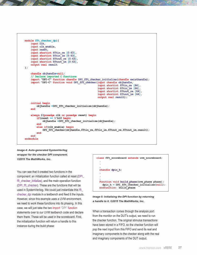
Image 4: Auto-generated SystemVerilog
wrapper for the checker DPI component.
©2015 The MathWorks, Inc.
You can see that it created two functions in the component: an initialization function called at reset (DPI_fft_checker_initialize), and the main operation function (DPI_fft_checker). These are the functions that will be used in SystemVerilog. We could just instantiate this fft_checker_dpi module in a testbench and feed it the inputs. However, since this example uses a UVM environment, we need to work these functions into its phasing. In this case, we will just take the two import “DPI” function statements over to our UVM testbench code and declare them there. These will be used in the scoreboard. First, the initialization function will return a handle to this instance during the build phase:
Image 5: Initializing the DPI function by returning
a handle to it. ©2015 The MathWorks, Inc.
When a transaction comes through the analysis port from the monitor on the DUT’s output, we need to run the checker function. The original stimulus transactions have been stored in a FIFO, so the checker function will pop the next input from this FIFO and send its real and imaginary components to the checker along with the real and imaginary components of the DUT output.

28
Image 6: Sending the stimulus transaction and
implementation output data into the checker, and
comparing the result against the defined threshold.
© 2015 The MathWorks, Inc.
The return value, nmrs, is the return value from the MATLAB function. HDL Verifier created an output port for it when it created the SystemVerilog wrapper. This is compared against a threshold of error tolerance that we defined in our UVM testbench.
So now our verification environment looks something like this, with the scoreboard receiving transactions from the driver and monitor via analysis ports:
Image 7: High-level block diagram of the UVM environ-
ment and where the generated SystemVerilog DPI
component is used. © 2015 The MathWorks, Inc.
At this point, we can run simulation. Remember, we need to point the simulator to our shared library. Here’s how we do it with the Questa simulator:
Image 8: Questa Advanced Simulator run script,
pointing to the generated shared library.
© 2015 The MathWorks, Inc.
In the above script, libfft_checker_dpi is the name of the shared library automatically generated by HDL Verifier from the MATLAB function fft_checker.
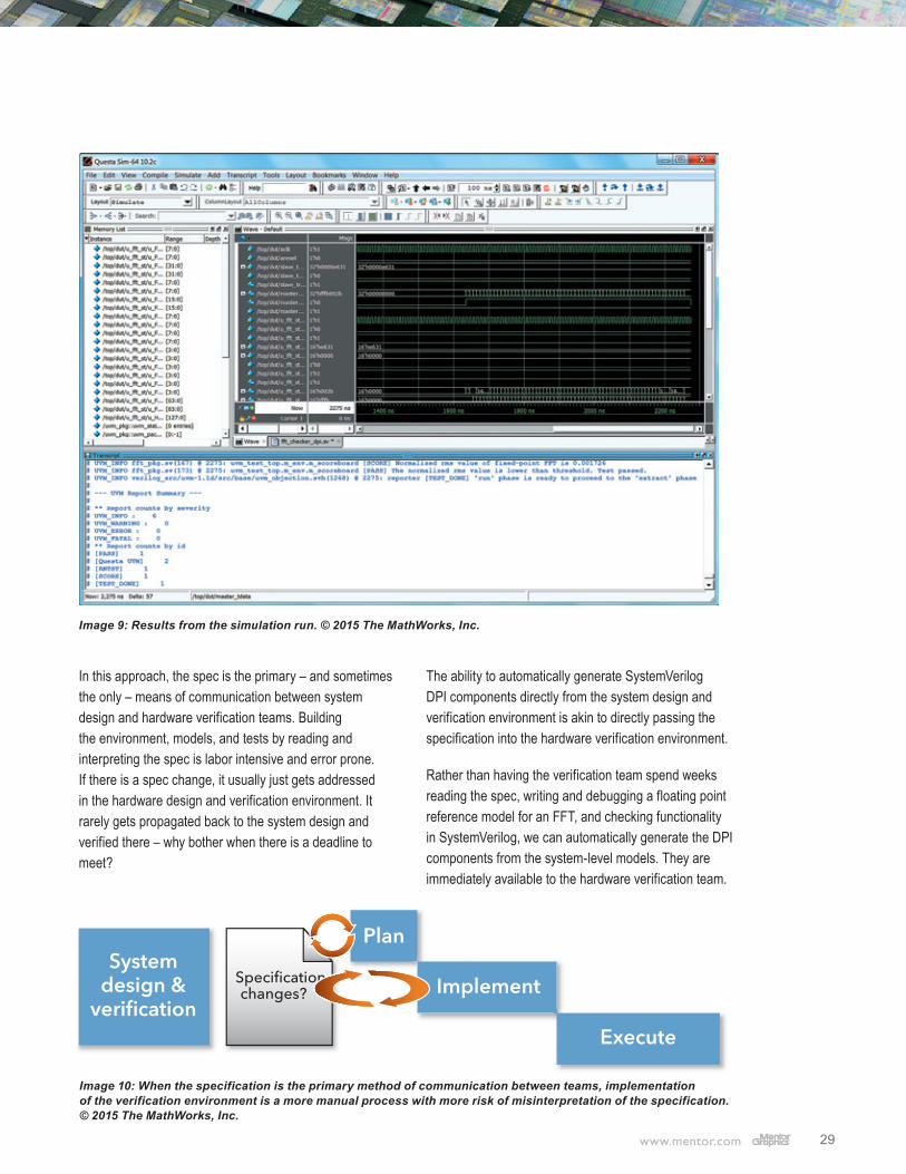
RESULTS This simple example shows how to generate SystemVerilog DPI components using HDL Verifier, and it illustrates how to integrate the generated components into a UVM environment. The simulation passes its simple test sequence (see image 9):
What effect did this have on our verification efforts? The high-level phases of a verification
project typically include developing the verification plan, implementing the verification environment, and executing verification. The plan and implementation are driven primarily through reading and interpreting the specification, and that spec is written as a result of the design and verification efforts of the system team.
29
In this approach, the spec is the primary – and sometimes the only – means of communication between system design and hardware verification teams. Building the environment, models, and tests by reading and interpreting the spec is labor intensive and error prone. If there is a spec change, it usually just gets addressed in the hardware design and verification environment. It rarely gets propagated back to the system design and verified there – why bother when there is a deadline to meet?
The ability to automatically generate SystemVerilog DPI components directly from the system design and verification environment is akin to directly passing the specification into the hardware verification environment.
Rather than having the verification team spend weeks reading the spec, writing and debugging a floating point reference model for an FFT, and checking functionality in SystemVerilog, we can automatically generate the DPI components from the system-level models. They are immediately available to the hardware verification team.
Image 9: Results from the simulation run. © 2015 The MathWorks, Inc.
30
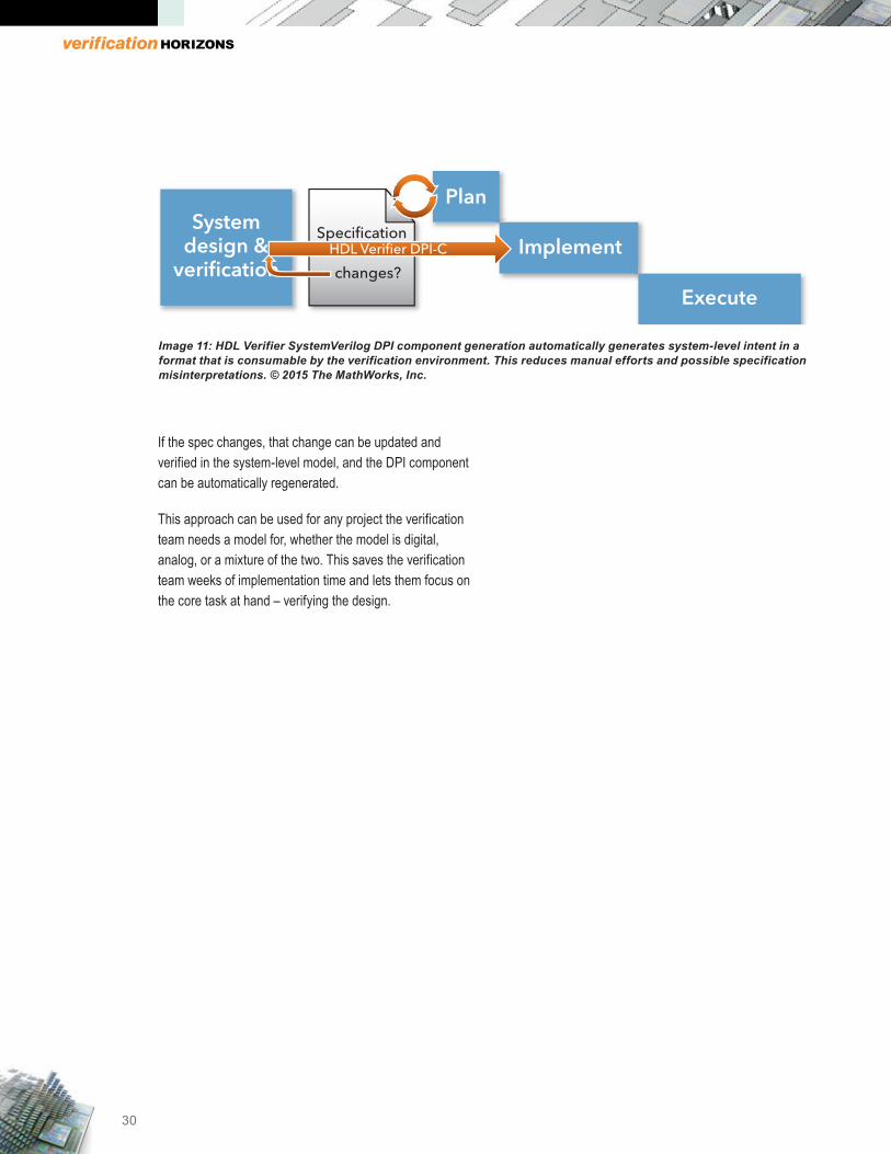
If the spec changes, that change can be updated and verified in the system-level model, and the DPI component can be automatically regenerated.
This approach can be used for any project the verification team needs a model for, whether the model is digital, analog, or a mixture of the two. This saves the verification team weeks of implementation time and lets them focus on the core task at hand – verifying the design.
Image 11: HDL Verifier SystemVerilog DPI component generation automatically generates system-level intent in a format that is consumable by the verification environment. This reduces manual efforts and possible specification misinterpretations. © 2015 The MathWorks, Inc.

VERIFICATION ACADEMY
The Most Comprehensive Resource for Verification Training
21 Video Courses Available Covering
• Intelligent Testbench Automation• Metrics in SoC Verification• Verification Planning• Introductory, Basic, and Advanced UVM• Assertion-Based Verification• FPGA Verification• Testbench Acceleration• Power Aware Verification• Analog Mixed-Signal Verification
UVM and Coverage Online Methodology Cookbooks
Discussion Forum with more than 5000 topics
UVM Connect and UVM Express Kits
www. verificationacademy.com

Editor: Tom FitzpatrickProgram Manager: Rebecca Granquist
Wilsonville Worldwide Headquarters8005 SW Boeckman Rd.Wilsonville, OR 97070-7777Phone: 503-685-7000
To subscribe visit: www.mentor.com/horizons
To view our blog visit:VERIFICATIONHORIZONSBLOG.COM