Embed Size (px)
Citation preview
www.reactive-systems.com
Testing and Validationof Simulink Modelswith Reactis
Build better embedded software faster. Generate tests from Simulink
models. Detect runtime errors. Execute and debug Simulink models.
Track coverage. Automate functional testing of requirements. Check
conformance of code to model.
RSITR 1.11October 19, 2013
Contents
1 Introduction 1
2 An Overview of Reactis 22.1 Reactis Tester . . . . . . . . . . . . . . . . . . . . . . . . . . . . . . . . . . . . . . 22.2 Reactis Simulator . . . . . . . . . . . . . . . . . . . . . . . . . . . . . . . . . . . . 42.3 Reactis Validator . . . . . . . . . . . . . . . . . . . . . . . . . . . . . . . . . . . . 4
3 Advanced Model Validation 53.1 Debugging with Tester and Simulator . . . . . . . . . . . . . . . . . . . . . . . . 53.2 Validating Models with Validator . . . . . . . . . . . . . . . . . . . . . . . . . . . 6
4 Testing Code Against Model 84.1 Software Testing . . . . . . . . . . . . . . . . . . . . . . . . . . . . . . . . . . . . . 84.2 System Testing . . . . . . . . . . . . . . . . . . . . . . . . . . . . . . . . . . . . . . 9
5 Reverse Engineering Models from Legacy Code 10
6 Conclusions 11
About Reactive Systems, Inc.Reactive Systems, founded in 1999, is a privately held company based in Cary, NC. The com-pany’s Reactis product line provides automated testing and validation tools to support thedevelopment of embedded control software. Reactis, Reactis for C Plugin, Reactis for EMLPlugin, Reactis Model Inspector, and Reactis for C support model-based design with Simulink,Stateflow, Embedded MATLAB, and C code. Reactis Tester automatically generates compre-hensive yet compact test suites from a Simulink model or C code. Reactis is used at companiesworldwide in the automotive, aerospace, and heavy-equipment industries.
Reactive Systems, Inc.341 Kilmayne Dr.
Suite 101Cary, NC 27511
USA
Tel.: +1 919-324-3507Fax: +1 919-324-3508
Web: www.reactive-systems.comE-mail: [email protected]
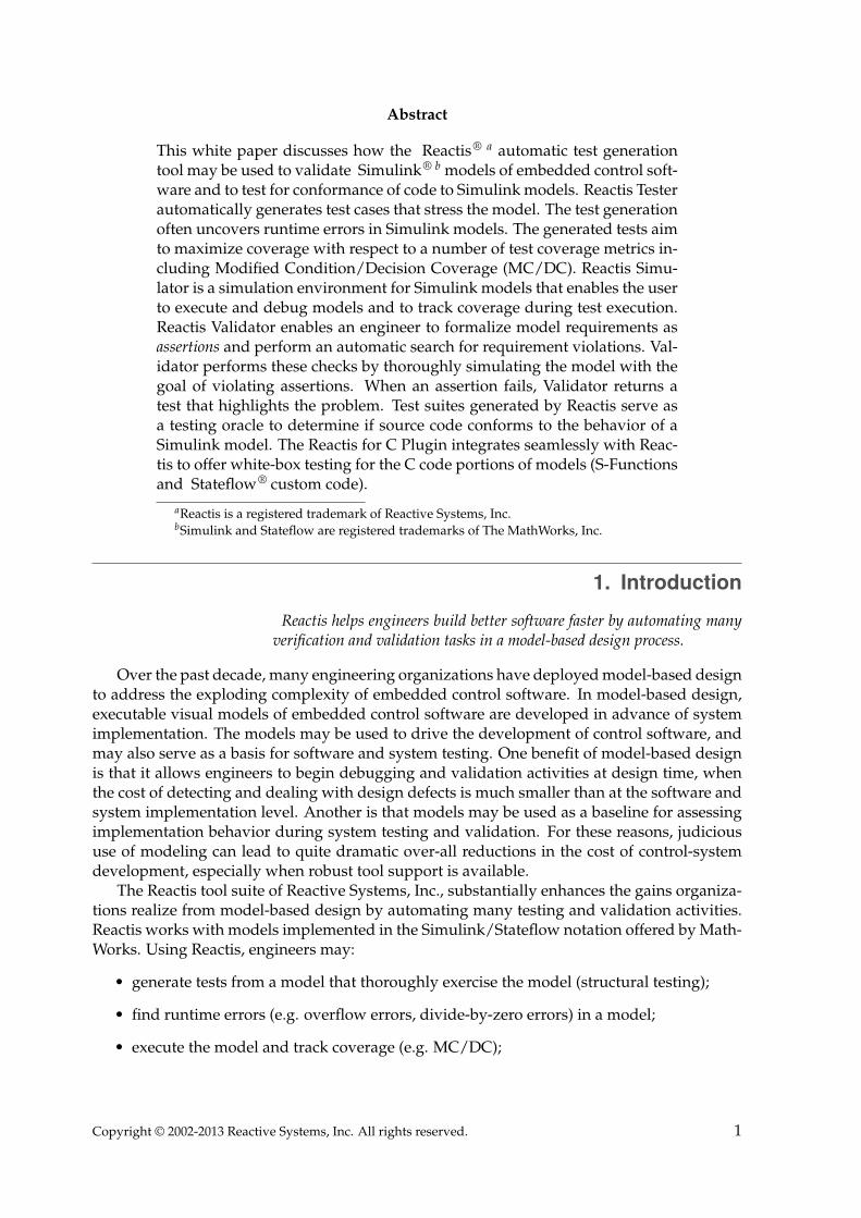
Abstract
This white paper discusses how the Reactis® a automatic test generationtool may be used to validate Simulink® b models of embedded control soft-ware and to test for conformance of code to Simulink models. Reactis Testerautomatically generates test cases that stress the model. The test generationoften uncovers runtime errors in Simulink models. The generated tests aimto maximize coverage with respect to a number of test coverage metrics in-cluding Modified Condition/Decision Coverage (MC/DC). Reactis Simu-lator is a simulation environment for Simulink models that enables the userto execute and debug models and to track coverage during test execution.Reactis Validator enables an engineer to formalize model requirements asassertions and perform an automatic search for requirement violations. Val-idator performs these checks by thoroughly simulating the model with thegoal of violating assertions. When an assertion fails, Validator returns atest that highlights the problem. Test suites generated by Reactis serve asa testing oracle to determine if source code conforms to the behavior of aSimulink model. The Reactis for C Plugin integrates seamlessly with Reac-tis to offer white-box testing for the C code portions of models (S-Functionsand Stateflow® custom code).
aReactis is a registered trademark of Reactive Systems, Inc.bSimulink and Stateflow are registered trademarks of The MathWorks, Inc.
1. IntroductionReactis helps engineers build better software faster by automating many
verification and validation tasks in a model-based design process.
Over the past decade, many engineering organizations have deployed model-based designto address the exploding complexity of embedded control software. In model-based design,executable visual models of embedded control software are developed in advance of systemimplementation. The models may be used to drive the development of control software, andmay also serve as a basis for software and system testing. One benefit of model-based designis that it allows engineers to begin debugging and validation activities at design time, whenthe cost of detecting and dealing with design defects is much smaller than at the software andsystem implementation level. Another is that models may be used as a baseline for assessingimplementation behavior during system testing and validation. For these reasons, judicioususe of modeling can lead to quite dramatic over-all reductions in the cost of control-systemdevelopment, especially when robust tool support is available.
The Reactis tool suite of Reactive Systems, Inc., substantially enhances the gains organiza-tions realize from model-based design by automating many testing and validation activities.Reactis works with models implemented in the Simulink/Stateflow notation offered by Math-Works. Using Reactis, engineers may:
• generate tests from a model that thoroughly exercise the model (structural testing);
• find runtime errors (e.g. overflow errors, divide-by-zero errors) in a model;
• execute the model and track coverage (e.g. MC/DC);
Copyright © 2002-2013 Reactive Systems, Inc. All rights reserved. 1

• perform functional tests to check whether or not a model can violate its requirements;
• use a Reactis test suite as an oracle to check whether code conforms to a model.
Reactis also includes an array of sophisticated model debug features (e.g. breakpoints,scopes, reverse execution). In this paper, we discuss how Reactis and model-based design maybe used to automate different verification and validation activities in your software qualityassurance process. In particular, we show how the tool may be used to develop more robustmodels, how it can streamline software and system testing, and how it may be used to supportthe reverse-engineering of models from legacy code.
2. An Overview of ReactisA model-based design environment involving Reactis, Simulink and Stateflow is depictedin Figure 1. Reactis contains three core components: Tester, which provides automated testgeneration from models; Simulator, which enables you to visualize model execution to debugmodels and track coverage; and Validator, which offers automated checks of Simulink modelsfor violations of user-specified requirements. The remainder of this section describes thesecomponents in more detail.
Figure 1: Reactis is used in a model-based design process using Simulink/Stateflow models.Reactis is a standalone application that reads the .mdl/.slx files produced by the MathWorksenvironment.
2.1. Reactis TesterFigure 2 shows that Reactis Tester offers automatic test generation from Simulink models.The generated test suites provide comprehensive coverage of different test coverage metrics -including the Modified Condition/Decision Coverage (MC/DC) test coverage measure mandatedby the US Federal Aviation Administration (FAA) in its DO-178/B guidelines - while at thesame time minimizing redundancy in tests. Each test case in a test suite consists of a sequenceof inputs fed into the model as well as the responses to those inputs generated by the model.
The automatically generated test data may then be used for a variety of purposes, includ-ing the following:
Implementation conformance. The tests may be applied to source-code implementations ofmodels to ensure conformance with model behavior.
Model testing and debugging. The tests may be run on the models themselves to detect run-time errors and to study and revise model behavior.
Regression testing of models. The tests may be run on a new versions of models to flag dif-fering behaviors in new versions.
Copyright © 2002-2013 Reactive Systems, Inc. All rights reserved. 2
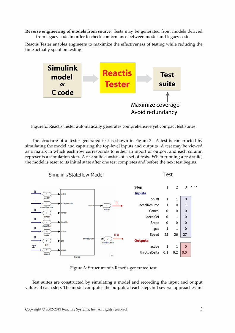
Reverse engineering of models from source. Tests may be generated from models derivedfrom legacy code in order to check conformance between model and legacy code.
Reactis Tester enables engineers to maximize the effectiveness of testing while reducing thetime actually spent on testing.
Figure 2: Reactis Tester automatically generates comprehensive yet compact test suites.
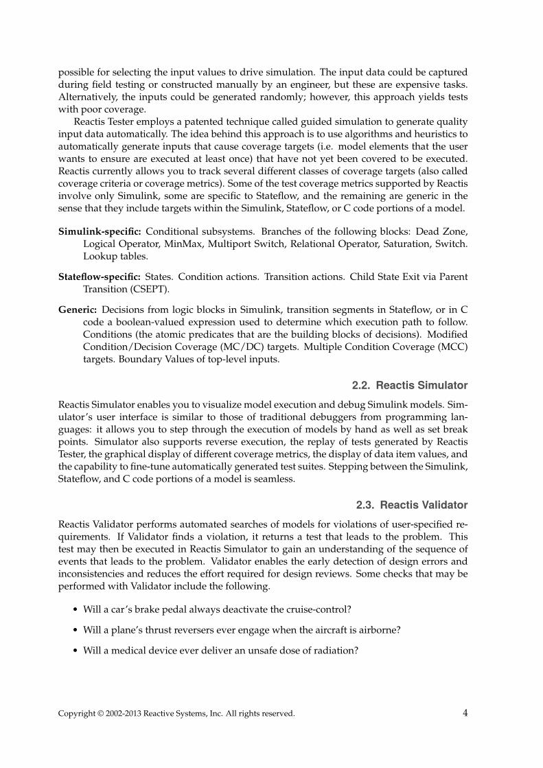
The structure of a Tester-generated test is shown in Figure 3. A test is constructed bysimulating the model and capturing the top-level inputs and outputs. A test may be viewedas a matrix in which each row corresponds to either an inport or outport and each columnrepresents a simulation step. A test suite consists of a set of tests. When running a test suite,the model is reset to its initial state after one test completes and before the next test begins.
Figure 3: Structure of a Reactis-generated test.
Test suites are constructed by simulating a model and recording the input and outputvalues at each step. The model computes the outputs at each step, but several approaches are
Copyright © 2002-2013 Reactive Systems, Inc. All rights reserved. 3
possible for selecting the input values to drive simulation. The input data could be capturedduring field testing or constructed manually by an engineer, but these are expensive tasks.Alternatively, the inputs could be generated randomly; however, this approach yields testswith poor coverage.
Reactis Tester employs a patented technique called guided simulation to generate qualityinput data automatically. The idea behind this approach is to use algorithms and heuristics toautomatically generate inputs that cause coverage targets (i.e. model elements that the userwants to ensure are executed at least once) that have not yet been covered to be executed.Reactis currently allows you to track several different classes of coverage targets (also calledcoverage criteria or coverage metrics). Some of the test coverage metrics supported by Reactisinvolve only Simulink, some are specific to Stateflow, and the remaining are generic in thesense that they include targets within the Simulink, Stateflow, or C code portions of a model.
Simulink-specific: Conditional subsystems. Branches of the following blocks: Dead Zone,Logical Operator, MinMax, Multiport Switch, Relational Operator, Saturation, Switch.Lookup tables.
Stateflow-specific: States. Condition actions. Transition actions. Child State Exit via ParentTransition (CSEPT).
Generic: Decisions from logic blocks in Simulink, transition segments in Stateflow, or in Ccode a boolean-valued expression used to determine which execution path to follow.Conditions (the atomic predicates that are the building blocks of decisions). ModifiedCondition/Decision Coverage (MC/DC) targets. Multiple Condition Coverage (MCC)targets. Boundary Values of top-level inputs.
2.2. Reactis SimulatorReactis Simulator enables you to visualize model execution and debug Simulink models. Sim-ulator’s user interface is similar to those of traditional debuggers from programming lan-guages: it allows you to step through the execution of models by hand as well as set breakpoints. Simulator also supports reverse execution, the replay of tests generated by ReactisTester, the graphical display of different coverage metrics, the display of data item values, andthe capability to fine-tune automatically generated test suites. Stepping between the Simulink,Stateflow, and C code portions of a model is seamless.
2.3. Reactis ValidatorReactis Validator performs automated searches of models for violations of user-specified re-quirements. If Validator finds a violation, it returns a test that leads to the problem. Thistest may then be executed in Reactis Simulator to gain an understanding of the sequence ofevents that leads to the problem. Validator enables the early detection of design errors andinconsistencies and reduces the effort required for design reviews. Some checks that may beperformed with Validator include the following.
• Will a car’s brake pedal always deactivate the cruise-control?
• Will a plane’s thrust reversers ever engage when the aircraft is airborne?
• Will a medical device ever deliver an unsafe dose of radiation?
Copyright © 2002-2013 Reactive Systems, Inc. All rights reserved. 4

3. Advanced Model ValidationThe model-validation capabilities of Reactis help engineers detect bugs
earlier, when they are less costly to fix.
A primary benefit of model-based design is that it allows the detection and correction ofsystem-design defects at design (i.e. modeling) time, when they are much less expensive andtime consuming to correct, rather than at system-implementation and testing time. Moreover,with proper tool support, the probability of detecting defects at the model level can be signif-icantly increased. In this section, we elaborate on the advanced model-validation capabilitiesof Reactis that help engineers build better models.
3.1. Debugging with Tester and SimulatorReactis Tester and Simulator support model debugging through the automatic generationof test suites that thoroughly exercise the model under investigation (Reactis Tester), andthrough the visualization of tests as they are executed on the model (Reactis Simulator). Onesuch usage scenario of Tester and Simulator is shown in Figure 4. Since Tester’s guided-simulation test-generation algorithm thoroughly simulates a model during test generation, itoften uncovers runtime errors. For example, overflows, missing cases, and bad array indexescan be discovered. Note that this type of error is also detected when running simulationsin Simulink; however, since Tester’s guided-simulation engine systematically exercises themodel much more thoroughly than random simulation can, the probability of finding suchmodeling problems is much higher using Reactis.
Figure 4: Debugging Simulink models with Reactis Tester and Reactis Simulator
Copyright © 2002-2013 Reactive Systems, Inc. All rights reserved. 5
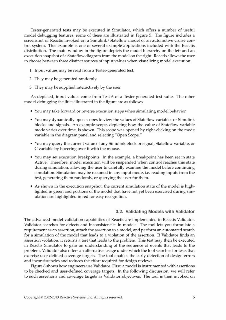
Tester-generated tests may be executed in Simulator, which offers a number of usefulmodel debugging features; some of these are illustrated in Figure 5. The figure includes ascreenshot of Reactis invoked on a Simulink/Stateflow model of an automotive cruise con-trol system. This example is one of several example applications included with the Reactisdistribution. The main window in the figure depicts the model hierarchy on the left and anexecution snapshot of a Stateflow diagram from the model on the right. Reactis allows the userto choose between three distinct sources of input values when visualizing model execution:
1. Input values may be read from a Tester-generated test.
2. They may be generated randomly.
3. They may be supplied interactively by the user.
As depicted, input values come from Test 6 of a Tester-generated test suite. The othermodel-debugging facilities illustrated in the figure are as follows.
• You may take forward or reverse execution steps when simulating model behavior.
• You may dynamically open scopes to view the values of Stateflow variables or Simulinkblocks and signals. An example scope, depicting how the value of Stateflow variablemode varies over time, is shown. This scope was opened by right-clicking on the modevariable in the diagram panel and selecting “Open Scope.”
• You may query the current value of any Simulink block or signal, Stateflow variable, orC variable by hovering over it with the mouse.
• You may set execution breakpoints. In the example, a breakpoint has been set in stateActive. Therefore, model execution will be suspended when control reaches this stateduring simulation, allowing the user to carefully examine the model before continuingsimulation. Simulation may be resumed in any input mode, i.e. reading inputs from thetest, generating them randomly, or querying the user for them.
• As shown in the execution snapshot, the current simulation state of the model is high-lighted in green and portions of the model that have not yet been exercised during sim-ulation are highlighted in red for easy recognition.
3.2. Validating Models with ValidatorThe advanced model-validation capabilities of Reactis are implemented in Reactis Validator.Validator searches for defects and inconsistencies in models. The tool lets you formulate arequirement as an assertion, attach the assertion to a model, and perform an automated searchfor a simulation of the model that leads to a violation of the assertion. If Validator finds anassertion violation, it returns a test that leads to the problem. This test may then be executedin Reactis Simulator to gain an understanding of the sequence of events that leads to theproblem. Validator also offers an alternative usage under which the tool searches for tests thatexercise user-defined coverage targets. The tool enables the early detection of design errorsand inconsistencies and reduces the effort required for design reviews.
Figure 6 shows how engineers use Validator. First, a model is instrumented with assertionsto be checked and user-defined coverage targets. In the following discussion, we will referto such assertions and coverage targets as Validator objectives. The tool is then invoked on
Copyright © 2002-2013 Reactive Systems, Inc. All rights reserved. 6
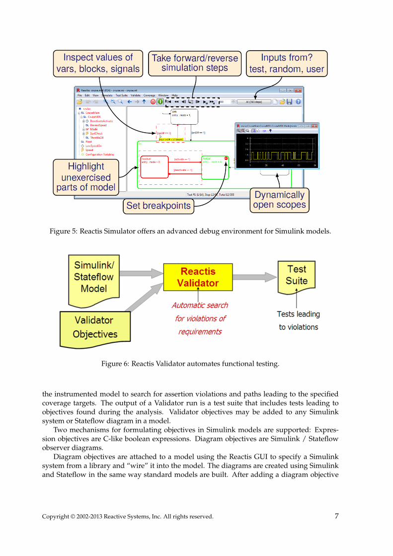
Figure 5: Reactis Simulator offers an advanced debug environment for Simulink models.
Figure 6: Reactis Validator automates functional testing.
the instrumented model to search for assertion violations and paths leading to the specifiedcoverage targets. The output of a Validator run is a test suite that includes tests leading toobjectives found during the analysis. Validator objectives may be added to any Simulinksystem or Stateflow diagram in a model.
Two mechanisms for formulating objectives in Simulink models are supported: Expres-sion objectives are C-like boolean expressions. Diagram objectives are Simulink / Stateflowobserver diagrams.
Diagram objectives are attached to a model using the Reactis GUI to specify a Simulinksystem from a library and “wire” it into the model. The diagrams are created using Simulinkand Stateflow in the same way standard models are built. After adding a diagram objective
Copyright © 2002-2013 Reactive Systems, Inc. All rights reserved. 7
to a model, the diagram will be included in the model’s hierarchy tree, just as library links arein a model. Note that the diagram objectives are stored in a separate library and the .mdl/.slxfile containing the controller model remains unchanged.
Because of its sophisticated model-debugging capabilities, the Reactis tool suite providessignificant added value to the MathWorks Simulink/Stateflow modeling environment. Thegreat virtue of model-level debugging is that it enables engineers to debug a software designbefore any source code is generated. The earlier logic errors are detected, the less costly theyare to fix.
4. Testing Code Against ModelThe automatic test-generation and execution offered by Reactis enables en-gineers to easily check whether an implementation conforms to the behaviorspecified in a model.
The benefits of model debugging and validation have been discussed above. A questionthat immediately presents itself is: How can the effort expended on these activities be “reused”to support the testing of system implementations? This is the question addressed in this sec-tion.
4.1. Software TestingA crucial aspect of the tests generated by Reactis Tester is that they also store model outputs.Therefore, these tests encode all the information needed to ensure that model-derived sourcecode conforms to its model. Reactis-driven source-code testing proceeds as follows:
1. For each test in the suite, execute the software using the input values contained in thetest.
2. Compare the output values produced by the software with those stored in the test.
3. Record any discrepancies.
This methodology is referred to as model-based software testing or back-to-back testing.Its key advantage is that the model serves as an “oracle” for testing purposes: the outputsproduced by the model can be used as a basis for assessing those generated by the software. Ifthe software does not agree with the model, then the developer can assume that the problemlies within the source code.
The net effect of model-based testing with Reactis is better-quality software at a lowercost. Because good test data is generated and run automatically, less engineer time is requiredto create and run tests. Because the tests are thorough, the probability of finding bugs ismaximized. Because the test suites are compact they may be run quickly. In sum, Reactisdramatically reduces the costs of testing embedded control software.
Figure 7 illustrates how the Reactis tool suite can provide advanced model-based testingof source code. As the figure indicates, the model-based testing protocol supported by Reactisis as follows:
1. The developer provides as input to Reactis a .mdl/.slx file representing the validatedSimulink/Stateflow model of the system under development.
Copyright © 2002-2013 Reactive Systems, Inc. All rights reserved. 8

Figure 7: Testing for conformance of code to model with Reactis.
2. Reactis Tester is used to automatically generate a test suite that thoroughly exercises thegiven model according to the various coverage metrics supported by Reactis.
3. The developer may deploy Reactis Simulator to visualize test execution and to fine tunethe tests in the test suite to further improve model coverage.
4. The test suite and the software implementing the model are fed as inputs into a testharness to automate the source-code testing process.
5. By comparing the outputs produced by the software against the model-generated out-puts (stored in the test), deviations in the behavior of the source code from the modelare readily detectable and help the developer ensure that the source code conforms tothe model.
6. Testing concludes when the source code passes all the tests in the test suite.
4.2. System TestingAfter software testing, the next step in certifying a system is to compile the code and testthe resulting executable on the platform, including the target microprocessor and associatedsystem software, on which it will eventually be deployed. Such testing is often referred to assystem, or integration, testing.
System testing typically involves the use of hardware-in-the-loop (HIL) simulation tools.These HIL tools are expensive, and thus using them as efficiently as possible can promotesignificant cost savings.
Provided that system-level models are given in Simulink / Stateflow, Reactis can greatlyfacilitate system testing. As in the case of software testing, test engineers can use Reactis Tester
Copyright © 2002-2013 Reactive Systems, Inc. All rights reserved. 9

and Reactis Simulator to generate thorough yet compact test suites from these models and feedthe test data into their HIL environments in order to check system behavior against modelbehavior. The compactness of Reactis-generated tests means that expensive HIL hardwareneed not be tied up with long test runs in order to get precise insights into system behavior.
How the Reactis-generated test data may be used in HIL testing will in general dependon the HIL environment used. HIL tools typically provide a scripting facility for defining testruns. Reactis exports test data in several easy to parse formats (comma separated value, CSV,for example) to simplify the writing of scripts to read Reactis-generated test data into an HILenvironment.
5. Reverse Engineering Models from Legacy CodeThe automatic test-generation and execution offered by Reactis enables
engineers to easily check whether a reverse-engineered model conforms tothe behavior of legacy code.
Model-based design technology can also play an important role with regard to legacy sys-tems. Such systems are often poorly documented and very difficult to modify to meet evolvingsystem requirements due to the fragile nature of the underlying code. It would benefit devel-opers to have a precise and unambiguous model of the behavior of a legacy system for whichthey were responsible. Such a model would serve as a formal and executable specificationof the legacy system, thereby facilitating system maintenance, documentation, and evolution.The focus of this section is on how Reactis can indeed be used to derive, or “reverse engineer”,models from code.
Figure 8: Reverse engineering models from legacy code using Reactis.
Figure 8 illustrates the process one would follow in order to use Reactis to reverse engineermodels from legacy code. Reverse engineering proceeds as follows.
Copyright © 2002-2013 Reactive Systems, Inc. All rights reserved. 10
1. The Simulink / Stateflow modeling environment is used to draft a model of the legacycode.
2. The resulting .mdl/.slx file is fed into Reactis Tester which then automatically gener-ates a test suite from the model. The result is an .rst file (a Reactis test-suite file). Thegenerated test suite thoroughly exercises the draft model according to various cover-age metrics. Example coverage metrics include Stateflow state and transition coverage,Simulink branch coverage, and MC/DC coverage. Tester also eliminates redundancy inthe test suite it generates in order to eliminate unnecessary test steps.
3. Reactis Simulator may then be used to visualize the execution of the tests produced byReactis Tester, and also to fine-tune the test suite to further improve model coverage.
4. The test suite is exported as a CSV file and given as input to a test harness to automatethe process of applying the tests to the legacy code.
5. By comparing the outputs produced by the software and the model on the tests in thetest suite, deviations in the behavior of the model from the legacy code are readily de-tectable and can be used to guide the user in refining the model to ensure that it faithfullycaptures the behavior of the legacy system.
6. Reverse engineering of the model concludes when the code passes all tests generatedfrom the model.
The beauty of having a model to go along with a legacy system is that the model serves as aformal and executable specification of the code, thereby easing the tasks of code maintenance,documentation, and evolution.
6. ConclusionsIn this paper we have described several ways that the Reactis tool suite provides significantadded value to the market-leading MathWorks Simulink/Stateflow modeling environment.Through its sophisticated model-debugging capabilities, Reactis enables engineers to debuga software design before system implementation is undertaken. The earlier design errors aredetected, the less costly they are to fix, so better model debugging can reduce overall softwarecosts. We also discussed how the comprehensive yet compact test suites produced by Reactiscan dramatically reduce the costs of checking for conformance between a model and systemand of reverse-engineering a model from existing control software. By automating tasks thatcurrently require significant manual effort, Reactis cuts development costs. By enabling morethorough testing and validation to be undertaken, it also enables errors to be detected andfixed before systems are fielded and therefore cuts recall and liability costs.
Reactis is available now from Reactive Systems, Inc. Please see the Company’s web site atwww.reactive-systems.com for ordering information and for instructions on how to downloada free 30-day evaluation copy of the software.
Copyright © 2002-2013 Reactive Systems, Inc. All rights reserved. 11