Embed Size (px)
Citation preview
Medical Dosimetry
Medical Dosimetry 38 (2013) 133–142
0958-39
http://d
Rep
Departm
E-m
journal homepage: www.meddos.org
Retrospective review of Contura HDR breast cases to improve ourstandardized procedure
Ileana Iftimia, Ph.D., Eileen T. Cirino, M.S., Ron Ladd, M.S., Herbert W. Mower, Sc.D., and Andrea B. McKee, M.D.
Lahey Clinic, Radiation Oncology Department, MA
A R T I C L E I N F O
Article history:
Received 28 June 2012
Accepted 5 October 2012
Keywords:
Contura breast HDR
Standardized procedure
Retrospective review
47/$ – see front matter Copyright � 2013 Am
x.doi.org/10.1016/j.meddos.2012.10.001
rint requests to: Ileana Iftimia, Ph.D., Lahe
ent, 41 Mall Road, Burlington, MA 01805.
ail: [email protected]
A B S T R A C T
To retrospectively review our first 20 Contura high dose rate breast cases to improve and refine our
standardized procedure and checklists. We prepared in advance checklists for all steps, developed an
in-house Excel spreadsheet for second checking the plan, and generated a procedure for efficient
contouring and a set of optimization constraints to meet the dose volume histogram criteria. Templates
were created in our treatment planning system for structures, isodose levels, optimization constraints,
and plan report. This study reviews our first 20 high dose rate Contura breast treatment plans. We
followed our standardized procedure for contouring, planning, and second checking. The established
dose volume histogram criteria were successfully met for all plans. For the cases studied here, the
balloon-skin and balloon-ribs distances ranged between 5 and 43 mm and 1 and 33 mm, respectively;
air_seroma volume/PTV_Eval volume r5.5% (allowed r10%); asymmetry o1.2 mm (goal r2 mm);
PTV_Eval V90% Z97.6%; PTV_Eval V95% Z94.9%; skin max dose r98%Rx; ribs max dose r137%Rx;
V150% r29.8 cc; V200% r7.8 cc; the total dwell time range was 225.4 to 401.9 seconds; and the
second check agreement was within 3%. Based on this analysis, more appropriate ranges for the total
dwell time and balloon diameter tolerance were found. Three major problems were encountered:
balloon migration toward the skin for small balloon-to-skin distances, lumen obstruction, and length
change for the flexible balloon. Solutions were found for these issues and our standardized procedure
and checklists were updated accordingly. Based on our review of these cases, the use of checklists
resulted in consistent results, indicating good coverage for the target without sacrificing the critical
structures. This review helped us to refine our standardized procedure and update our checklists.
� 2013 American Association of Medical Dosimetrists.
Introduction
Currently emphasized topics are culture of safety, standar-dized procedures, and checklists, all having the goal of increasingpatient safety and care.
High dose rate (HDR) brachytherapy is one of the treatmentapproaches that raises many safety concerns. The number of HDRtreatment fractions is limited (usually o5), and the dose perfraction is high, and consequently a mistake in the treatmentplanning process or during 1 fraction could lead to a medicalevent. It is crucial that, before one starts such a treatmentmodality in the clinic, the workflow, training for personnel, andon-site visits are organized in detail, and checklists and astandardized procedure are generated in advance. These last
erican Association of Medical Do
y Clinic, Radiation Oncology
2 items should be understood as being dynamic. They should bereviewed periodically and if any problem arises adjusted to reflectthe new circumstances.
For HDR brachytherapy it is extremely important to efficientlyperform all tasks, from simulation to treatment delivery, and tocarry out a second check prior to treatment. We recently imple-mented the Contura HDR breast program in our clinic. At thattime we did not have experience in performing breast HDR, andtherefore we decided to develop in advance a standardizedprocedure to achieve an appropriate plan in a timely manner, toreduce the risk of errors in treatment delivery, and to increasepatient safety.
Methods and Materials
After vendor training and on-site visits, we started developing our procedure.
Guidelines were established for the entire workflow, from simulation to treat-
ment. The project was started by checking the functionality of our equipment.
Using Contura Multi-Lumen Balloon samples (SenoRx, Inc., Irvine, CA), we
simetrists
I. Iftimia et al. / Medical Dosimetry 38 (2013) 133–142134
practiced trimming the lumens, checking the connections with the source guide
tubes and the total length. We performed tests to determine the appropriate
contrast to be used when inflating the balloon, such that it could be seen on the
anterior-posterior (AP) scout image. The following forms were prepared: (1) the
checklist for the day of simulation (Appendix A.1); (2) the list for second checking the
plan (Appendix A.2); (3) the daily check of balloon diameter form (Appendix A.3);
and (4) the treatment delivery checklist (Appendix A.4).
As shown in the checklist for the day of simulation displayed in Appendix A.1,
we decided to trim all 5 lumens at simulation, connected each lumen with the
corresponding GammaMed Plus source guide tube, and confirmed the total length
to be 1300 mm. We considered at that time that generally there is no need to
check the length for each lumen before each treatment fraction, because the
GammaMed Plus unit has a length interlock when using channels 1 to 19. We also
decided to acquire an AP scout image on the day of simulation and keep it as
baseline. Before each fraction, an AP image was acquired, and the balloon diameter
in patient superior-inferior direction was measured and compared with the
baseline value. As recommended by the vendor, we decided to start the simulation
by acquiring a short scan (5 mm slice thickness) to assess the minimum balloon-
to-skin distance and balloon conformance. If on the computed tomography (CT)
images air or seroma or both was noticed, suction was performed before the CT
dataset used for treatment planning was acquired and subsequently before each
treatment fraction. The vacuum lumen was used as needed to remove fluid or air
or both. The CT scan used for treatment planning (2.5 mm slice thickness)
included the entire breast. At the time of the planning CT, the rotational
orientation of the Contura catheter was documented for reproducibility during
treatment. A skin tattoo was used to mark the shaft orientation line position. A
dummy marker wire was placed in lumen No. 2 to assist with the lumen
identification process on CT images.
An in-house Excel spreadsheet for second checking the plan was developed,
using a source point approximation approach as described in the American
Association of Physicists in Medicine Task Group Report TG 43.1 The calculation
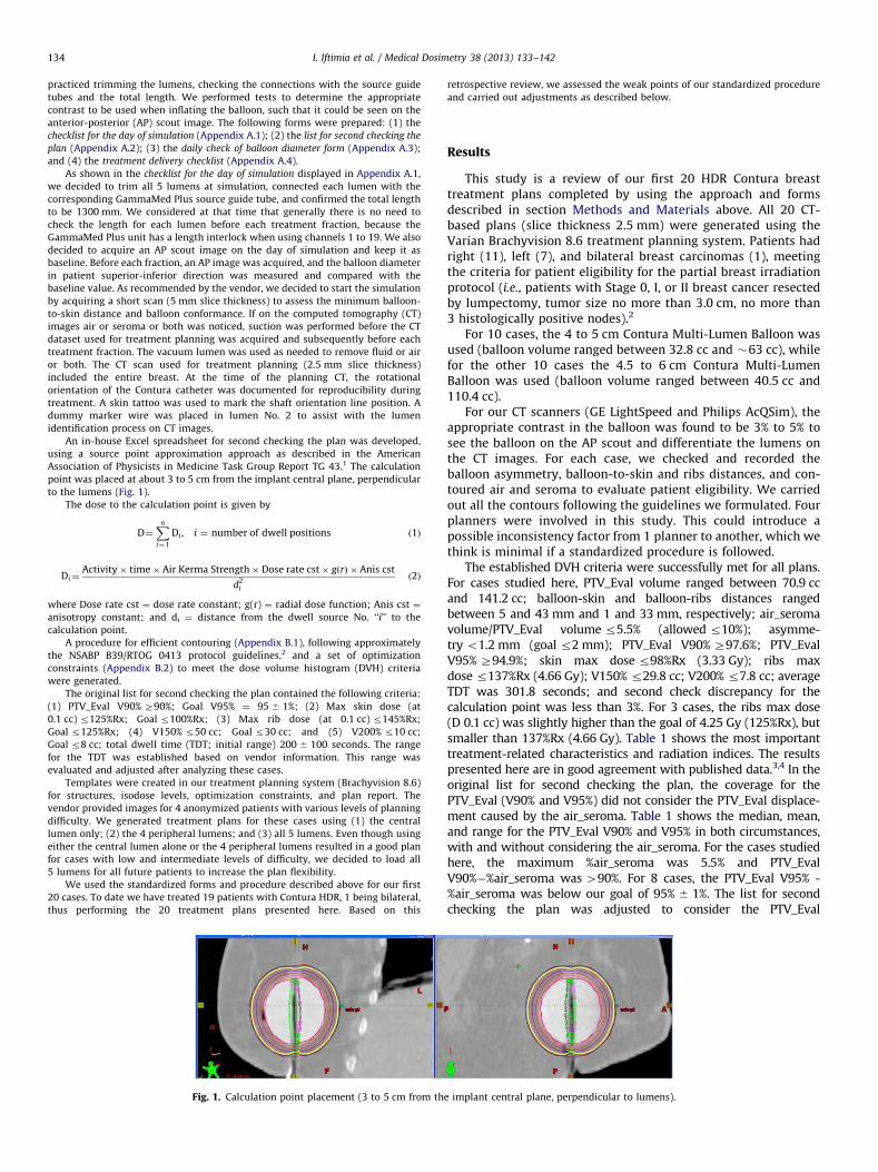
point was placed at about 3 to 5 cm from the implant central plane, perpendicular
to the lumens (Fig. 1).
The dose to the calculation point is given by
D¼Xn
i¼1
Di , i ¼ number of dwell positions ð1Þ
Di¼Activity� time� Air Kerma Strength� Dose rate cst� gðrÞ � Anis cst
d2i
ð2Þ
where Dose rate cst ¼ dose rate constant; g(r) ¼ radial dose function; Anis cst ¼
anisotropy constant; and di ¼ distance from the dwell source No. ‘‘i’’ to the
calculation point.
A procedure for efficient contouring (Appendix B.1), following approximately
the NSABP B39/RTOG 0413 protocol guidelines.2 and a set of optimization
constraints (Appendix B.2) to meet the dose volume histogram (DVH) criteria
were generated.
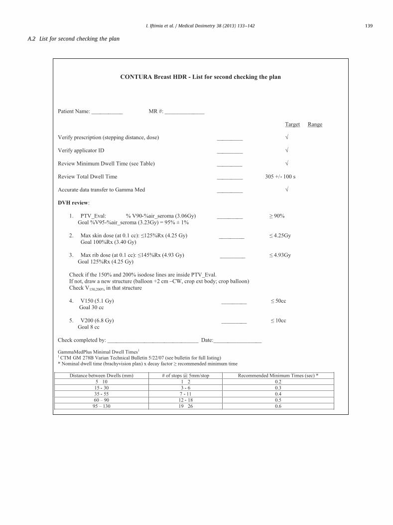
The original list for second checking the plan contained the following criteria:
(1) PTV_Eval V90% Z90%; Goal V95% ¼ 95 � 1%; (2) Max skin dose (at
0.1 cc) r125%Rx; Goal r100%Rx; (3) Max rib dose (at 0.1 cc) r145%Rx;
Goal r125%Rx; (4) V150% r50 cc; Goal r30 cc; and (5) V200% r10 cc;
Goal r8 cc; total dwell time (TDT; initial range) 200 � 100 seconds. The range
for the TDT was established based on vendor information. This range was
evaluated and adjusted after analyzing these cases.
Templates were created in our treatment planning system (Brachyvision 8.6)
for structures, isodose levels, optimization constraints, and plan report. The
vendor provided images for 4 anonymized patients with various levels of planning
difficulty. We generated treatment plans for these cases using (1) the central
lumen only; (2) the 4 peripheral lumens; and (3) all 5 lumens. Even though using
either the central lumen alone or the 4 peripheral lumens resulted in a good plan
for cases with low and intermediate levels of difficulty, we decided to load all
5 lumens for all future patients to increase the plan flexibility.
We used the standardized forms and procedure described above for our first
20 cases. To date we have treated 19 patients with Contura HDR, 1 being bilateral,
thus performing the 20 treatment plans presented here. Based on this
Fig. 1. Calculation point placement (3 to 5 cm from th
retrospective review, we assessed the weak points of our standardized procedure
and carried out adjustments as described below.
Results
This study is a review of our first 20 HDR Contura breasttreatment plans completed by using the approach and formsdescribed in section Methods and Materials above. All 20 CT-based plans (slice thickness 2.5 mm) were generated using theVarian Brachyvision 8.6 treatment planning system. Patients hadright (11), left (7), and bilateral breast carcinomas (1), meetingthe criteria for patient eligibility for the partial breast irradiationprotocol (i.e., patients with Stage 0, I, or II breast cancer resectedby lumpectomy, tumor size no more than 3.0 cm, no more than3 histologically positive nodes).2
For 10 cases, the 4 to 5 cm Contura Multi-Lumen Balloon wasused (balloon volume ranged between 32.8 cc and �63 cc), whilefor the other 10 cases the 4.5 to 6 cm Contura Multi-LumenBalloon was used (balloon volume ranged between 40.5 cc and110.4 cc).
For our CT scanners (GE LightSpeed and Philips AcQSim), theappropriate contrast in the balloon was found to be 3% to 5% tosee the balloon on the AP scout and differentiate the lumens onthe CT images. For each case, we checked and recorded theballoon asymmetry, balloon-to-skin and ribs distances, and con-toured air and seroma to evaluate patient eligibility. We carriedout all the contours following the guidelines we formulated. Fourplanners were involved in this study. This could introduce apossible inconsistency factor from 1 planner to another, which wethink is minimal if a standardized procedure is followed.
The established DVH criteria were successfully met for all plans.For cases studied here, PTV_Eval volume ranged between 70.9 ccand 141.2 cc; balloon-skin and balloon-ribs distances rangedbetween 5 and 43 mm and 1 and 33 mm, respectively; air_seromavolume/PTV_Eval volume r5.5% (allowed r10%); asymme-try o1.2 mm (goal r2 mm); PTV_Eval V90% Z97.6%; PTV_EvalV95% Z94.9%; skin max dose r98%Rx (3.33 Gy); ribs maxdose r137%Rx (4.66 Gy); V150% r29.8 cc; V200% r7.8 cc; averageTDT was 301.8 seconds; and second check discrepancy for thecalculation point was less than 3%. For 3 cases, the ribs max dose(D 0.1 cc) was slightly higher than the goal of 4.25 Gy (125%Rx), butsmaller than 137%Rx (4.66 Gy). Table 1 shows the most importanttreatment-related characteristics and radiation indices. The resultspresented here are in good agreement with published data.3,4 In theoriginal list for second checking the plan, the coverage for thePTV_Eval (V90% and V95%) did not consider the PTV_Eval displace-ment caused by the air_seroma. Table 1 shows the median, mean,and range for the PTV_Eval V90% and V95% in both circumstances,with and without considering the air_seroma. For the cases studiedhere, the maximum %air_seroma was 5.5% and PTV_EvalV90%�%air_seroma was 490%. For 8 cases, the PTV_Eval V95% -%air_seroma was below our goal of 95% � 1%. The list for secondchecking the plan was adjusted to consider the PTV_Eval
e implant central plane, perpendicular to lumens).
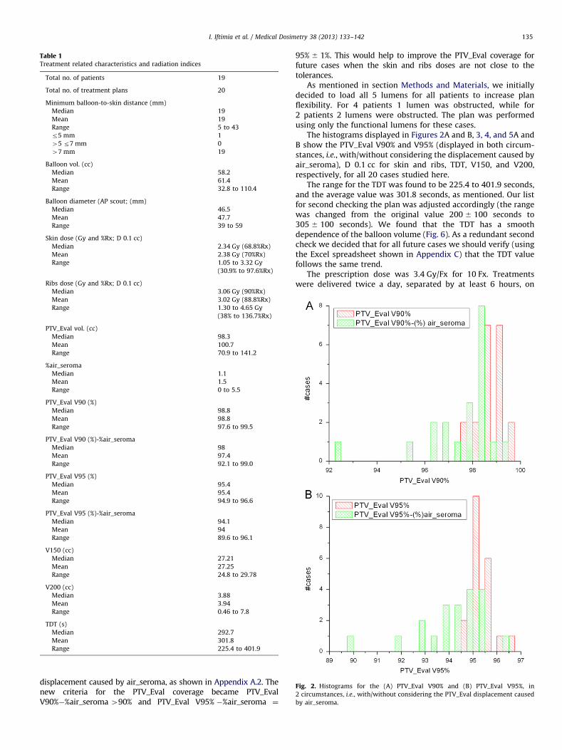
Table 1Treatment related characteristics and radiation indices
Total no. of patients 19
Total no. of treatment plans 20
Minimum balloon-to-skin distance (mm)
Median 19
Mean 19
Range 5 to 43
r5 mm 1
45 r7 mm 0
47 mm 19
Balloon vol. (cc)
Median 58.2
Mean 61.4
Range 32.8 to 110.4
Balloon diameter (AP scout; (mm)
Median 46.5
Mean 47.7
Range 39 to 59
Skin dose (Gy and %Rx; D 0.1 cc)
Median 2.34 Gy (68.8%Rx)
Mean 2.38 Gy (70%Rx)
Range 1.05 to 3.32 Gy
(30.9% to 97.6%Rx)
Ribs dose (Gy and %Rx; D 0.1 cc)
Median 3.06 Gy (90%Rx)
Mean 3.02 Gy (88.8%Rx)
Range 1.30 to 4.65 Gy
(38% to 136.7%Rx)
PTV_Eval vol. (cc)
Median 98.3
Mean 100.7
Range 70.9 to 141.2
%air_seroma
Median 1.1
Mean 1.5
Range 0 to 5.5
PTV_Eval V90 (%)
Median 98.8
Mean 98.8
Range 97.6 to 99.5
PTV_Eval V90 (%)-%air_seroma
Median 98
Mean 97.4
Range 92.1 to 99.0
PTV_Eval V95 (%)
Median 95.4
Mean 95.4
Range 94.9 to 96.6
PTV_Eval V95 (%)-%air_seroma
Median 94.1
Mean 94
Range 89.6 to 96.1
V150 (cc)
Median 27.21
Mean 27.25
Range 24.8 to 29.78
V200 (cc)
Median 3.88
Mean 3.94
Range 0.46 to 7.8
TDT (s)
Median 292.7
Mean 301.8
Range 225.4 to 401.9
Fig. 2. Histograms for the (A) PTV_Eval V90% and (B) PTV_Eval V95%, in
2 circumstances, i.e., with/without considering the PTV_Eval displacement caused
by air_seroma.
I. Iftimia et al. / Medical Dosimetry 38 (2013) 133–142 135
displacement caused by air_seroma, as shown in Appendix A.2. Thenew criteria for the PTV_Eval coverage became PTV_EvalV90%�%air_seroma 490% and PTV_Eval V95% �%air_seroma ¼
95% � 1%. This would help to improve the PTV_Eval coverage forfuture cases when the skin and ribs doses are not close to thetolerances.
As mentioned in section Methods and Materials, we initiallydecided to load all 5 lumens for all patients to increase planflexibility. For 4 patients 1 lumen was obstructed, while for2 patients 2 lumens were obstructed. The plan was performedusing only the functional lumens for these cases.
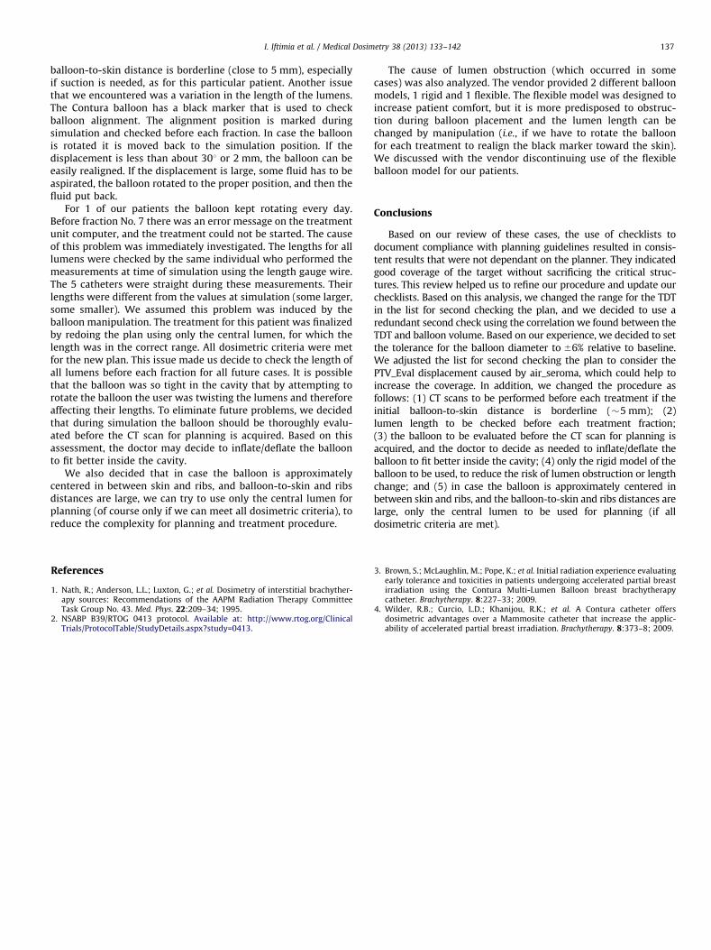
The histograms displayed in Figures 2A and B, 3, 4, and 5A andB show the PTV_Eval V90% and V95% (displayed in both circum-stances, i.e., with/without considering the displacement caused byair_seroma), D 0.1 cc for skin and ribs, TDT, V150, and V200,respectively, for all 20 cases studied here.
The range for the TDT was found to be 225.4 to 401.9 seconds,and the average value was 301.8 seconds, as mentioned. Our listfor second checking the plan was adjusted accordingly (the rangewas changed from the original value 200 � 100 seconds to305 � 100 seconds). We found that the TDT has a smoothdependence of the balloon volume (Fig. 6). As a redundant secondcheck we decided that for all future cases we should verify (usingthe Excel spreadsheet shown in Appendix C) that the TDT valuefollows the same trend.
The prescription dose was 3.4 Gy/Fx for 10 Fx. Treatmentswere delivered twice a day, separated by at least 6 hours, on
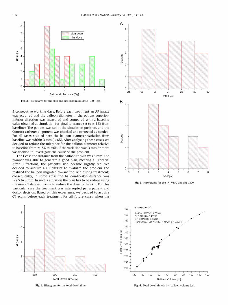
Fig. 3. Histograms for the skin and ribs maximum dose (D 0.1 cc).
Fig. 5. Histograms for the (A) V150 and (B) V200.
I. Iftimia et al. / Medical Dosimetry 38 (2013) 133–142136
5 consecutive working days. Before each treatment an AP imagewas acquired and the balloon diameter in the patient superior-inferior direction was measured and compared with a baselinevalue obtained at simulation (original tolerance set to � 15% frombaseline). The patient was set in the simulation position, and theContura catheter alignment was checked and corrected as needed.For all cases studied here the balloon diameter variation frombaseline was within 3 mm (o6%). After analyzing these cases wedecided to reduce the tolerance for the balloon diameter relativeto baseline from �15% to �6%. If the variation was 3 mm or morewe decided to investigate the cause of the problem.
For 1 case the distance from the balloon to skin was 5 mm. Theplanner was able to generate a good plan, meeting all criteria.After 8 fractions, the patient’s skin became slightly red. Wedecided to acquire a CT dataset to evaluate the problem andrealized the balloon migrated toward the skin during treatment;consequently, in some areas the balloon-to-skin distance was�2.5 to 3 mm. In such a situation the plan has to be redone usingthe new CT dataset, trying to reduce the dose to the skin. For thisparticular case the treatment was interrupted per a patient anddoctor decision. Based on this experience, we decided to acquireCT scans before each treatment for all future cases when the
Fig. 4. Histogram for the total dwell time. Fig. 6. Total dwell time [s] vs balloon volume [cc].
I. Iftimia et al. / Medical Dosimetry 38 (2013) 133–142 137
balloon-to-skin distance is borderline (close to 5 mm), especiallyif suction is needed, as for this particular patient. Another issuethat we encountered was a variation in the length of the lumens.The Contura balloon has a black marker that is used to checkballoon alignment. The alignment position is marked duringsimulation and checked before each fraction. In case the balloonis rotated it is moved back to the simulation position. If thedisplacement is less than about 301 or 2 mm, the balloon can beeasily realigned. If the displacement is large, some fluid has to beaspirated, the balloon rotated to the proper position, and then thefluid put back.
For 1 of our patients the balloon kept rotating every day.Before fraction No. 7 there was an error message on the treatmentunit computer, and the treatment could not be started. The causeof this problem was immediately investigated. The lengths for alllumens were checked by the same individual who performed themeasurements at time of simulation using the length gauge wire.The 5 catheters were straight during these measurements. Theirlengths were different from the values at simulation (some larger,some smaller). We assumed this problem was induced by theballoon manipulation. The treatment for this patient was finalizedby redoing the plan using only the central lumen, for which thelength was in the correct range. All dosimetric criteria were metfor the new plan. This issue made us decide to check the length ofall lumens before each fraction for all future cases. It is possiblethat the balloon was so tight in the cavity that by attempting torotate the balloon the user was twisting the lumens and thereforeaffecting their lengths. To eliminate future problems, we decidedthat during simulation the balloon should be thoroughly evalu-ated before the CT scan for planning is acquired. Based on thisassessment, the doctor may decide to inflate/deflate the balloonto fit better inside the cavity.
We also decided that in case the balloon is approximatelycentered in between skin and ribs, and balloon-to-skin and ribsdistances are large, we can try to use only the central lumen forplanning (of course only if we can meet all dosimetric criteria), toreduce the complexity for planning and treatment procedure.
The cause of lumen obstruction (which occurred in somecases) was also analyzed. The vendor provided 2 different balloonmodels, 1 rigid and 1 flexible. The flexible model was designed toincrease patient comfort, but it is more predisposed to obstruc-tion during balloon placement and the lumen length can bechanged by manipulation (i.e., if we have to rotate the balloonfor each treatment to realign the black marker toward the skin).We discussed with the vendor discontinuing use of the flexibleballoon model for our patients.
Conclusions
Based on our review of these cases, the use of checklists todocument compliance with planning guidelines resulted in consis-tent results that were not dependant on the planner. They indicatedgood coverage of the target without sacrificing the critical struc-tures. This review helped us to refine our procedure and update ourchecklists. Based on this analysis, we changed the range for the TDTin the list for second checking the plan, and we decided to use aredundant second check using the correlation we found between theTDT and balloon volume. Based on our experience, we decided to setthe tolerance for the balloon diameter to �6% relative to baseline.We adjusted the list for second checking the plan to consider thePTV_Eval displacement caused by air_seroma, which could help toincrease the coverage. In addition, we changed the procedure asfollows: (1) CT scans to be performed before each treatment if theinitial balloon-to-skin distance is borderline (�5 mm); (2)lumen length to be checked before each treatment fraction;(3) the balloon to be evaluated before the CT scan for planning isacquired, and the doctor to decide as needed to inflate/deflate theballoon to fit better inside the cavity; (4) only the rigid model of theballoon to be used, to reduce the risk of lumen obstruction or lengthchange; and (5) in case the balloon is approximately centered inbetween skin and ribs, and the balloon-to-skin and ribs distances arelarge, only the central lumen to be used for planning (if alldosimetric criteria are met).
References
1. Nath, R.; Anderson, L.L.; Luxton, G.; et al. Dosimetry of interstitial brachyther-apy sources: Recommendations of the AAPM Radiation Therapy CommitteeTask Group No. 43. Med. Phys. 22:209–34; 1995.
2. NSABP B39/RTOG 0413 protocol. Available at: http://www.rtog.org/ClinicalTrials/ProtocolTable/StudyDetails.aspx?study=0413.
3. Brown, S.; McLaughlin, M.; Pope, K.; et al. Initial radiation experience evaluatingearly tolerance and toxicities in patients undergoing accelerated partial breastirradiation using the Contura Multi-Lumen Balloon breast brachytherapycatheter. Brachytherapy. 8:227–33; 2009.
4. Wilder, R.B.; Curcio, L.D.; Khanijou, R.K.; et al. A Contura catheter offersdosimetric advantages over a Mammosite catheter that increase the applic-ability of accelerated partial breast irradiation. Brachytherapy. 8:373–8; 2009.
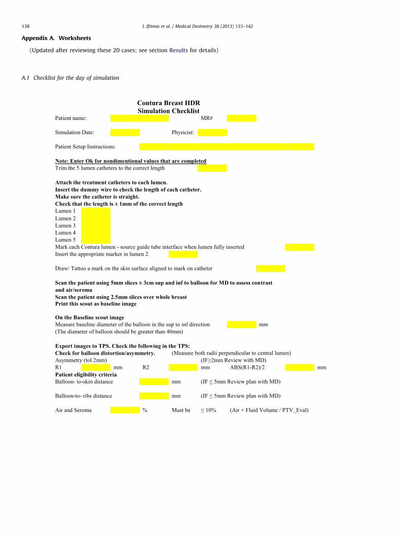
Appendix A. Worksheets
(Updated after reviewing these 20 cases; see section Results for details)
A.1 Checklist for the day of simulation
I. Iftimia et al. / Medical Dosimetry 38 (2013) 133–142138
A.2 List for second checking the plan
I. Iftimia et al. / Medical Dosimetry 38 (2013) 133–142 139
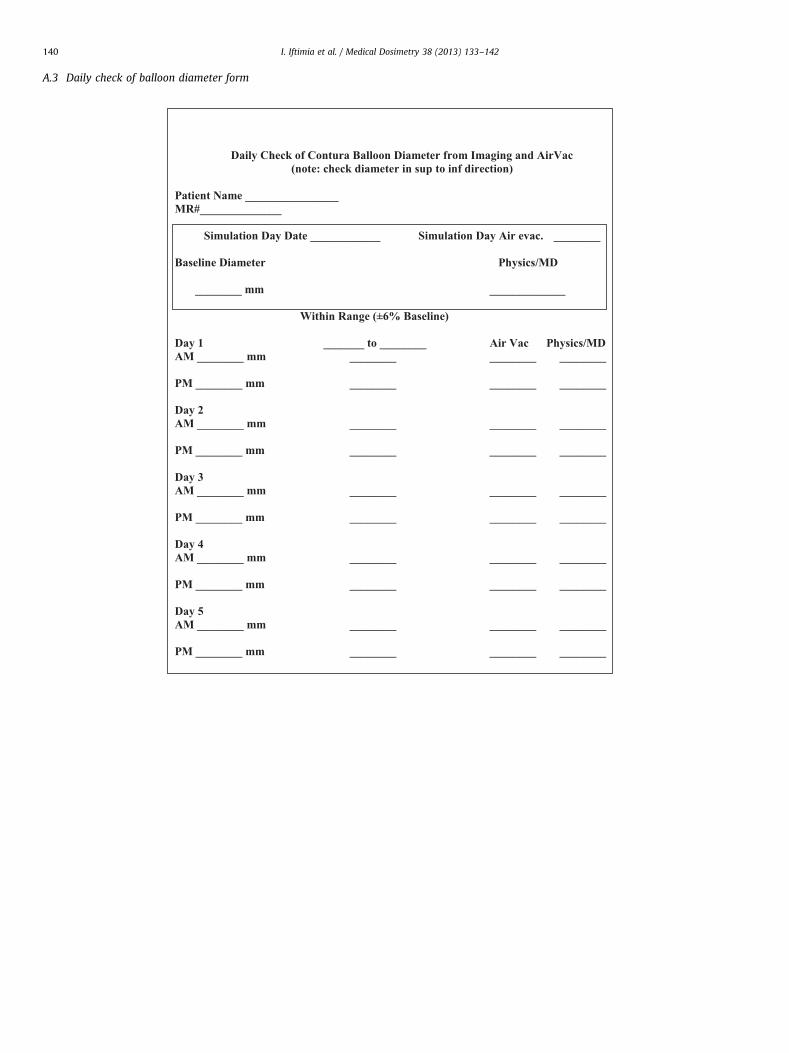
A.3 Daily check of balloon diameter form
I. Iftimia et al. / Medical Dosimetry 38 (2013) 133–142140

A.4 Treatment delivery checklist
HDR Treatment Checklist
1. Patient Name:Date:
MR#:
MD Physicist
2. QA Performed N/A
3. Patient Consent N/A
4. Prior to treatment, MD to obtain patient verification
N/A
Patient Gives Name [required]
N/A
and Patient gives date of birth [Out Patients]
N/A
or Wrist band identification [In Patients]
N/A
5. Pre treatment patient survey
N/A
Meter model and S/N:
Background Reading mR/hr
Patient Reading mR/hr
6. AP scout film reviewed N/A
7. Contura Checks
7.a Verify balloon alignment with skin mark
or
7.b Check diameter from CT within 6% of Baseline
N/A
7.c Verify correct lumens and catheter connections
or
8. Prescription N/A
9. Treatment Plan Done N/A
10. Independent Plan Verification
N/A
11. Plan Approved by MD N/A
12. Treatment Parameters on Display Checked
N/A
13. "Time-out:" and
Verify all items 1-12 done
Verify on GammaMed Treatment PC: patient
name, Fx # and total Dwell Time
14. Physicist Present During Treatment
N/A
15. MD Present During Treatment
N/A
16. Post treatment surveys N/A
Meter model and S/N:
Background Reading mR/hr
Patient Reading mR/hr
Area Reading mR/hr
17. MD Review of Treatment Summary
N/A
I. Iftimia et al. / Medical Dosimetry 38 (2013) 133–142 141
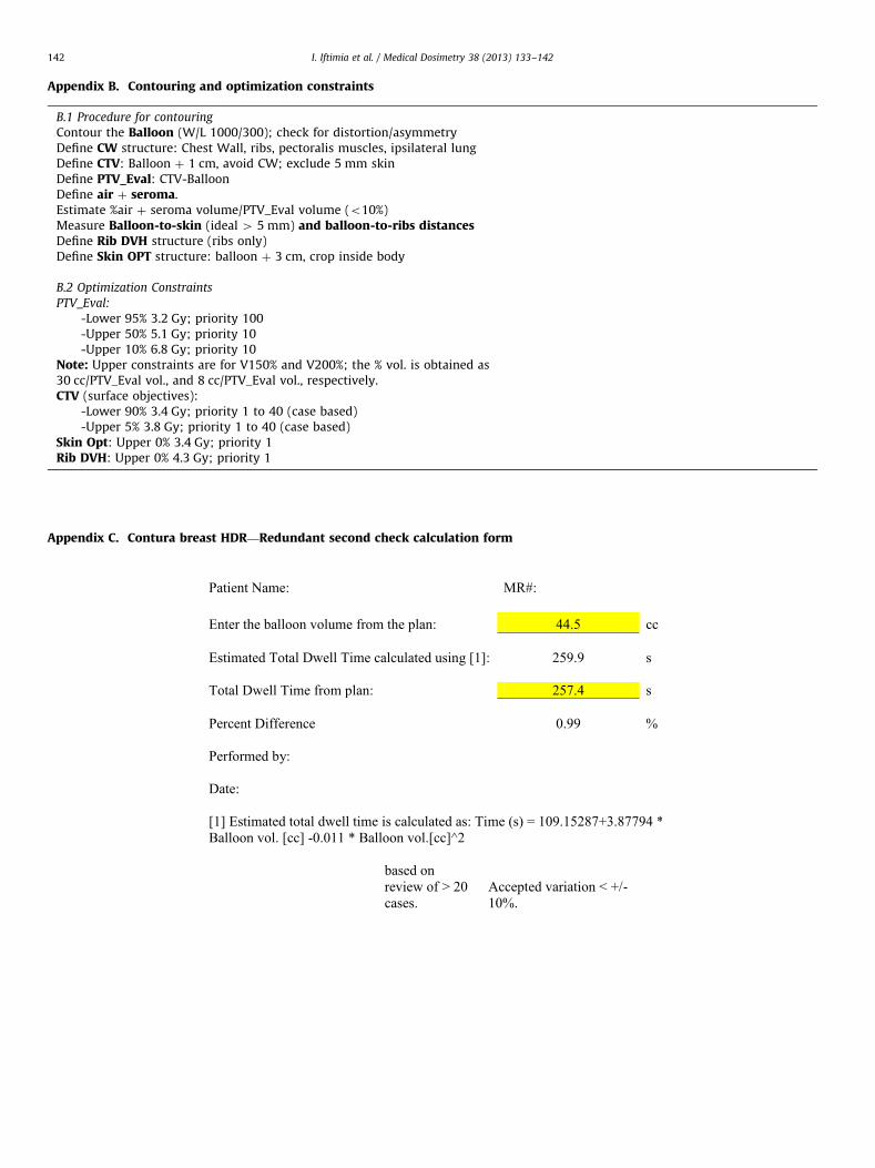
Appendix B. Contouring and optimization constraints
B.1 Procedure for contouring
Contour the Balloon (W/L 1000/300); check for distortion/asymmetryDefine CW structure: Chest Wall, ribs, pectoralis muscles, ipsilateral lungDefine CTV: Balloon þ 1 cm, avoid CW; exclude 5 mm skinDefine PTV_Eval: CTV-BalloonDefine air þ seroma.Estimate %air þ seroma volume/PTV_Eval volume (o10%)Measure Balloon-to-skin (ideal 4 5 mm) and balloon-to-ribs distancesDefine Rib DVH structure (ribs only)Define Skin OPT structure: balloon þ 3 cm, crop inside body
B.2 Optimization Constraints
PTV_Eval:
-Lower 95% 3.2 Gy; priority 100-Upper 50% 5.1 Gy; priority 10-Upper 10% 6.8 Gy; priority 10
Note: Upper constraints are for V150% and V200%; the % vol. is obtained as30 cc/PTV_Eval vol., and 8 cc/PTV_Eval vol., respectively.CTV (surface objectives):
-Lower 90% 3.4 Gy; priority 1 to 40 (case based)-Upper 5% 3.8 Gy; priority 1 to 40 (case based)
Skin Opt: Upper 0% 3.4 Gy; priority 1Rib DVH: Upper 0% 4.3 Gy; priority 1
Appendix C. Contura breast HDR—Redundant second check calculation form
I. Iftimia et al. / Medical Dosimetry 38 (2013) 133–142142