Embed Size (px)
Citation preview
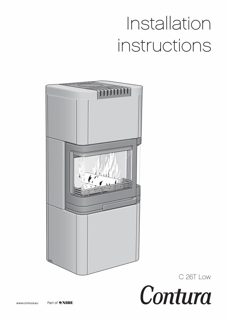
Installation instructions
C 26T Low
www.contura.eu
NIBE AB · Box 134 · 285 23 Markaryd · Suèdewww.contura.eu

GB
50 CERTIFICATE
PRODUCTProduct type Stove lit with solid biofuels Type designation Contura 26T Manufacturing number See rating plate on the stove Intended area of use Heating of rooms in residential buildings Fuel Wood
MANUFACTURERName NIBE AB / Contura Address Box 134, Skulptörvägen 10 SE-285 23 Markaryd, Sweden
CHECKSAccording to AVCP System 3 European standard EN 13240:2001 / A2:2004 Test institute Rein-Ruhr Feuerstätten Prüfstelle, NB 1625, has checked declared performance and issued test report no. RRF-40 08 1853
PERFORMANCE DECLARATIONNo. C26T-CPR-130617-SE-1
DECLARED PERFORMANCE
Essential characteristics Performance Harmonised technicalspecification
Reaction to fire A1 WT
Minimum distance to combustible material 100 mm to rear600 mm to side Other safety distances according to the installation instructions
Risk of falling embers Approved
Emissions from combustion CO 0.09% NOx 82 mg/m3 OGC 43 mg/m3 PM 22 mg/m3
Surface temperatures Approved
Cleaning options Approved
Mechanical durability Approved
Emissions of hazardous substances Approved
Nominal output 6 kW
Efficiency 79%
Flue gas temperature in connector at nominal output
280°C
EN 13240:2001 / A2:2004
The undersigned is responsible for the manufacture and conformity with the declared performance.
Niklas Gunnarsson, Business area manager NIBE STOVES Markaryd, 1st July 2013

GB
51
List of Contents
Technical details 52
Supply of combustion air 53
Connection to chimney 54
Installation distances 55
Installation of C26T High 56
A warm welcome to Contura.
A warm welcome to the Contura family. We hope you
will get a great deal of pleasure from your new stove.
As a new owner of a Contura stove, you have secured
a product with timeless design and long service life.
Contura also has a combustion process that is both
environmentally friendly and efficient, for the best heat
production.
Read through these installation instructions carefully
before installation. Read how to best light your stove
in the lighting instructions.
The stove becomes very hotDuring operation, certain surfaces of the stove become very hot and can cause burn injuries if touched. Also, take heed of the strong heat radiated through the door glass. Placing flammable material closer than the safe distance indicated may cause a fire. Smoulder combustion can cause quick gas ignition with the risk of damage to property and personal injury.
NOTE! WARNING! Report the installation of a stove to your local authority.The owner of the house is personally responsible for ensuring compliance with the mandatory safety requirements and must have the installation approved by a qualified inspector. Your local chimney sweep must also be informed about the installation, as this will affect the routines for regular chimney-sweeping services.
CONTENTS
GB
52 FACTS
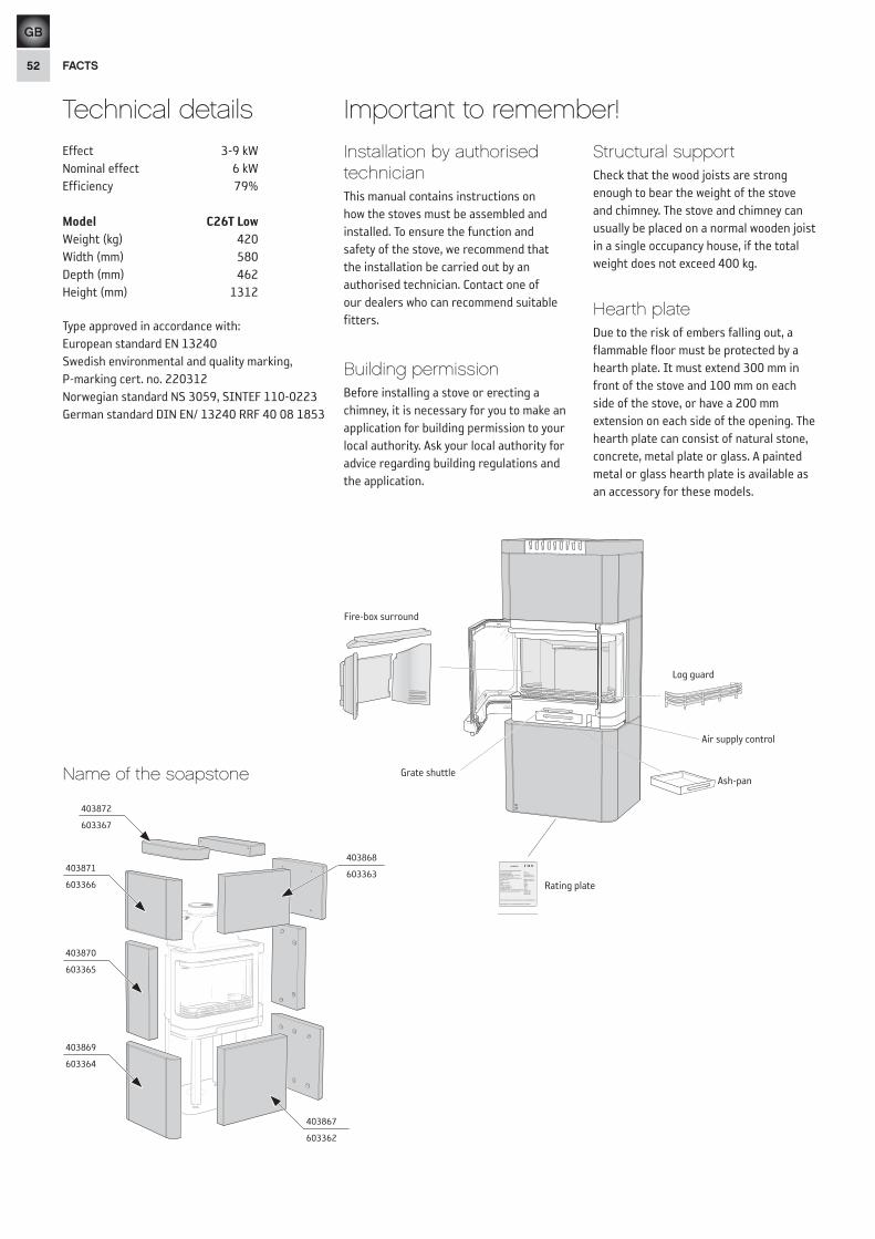
Effect 3-9 kWNominal effect 6 kWEfficiency 79%
Model C26T Low Weight (kg) 420Width (mm) 580Depth (mm) 462Height (mm) 1312
Type approved in accordance with:European standard EN 13240Swedish environmental and quality marking,P-marking cert. no. 220312Norwegian standard NS 3059, SINTEF 110-0223German standard DIN EN/ 13240 RRF 40 08 1853
Installation by authorised technician This manual contains instructions on how the stoves must be assembled and installed. To ensure the function and safety of the stove, we recommend that the installation be carried out by an authorised technician. Contact one of our dealers who can recommend suitable fitters.
Building permissionBefore installing a stove or erecting a chimney, it is necessary for you to make an application for building permission to your local authority. Ask your local authority for advice regarding building regulations and the application.
Structural supportCheck that the wood joists are strong enough to bear the weight of the stove and chimney. The stove and chimney can usually be placed on a normal wooden joist in a single occupancy house, if the total weight does not exceed 400 kg.
Hearth plateDue to the risk of embers falling out, a flammable floor must be protected by a hearth plate. It must extend 300 mm in front of the stove and 100 mm on each side of the stove, or have a 200 mm extension on each side of the opening. The hearth plate can consist of natural stone, concrete, metal plate or glass. A painted metal or glass hearth plate is available as an accessory for these models.
Important to remember!Technical details
Name of the soapstone
403872
403871
403870
403867
403868
403869
603367
603366
603365
603362
603363
603364
Eldstadsbeklädnad
Rosterreglage Asklåda
Förbränningsluftsreglage
Brasbegränsare
HANDÖL
In accordance with standards belowmarking was affixed:European Standard:SE Quality Certification, P-marked:NO Standard NS 3059:DE and AT Standard DIN 18.891 andArt 15a B-VG:Type:Nominal Output:Fuel:Minimun draught:Flue gas temerature:Energy efficiency:Emission of CO in cumbustion products:Distance to cumbustible wall (mm):
Follow the user’s instructions and use only recomended fuel
NIBE AB Box 134 SE-285 23 MARKARYD SWEDEN
2007EN 13240Cert no 0112/07SINTEF 110-0275
RRF-40 07 13 90Handöl 31/31A/32/32A
5 kWWood12 Pa280°C78%0,14%Behind 150Beside 450 Corner 150
HANDÖL
NIBE AB SE-85 21 Markaryd Sweden
Type:Production no.
50-series7090300236
Rating plate
Log guard
Fire-box surround
Ash-panGrate shuttle
Air supply control
GB
53
HK HK
HK
HK
30 m
m
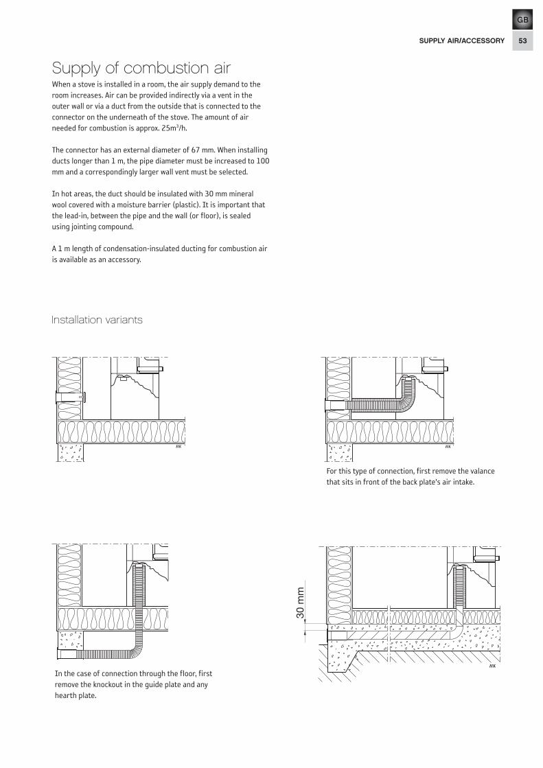
For this type of connection, first remove the valance that sits in front of the back plate's air intake.
In the case of connection through the floor, first remove the knockout in the guide plate and any hearth plate.
SUPPLY AIR/ACCESSORY
Supply of combustion airWhen a stove is installed in a room, the air supply demand to the room increases. Air can be provided indirectly via a vent in the outer wall or via a duct from the outside that is connected to the connector on the underneath of the stove. The amount of air needed for combustion is approx. 25m3/h.
The connector has an external diameter of 67 mm. When installing ducts longer than 1 m, the pipe diameter must be increased to 100 mm and a correspondingly larger wall vent must be selected.
In hot areas, the duct should be insulated with 30 mm mineral wool covered with a moisture barrier (plastic). It is important that the lead-in, between the pipe and the wall (or floor), is sealed using jointing compound.
A 1 m length of condensation-insulated ducting for combustion air is available as an accessory.
Installation variants

GB
54 CHIMNEY
Connection to chimney
Ø ca 180 mmØ ca 180 mm
Rear connection to a masonry chimney
Top connection to the chimney
Make sure that the connector gasket does not come loose when the connection pipe is placed on the sleeve. If further sealing material is required, heat-resistant sealant may be used.
The back panel must be installed before the stove is connected at the rear.
The hot air grille must be installed before the chimney is connected to the top.
• The stove meets the requirements for connecting to chimneys dimensioned for flue gas temperatures of 350°C.
• The external diameter of the connection sleeve is 150 mm.
• The stove requires a draft in the chimney of at least –12 Pa. The draft is affected both by the length and area of the chimney, and by how well sealed it is. The minimum recommended chimney length is 3.5 m and suitable cross sectional area is 150-200 cm² (140-160 mm in diameter).
• A flue with sharp bends and horizontal routing reduces the draught in the chimney. The maximum horizontal flue is 1 m, on the condition that the vertical flue length is at least 5 m.
• It must be possible to sweep the full length of the flue and the soot doors must be easily accessible.
• Carefully check that the chimney is sealed and that there is no leakage around soot doors and flue connections.
2 31
5 64
!
SweepingWhen sweeping, the smoke baffle must be removed; on the Contura 20 series this is easily done by lifting and then pushing the baffle to the side.
In the bag with these installation instructionsare two wing screws for the cover.

GB
55INSTALLATION DISTANCES
C26T Low
Installation distances
442
E 150
A 1
116
B 1
033
F 41
0
C 188
D 85
Utv Ø150
502
462
1312
582
23
00
G 90
Combustible roof
Combustion air hose(accessory)
*To prevent discolouration of painted fire walls, we recommend the same side distance as to combustible walls.
A = height from floor to chimney connection upwards
B = height from floor to c/c chimney connection rear
C = distance from back to c/c chimney connection upwards
D = distance from back to chimney connection rear
E = distance from back to hole in guide plate
F = height from floor to air inlet connector (410 mm)
G = distance to hole in guide plate
288
100
600
890
500
400
300
200
300
400
500
200
Combustible wall
Permitted area forcombustible material
435
120
890
810
Combustible wall
238
50
300*
590
Fire-retardant wall ofbrick or concrete
3655
0
795
740
Fire-retardant wall ofbrick or concrete
Place the stove on the hearth plate and check that the installation distances are not less than those that are given in the figures below. The minimum distance in front of the stove opening to combustible parts of the building or interior decoration must be at least 1 m.
When top connecting a steel flue, please refer to the particular manufacturer's installation instructions. Observe the safety distance to combustible material that the steel flue requires.
GB
56 INSTALLATION
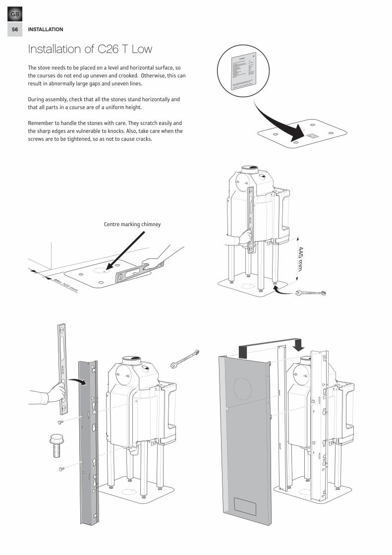
Installation of C26 T Low
Min 105 mm
445 mm
13 13VANADI UMNo. 7 CHROME
Centre marking chimney
10
10
VANADIUM
No. 7CHROME
The stove needs to be placed on a level and horizontal surface, so the courses do not end up uneven and crooked. Otherwise, this can result in abnormally large gaps and uneven lines.
During assembly, check that all the stones stand horizontally and that all parts in a course are of a uniform height.
Remember to handle the stones with care. They scratch easily and the sharp edges are vulnerable to knocks. Also, take care when the screws are to be tightened, so as not to cause cracks.
GB
57INSTALLATION
5 m
m10
10
VANADIUM
No. 7CHROME
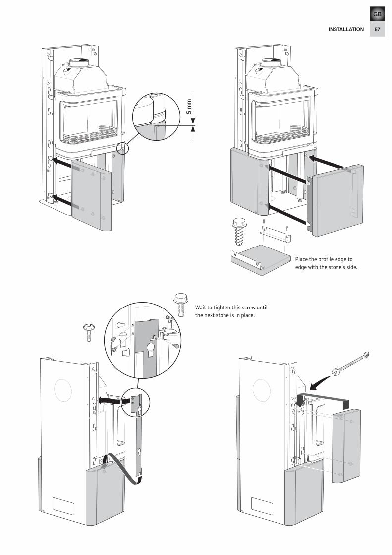
Wait to tighten this screw until the next stone is in place.
Place the profile edge to edge with the stone's side.

GB
58 INSTALLATION
Press the profiles up as far as they go, while tightening the screws.
!
10
10
VANADIUM
No. 7CHROME
10
10
VANADIUM
No. 7CHROME
Final inspection of the installation
It is extremely important that the installation is inspected by an authorised chimney sweep before the stove is used. Also read the ”Lighting instructions”, before lighting for the first time.
GB
59INSTALLATION
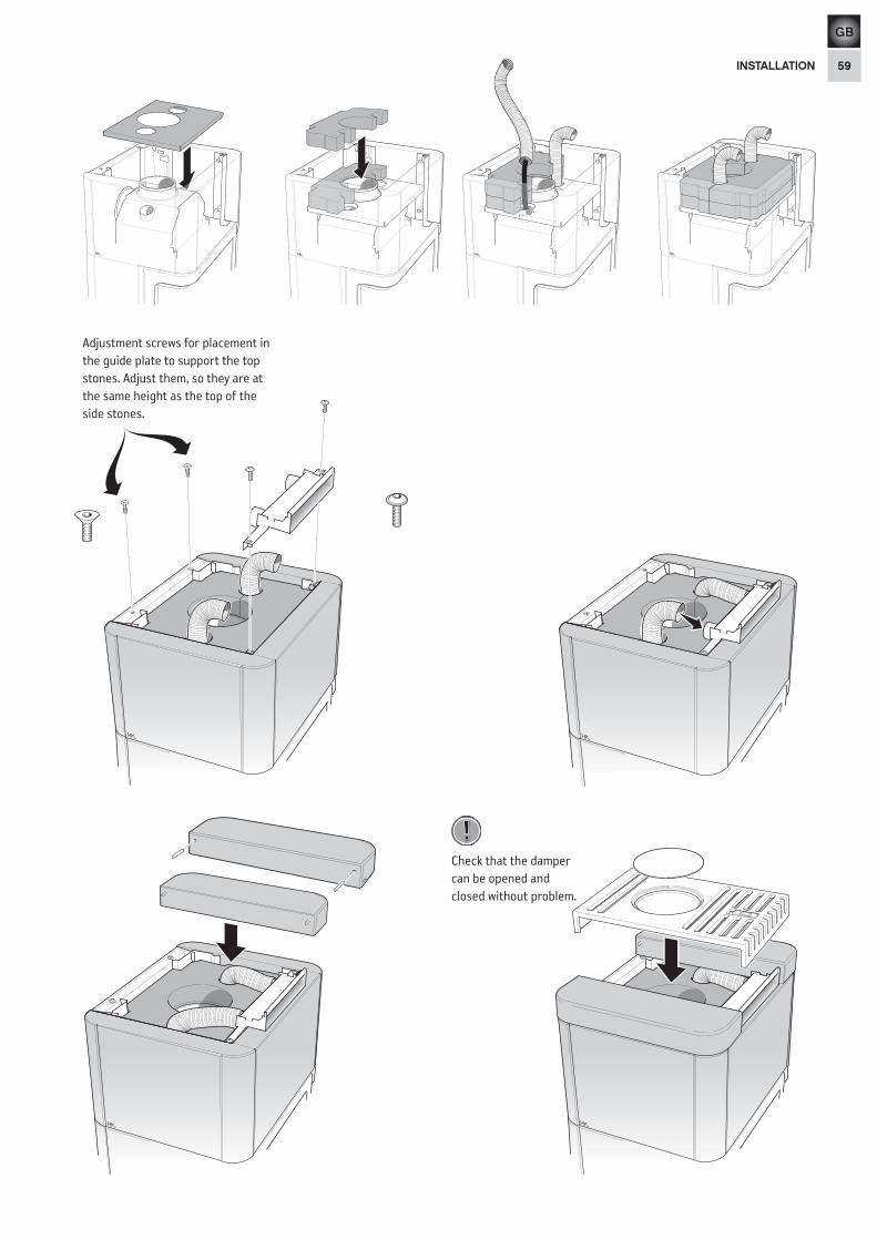
Adjustment screws for placement in the guide plate to support the top stones. Adjust them, so they are at the same height as the top of the side stones.
Check that the damper can be opened and closed without problem.
!

811091 IAV SE-EX C26T Low -42013-11-13
NIBE AB · Box 134 · SE-285 23 Markaryd · Swedenwww.contura.eu
Contura reserves the right to change dimensions and procedures described in these instructions at any time without special notice. The current edition can be downloaded from www.contura.eu