Embed Size (px)
Citation preview
Response of RC Structure Exposed to Explosion
Ankur Yadav1 1P.G. Student, Mewar University,
Chittorgarh, Rajasthan, India
Abstract - The purpose of buildings extends beyond merely
providing habitat to people. Buildings should be designed in a
manner which ensures security of their occupants. Hence, it is
important to study the effects that last loads can have on buildings.
Blast loads are dynamic in nature just like wind and earthquake
loads. This study focuses mainly on analyzing the effects of blast
loads on four different cases of structural systems and finding
ways to reduce these effects using methods like shear wall and steel
bracing with the help of ETAB 2015. It was concluded that the
provision of a shear wall around the structure contributes highly
in resisting blast loads, as compared to the other alternatives
under discussion.
1. INTRODUCTION
The purpose of buildings extends beyond merely providing
habitat to people. Buildings should be designed in a manner
which ensures security of their occupants. With structurally
more secure buildings, people will feel more protected against
unfortunate events such as acts of terrorism, etc. Hence, it is
important to study the effects that blast loads can have on
buildings. Blast loads are dynamic in nature, and can be
calculated precisely, just like wind and earthquake loads.
The foremost aim of this work is to discuss and analyze the
performance of different structural systems under the impact of
blast loads in events of explosions. The method for mitigating
effects of detonation has been discusses, thus preventing harm
to life, property and equipment. Relevant literature has been
studied thoroughly, with emphasis on topics like possibility of
vulnerability evaluation, risk easing, developing ductility and
structural response characteristics, etc.
1.1 Characteristics of Blast and its Effect on Structures
Energy discharge from an explosion is characterized as a
combination of air pressure and an audible blast. The energy so
released is divided into two phenomena. The first is thermal
radiation. The second is a pair of air and ground reactions,
known as air blast accompanied by ground shock. The principal
cause of damage to a building exposed to blast load is air blast.
Ground shock, on the other hand, propagates by compressing
the air molecules in its path producing the ambient overpressure
or the incident pressure (Bangash and Bangash, 2006).
The sequence of events that take place when a high explosive
material is initiated was explained by Smith and Hetherington
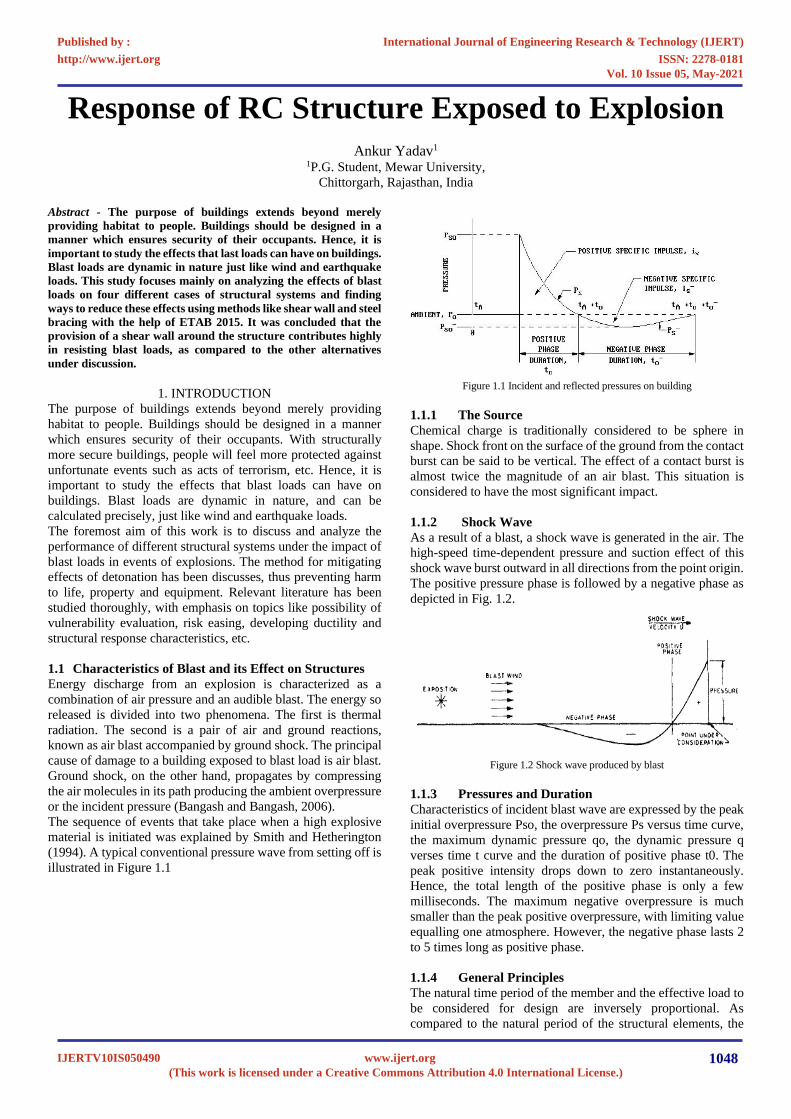
(1994). A typical conventional pressure wave from setting off is
illustrated in Figure 1.1
Figure 1.1 Incident and reflected pressures on building
1.1.1 The Source
Chemical charge is traditionally considered to be sphere in
shape. Shock front on the surface of the ground from the contact
burst can be said to be vertical. The effect of a contact burst is
almost twice the magnitude of an air blast. This situation is
considered to have the most significant impact.
1.1.2 Shock Wave
As a result of a blast, a shock wave is generated in the air. The
high-speed time-dependent pressure and suction effect of this
shock wave burst outward in all directions from the point origin.
The positive pressure phase is followed by a negative phase as
depicted in Fig. 1.2.
Figure 1.2 Shock wave produced by blast
1.1.3 Pressures and Duration
Characteristics of incident blast wave are expressed by the peak
initial overpressure Pso, the overpressure Ps versus time curve,
the maximum dynamic pressure qo, the dynamic pressure q
verses time t curve and the duration of positive phase t0. The
peak positive intensity drops down to zero instantaneously.
Hence, the total length of the positive phase is only a few
milliseconds. The maximum negative overpressure is much
smaller than the peak positive overpressure, with limiting value
equalling one atmosphere. However, the negative phase lasts 2
to 5 times long as positive phase.
1.1.4 General Principles
The natural time period of the member and the effective load to
be considered for design are inversely proportional. As
compared to the natural period of the structural elements, the
International Journal of Engineering Research & Technology (IJERT)
ISSN: 2278-0181http://www.ijert.org
IJERTV10IS050490(This work is licensed under a Creative Commons Attribution 4.0 International License.)
Published by :
www.ijert.org
Vol. 10 Issue 05, May-2021
1048

duration of positive phase of blast is generally small. Hence, this
may be treated as an impulse dilemma. As it is impossible to
predict the direction of a future explosion, every face of the
structure will be considered as a front face. Also, when the blast
field surrounds the structure, the difference of pressures on front
and rear faces tends to tilt and turn over the structure as a whole.
1.1.5 Scaling laws
The distance of the explosion point from the structure under
consideration is one of the most significant parameters for blast
loading computations. The peak pressure value and velocity of
the blast wave reduce sharply on increase of distance between
the blast source and the target surface, as illustrated in the Fig.3.
The figure shows how the positive phases of the blast waves are
longer in duration whenever the distance from the explosion
point increases.
Figure 1.3 Influence of distance on the blast positive pressure phase.
According to Hopkinson-Cranz law, a dimensional scaled
distance is introduced as described by the following equation:
Z = 𝑅
∛𝑊
Where, R is the distance from the explosion source to the point
of interest [m] and W is the weight (more precisely: the mass)
of the explosive [kg].
2. LITERATURE REVIEW
Mohammed Ettouney (1996) (ref. 4), conducted a study on
blast resistant design of commercial buildings. This paper
describes design modifications that might limit the occupant’s
exposure to extreme blast pressures and provides details that
improve ductility and structural response characteristics. And he
suggested that use of well-distributed lateral-load resisting
method in the horizontal floor plan and adding more shear walls
is not architecturally practical, a joint lateral-load resisting
mechanism can also be used.
Theodor Krauthammer (1999) (ref. 7) conducted series of
numerical studies on the behaviour of structural concrete and
structural steel connection subjected to blast loads. These
studies slowly improved the understanding of the role that
structural details play in affecting the behaviour. The result from
these investigations showed that structural details are important
for insuring the safety of blast resisting structures and the issues
of material models and strain-rate effects were addressed.
B.M. Luccioni, R.D. Ambrosini, and R.F. Danesi (2003) (ref.
11) conducted study on the analysis of the structural failure of a
reinforced concrete building caused by a blast load. All the
process from the explosion of the explosive charge to the
complete destruction, including the proliferation of the blast
wave and its interaction with the structure is reproduced. The
problem analyzed corresponds to an actual building that has
suffered a terrorist attack. The paper includes comparisons with
photographs of the real damage created by the explosive charge
that validates all the simulation procedure.
Larry C. Muszynski and Michael R. Purcell (2003) (ref. 9)
and conducted an investigative study on composite
reinforcement to strengthen existing concrete structures against
air blast. The results of these tests were considered successful,
considering the fact that the externally reinforced walls suffered
high displacements, yet did not fail. The pressure and impulse
data show that both structures would have failed disastrously
without the externally applied composite reinforcing materials.
The test of external reinforcement of concrete as a retrofit was
successful. The failure of the carbon-fiber laminate and E-glass
reinforced columns was perhaps caused by the wall acting as a
pusher plate against the columns. The carbon-fiber laminate
reinforcement might have performed better if it was used in a
continuous sheet rather than strips.
Marjanishvili, S. M. (2004) (ref. 12) present four successively
more complicated analysis procedures for evaluating the
progressive collapse hazard: linear-elastic static; nonlinear
static; linear-elastic dynamic and nonlinear dynamic. And
conclude that the most effective analysis method for progressive
collapse evaluation utilizes the useful parts of all four
procedures by systematically applying increasingly
comprehensive analysis procedures to confirm that the
possibility of progressive collapse is high. And he suggested
that, in order to establish the likelihood of progressive collapse,
a progressive analysis process be used. In progressive analysis,
a structure’s response is evaluated by starting with simpler static
methodology and then by moving on to increasingly complex
analysis methods as required, until it is determined that the
chance of progressive collapse is low or until all available
engineering methodologies are carried out.
T. Ngo, P. Mendis, A. Gupta & J. Ramsay (2007) (ref. 13)
described an overview of Blast Loading and Blast Effects on
Structures, This paper presents a complete overview of the
effects of explosion on structures. A justification of the nature
of explosions and the mechanism of blast waves in free air is
given. This paper also introduces different methodologies to
estimate blast loads and structural response. It is recommended
that guidelines on abnormal load cases and provisions on
progressive collapse prevention should be incorporated in the
current Building Regulations and Design Standards.
Requirements on ductility levels also help improve the building
performance under severe load conditions.
Zeynep Koccaz, Fatih Sutcuand and Necdet Torunbalci
(2008) (ref. 14) conducted study on essential techniques for
increasing the capacity of a building to provide defense against
explosive effects is discussed both with an architectural and
structural approach. And they concluded that with correct
choice of the structural system, well designed beam-column
connections, and structural elements designed adequately,
moment frames that transfer sufficient load and high quality
material; it is possible to build a blast resistant building.
Hrvoje Draganić, and Vladimir Sigmund (2012) (ref. 15)
conducted a study on the process of determining the blast load
on structures, explored the available literature on blast loads and
International Journal of Engineering Research & Technology (IJERT)
ISSN: 2278-0181http://www.ijert.org
IJERTV10IS050490(This work is licensed under a Creative Commons Attribution 4.0 International License.)
Published by :
www.ijert.org
Vol. 10 Issue 05, May-2021
1049

provides a numerical example of a fictive structure exposed to
this load. The blast load was analytically determined as a
pressure-time history and numerical model of the structure was
developed in SAP2000. The results confirm the initial
hypothesis that it is possible with conventional software to
simulate an explosion effects and give a preliminary evaluation
of the structure.
Vasilis Karlos and George Solomos (2013) (ref. 16) from the
European Laboratory for Structural Assessment carried out a
study on Calculation of the external explosion loads to be
considered in the blast protection design of a structure.
Empirical methods for the prediction of blast loads have been
selected as this is closer to the traditional engineering design
approach. Technical information has been collected, adapted
and presented in this study for the calculation of the external
explosion loads to be considered in the blast protection design
of a structure.
Priyanka A and Rajeeva S.V (2013) (ref. 17) present the
dynamic response of a High Rise Structure subjected to blast
load. The fundamentals of blast hazards and the interaction of
blast waves with structures are examined in this study it is about
the lateral stability of a high rise building modelled using
SAP2000. It is found that the most optimal model is regular
infill frame which shows the lowest value of storey drift and the
structure is very good in lateral stability against blast load.
Therefore the column size can reduce for economical design
consideration.
Quazi Kashif1, Dr. M. B. Varma (2014) (ref. 18) conducted a
study on Effect of Blast on G+4 RCC Frame Structure, in this
study a five storey R.C.C symmetric building was analyzed for
blast load for 100 kg and 500 kg of TNT placed at 30 m distance
from point of detonation. Blast load in each case is calculated
from IS 4991-1968 and non-linear direct integration time
historey analysis is carried out on Finite element software SAP-
2000. It concluded that Variation of displacement is Non-
Uniform along the height of building and different from
Earthquake and Wind (Building is not behaving as cantilever
structure under blast load) and the performance of the building
is critical when the blast exceeds 500 kg
Sarita Singla, Pankaj Singla, Anmol Singla (2015) (ref. 19)
conducted a study on computation of blast loading for a multi-
storey framed building In this study, blast pressures for different
weights of surface blast or TNT and varying stand-off distances
are computed for a multi-storey framed building adopting wave
scaling laws given by U.S Army technical manual (UFC3-340-
02). Blast pressures for different cases are computed using
correlation between blast pressure and blast scaled distance
based on charts given in U.S manual. Time historey loading is
also obtained with parameters of reflected total over pressure
and duration of positive phase of blast.
3. METHODOLOGY
In this we do detailed study of literature available on the blast
resistant analysis and design of structures for explosion.
3.1 Problem Properties
Analysis of 2 storey structure is to be analyzed in ETAAB
The dimensional properties of frames chosen as follows:
The length of Frame = 3 bays of 3.5m each = 14m
The Width of Frame = 4 bays of 3.5 m each = 14m
3.2 Model Generation
Model 1: Normal framed structure of column size
400mmx400mm, beam size of 300mmx400mm
Model 2: Increased cross section of column size
600mmx600mm, and beam size of400 mmx600mm
Model 3: Addition of shear walls of thickness 150 mm around
the structure on model 1
Model 4: Addition of X shaped Steel bracing on model 1
Bracing used: Channel section of ISLC 200
Figure 3.1 3D Elevation and plan view of model 1
Figure 3.2 3D Elevation and plan view of model 2
Figure 3.3 3D Elevation and plan view of model 3
Figure 3.4 3D Elevation and plan view of model 4
International Journal of Engineering Research & Technology (IJERT)
ISSN: 2278-0181http://www.ijert.org
IJERTV10IS050490(This work is licensed under a Creative Commons Attribution 4.0 International License.)
Published by :
www.ijert.org
Vol. 10 Issue 05, May-2021
1050

3.3 Different cases used
Case 1: Blast of 100 kg explosive with standoff distance of 30m
Case 2: Blast of 100 kg explosive with standoff distance of 20m
3.4 Load Calculation and Application
Live load taken as 3 KN/m2 for all the floors.
Blast Load acting on structure due to explosion calculated using
IS: 4991 - 1968 (Reaffirmed 2003) are as follows for different
blast load and standoff distance are as follows,
Figure 3.5 Case 1 blast pressure on structure
Figure 3.6 Case 2 blast pressure on structure
Figure 3.9 Load application in case 1
Figure 3.10 Load application in case 2
4. ANALYSIS RESULT
The analysis is done by ETAB 2015, Models are generated and
loads are applied based on case (blast weight and standoff
distance).Here live load on all floors taken as 3 KN/m2.And the
structure analyzed by non-linear static analysis since the loads
are converted to static joint loads. Total 16 models analyzed
based on 4 load cases.
4.1 CASE 1: Blast load of 100 kg from 30 m Standoff
distance
4.1.1 MODEL 1 (normal c/s Structure)
Figure 4.1 Maximum storey displacement in model 1
Figure 4.2 Maximum storey drift in model 1
International Journal of Engineering Research & Technology (IJERT)
ISSN: 2278-0181http://www.ijert.org
IJERTV10IS050490(This work is licensed under a Creative Commons Attribution 4.0 International License.)
Published by :
www.ijert.org
Vol. 10 Issue 05, May-2021
1051

Figure 4.3 Storey shear in model 1
Figure 4.4 Overturning moment in model 1
Figure 4.5 Deformed shape of model 1
4.1.2 MODEL 2 (increased c/s Structure)
Figure 4.6 Maximum storey displacement in model 2
Figure 4.7 Maximum storey drift in model 2
Figure 4.8 Storey shear in model 2
Figure 4.9 Overturning moment in model 2
Figure 4.10 Deformed shape of model 2
International Journal of Engineering Research & Technology (IJERT)
ISSN: 2278-0181http://www.ijert.org
IJERTV10IS050490(This work is licensed under a Creative Commons Attribution 4.0 International License.)
Published by :
www.ijert.org
Vol. 10 Issue 05, May-2021
1052

4.1.3 MODEL 3 (Addition of shear wall)
Figure 4.11 Maximum storey displacement in model 3
Figure 4.12 Maximum storey drift in model 3
Figure 4.13 Storey shear in model 3
Figure 4.14 Storey shear in model 3
Figure 4.15 Deformed shape of model 3
4.1.4 MODEL 4 (Addition of Steel Bracing)
Figure 4.16 Maximum storey displacement in model 4
Figure 4.17 Maximum storey drift in model 4
Figure 4.18 Storey shear in model 4
International Journal of Engineering Research & Technology (IJERT)
ISSN: 2278-0181http://www.ijert.org
IJERTV10IS050490(This work is licensed under a Creative Commons Attribution 4.0 International License.)
Published by :
www.ijert.org
Vol. 10 Issue 05, May-2021
1053

Figure 4.19 Overturning moment in model 4
Figure 4.20 Deformed shape of model 4
4.2 CASE 2: Blast load of 100 kg from 20 m Standoff
distance
4.2.1 MODEL 1 (Normal Cross-section)
Figure 4.21 Maximum storey displacement in model 1
Figure 4.22 Maximum storey drift in model 1
Figure 4.23 Storey shear in model 1
Figure 4.24 Overturning moment in model 1
Figure 4.25 Deformed shape of model 1
4.2.2 MODEL 2 (Increased Cross-section)
Figure 4.26 Maximum storey displacement in model 2
International Journal of Engineering Research & Technology (IJERT)
ISSN: 2278-0181http://www.ijert.org
IJERTV10IS050490(This work is licensed under a Creative Commons Attribution 4.0 International License.)
Published by :
www.ijert.org
Vol. 10 Issue 05, May-2021
1054
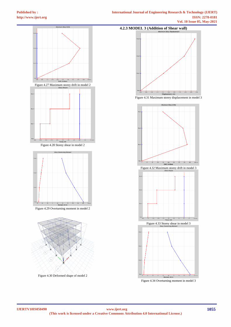
Figure 4.27 Maximum storey drift in model 2
Figure 4.28 Storey shear in model 2
Figure 4.29 Overturning moment in model 2
Figure 4.30 Deformed shape of model 2
4.2.3 MODEL 3 (Addition of Shear wall)
Figure 4.31 Maximum storey displacement in model 3
Figure 4.32 Maximum storey drift in model 3
Figure 4.33 Storey shear in model 3
Figure 4.34 Overturning moment in model 3
International Journal of Engineering Research & Technology (IJERT)
ISSN: 2278-0181http://www.ijert.org
IJERTV10IS050490(This work is licensed under a Creative Commons Attribution 4.0 International License.)
Published by :
www.ijert.org
Vol. 10 Issue 05, May-2021
1055

Figure 4.35 Deformed shape of model 3
4.2.4 MODEL 4(Steel Bracing)
Figure 4.36 Maximum storey displacement in model 4
Figure 4.37 Maximum storey drift in model 4
Figure 4.38 Storey shear in model 4
Figure 4.39 Overturning moment in model 4
Figure 4.40 Deformed shape of model 4
5. COMPARISON OF RESULTS
5.1 CASE 1 (100 Kg Blast load from 30 m Standoff
distance)
5.1.1 MAXIMUM STOREY DISPLACEMENT
Figure 5.1 Maximum storey displacements in X direction in Case 1
International Journal of Engineering Research & Technology (IJERT)
ISSN: 2278-0181http://www.ijert.org
IJERTV10IS050490(This work is licensed under a Creative Commons Attribution 4.0 International License.)
Published by :
www.ijert.org
Vol. 10 Issue 05, May-2021
1056

Figure 5.2 Maximum storey displacements in Y direction in Case 1
5.1.2 MAXIMUM STOREY DRIFT
Figure 5.3 Maximum storey drifts in Case 1 in Y Direction
5.2 CASE 2 (100 Kg Blast load from 20 m Standoff
distance)
5.2.1 MAXIMUM STOREY DISPLACEMENT
Figure 5.4 Maximum storey displacements in X direction in Case 2
Figure 5.5 Maximum storey displacements in Y direction in Case 2
5.2.2 MAXIMUM STOREY DRIFT
Figure 5.6 Maximum storey drifts in Case 2 in X Direction
Figure 5.7 Maximum storey drifts in Case 2 in Y Direction
6. CONCLUSIONS
As per the results Problem Properties obtained from the
analysis, the following conclusions can be drawn:
• The displacement and storey drifts increase drastically
with the increase of blast load and decrease of standoff
distance in the structure. Blast parameters are dependant
on blast load and standoff distance. Therefore, the response
of the structure depends majorly on blast load and standoff
distance values.
• The maximum lateral displacement are 380 mm, 150 mm
for 300 kg blast load from 30m and 20 m standoff distance,
and 73.4mm, 168.5mm are the lateral displacement for 100
kg blast load from 30 m and 20 m standoff distance for
model no 1 (Normal cross-section structure which is not
designed for blast resistance).18 mm is the allowable
maximum lateral displacement as per IS 1893 (H/500).
Thus, the maximum lateral displacement is not satisfying
the limit given by IS Code in model 1.
International Journal of Engineering Research & Technology (IJERT)
ISSN: 2278-0181http://www.ijert.org
IJERTV10IS050490(This work is licensed under a Creative Commons Attribution 4.0 International License.)
Published by :
www.ijert.org
Vol. 10 Issue 05, May-2021
1057

• The maximum Inter storey drifts are 54.3, 21.4 for 300 Kg
blast load from 30 m and 20 m standoff distance, and
10.5,24 are the max storey drift for 100kg blast load from
30 m and 20 m standoff distance for the model 1.
According to IS 1893 maximum allowable storey drift is
12 (.004* Storey height). Hence, maximum storey drift are
not satisfying IS code recommendation in model 1.
• For all the cases in model 2 when we increase beam and
column cross-section of structure compared to model one
the maximum storey displacement are reduced by around
70 %., and maximum storey drift reduced by around 65%.
• In model 3, the addition of shear wall around the structure
in model 1 results in the reduction of maximum storey
displacement by around 95 %, and max storey drift by
around 95% compared to the maximum storey
displacement and drift from model 1.In this model shear
wall helps to decrease storey displacement effectively so
that the maximum displacement and maximum storey drift
in this model are within the allowable max storey
displacement and max storey drift given by IS 1893.
• In model 4, the addition of steel bracing around the
structure helps to reduce the maximum storey
displacement by around 80% and maximum storey shear
by around 80% compared to maximum storey
displacement and maximum storey shear from model 1.
• Large values of storey shear and overturning moments are
developed due to blast loads. In order to resist these
moments and storey shear, large cross sections are
required. Here outer shear wall structure and steel braced
structure demonstrate more resistance against these.
7. FUTURE SCOPE
• A thorough study could be carried out on structures taking
into account heavier blast loads. The effects of blast loads
in high rise structures could also be studied in detail.
• The variation between reactions of symmetrical structures
as compared to non-symmetrical structures could be
studies.
• Improvement in resistance of the structure to blast loads
could be conducted as a study by using different types of
steel bracings and adding internal shear walls. The location
of shear wall addition can also be studied.
REFERENCES
[1] Baker, W. E., Cox, P. A., Westine, P. S., Kulesz, J. J., & Strehlow,
R. A. (1983). Explosion hazards and evaluation, vol. 5 of
Fundamental studies in engineering.
[2] TM-5-1300 Structures to Resist the Effects of Accidental
Explosions USA 1990 [3] Krauthammer, T., Marchand, K. A., Stevens, D. J., Bounds, W. L.,
& Nene, M. (1994). Effects of short duration dynamic loads on RC
structures. Concrete International, 16(10), 57-63. [4] Ettouney, M., Smilowitz, R., & Rittenhouse, T. (1996). Blast
resistant design of commercial buildings. Practice Periodical on
Structural Design and Construction, 1(1), 31-39. [5] Wilson, E. L. (1996). Three-dimensional static and dynamic
analysis of structures. Computers and Structures, Inc., Berkeley,
CA. [6] Crawford, J. E., Malvar, L. J., Wesevich, J. W., Valancius, J., &
Reynolds, A. D. (1997). Retrofit of reinforced concrete structures
to resist blast effects. ACI Structural Journal, 94(4).
[7] Krauthammer, T. (1999). Blast-resistant structural concrete and
steel connections. International Journal of Impact Engineering,
22(9), 887-910. [8] Gatuingt, F., & Pijaudier-Cabot, G. (2000). Computational
modelling of concrete structures subjected to explosion and
perforation. Proceeding of Eccomass. [9] Muszynski, L. C., & Purcell, M. R. (2003). Composite
reinforcement to strengthen existing concrete structures against air
blast. Journal of Composites for Construction, 7(2), 93-97. [10] IS: 4991 - 1968 (Reaffirmed 2003) Criteria for Blast Resistant
Design Of Structures for Explosions above Ground
[11] Luccioni, B. M., Ambrosini, R. D., & Danesi, R. F. (2004). Analysis of building collapse under blast loads. Engineering structures,
26(1), 63-71. [12] Marjanishvili, S. M. (2004). Progressive analysis procedure for
progressive collapse. Journal of Performance of Constructed
Facilities, 18(2), 79-85. [13] Ngo, T., Mendis, P., Gupta, A., & Ramsay, J. (2007). Blast loading
and blast effects on structures–an overview. Electroni
[14] Koccaz, Z., Sutcu, F., & Torunbalci, N. (2008). Architectural and structural design for blast resistant buildings. In The 14th World
Conference on Earthquake Engineering, Beijing, China.
[15] Hrvoje Draganić, and Vladimir Sigmund (2012) ‘Blast Loading On Structures’ Technical Gazette 19, 3). ISSN 1330-3651 UDC/UDK
624.01.04:662.15.
[16] Vasilis Karlos and George Solomos (2013) ‘Calculation of Blast Loads for Application to Structural Components’ European
Commission Joint Research Centre.
[17] Priyanka, A., & Rajeeva, S. V. (2013), Dynamic Response of a Multi-Story Building under Blast Load.
[18] Quazi Kashif1, Dr. M. B. Varma (2014) ‘ Effect of Blast on G+4
RCC Frame Structure’, ISSN 2250-2459 [19] Singla, S., Singla, P., & Singla, (2015) A. Computation Of Blast
Loading For A Multi Storeyed Framed Building.
International Journal of Engineering Research & Technology (IJERT)
ISSN: 2278-0181http://www.ijert.org
IJERTV10IS050490(This work is licensed under a Creative Commons Attribution 4.0 International License.)
Published by :
www.ijert.org
Vol. 10 Issue 05, May-2021
1058