Embed Size (px)
Citation preview

Kawasaki Heavy Industries, Ltd.
90202-1111DEG
Installation and Connection Manual
E Series (Explosion-proof type)
E Series Controller (Explosion-proof spec.) Kawasaki Robot Installation and Connection Manual
1
PREFACE This manual describes the installation and connection of the E series controllers. (Explosion-proof spec.) This manual covers the installation, wiring and connection with external controller, devices and power. Please refer to “Operation Manual” and “External I/O Manual” for the operation of the controller. Read and understand the contents of this and safety manuals thoroughly and strictly observe all rules for safety before proceeding with any operation. This manual describes only the installation and connection of the controller. For the robot arms, please refer to the separate manuals for them. This manual also describes devices equipped as an option; however, all the controllers might not include the devices explained here.
1. This manual does not constitute a guarantee of the systems in which the robot is utilized.
Accordingly, Kawasaki is not responsible for any accidents, damages, and/or problems relating to industrial property rights as a result of using the system.
2. It is recommended that all personnel assigned for activation of operation, teaching, maintenance or inspection of the robot attend the necessary education/training course(s) prepared by Kawasaki, before assuming their responsibilities.
3. Kawasaki reserves the right to change, revise, or update this manual without prior notice. 4. This manual may not, in whole or in part, be reprinted or copied without the prior written
consent of Kawasaki. 5. Store this manual with care and keep it available for use at any time. If the robot is
reinstalled or moved to a different site or sold off to a different user, attach this manual to the robot without fail. In the event the manual is lost or damaged severely, contact Kawasaki.
Copyright © 2015 Kawasaki Heavy Industries Ltd. All rights reserved.
This manual is applicable to the following controller models.
E25, E27 (Japan/China/Korea spec.) E35, E37 (North America spec.) E45, E47 (Europe spec.)

E Series Controller (Explosion-proof spec.) Kawasaki Robot Installation and Connection Manual
2
SYMBOLS The items that require special attention in this manual are designated with the following symbols. Ensure proper and safe operation of the robot and prevent physical injury or property damage by complying with the safety matters given in the boxes with these symbols.
Failure to comply with indicated matters may possibly lead to injury or death.
! WARNING
[ NOTE ]
Denotes precautions regarding robot specification, handling, teaching, operation and maintenance.
DANGER !
Failure to comply with indicated matters can result in imminent injury or death.
1. The accuracy and effectiveness of the diagrams, procedures, and detail explanations given in this manual cannot be confirmed with absolute certainty. Should any unexplained questions or problems arise, contact Kawasaki.
2. Safety related contents described in this manual apply to each individual work and not to all robot work. In order to perform every work in safety, read and fully understand the safety manual, all pertinent laws, regulations and related materials as well as all the safety explanation described in each chapter, and prepare safety measures suitable for actual work.
! WARNING
!
Failure to comply with indicated matters may lead to physical injury and/or mechanical damage.
CAUTION
E Series Controller (Explosion-proof spec.) Kawasaki Robot Installation and Connection Manual
3
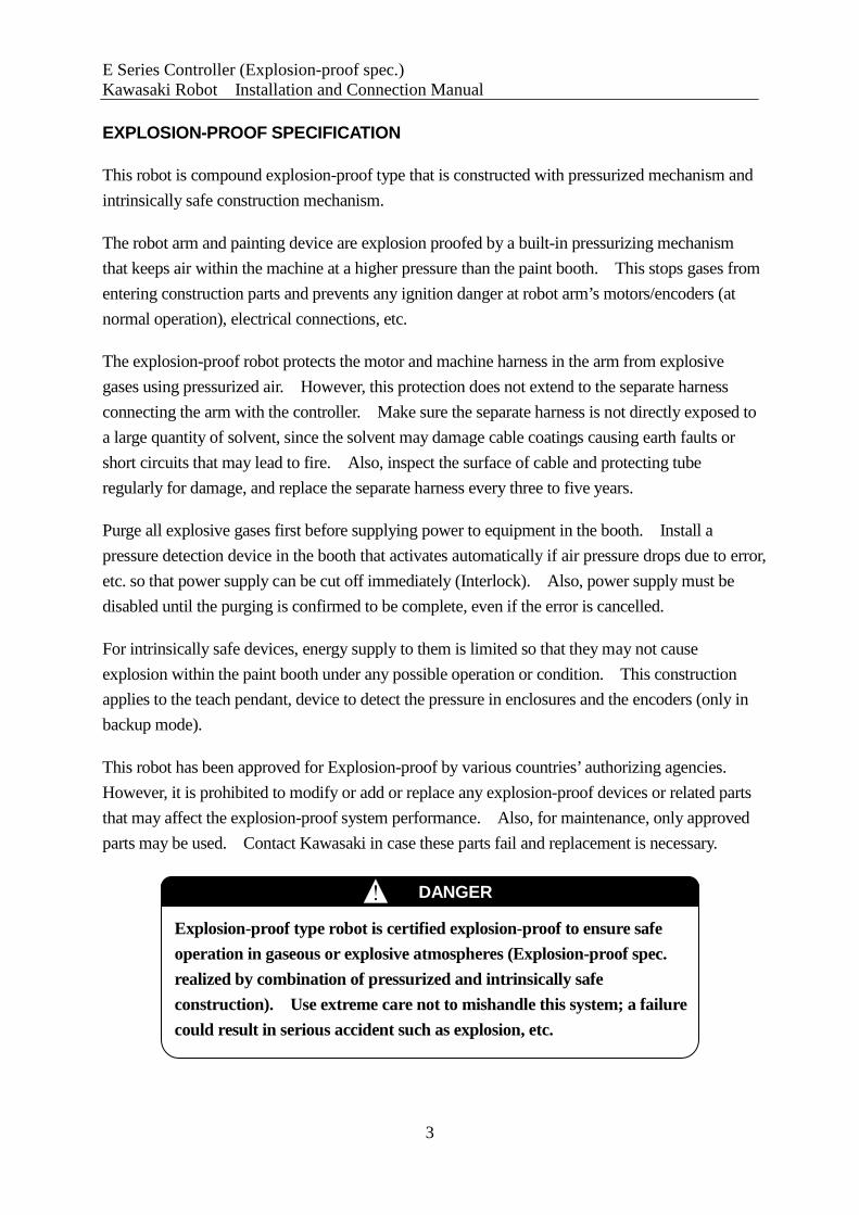
EXPLOSION-PROOF SPECIFICATION This robot is compound explosion-proof type that is constructed with pressurized mechanism and intrinsically safe construction mechanism. The robot arm and painting device are explosion proofed by a built-in pressurizing mechanism that keeps air within the machine at a higher pressure than the paint booth. This stops gases from entering construction parts and prevents any ignition danger at robot arm’s motors/encoders (at normal operation), electrical connections, etc. The explosion-proof robot protects the motor and machine harness in the arm from explosive gases using pressurized air. However, this protection does not extend to the separate harness connecting the arm with the controller. Make sure the separate harness is not directly exposed to a large quantity of solvent, since the solvent may damage cable coatings causing earth faults or short circuits that may lead to fire. Also, inspect the surface of cable and protecting tube regularly for damage, and replace the separate harness every three to five years. Purge all explosive gases first before supplying power to equipment in the booth. Install a pressure detection device in the booth that activates automatically if air pressure drops due to error, etc. so that power supply can be cut off immediately (Interlock). Also, power supply must be disabled until the purging is confirmed to be complete, even if the error is cancelled. For intrinsically safe devices, energy supply to them is limited so that they may not cause explosion within the paint booth under any possible operation or condition. This construction applies to the teach pendant, device to detect the pressure in enclosures and the encoders (only in backup mode). This robot has been approved for Explosion-proof by various countries’ authorizing agencies. However, it is prohibited to modify or add or replace any explosion-proof devices or related parts that may affect the explosion-proof system performance. Also, for maintenance, only approved parts may be used. Contact Kawasaki in case these parts fail and replacement is necessary. DANGER !
Explosion-proof type robot is certified explosion-proof to ensure safe operation in gaseous or explosive atmospheres (Explosion-proof spec. realized by combination of pressurized and intrinsically safe construction). Use extreme care not to mishandle this system; a failure could result in serious accident such as explosion, etc.

E Series Controller (Explosion-proof spec.) Kawasaki Robot Installation and Connection Manual
4
Preface ··········································································································· 1 Symbols ········································································································· 2 Explosion-Proof Specification ················································································ 3 1.0 Safety ······································································································ 6 1.1 Precautions during Transportation, Installation and Storage ······································ 6 1.2 Installation Environments of Robot Controller ······················································ 7 1.3 When Connecting the Harnesses ······································································ 9 1.4 When Connecting the External Power ······························································ 10 1.5 Warning Label for Electric Shock ·································································· 12 1.6 Battery and Fuse Use and Disposal ································································· 13 1.7 Safety Features ························································································· 14 1.8 Emergency Movement without Drive Power ······················································ 15 2.0 Workflow - Robot Controller Installation and Connection ······································ 18 3.0 Appearance and Specification of Robot Controller ··············································· 20 3.1 Controller Appearance ················································································ 20 3.2 Teach Pendant Appearance ·········································································· 26 3.3 E2x Controller Specification ········································································· 27 3.4 E3x Controller Specification ········································································· 28 3.5 E4x Controller Specification ········································································· 29 4.0 Transportation of Robot Controller ································································· 30 4.1 By Crane Lifting ······················································································· 30 4.2 By Caster ······························································································· 31 5.0 Arrangement of Robot Controller ··································································· 32 6.0 Connection Instructions ·············································································· 34 6.1 Connection between Controller and Robot ························································ 34 6.2 Connection between Controller and Teach Pendant ·············································· 37 6.3 Connection of Dedicated Earth Wire between Controller and Arm ···························· 38 7.0 Connection of External Power ······································································· 48
CONTENTS
E Series Controller (Explosion-proof spec.) Kawasaki Robot Installation and Connection Manual
5
8.0 Connection of Peripheral Control Equipment ····················································· 53 8.1 Instructions at the Connection ······································································· 54 8.2 Connection of General Purpose Signal ····························································· 55 8.3 Connection of Hardware Dedicated Signal ························································ 56 8.4 Connection of Personal Computer ·································································· 57 8.5 Connection of RS-232C Serial Signal (Option) ··················································· 57 8.6 Connection of Ethernet Communication Signal (Option) ······································· 57 8.7 Connection of Fieldbus (Option) ···································································· 57
E Series Controller (Explosion-proof spec.) 1. Safety Kawasaki Robot Installation and Connection Manual
6
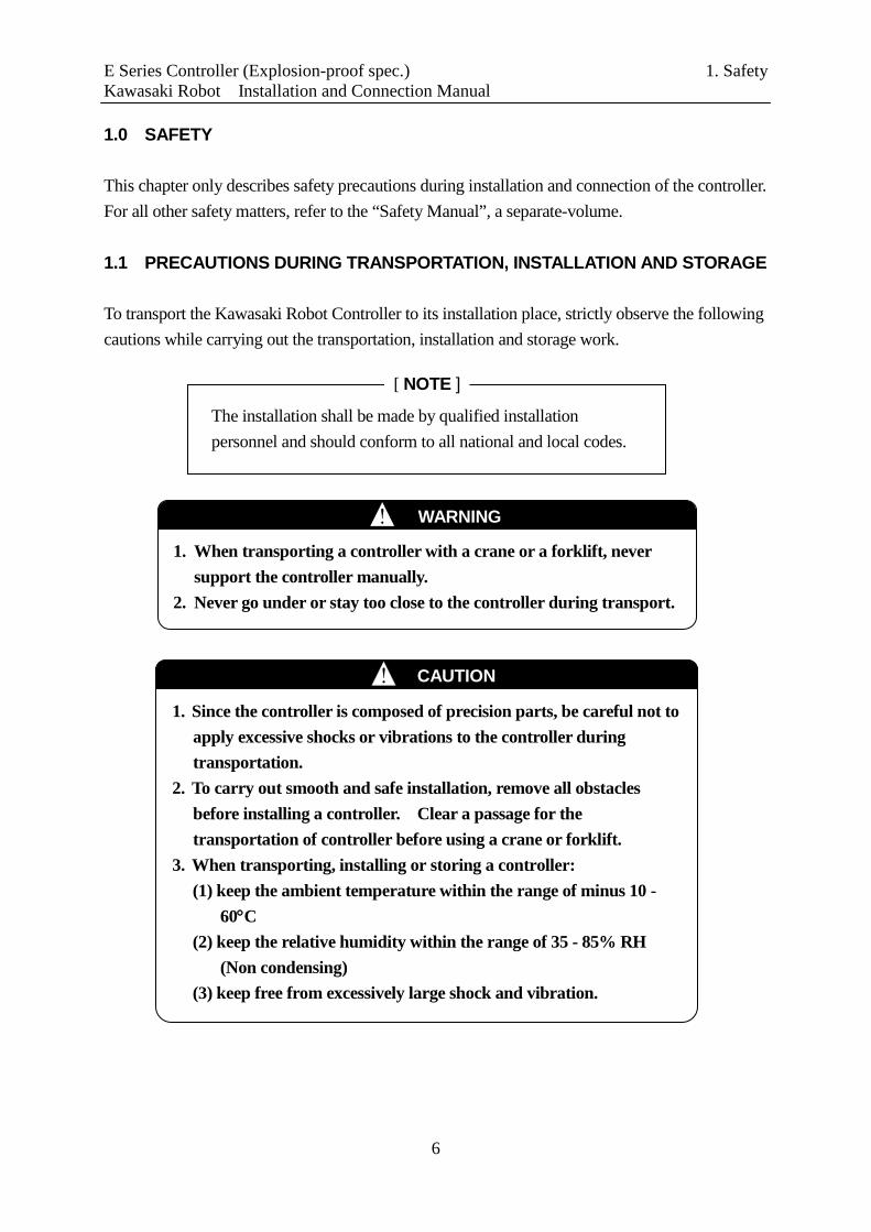
1.0 SAFETY This chapter only describes safety precautions during installation and connection of the controller. For all other safety matters, refer to the “Safety Manual”, a separate-volume. 1.1 PRECAUTIONS DURING TRANSPORTATION, INSTALLATION AND STORAGE To transport the Kawasaki Robot Controller to its installation place, strictly observe the following cautions while carrying out the transportation, installation and storage work.
1. When transporting a controller with a crane or a forklift, never support the controller manually.
2. Never go under or stay too close to the controller during transport.
! WARNING
[ NOTE ]
The installation shall be made by qualified installation personnel and should conform to all national and local codes.
1. Since the controller is composed of precision parts, be careful not to apply excessive shocks or vibrations to the controller during transportation.
2. To carry out smooth and safe installation, remove all obstacles before installing a controller. Clear a passage for the transportation of controller before using a crane or forklift.
3. When transporting, installing or storing a controller: (1) keep the ambient temperature within the range of minus 10 -
60°C (2) keep the relative humidity within the range of 35 - 85% RH
(Non condensing) (3) keep free from excessively large shock and vibration.
! CAUTION
E Series Controller (Explosion-proof spec.) 1. Safety Kawasaki Robot Installation and Connection Manual
7
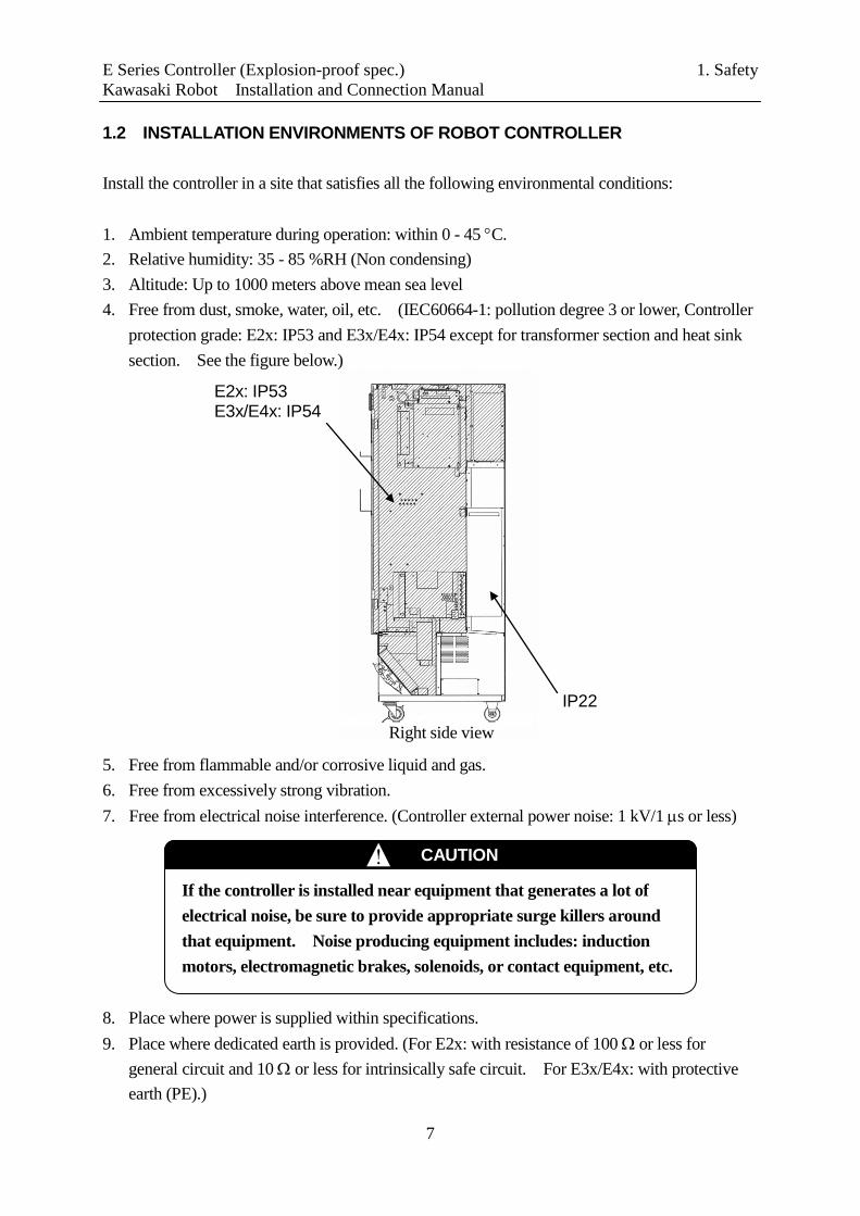
1.2 INSTALLATION ENVIRONMENTS OF ROBOT CONTROLLER Install the controller in a site that satisfies all the following environmental conditions: 1. Ambient temperature during operation: within 0 - 45 °C. 2. Relative humidity: 35 - 85 %RH (Non condensing) 3. Altitude: Up to 1000 meters above mean sea level 4. Free from dust, smoke, water, oil, etc. (IEC60664-1: pollution degree 3 or lower, Controller
protection grade: E2x: IP53 and E3x/E4x: IP54 except for transformer section and heat sink section. See the figure below.)
5. Free from flammable and/or corrosive liquid and gas. 6. Free from excessively strong vibration. 7. Free from electrical noise interference. (Controller external power noise: 1 kV/1 µs or less) 8. Place where power is supplied within specifications. 9. Place where dedicated earth is provided. (For E2x: with resistance of 100 Ω or less for
general circuit and 10 Ω or less for intrinsically safe circuit. For E3x/E4x: with protective earth (PE).)
E2x: IP53 E3x/E4x: IP54
IP22
Right side view
If the controller is installed near equipment that generates a lot of electrical noise, be sure to provide appropriate surge killers around that equipment. Noise producing equipment includes: induction motors, electromagnetic brakes, solenoids, or contact equipment, etc.
! CAUTION
E Series Controller (Explosion-proof spec.) 1. Safety Kawasaki Robot Installation and Connection Manual
8
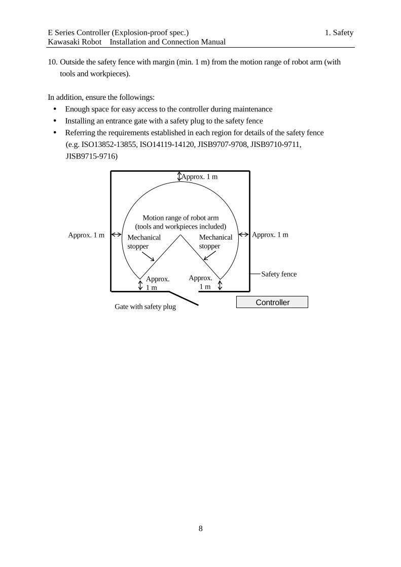
10. Outside the safety fence with margin (min. 1 m) from the motion range of robot arm (with tools and workpieces).
In addition, ensure the followings: Enough space for easy access to the controller during maintenance Installing an entrance gate with a safety plug to the safety fence Referring the requirements established in each region for details of the safety fence
(e.g. ISO13852-13855, ISO14119-14120, JISB9707-9708, JISB9710-9711, JISB9715-9716)
Approx. 1 m
Safety fence
Motion range of robot arm (tools and workpieces included)
Gate with safety plug Controller
Mechanical stopper
Mechanical stopper
Approx. 1 m
Approx. 1 m
Approx. 1 m
Approx. 1 m
E Series Controller (Explosion-proof spec.) 1. Safety Kawasaki Robot Installation and Connection Manual
9
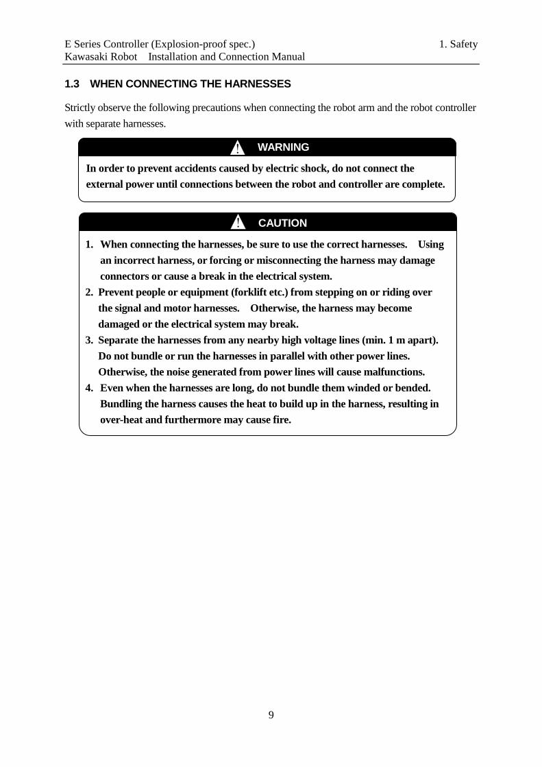
1.3 WHEN CONNECTING THE HARNESSES
Strictly observe the following precautions when connecting the robot arm and the robot controller with separate harnesses.
In order to prevent accidents caused by electric shock, do not connect the external power until connections between the robot and controller are complete.
! WARNING
1. When connecting the harnesses, be sure to use the correct harnesses. Using an incorrect harness, or forcing or misconnecting the harness may damage connectors or cause a break in the electrical system.
2. Prevent people or equipment (forklift etc.) from stepping on or riding over the signal and motor harnesses. Otherwise, the harness may become damaged or the electrical system may break.
3. Separate the harnesses from any nearby high voltage lines (min. 1 m apart). Do not bundle or run the harnesses in parallel with other power lines. Otherwise, the noise generated from power lines will cause malfunctions.
4. Even when the harnesses are long, do not bundle them winded or bended. Bundling the harness causes the heat to build up in the harness, resulting in over-heat and furthermore may cause fire.
! CAUTION

E Series Controller (Explosion-proof spec.) 1. Safety Kawasaki Robot Installation and Connection Manual
10
1.4 WHEN CONNECTING THE EXTERNAL POWER
Strictly observe the following precautions when connecting the external power.
1. Make sure the power supply to be connected to the controller meets the specifications listed on the rating plate and label on the side of the breaker. Connecting to a power source outside specifications may damage internal components.
2. Earth the controller to prevent against electrical noise and shock. (For E2x) 2 kinds of dedicated ground lines are required; one with ground resistance 10 Ω or less, important to secure intrinsically safe explosion-proof operation, and another with resistance of 100 Ω or less for general circuit. Be sure to connect each ground line to each specified place without fail. Use earth wire of correct size as shown in 3.3. (For E3x/E4x) Protective earth is required. This is important to secure intrinsically safe explosion-proof operation so connect without fail to the specified place. Use earth wire of correct size as shown in 3.4 and 3.5.
3. Do not use a common earth wire for the controller and the other devices. Also, do not connect earth wires of several controllers to one earth port.
4. Without fail, before turning ON the external power to controller, make sure the power supply wiring is complete and all the covers reattached properly. Failure to do so may cause electric shock.
5. Orange electric cables in the controller are possibly alive even when external power is turned OFF, so be careful.
! WARNING
Confirm that external power supply for the controller is cut off at the source before starting connection process. Failing to do so is extremely dangerous, resulting in accidents, electric shock, etc. To prevent external power from being turned ON, tag the breaker to indicate clearly that work is in progress. Or, assign a supervisor in front of the breaker until all the connections are complete.
DANGER !
E Series Controller (Explosion-proof spec.) 1. Safety Kawasaki Robot Installation and Connection Manual
11
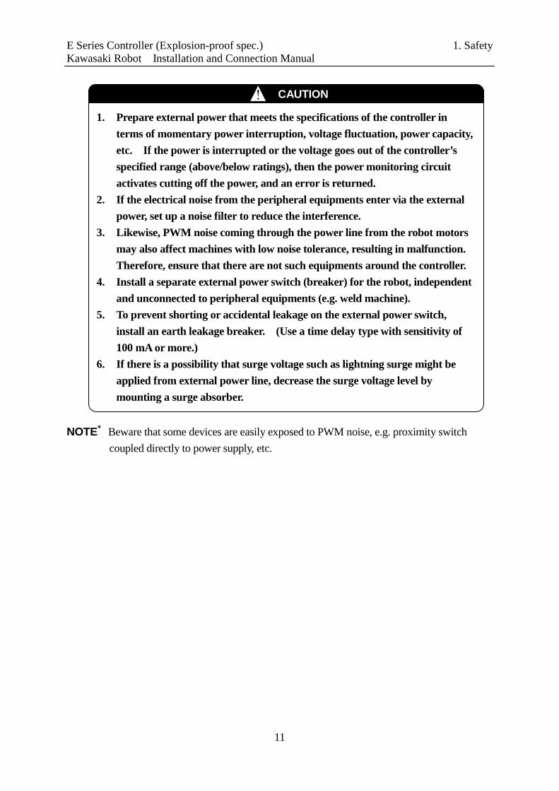
NOTE* Beware that some devices are easily exposed to PWM noise, e.g. proximity switch
coupled directly to power supply, etc.
1. Prepare external power that meets the specifications of the controller in terms of momentary power interruption, voltage fluctuation, power capacity, etc. If the power is interrupted or the voltage goes out of the controller’s specified range (above/below ratings), then the power monitoring circuit activates cutting off the power, and an error is returned.
2. If the electrical noise from the peripheral equipments enter via the external power, set up a noise filter to reduce the interference.
3. Likewise, PWM noise coming through the power line from the robot motors may also affect machines with low noise tolerance, resulting in malfunction. Therefore, ensure that there are not such equipments around the controller.
4. Install a separate external power switch (breaker) for the robot, independent and unconnected to peripheral equipments (e.g. weld machine).
5. To prevent shorting or accidental leakage on the external power switch, install an earth leakage breaker. (Use a time delay type with sensitivity of 100 mA or more.)
6. If there is a possibility that surge voltage such as lightning surge might be applied from external power line, decrease the surge voltage level by mounting a surge absorber.
! CAUTION

E Series Controller (Explosion-proof spec.) 1. Safety Kawasaki Robot Installation and Connection Manual
12
1.5 WARNING LABEL FOR ELECTRIC SHOCK Warning labels for electric shock are on the location below.
Controller power switch
The terminals are still alive even though the Controller power switch is OFF.
DC power supply (AVR)
Servo amplifier
Front (Door omitted)
MC unit
Transformer cover (E3x/E4x)
Transformer cover (E3x controller only)

E Series Controller (Explosion-proof spec.) 1. Safety Kawasaki Robot Installation and Connection Manual
13
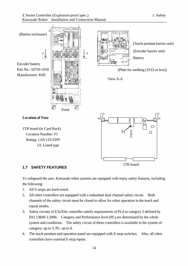
1.6 BATTERY AND FUSE USE AND DISPOSAL Batteries are used for data backup in the controller. Figures below and on the next page show the location of the batteries on the 1TA/1VA board and for encoder backup. If not used and disposed of properly these batteries may malfunction, ignite, overheat, explode, corrode, leak, etc. Always use and dispose of all batteries in compliance with the following warnings and cautions. Figure on the next page shows the location of fuse F1 (1.0 A, 125 V/250 V) on the 1TR board. Locations of Batteries 1TA/1VA board (in Card Rack) Location Number: E1
Model: BR2032 Manufacturer: Panasonic
E1
1. Only use batteries specified by Kawasaki. 2. Never re-charge, dismantle, convert and/or overheat batteries. 3. Never dispose of batteries into water or fire. 4. Batteries with damaged cases may short internally and must not be used. 5. Never short the positive and negative poles of a battery with material
such as wire.
! WARNING
Never dispose of depleted batteries with garbage that is disposed of in an incinerator, land-fill, dumping-ground, etc. When disposing of batteries, insulate with tape so as not to contact other metal. Comply with local regulations and rules for battery disposal.
! CAUTION
E Series Controller (Explosion-proof spec.) 1. Safety Kawasaki Robot Installation and Connection Manual
14
Location of Fuse
1TR board (in Card Rack) Location Number: F1 Rating: 1.0A 125/250V UL Listed type 1.7 SAFETY FEATURES To safeguard the user, Kawasaki robot systems are equipped with many safety features, including the following: 1. All E-stops are hard-wired. 2. All robot controllers are equipped with a redundant dual channel safety circuit. Both
channels of the safety circuit must be closed to allow for robot operation in the teach and repeat modes.
3. Safety circuits of E3x/E4x controller satisfy requirements of PLd in category 3 defined by ISO 13849-1:2006. Category and Performance level (PL) are determined by the whole system and conditions. The safety circuit of these controllers is available in the system of category: up to 3, PL: up to d.
4. The teach pendant and operation panel are equipped with E-stop switches. Also, all robot controllers have external E-stop inputs.
1TR board
F1
A
Front
(Barrier enclosure)
Encoder battery Part No.: 50750-1018 Manufacturer: KHI
A
View A-A
(Plate for earthing (10 Ω or less))
(Teach pendant barrier unit)
(Encoder barrier unit)
Battery
E Series Controller (Explosion-proof spec.) 1. Safety Kawasaki Robot Installation and Connection Manual
15
5. The teach pendant is equipped with two, three-position, enabling devices. One of the two enabling devices must be pressed to enable motor power in the teach and check modes.
6. Teach and check mode velocities are limited to a maximum of 250 mm/s (10.0 in/s). E4x controller is equipped with Fast Check mode that satisfies requirements of ISO 10218-1:2006. The velocities are not limited to 250 mm/s (10.0 in/s) in the Fast Check Mode.
7. All robot axes are equipped with 24 VDC electromagnetic brakes that engage when power is removed. If the robot loses power unexpectedly, the axes are held in position by the brakes.
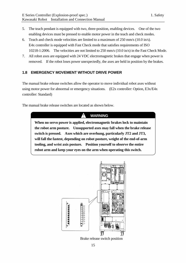
1.8 EMERGENCY MOVEMENT WITHOUT DRIVE POWER The manual brake release switches allow the operator to move individual robot axes without using motor power for abnormal or emergency situations. (E2x controller: Option, E3x/E4x controller: Standard) The manual brake release switches are located as shown below.
Brake release switch position
When no servo power is applied, electromagnetic brakes lock to maintain the robot arm posture. Unsupported axes may fall when the brake release switch is pressed. Axes which are overhung, particularly JT2 and JT3, will fall the fastest, depending on robot posture, weight of the end-of-arm tooling, and wrist axis posture. Position yourself to observe the entire robot arm and keep your eyes on the arm when operating this switch.
! WARNING
E Series Controller (Explosion-proof spec.) 1. Safety Kawasaki Robot Installation and Connection Manual
16
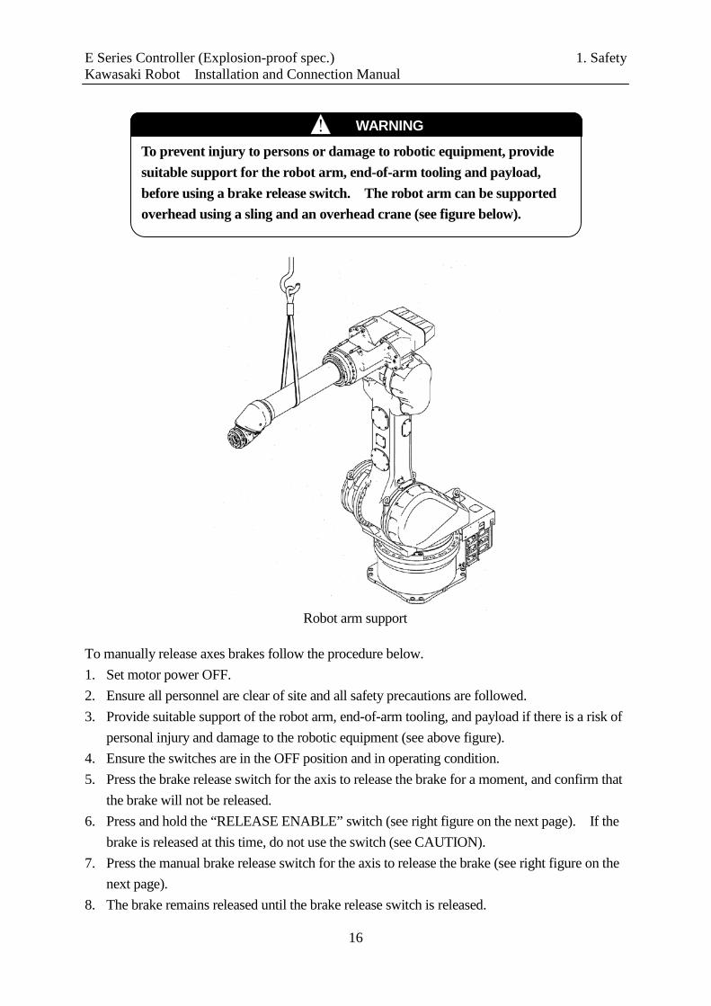
To manually release axes brakes follow the procedure below. 1. Set motor power OFF. 2. Ensure all personnel are clear of site and all safety precautions are followed. 3. Provide suitable support of the robot arm, end-of-arm tooling, and payload if there is a risk of
personal injury and damage to the robotic equipment (see above figure). 4. Ensure the switches are in the OFF position and in operating condition. 5. Press the brake release switch for the axis to release the brake for a moment, and confirm that
the brake will not be released. 6. Press and hold the “RELEASE ENABLE” switch (see right figure on the next page). If the
brake is released at this time, do not use the switch (see CAUTION). 7. Press the manual brake release switch for the axis to release the brake (see right figure on the
next page). 8. The brake remains released until the brake release switch is released.
Robot arm support
To prevent injury to persons or damage to robotic equipment, provide suitable support for the robot arm, end-of-arm tooling and payload, before using a brake release switch. The robot arm can be supported overhead using a sling and an overhead crane (see figure below).
! WARNING

E Series Controller (Explosion-proof spec.) 1. Safety Kawasaki Robot Installation and Connection Manual
17
Robot brake release axes Manual brake release SW
RELEASE ENABLE Switch
CAUTION !
Stop using the manual brake release switch immediately if the electromagnetic brake is released by pressing only one switch. The switch may be defective.
E Series Controller (Explosion-proof spec.) 2. Workflow - Robot Controller Kawasaki Robot Installation and Connection Manual Installation and Connection
18
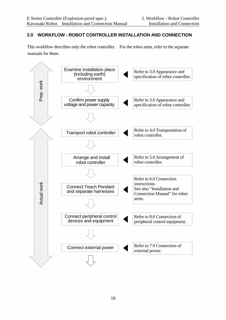
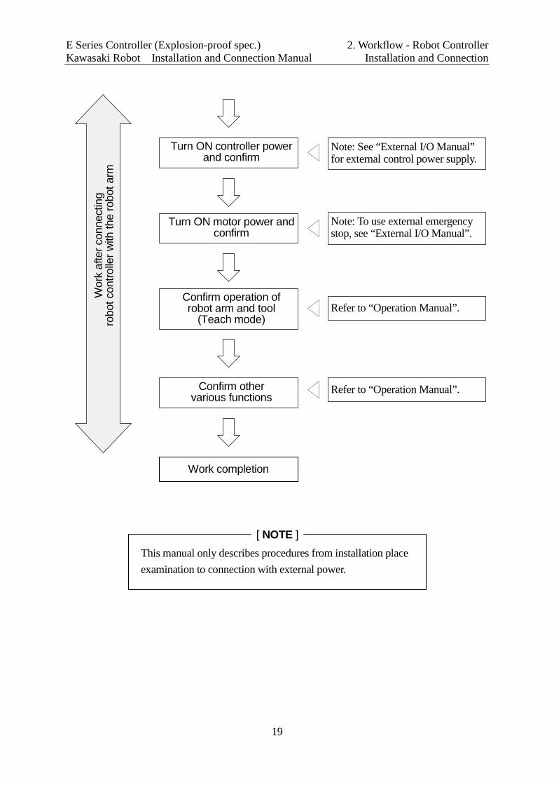
2.0 WORKFLOW - ROBOT CONTROLLER INSTALLATION AND CONNECTION This workflow describes only the robot controller. For the robot arms, refer to the separate manuals for them.
Prep
. wor
k Ac
tual
wor
k
Examine installation place (including earth)
environment
Confirm power supply voltage and power capacity
Transport robot controller
Arrange and install robot controller
Connect Teach Pendant and separate harnesses
Connect external power
Refer to 3.0 Appearance and specification of robot controller.
Refer to 3.0 Appearance and specification of robot controller.
Refer to 4.0 Transportation of robot controller.
Refer to 5.0 Arrangement of robot controller.
Refer to 7.0 Connection of external power.
Refer to 6.0 Connection instructions. See also “Installation and Connection Manual” for robot arms.
Connect peripheral control devices and equipment
Refer to 8.0 Connection of peripheral control equipment.
E Series Controller (Explosion-proof spec.) 2. Workflow - Robot Controller Kawasaki Robot Installation and Connection Manual Installation and Connection
19
Wor
k af
ter c
onne
ctin
g ro
bot c
ontro
ller w
ith th
e ro
bot a
rm
Turn ON controller power and confirm
Turn ON motor power and confirm
Confirm operation of robot arm and tool
(Teach mode)
Confirm other various functions
Note: See “External I/O Manual” for external control power supply.
Note: To use external emergency stop, see “External I/O Manual”.
Refer to “Operation Manual”.
Refer to “Operation Manual”.
Work completion
[ NOTE ] This manual only describes procedures from installation place examination to connection with external power.

E Series Controller (Explosion-proof spec.) 3. Appearance and Specification Kawasaki Robot Installation and Connection Manual of Robot Controller
20
3.0 APPEARANCE AND SPECIFICATION OF ROBOT CONTROLLER 3.1 CONTROLLER APPEARANCE (Front view: without connector cover)
E25 controller
Front Left
Operation panel
Teach Pendant
Hook
TP connector
Accessory panel
Coin lock
Controller power switch
Lifting eyebolt
External power intake port
Rear Right
Connectors for separate harnesses (See section 6.1 for details.)
USB port
RS-232C port
Connecting ports in the accessory panel
1400
500 550
E Series Controller (Explosion-proof spec.) 3. Appearance and Specification Kawasaki Robot Installation and Connection Manual of Robot Controller
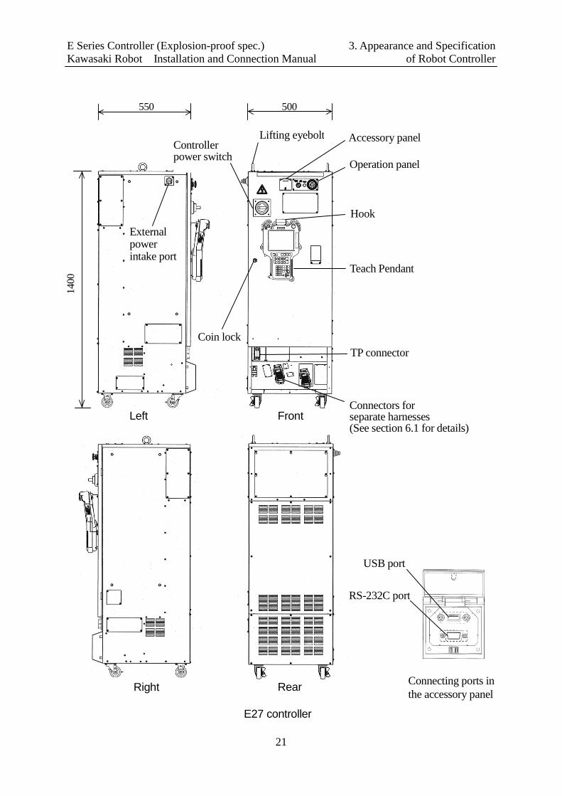
21
1400
500 550
Operation panel
Teach Pendant
Hook
TP connector
Accessory panel
Coin lock
Controller power switch
Lifting eyebolt
External power intake port
Front Left
Rear Right
E27 controller
Connectors for separate harnesses (See section 6.1 for details)
USB port
RS-232C port
Connecting ports in the accessory panel
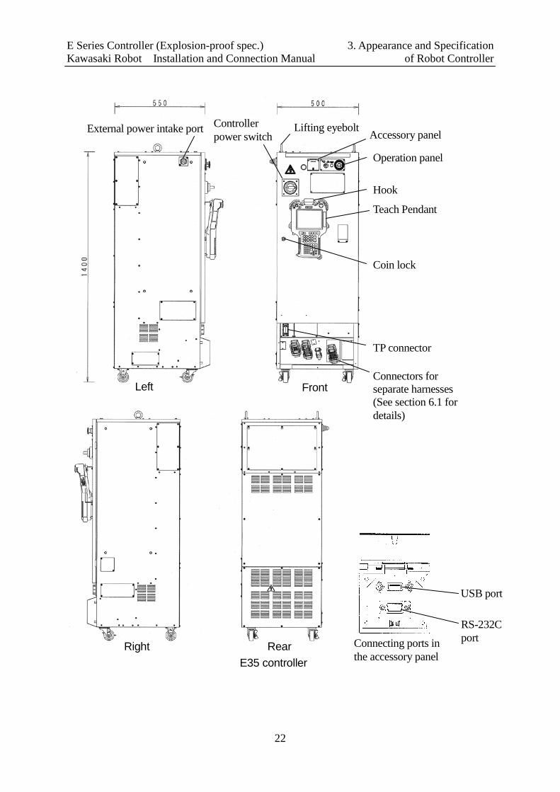
E Series Controller (Explosion-proof spec.) 3. Appearance and Specification Kawasaki Robot Installation and Connection Manual of Robot Controller
22
Connecting ports in the accessory panel
RS-232C port
USB port
Rear Right E35 controller
Operation panel
Teach Pendant
TP connector
Accessory panel
Coin lock
Lifting eyebolt
External power intake port
Front Left
Controller power switch
Hook
Connectors for separate harnesses (See section 6.1 for details)

E Series Controller (Explosion-proof spec.) 3. Appearance and Specification Kawasaki Robot Installation and Connection Manual of Robot Controller
23
E37 controller
Rear Right
Operation panel
Teach Pendant
TP connector
Accessory panel
Coin lock
Lifting eyebolt
External power intake port
Front
Left
Controller power switch
Hook
Connectors for separate harnesses (See section 6.1 for details)
Connecting ports in the accessory panel
RS-232C port
USB port

E Series Controller (Explosion-proof spec.) 3. Appearance and Specification Kawasaki Robot Installation and Connection Manual of Robot Controller
24
Operation panel
Teach Pendant
TP connector
Accessory panel
Coin lock
Lifting eyebolt External power intake port
Controller power switch
Hook
Connectors for separate harnesses (See section 6.1 for details)
Front Left
E45 controller
Rear Right Connecting ports in the accessory panel
RS-232C port
USB port

E Series Controller (Explosion-proof spec.) 3. Appearance and Specification Kawasaki Robot Installation and Connection Manual of Robot Controller
25
E47 controller
Operation panel
Teach Pendant
TP connector
Accessory panel
Coin lock
Lifting eyebolt
External power intake port Controller power switch
Hook
Connectors for separate harnesses (See section 6.1 for details)
Rear Right
Front Left
Connecting ports in the accessory panel
RS-232C port
USB port

E Series Controller (Explosion-proof spec.) 3. Appearance and Specification Kawasaki Robot Installation and Connection Manual of Robot Controller
26
3.2 TEACH PENDANT APPEARANCE
Emergency stop switch
Liquid crystal display
Teach lock switch
E Series Controller (Explosion-proof spec.) 3. Appearance and Specification Kawasaki Robot Installation and Connection Manual of Robot Controller
27
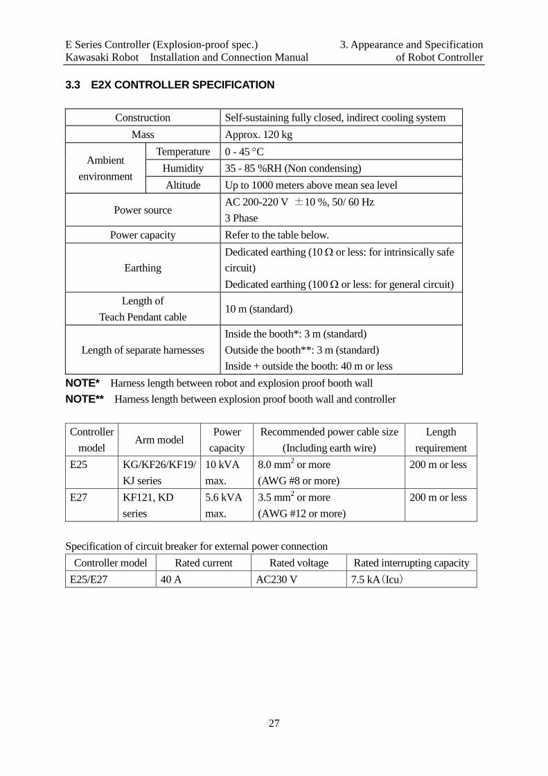
3.3 E2X CONTROLLER SPECIFICATION
Construction Self-sustaining fully closed, indirect cooling system Mass Approx. 120 kg
Ambient environment
Temperature 0 - 45 °C Humidity 35 - 85 %RH (Non condensing) Altitude Up to 1000 meters above mean sea level
Power source AC 200-220 V ±10 %, 50/ 60 Hz 3 Phase
Power capacity Refer to the table below.
Earthing Dedicated earthing (10 Ω or less: for intrinsically safe circuit) Dedicated earthing (100 Ω or less: for general circuit)
Length of Teach Pendant cable
10 m (standard)
Length of separate harnesses Inside the booth*: 3 m (standard) Outside the booth**: 3 m (standard) Inside + outside the booth: 40 m or less
NOTE* Harness length between robot and explosion proof booth wall NOTE** Harness length between explosion proof booth wall and controller Controller
model Arm model
Power capacity
Recommended power cable size (Including earth wire)
Length requirement
E25 KG/KF26/KF19/ KJ series
10 kVA max.
8.0 mm2 or more (AWG #8 or more)
200 m or less
E27 KF121, KD series
5.6 kVA max.
3.5 mm2 or more (AWG #12 or more)
200 m or less
Specification of circuit breaker for external power connection
Controller model Rated current Rated voltage Rated interrupting capacity E25/E27 40 A AC230 V 7.5 kA(Icu)
E Series Controller (Explosion-proof spec.) 3. Appearance and Specification Kawasaki Robot Installation and Connection Manual of Robot Controller
28
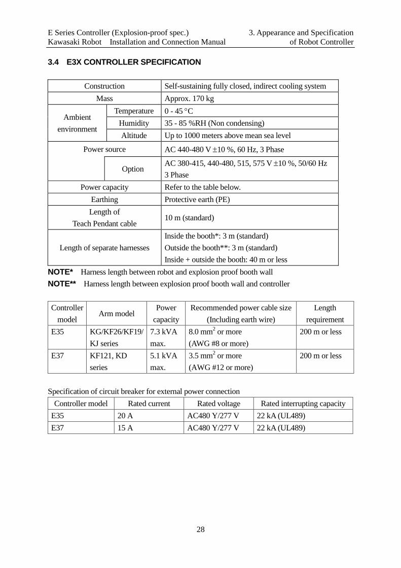
3.4 E3X CONTROLLER SPECIFICATION
Construction Self-sustaining fully closed, indirect cooling system Mass Approx. 170 kg
Ambient environment
Temperature 0 - 45 °C Humidity 35 - 85 %RH (Non condensing) Altitude Up to 1000 meters above mean sea level
Power source AC 440-480 V ±10 %, 60 Hz, 3 Phase
Option AC 380-415, 440-480, 515, 575 V ±10 %, 50/60 Hz 3 Phase
Power capacity Refer to the table below. Earthing Protective earth (PE) Length of
Teach Pendant cable 10 m (standard)
Length of separate harnesses Inside the booth*: 3 m (standard) Outside the booth**: 3 m (standard) Inside + outside the booth: 40 m or less
NOTE* Harness length between robot and explosion proof booth wall NOTE** Harness length between explosion proof booth wall and controller Controller
model Arm model
Power capacity
Recommended power cable size (Including earth wire)
Length requirement
E35 KG/KF26/KF19/ KJ series
7.3 kVA max.
8.0 mm2 or more (AWG #8 or more)
200 m or less
E37 KF121, KD series
5.1 kVA max.
3.5 mm2 or more (AWG #12 or more)
200 m or less
Specification of circuit breaker for external power connection
Controller model Rated current Rated voltage Rated interrupting capacity E35 20 A AC480 Y/277 V 22 kA (UL489) E37 15 A AC480 Y/277 V 22 kA (UL489)

E Series Controller (Explosion-proof spec.) 3. Appearance and Specification Kawasaki Robot Installation and Connection Manual of Robot Controller
29
3.5 E4X CONTROLLER SPECIFICATION
Construction Self-sustaining fully closed, indirect cooling system Mass Approx. 170 kg
Ambient environment
Temperature 0 - 45 °C Humidity 35 - 85 %RH (Non condensing) Altitude Up to 1000 meters above mean sea level
Power source AC 380-415 V ±10 %, 50/60 Hz, 3 Phase
Power capacity Refer to the table below. Earthing Protective earth (PE) Length of
Teach Pendant cable 10 m (standard)
Length of separate harnesses Inside the booth*: 3 m (standard) Outside the booth**: 3 m (standard) Inside + outside the booth: 40 m or less
NOTE* Harness length between robot and explosion proof booth wall NOTE** Harness length between explosion proof booth wall and controller Controller
model Arm model
Power capacity
Recommended power cable size (Including earth wire)
Length requirement
E45 KG/KF26/KF19/ KJ series
7.3 kVA max.
8.0 mm2 or more (AWG #8 or more)
200 m or less
E47 KF121, KD series
5.1 kVA max.
3.5 mm2 or more (AWG #12 or more)
200 m or less
Specification of circuit breaker for external power connection
Controller model Rated current Rated voltage Rated interrupting capacity E45/E47 20 A AC400 V 5 kA (Icu)
AC415 V 2.5 kA (Icu)
E Series Controller (Explosion-proof spec.) 4. Transportation of Robot Controller Kawasaki Robot Installation and Connection Manual
30
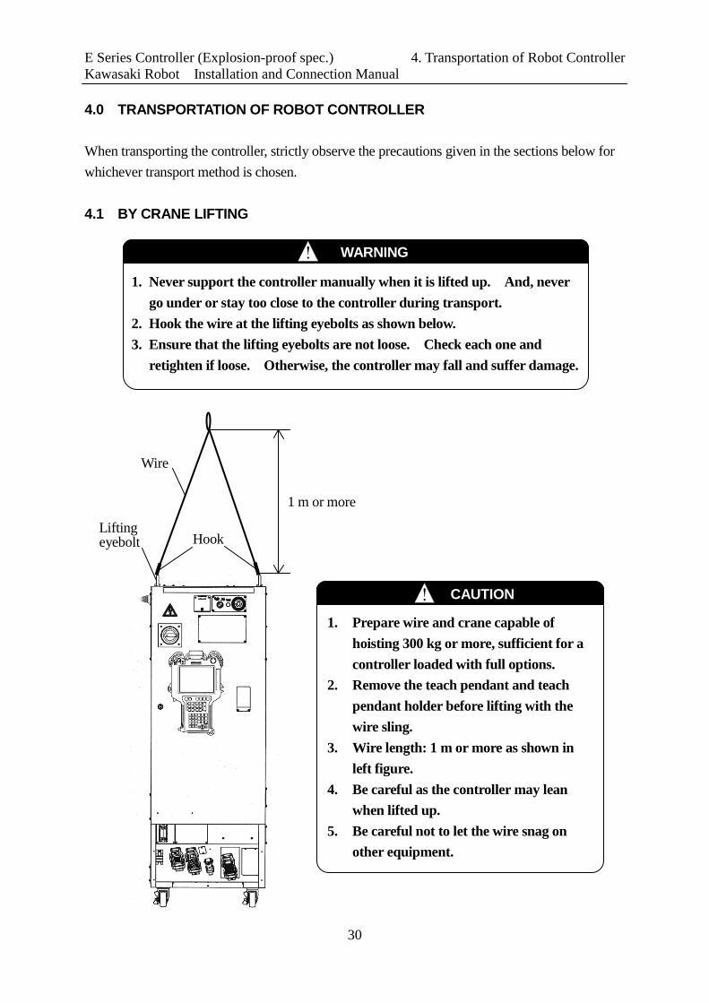
4.0 TRANSPORTATION OF ROBOT CONTROLLER When transporting the controller, strictly observe the precautions given in the sections below for whichever transport method is chosen. 4.1 BY CRANE LIFTING
CAUTION !
1. Prepare wire and crane capable of hoisting 300 kg or more, sufficient for a controller loaded with full options.
2. Remove the teach pendant and teach pendant holder before lifting with the wire sling.
3. Wire length: 1 m or more as shown in left figure.
4. Be careful as the controller may lean when lifted up.
5. Be careful not to let the wire snag on other equipment.
Wire
Lifting eyebolt Hook
1 m or more
1. Never support the controller manually when it is lifted up. And, never go under or stay too close to the controller during transport.
2. Hook the wire at the lifting eyebolts as shown below. 3. Ensure that the lifting eyebolts are not loose. Check each one and
retighten if loose. Otherwise, the controller may fall and suffer damage.
! WARNING
E Series Controller (Explosion-proof spec.) 4. Transportation of Robot Controller Kawasaki Robot Installation and Connection Manual
31
4.2 BY CASTER
1. If the transport path is flat enough then the controller can be moved on its casters. Otherwise, it may happen that moving on an incline or an uneven surface will topple the controller, and cause serious damage.
2. The controller falls if it is inclined as follows. Back or forth: Approx. 10° or more Right or left: Approx. 15° or more
! WARNING
1. Release the stoppers on the two casters in front of the controller when moving the controller. (Push the “OFF” side pedal.)
2. Relock the casters after the transport is complete. (Push the “ON” side pedal for locking.)
! CAUTION
E Series Controller (Explosion-proof spec.) 5. Arrangement of Robot Controller Kawasaki Robot Installation and Connection Manual
32
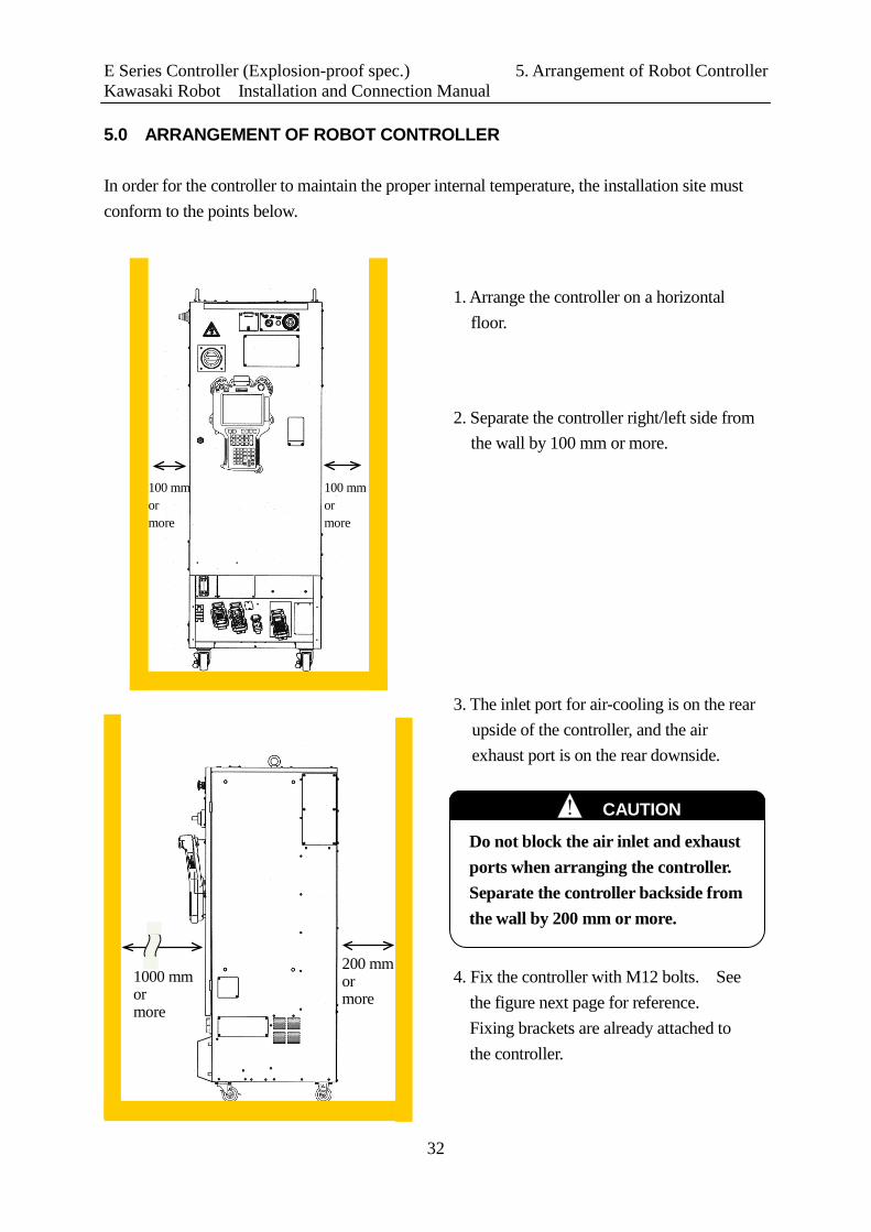
5.0 ARRANGEMENT OF ROBOT CONTROLLER In order for the controller to maintain the proper internal temperature, the installation site must conform to the points below.
2. Separate the controller right/left side from the wall by 100 mm or more.
1. Arrange the controller on a horizontal floor.
100 mm or more
3. The inlet port for air-cooling is on the rear upside of the controller, and the air exhaust port is on the rear downside.
4. Fix the controller with M12 bolts. See the figure next page for reference. Fixing brackets are already attached to the controller.
100 mm or more
200 mm or more
1000 mm or more
Do not block the air inlet and exhaust ports when arranging the controller. Separate the controller backside from the wall by 200 mm or more.
CAUTION !

E Series Controller (Explosion-proof spec.) 5. Arrangement of Robot Controller Kawasaki Robot Installation and Connection Manual
33
M12
Position of anchor to fix brackets
View A-A
1. Release the stoppers on the two casters in front of the controller when moving the controller. (Push the “OFF” side pedal.)
2. Relock the casters after the transport is complete. (Push the “ON” side pedal for locking.)
! CAUTION
A A
! WARNING
Make sure to fix controller with fixing brackets and bolts on the ground.

E Series Controller (Explosion-proof spec.) 6. Connection Instructions Kawasaki Robot Installation and Connection Manual
34
6.0 CONNECTION INSTRUCTIONS 6.1 CONNECTION BETWEEN CONTROLLER AND ROBOT
1. When connecting the harnesses, be sure to use the correct harnesses. Using an incorrect harness, or forcing or misconnecting the harness may damage connectors or cause a break in the electrical system.
2. Prevent people or equipment (forklift, etc.) from stepping on or riding over the signal and motor harnesses. Otherwise, the harness may become damaged or the electrical system may break.
3. Separate the harnesses from any nearby high voltage lines (min. 1 m apart). Do not bundle or run the harnesses in parallel with other power lines. Otherwise, the noise generated from power lines will cause malfunctions.
4. Even when the harnesses are long, do not bundle them winded or bended. Bundling the harness causes the heat to build up in the harness, resulting in over-heat and furthermore may cause fire.
5. Separate the motor harness from the communication and sensor cables, and distribute the lines so they are neither bundled nor running in parallel. Moreover, connect the communication and sensor cables using shield mesh wire that includes twisted pair lines and connect the mesh wires to an adequate FG terminal. Otherwise, PWM noise radiated from the robot’s motor drive lines may penetrate into various cables, such as communication cable and cause communication errors.
6. The motor harness (power line) between the robot and controller will generate PWM noise due to the PWM control driving the motors. This noise may cause interference with signal lines. Prevent interference using these countermeasures:
(1) Separate the power and signal lines as much as possible. (2) Use the shortest possible length for the power line. (3) Avoid bundling, wiring in parallel the power and signal lines as much as
possible. (4) Do not wire the power and signal line within the same duct/conduit. (5) Set and secure a firm earth line connection for the controller.
! CAUTION
! WARNING
Do not connect the external power until connections between controller and robot are complete. Accidents, such as electric shock may occur.

E Series Controller (Explosion-proof spec.) 6. Connection Instructions Kawasaki Robot Installation and Connection Manual
35
Connect the separate harnesses to their designated ports as shown below. Mount the connector cover after connecting the separate harnesses. 1. Controller side
Major axis motor harness (X4)
Signal harness (XE3)
Wrist axis motor harness (X5)
Devicenet harness (XDV)
E27, E37, E47 controller
Connector cover
Purge control unit harness (only XPU, E45)
Motor harness (X4) Signal harness (XE3)
Purge control unit harness (only XPU, E47)
E25, E35, E45 controller
Fix each connector securely. The robot may malfunction if connectors loosen or detach.
CAUTION !
E Series Controller (Explosion-proof spec.) 6. Connection Instructions Kawasaki Robot Installation and Connection Manual
36
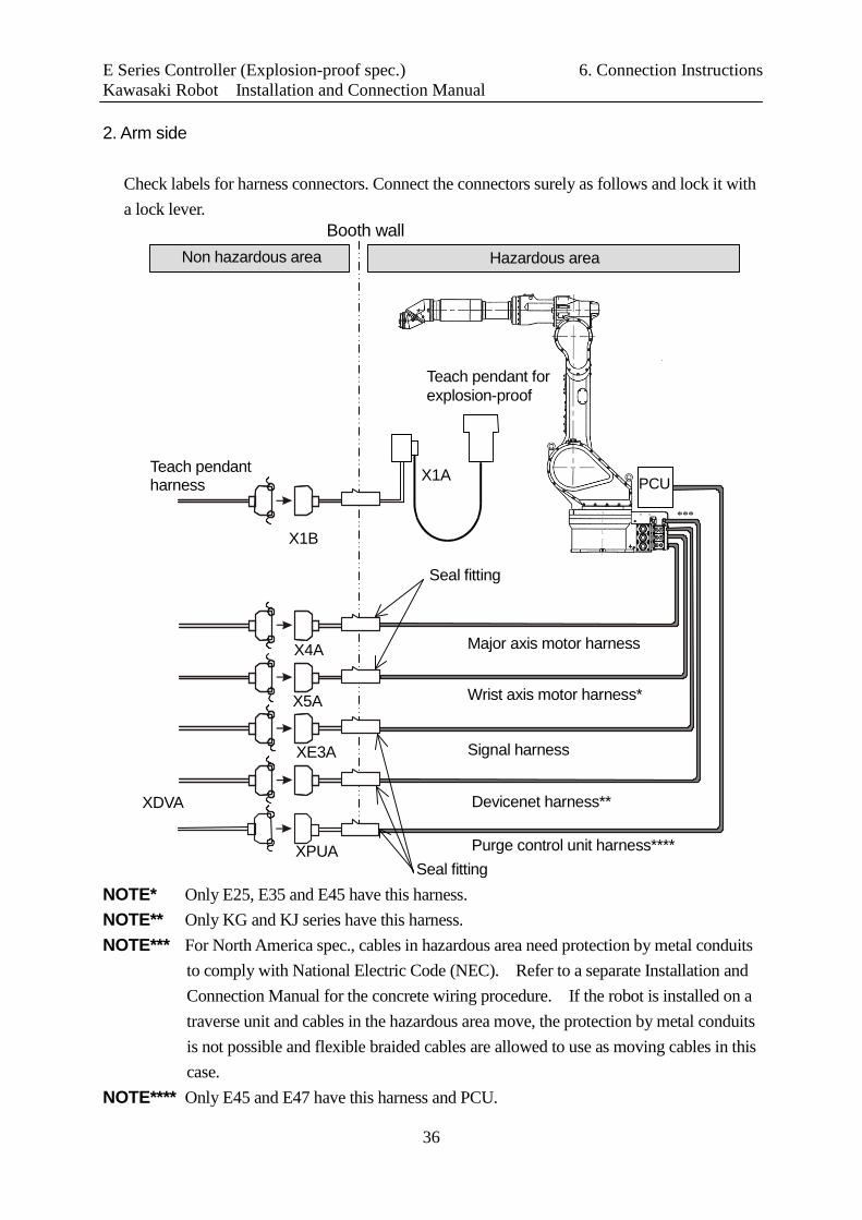
2. Arm side
Check labels for harness connectors. Connect the connectors surely as follows and lock it with a lock lever.
NOTE* Only E25, E35 and E45 have this harness. NOTE** Only KG and KJ series have this harness. NOTE*** For North America spec., cables in hazardous area need protection by metal conduits
to comply with National Electric Code (NEC). Refer to a separate Installation and Connection Manual for the concrete wiring procedure. If the robot is installed on a traverse unit and cables in the hazardous area move, the protection by metal conduits is not possible and flexible braided cables are allowed to use as moving cables in this case.
NOTE**** Only E45 and E47 have this harness and PCU.
XPUA Purge control unit harness****
Major axis motor harness
Wrist axis motor harness*
Seal fitting
X4A
X5A
Signal harness XE3A
XDVA
X1B
X1A
Hazardous area Non hazardous area Booth wall
Teach pendant for explosion-proof
Teach pendant harness
Devicenet harness**
***
PCU
Seal fitting
E Series Controller (Explosion-proof spec.) 6. Connection Instructions Kawasaki Robot Installation and Connection Manual
37
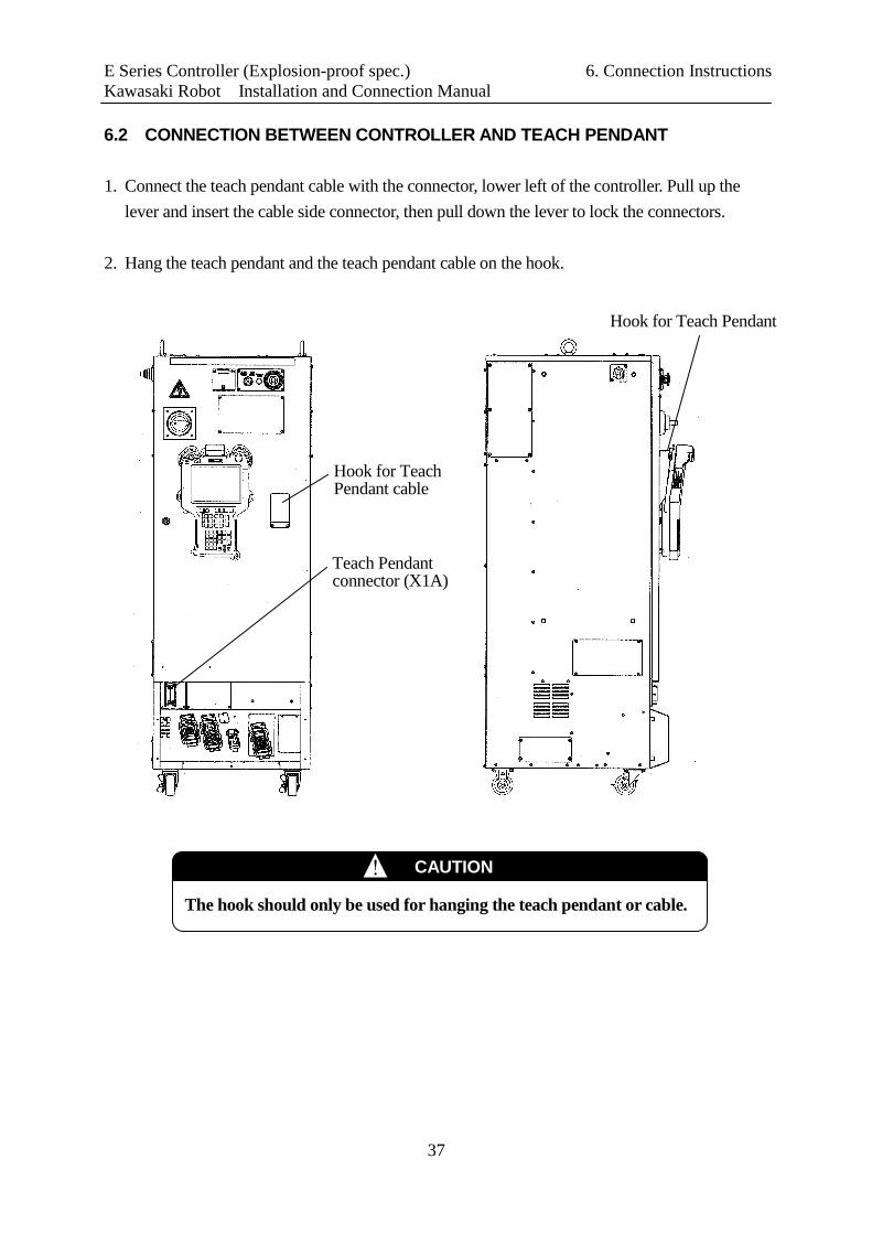
6.2 CONNECTION BETWEEN CONTROLLER AND TEACH PENDANT 1. Connect the teach pendant cable with the connector, lower left of the controller. Pull up the
lever and insert the cable side connector, then pull down the lever to lock the connectors. 2. Hang the teach pendant and the teach pendant cable on the hook.
Hook for Teach Pendant
The hook should only be used for hanging the teach pendant or cable.
CAUTION !
Teach Pendant connector (X1A)
Hook for Teach Pendant cable
E Series Controller (Explosion-proof spec.) 6. Connection Instructions Kawasaki Robot Installation and Connection Manual
38
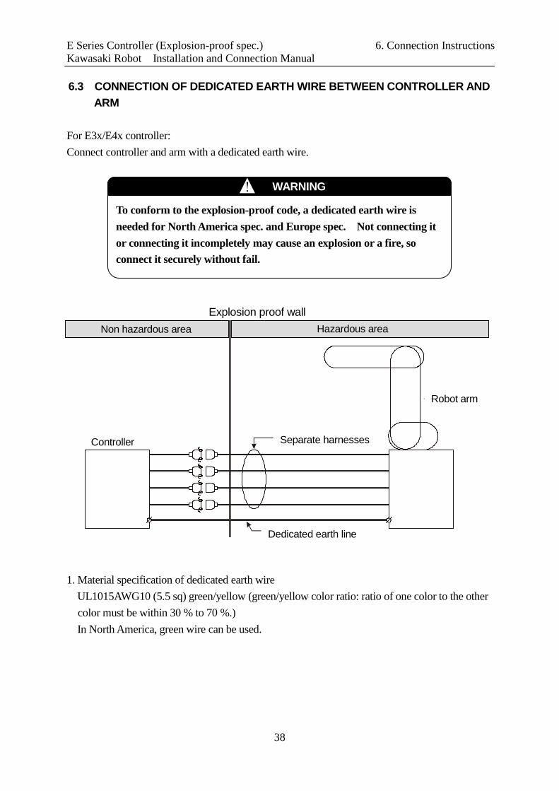
6.3 CONNECTION OF DEDICATED EARTH WIRE BETWEEN CONTROLLER AND ARM
For E3x/E4x controller: Connect controller and arm with a dedicated earth wire.
1. Material specification of dedicated earth wire UL1015AWG10 (5.5 sq) green/yellow (green/yellow color ratio: ratio of one color to the other color must be within 30 % to 70 %.) In North America, green wire can be used.
Dedicated earth line
Controller Separate harnesses
Robot arm
Hazardous area Non hazardous area Explosion proof wall
To conform to the explosion-proof code, a dedicated earth wire is needed for North America spec. and Europe spec. Not connecting it or connecting it incompletely may cause an explosion or a fire, so connect it securely without fail.
WARNING !

E Series Controller (Explosion-proof spec.) 6. Connection Instructions Kawasaki Robot Installation and Connection Manual
39
2. Connection with controller (common for E3x/E4x controller)
Earth wire
Tap
*P=3: Sems screw with spring
M4×8L screw (P=3)

E Series Controller (Explosion-proof spec.) 6. Connection Instructions Kawasaki Robot Installation and Connection Manual
40
3. Connection with arm (1) KF121
NOTE* Insert a flat iron washer between the arm and the earth wire to secure earth and to avoid corrosion.
Flat iron washer*
Tap
Earth wire
M6×20L screw (P=3)
E Series Controller (Explosion-proof spec.) 6. Connection Instructions Kawasaki Robot Installation and Connection Manual
41
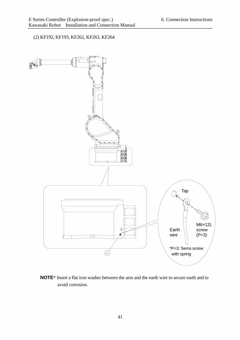
(2) KF192, KF193, KF262, KF263, KF264
NOTE* Insert a flat iron washer between the arm and the earth wire to secure earth and to
avoid corrosion.
M6×12L screw (P=3)
Tap
Earth wire
*P=3: Sems screw with spring
E Series Controller (Explosion-proof spec.) 6. Connection Instructions Kawasaki Robot Installation and Connection Manual
42
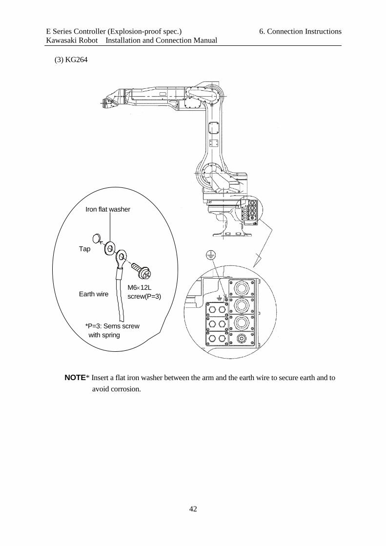
(3) KG264
NOTE* Insert a flat iron washer between the arm and the earth wire to secure earth and to avoid corrosion.
Iron flat washer
Earth wire M6×12L screw(P=3)
Tap
*P=3: Sems screw with spring

E Series Controller (Explosion-proof spec.) 6. Connection Instructions Kawasaki Robot Installation and Connection Manual
43
(4) KJ264 (Floor mounted spec.)
NOTE* Insert a flat iron washer between the arm and the earth wire to secure earth and to avoid corrosion.
*Iron flat washer
M6×12L screw(P=3)
Tap
Earth wire

E Series Controller (Explosion-proof spec.) 6. Connection Instructions Kawasaki Robot Installation and Connection Manual
44
(5) KJ264 (Wall mounted spec., shelf mounted spec.)
NOTE* Insert a flat iron washer between the arm and the earth wire to secure earth and to avoid corrosion.
*Iron flat washer
M6×12L screw(P=3)
Tap
Earth wire
KJ264 Wall mounted (right)
KJ264 Wall mounted (left)
KJ264 Shelf mounted
Enlarged view

E Series Controller (Explosion-proof spec.) 6. Connection Instructions Kawasaki Robot Installation and Connection Manual
45
(6) KJ314
NOTE* Insert a flat iron washer between the arm and the earth wire to secure earth and to avoid corrosion.
*Iron flat washer
M6×12L screw(P=3)
Tap
Earth wire

E Series Controller (Explosion-proof spec.) 6. Connection Instructions Kawasaki Robot Installation and Connection Manual
46
(7)KD010
NOTE* Insert a flat iron washer between the arm and the earth wire to secure earth and to avoid corrosion.
*Iron flat washer
M4×8L screw(P=4)
Tap
Earth wire

E Series Controller (Explosion-proof spec.) 6. Connection Instructions Kawasaki Robot Installation and Connection Manual
47
4. When using metal plate for explosion proof wall
Metal plate explosion proof wall
Screw, etc.
Screw, etc. Stud, tap, etc.
Stud, tap, etc.
To controller
To robot arm
solderless terminal
Solderless terminal

E Series Controller (Explosion-proof spec.) 7. Connection of External Power Kawasaki Robot Installation and Connection Manual
48
7.0 CONNECTION OF EXTERNAL POWER Strictly observe the following precautions when connecting the external power.
Confirm that external power supply for the controller is cut off before starting connection process. Failing to do so is extremely dangerous, resulting in accidents, electric shock, etc. To prevent external power from being turned ON, tag the breaker to indicate clearly that work is in progress. Or, assign a supervisor in front of the breaker until all connections are complete.
DANGER !
1. Make sure the power supply to be connected to the controller meets the specifications listed on the rating plate and label on the side of the breaker. Connecting to a power source outside specifications may damage internal components.
2. Earth the controller to prevent against electrical noise and shock. (For E2x) 2 kinds of dedicated ground lines are required; one with ground resistance 10 Ω or less, important to secure intrinsically safe explosion-proof operation, and another with resistance of 100 Ω or less for general circuit. Be sure to connect each ground line to each specified place without fail. Use earth wire of correct size as shown in 3.3. (For E3x/E4x) Protective earth is required. This is important to secure intrinsically safe explosion-proof operation so connect without fail to the specified place. Use earth wire of correct size as shown in 3.4 and 3.5.
3. Do not use a common earth wire for the controller and the other devices. Also, do not connect earth wires of several controllers to one earth port.
4. Without fail, before turning ON the external power to controller, make sure the power supply wiring is complete and all the covers reattached properly. Failure to do so may cause electric shock.
5. Orange electric cables in the controller are possibly alive even when external power is turned OFF, so be careful.
WARNING !

E Series Controller (Explosion-proof spec.) 7. Connection of External Power Kawasaki Robot Installation and Connection Manual
49
NOTE* Beware that some devices are easily exposed to PWM noise, e.g.: proximity switch
coupled directly to power supply, etc.
CAUTION !
1. Prepare external power that meets the specifications of the controller in terms of momentary power interruption, voltage fluctuation, power capacity, etc. If the power is interrupted or the voltage goes out of the controller’s specified range (above/below ratings), then the power monitoring circuit activates cutting off the power, and an error is returned.
2. If the electrical noise from the peripheral equipments enter via the external power, set up a noise filter to reduce the interference.
3. Likewise, PWM noise coming through the power line from the robot motors may also affect machines with low noise tolerance, resulting in malfunction. Therefore, ensure that there are not such equipments around the controller.
4. Install a separate external power switch (breaker) for the robot, independent and unconnected to peripheral equipments (e.g. weld machine).
5. To prevent shorting or accidental leakage on the external power switch, install an earth leakage breaker. (Use a time delay type with sensitivity of 100 mA or more.)
6. If there is a possibility that surge voltage such as lightning surge might be applied from external power line, decrease the surge voltage level by mounting a surge absorber.

E Series Controller (Explosion-proof spec.) 7. Connection of External Power Kawasaki Robot Installation and Connection Manual
50
1. Connection with external power
Connect with the external power circuit breaker at the installation site.
CONTROLLER POWER switch
External power intake port
Connect the external power according to the following procedure. 1. Turn OFF the external power for the
controller. 2. Set CONTROLLER POWER switch on
the controller door to the OFF side. 3. Feed the external power cable into the
intake port on the left side of controller.
Inside Outside Tightening screw
Lock nut Controller enclosure
Cable
φ9 - 12 φ11 - 14 φ14 - 17 φ17 - 19
Cutting position (φxx: diameter of cable)
Detailed procedure of fixing a cable is shown below. Cut a cable gland (supplied with the controller) in
accordance with the diameter of the cable. Pass the cable through the cable gland. Tighten the screw after adjusting length of the
cable. Pass the cable through the intake port and tighten
the lock nut.
~
~
Cable gland
CAUTION
1. Confirm current requirements and select a power cable with adequate capacity. (See section 3.0.)
2. Do not install wire that is too small in diameter, the voltage may drop or the cable may overheat.
E Series Controller (Explosion-proof spec.) 7. Connection of External Power Kawasaki Robot Installation and Connection Manual
51
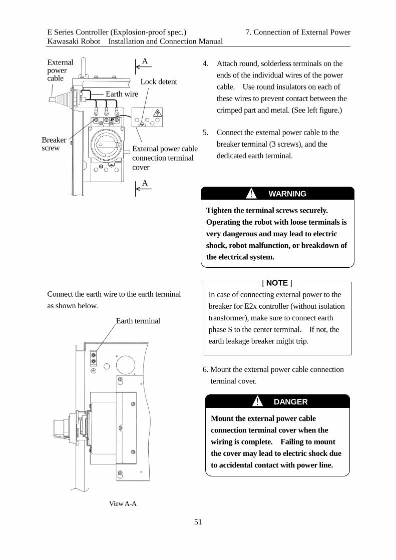
Connect the earth wire to the earth terminal as shown below.
4. Attach round, solderless terminals on the ends of the individual wires of the power cable. Use round insulators on each of these wires to prevent contact between the crimped part and metal. (See left figure.)
5. Connect the external power cable to the
breaker terminal (3 screws), and the dedicated earth terminal.
WARNING !
Tighten the terminal screws securely. Operating the robot with loose terminals is very dangerous and may lead to electric shock, robot malfunction, or breakdown of the electrical system.
Breaker screw
Earth wire
External power cable Lock detent
External power cable connection terminal cover
A
A
View A-A
! DANGER
Mount the external power cable connection terminal cover when the wiring is complete. Failing to mount the cover may lead to electric shock due to accidental contact with power line.
6. Mount the external power cable connection terminal cover.
In case of connecting external power to the breaker for E2x controller (without isolation transformer), make sure to connect earth phase S to the center terminal. If not, the earth leakage breaker might trip.
[ NOTE ]
Earth terminal

E Series Controller (Explosion-proof spec.) 7. Connection of External Power Kawasaki Robot Installation and Connection Manual
52
2. Connection to earth for intrinsically safe circuit (E2x controller only)
For E2x controller, connect the earth wire to the terminal block for connection to earth for intrinsically safe circuit with resistance under 10 Ω as shown in the figure below.
Terminal block for connection to ground for intrinsically safe circuit
! WARNING
Be sure to execute connection to ground to ensure intrinsically safe operation without fail.

E Series Controller (Explosion-proof spec.) 8. Connection of Peripheral Kawasaki Robot Installation and Connection Manual Control Equipment
53
8.0 CONNECTION OF PERIPHERAL CONTROL EQUIPMENT According to application specifications, connect respective connectors in the controller shown below with the peripheral controller or devices. See the upper right figure for details on connecting ports of 1TA/1VA board. NOTE*: The upper RS-232C port and the upper USB port are connected to the each port in the
accessory panel for standard specification.
Terminal block X7 connector Terminal block X8 connector
Terminal block X9 connector
1TW board 1TR board
External D-I/O connector CN4 (Input)
External D-I/O connector CN2 (Output)
Cable support
Upper part of the inside
Cable support
1TA/1VA board
1TA/1VA board
RS-232C port*
USB port* Ethernet
port
Use cable support for wiring of 24Vdc or less such as I/O, Ethernet and fieldbus cable, etc. Make sure not to put any stress on connectors on each board. Screw to connect
external I/O cable shield (M4)

E Series Controller (Explosion-proof spec.) 8. Connection of Peripheral Kawasaki Robot Installation and Connection Manual Control Equipment
54
8.1 INSTRUCTIONS AT THE CONNECTION
WARNING !
Turn OFF the power supply to the controller and peripheral equipment when connecting external I/O. Prevent accidental turn ON of the power until all connections are complete by tagging the breaker to indicate that work is in progress or by assigning a supervisor to stand in front of the breaker. Failure to do so is extremely dangerous and may result in electric shock or damage to the electrical system.
CAUTION !
1. Take the necessary noise countermeasures on equipment with external I/O connections to the controller. Electrical noise that interferes with the I/O signals may cause malfunction or damage to the electrical system.
2. Do not mistake pin Nos. on the connectors when connecting external I/O. Misconnecting pins may cause breakdown of the electrical system.
3. Prevent people or equipment (forklift, objects, etc.) from stepping on or riding over the external I/O cables. An unprotected cable may become damaged causing breaks in the electrical system.
4. Avoid wiring the external I/O cables and the power lines close together or in parallel as much as possible. Separate the cables and lines by at least 20 cm (either in or outside the controller). Electromagnetic induction noise from the robot motor cable, the power lines for peripheral equipment, welding cable, etc. may penetrate into the I/O cables and lead to malfunction.
5. Use a shield cable for the external I/O cable and connect the shield wire to the controller.
6. When connecting I/O cables to connectors or terminals, fix them with tying bands in the cable support set on the top of the controller, preventing them from excessive force. (pulling, snagging of cable, etc.)
7. Install the seal connector so that external I/O cables never cause insulation failure or disconnection at the intake port.
E Series Controller (Explosion-proof spec.) 8. Connection of Peripheral Kawasaki Robot Installation and Connection Manual Control Equipment
55
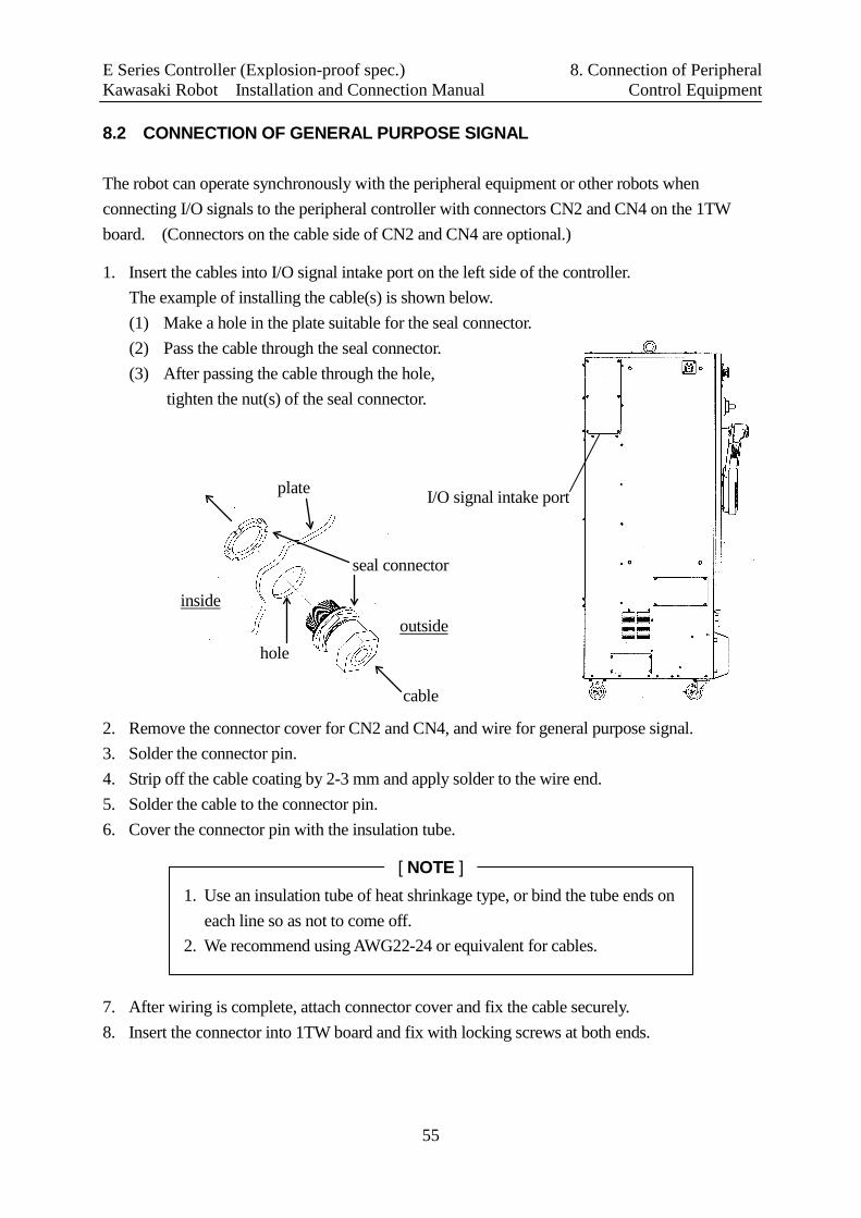
8.2 CONNECTION OF GENERAL PURPOSE SIGNAL The robot can operate synchronously with the peripheral equipment or other robots when connecting I/O signals to the peripheral controller with connectors CN2 and CN4 on the 1TW board. (Connectors on the cable side of CN2 and CN4 are optional.)
1. Insert the cables into I/O signal intake port on the left side of the controller. The example of installing the cable(s) is shown below. (1) Make a hole in the plate suitable for the seal connector. (2) Pass the cable through the seal connector. (3) After passing the cable through the hole,
tighten the nut(s) of the seal connector. 2. Remove the connector cover for CN2 and CN4, and wire for general purpose signal. 3. Solder the connector pin. 4. Strip off the cable coating by 2-3 mm and apply solder to the wire end. 5. Solder the cable to the connector pin. 6. Cover the connector pin with the insulation tube. 7. After wiring is complete, attach connector cover and fix the cable securely. 8. Insert the connector into 1TW board and fix with locking screws at both ends.
I/O signal intake port
cable
seal connector
plate
hole outside
inside
1. Use an insulation tube of heat shrinkage type, or bind the tube ends on each line so as not to come off.
2. We recommend using AWG22-24 or equivalent for cables.
[ NOTE ]

E Series Controller (Explosion-proof spec.) 8. Connection of Peripheral Kawasaki Robot Installation and Connection Manual Control Equipment
56
8.3 CONNECTION OF HARDWARE DEDICATED SIGNAL It is possible to construct a safety circuit using the hard circuit by connecting the external emergency stop signal or hold signal line to the terminal connector on the 1TR board. Refer to “External I/O Manual” for more details about signals and their connection to each terminal block. We recommend using AWG22-24 or equivalent for cables. (Stripped wire length: 7 mm) To assure the wiring, we recommend using ferrules; Recommended model: 216-201 (WAGO) Recommended crimping tool: 206-204 (WAGO) (Stripped wire length: 9.5 mm)
Terminal block connections are held in place by springs. Push a thin flat-head screwdriver (width: 2.5 mm or less) into the hole on the right to open spring in the left hole. Then insert the wire there for connection.
Connector CN2 17JE-13370-02(D1)A(DDK) or equivalent CN4 17JE-23370-02(D1) (DDK) or equivalent
Stripped wire 2-3 mm
Connector pin
Cable
Insulation tube
1TR Board
X7 Connector (X8 Connector) (X9 Connector)
Connection side
Insert driver for connection
Cover 17JE-37H2-1A-CF(DDK) or equivalent
Tighten the screw thoroughly. If the screw is loose, the connector pins may be exposed to force beyond standard and that may lead connection failure.
[ NOTE ]
E Series Controller (Explosion-proof spec.) 8. Connection of Peripheral Kawasaki Robot Installation and Connection Manual Control Equipment
57
8.4 CONNECTION OF PERSONAL COMPUTER It is possible to use a PC as terminal for the robot controller, when connecting a PC loaded with KRterm/KCwin32 software to the RS-232C port in the accessory panel. It is also possible to do so, when connecting a PC loaded with KCwin/KRterm software to the Ethernet port on 1TA/1VA board using Ethernet cable. Refer to “AS Language Reference Manual” for more details. 8.5 CONNECTION OF RS-232C SERIAL SIGNAL (OPTION) Data communication is possible between the host computer and 1TA/1VA board, when connecting to the RS-232C port on the 1TA/1VA board with an RS-232C cable. Refer to option manual 90210-1177DE* for details. 8.6 CONNECTION OF ETHERNET COMMUNICATION SIGNAL (OPTION) It is possible to build an Ethernet LAN of 10BaseT/100BaseTX using the Ethernet port on the 1TA/1VA board. Because cables differ according to each application specification, refer to option manual 90210-1248DE* for details. 8.7 CONNECTION OF FIELDBUS (OPTION) Adding the 1TJ/1UK board for fieldbus (option) enables communication with peripheral devices on the fieldbus such as DeviceNet. Refer to option manual 90210-1184DE* for details.
E Series Controller (Explosion-proof spec.) Kawasaki Robot Installation and Connection Manual
58
E Series (Explosion-proof type) INSTALLATION AND CONNECTION MANUAL
February 2009 : 1st Edition July 2015 : 7th Edition
Publication : KAWASAKI HEAVY INDUSTRIES, LTD.
90202-1111DEG
Copyright 2015 KAWASAKI HEAVY INDUSTRIES, LTD. All rights reserved.