Embed Size (px)
Citation preview

De
part
men
t of N
atur
al R
esou
rces
and
Min
es
Legal Traceability of Length for EDME EDME Comparison Procedure
Version 1.0

Revision History
Version Date Amended By Notes
1.0 22-08-2012 I Stiller Initial version created
1.01 18-4-2013 B Cowie Review
Document Acceptance
Position Name Signature Date
Director, Cadastral and Geodetic Services Russell Priebbenow
Prepared by: Geodesy and Positioning, Land and Spatial Information Department of Natural Resources and Mines This document has been prepared with all due diligence and care, based on the best available information at the time of publication. The department holds no responsibility for any errors or omissions within this document. Any decisions made by other parties based on this document are solely the responsibility of those parties. Information contained in this document is from a number of sources and, as such, does not necessarily represent government or departmental policy. © State of Queensland, Department of Natural Resources and Mines, 2012. The Queensland Government supports and encourages the dissemination and exchange of its information. The copyright in this publication is licensed under a Creative Commons Attribution 3.0 Australia (CC BY) licence.
Under this licence you are free, without having to seek permission from DNRM, to use this publication in accordance with the licence terms. You must keep intact the copyright notice and attribute the State of Queensland, Department of Natural Resources and Mines as the source of the publication. For more information on this licence visit http://creativecommons.org/licenses/by/3.0/au/deed.en
Legal Traceability of Length for EDME – CBD/041230.LTOLE_EDME_Comparison_Procedure.1.0 2

Contents
1. LEGAL TRACEABILITY OF LENGTH ....................................................................................................................... 6
1.1. BACKGROUND ...................................................................................................................................................... 6 1.2. DEPARTMENTAL POLICY (SIG/2010/4034) – SERVICE FOR LEGAL TRACEABILITY ............................................................. 6
Rationale ..................................................................................................................................................... 7 1.2.1. Policy ........................................................................................................................................................... 7 1.2.2.
2. QUEENSLAND EDM BASELINES .......................................................................................................................... 8
2.1. PURPOSE ............................................................................................................................................................ 8 2.2. CORRECTIONS ...................................................................................................................................................... 8 2.3. DESIGN ............................................................................................................................................................... 8
3. ERRORS AND UNCERTAINTIES ........................................................................................................................... 9
3.1. BASELINE MONUMENTS ......................................................................................................................................... 9 Regulation 13 certified values (Distance, Offset and Reduced Level) ......................................................... 9 3.1.1. Movement of baseline monuments ............................................................................................................ 9 3.1.2.
3.2. EDME SETUP AND CAPABILITY .............................................................................................................................. 10 Centring and levelling over the monument ............................................................................................... 10 3.2.1. Prism ......................................................................................................................................................... 10 3.2.2. EDM Instrument settings .......................................................................................................................... 11 3.2.3.
3.3. ATMOSPHERIC CONDITIONS AND METEOROLOGICAL OBSERVATIONS (METS) ................................................................. 11 Temperature ............................................................................................................................................. 11 3.3.1. Pressure ..................................................................................................................................................... 12 3.3.2. Relative Humidity ...................................................................................................................................... 12 3.3.3. Atmospheric uniformity assumption ......................................................................................................... 12 3.3.4.
3.4. HUMAN ERROR .................................................................................................................................................. 13
4. EDME COMPARISON .........................................................................................................................................14
4.1. OFFICE PROCEDURES (PRE-FIELD) .......................................................................................................................... 14 Equipment Checks ..................................................................................................................................... 14 4.1.1.
4.1.1.1. Calibration ........................................................................................................................................................14 4.1.1.2. Condition: .........................................................................................................................................................15 4.1.1.3. Availability: .......................................................................................................................................................15
Personnel Checks ....................................................................................................................................... 16 4.1.2.4.1.2.1. Assistance: ........................................................................................................................................................16
Baseline Access Requirements: ................................................................................................................. 16 4.1.3. Documentation ......................................................................................................................................... 17 4.1.4.
4.2. FIELD PROCEDURES ............................................................................................................................................. 17 Setup and Inspection ................................................................................................................................. 18 4.2.1. Observations ............................................................................................................................................. 19 4.2.2.
4.2.2.1. Sequence Pattern .............................................................................................................................................19 4.2.2.2. Sequence Observations ....................................................................................................................................19 4.2.2.3. Remote Mets ....................................................................................................................................................21
Checks and pack up ................................................................................................................................... 23 4.2.3.4.3. OFFICE PROCEDURES (POST-FIELD) ........................................................................................................................ 24
EDME Comparison Software ..................................................................................................................... 24 4.3.1.4.3.1.1. Download Instructions:.....................................................................................................................................24 4.3.1.2. Software Instructions: ......................................................................................................................................24 4.3.1.3. Software Support: .............................................................................................................................................25
4.4. COMPARISON REPORTS ........................................................................................................................................ 25
Legal Traceability of Length for EDME – CBD/041230.LTOLE_EDME_Comparison_Procedure.1.0 3

Instrument Correction Values ................................................................................................................... 25 4.4.1.4.4.1.1. Assessment and Analysis of Results ..................................................................................................................26
4.5. RECORD KEEPING ............................................................................................................................................... 26
5. DEFINITIONS .....................................................................................................................................................27
6. REFERENCES .....................................................................................................................................................29
APPENDIX A REGULATION 13 EDM BASELINES ...................................................................................................30
APPENDIX B SEQUENCE PATTERNS .....................................................................................................................31
APPENDIX C EXAMPLE BOOKING SHEET EXTRACT ..............................................................................................32
Legal Traceability of Length for EDME – CBD/041230.LTOLE_EDME_Comparison_Procedure.1.0 4

About this Procedure Document
In accordance with Regulation 73 of National Measurement Regulations 1999 (Cwlth), in force under the National Measurement Act 1960 (Cwlth), hereafter referred to as the Act, the Department of Natural Resources and Mines (DNRM), hereafter referred to as the department, is appointed as a Verifying Authority for the verification and re-verification of the physical quantity length. As a prerequisite for appointment as a Verifying Authority, the department is formally accredited by the National Association of Testing Authorities (NATA) for its technical competence in providing calibration services in accordance with the requirements of AS ISO/IEC 17025:2005 General Requirements for the Competence of Testing and Calibration Laboratories, hereafter referred to as ISO/IEC 17025 or the ISO Standard.
The department is committed to achieving a high standard of quality in all aspects of its Electronic Distance Measurement (EDM) baseline calibration and instrument comparison activities, in order to provide legal traceability of length for surveying EDM equipment (EDME). The department is also committed to maintaining its technical competency in these areas as per the requirements and procedures described in ISO/IEC 17025 and the NATA Field Application Document (FAD) for Measurement Science and Technology. Under Section 21 of the Survey and Mapping Infrastructure Regulation 2004, Queensland surveyors have an obligation to ensure that any survey equipment (or EDME) used for cadastral surveys is calibrated and standardised. This procedure is intended for Queensland surveyors requiring legal traceability for their EDME measurements. It will define the department’s recommended procedure for carrying out an EDME comparison, in order to achieve legal traceability. This procedure is designed for surveying EDM total stations only, and as such does not accommodate for laser scanners, offset/cloth tapes, handheld distance meters, or GNSS equipment. Further information relating to the technical content in this procedure can be found in J.M Rüeger 1989: Electronic Distance Measurement – An Introduction (hereafter referred to as Rüeger’s book). To avoid duplication of content, this procedure shall refer to Rüeger’s book where appropriate.
Legal Traceability of Length for EDME – CBD/041230.LTOLE_EDME_Comparison_Procedure.1.0 5

1. Legal Traceability of Length
1.1. Background
Under Section 21 of the Survey and Mapping Infrastructure Regulation 2004, Queensland surveyors are required to standardise and calibrate their EDM instruments if used for cadastral surveys. The validity of these measurements will be strengthened if questioned in a court of law provided that the instrument is proven to be traceable to the national standard.
It is not practical for Queensland surveyors to send their EDM instruments to the National Measurement Institute for calibration and standardisation. As a result of this, the department assumes the responsibility of providing the means for Queensland surveyors to carry out such activities by becoming a Verifying Authority for length under the National Measurement Regulations 1999 (Cwlth). For Queensland surveyors, traceability of length for their survey EDME measurements can be achieved if:
1. the measurements are made by an appropriate EDM instrument that has been tested according to the recommended procedure on an EDM baseline
2. at the time of testing, the EDM baseline used held a current and valid Regulation 13 Certificate issued by the relevant Verifying Authority
3. the EDM Baseline holding a Regulation 13 Certificate was calibrated by the State EDM Calibration Officer (SCO) according to the approved procedures, and using the designated EDM baseline calibration instrument
4. the EDM baseline calibration Instrument and supporting meteorological instruments used by the SCO holds a valid and current calibration certificate issued by the appropriate Verifying Authority.
Provided the above criteria are met, traceability achieved through this procedure will be in the form of a comparison report generated by the software used to process the field observations. For more information on the reports generated, see section 4.4.
1.2. Departmental Policy (SIG/2010/4034) – Service for Legal Traceability
The focus of this departmental policy is to provide a service that gives legal traceability of length to the national standard for distance measurements made using electronic distance measurement equipment (EDME).
Legal Traceability of Length for EDME – CBD/041230.LTOLE_EDME_Comparison_Procedure.1.0 6

Rationale 1.2.1.
Section 21 of the Survey and Mapping Infrastructure Regulation 2004 requires surveyors to ensure their equipment is calibrated and standardised. The department therefore offers a service to enable surveyors to validate the traceability of their equipment to the national standards.
The service is based on the department being appointed as a Verifying Authority for length under the provisions on the National Measurement Act 1960 (Cwlth).
The department is formally appointed as a Verifying Authority for length by the National Measurement Institute (NMI). As a prerequisite for appointment as a Verifying Authority, the department is assessed for its technical competence in providing calibration services by the National Association of Testing Authorities (NATA), in accordance with the requirements of AS ISO/IEC 17025:2005 General Requirements for the Competence of Testing and Calibration Laboratories.
Policy 1.2.2.
The department will maintain its appointment as a Verifying Authority for length with the National Measurement Institute.
The department will continue to provide and maintain the infrastructure and procedures that are necessary for the community to achieve legal traceability for their EDME. This will be carried out through two services:
a. Baseline calibration The department will maintain certification of approved baselines, in accordance with Regulation 13 of the National Measurement Regulation 1999 (Cwlth).
The department may certify any approved non-departmental baselines and reserve the right to recover costs.
The department will respond accordingly to reported instability or disturbance to the monuments of approved baselines.
b. EDME traceability
The department will ensure that both the approved software and the recommended procedures are made available to the community for the purposes of achieving traceability of length for EDME.
Legal Traceability of Length for EDME – CBD/041230.LTOLE_EDME_Comparison_Procedure.1.0 7

2. Queensland EDM Baselines
2.1. Purpose
EDM baselines are designed to be cost effective infrastructure used for testing surveying EDME. The testing of EDME on an EDM baseline constitutes multiple distance observations, along with the associated meteorological observations, being processed in a constrained adjustment against the Reference Standard (Regulation 13 Certificate values for that baseline) to produce instrument correction values that describe the relationship between the measurements of the instrument being tested and the Reference Standard. In Queensland, this testing procedure is referred to as an EDME comparison.
A list of all the baselines that are periodically calibrated by the department is found in Appendix A.
2.2. Corrections
The key instrument corrections that are determined in an EDME comparison are the additive constant and scale factor. In addition to the additive constant and scale factor, EDME has traditionally been tested for the cyclic error, although with the improved technology in modern instruments, the cyclic error has been proven to have an insignificant effect and consequently is not required to be determined as part of EDME testing. For more information regarding the instrument corrections, refer to Rüeger’s book.
2.3. Design
The design of EDM baselines can vary according to the type of instruments that it is intended to support, primarily for the determination of the cyclic error. Because cyclic error is not critical to an EDME, the majority of EDM baselines in Queensland are based on a 7 station Schwendener style design. Approximately half of the baselines are pillared.
For more information on the baselines in Queensland, see the relevant EDM baseline information documents found on the department’s webpage for legal traceability of length1.
For more information regarding baseline design, refer to Rüeger’s book.
1 Legal traceability webpage <http://www.nrm.qld.gov.au/property/surveying/legal-traceability/index.html>
Legal Traceability of Length for EDME – CBD/041230.LTOLE_EDME_Comparison_Procedure.1.0 8

3. Errors and Uncertainties
All errors fall into one of three categories:
1. gross errors
2. systematic errors
3. random errors.
The general rule with errors is that every effort should be made to identify and eliminate gross errors, correct for systematic errors, and if random errors don’t cancel each other out they should be adjusted.
A satisfactory comparison on an EDM baseline requires error and uncertainty to be eliminated wherever possible. In some instances, error cannot be eliminated and should be minimised as much as possible to ensure quality results are achieved.
With any comparison, the extent to which errors and uncertainties are controlled or reduced is determined by the capability and limitations of the instrument being tested. For example, high precision EDME should be tested on a pillared baseline and taking more rigorous meteorological observations. Alternatively, for low precision EDME the use of a ground mark baseline and the minimum meteorological observations may suffice. The following sections describe the more common areas of errors and uncertainty that may be encountered whilst undertaking an EDME comparison.
3.1. Baseline monuments
Regulation 13 certified values 3.1.1. (Distance, Offset and Reduced Level)
These values are determined by measurements which themselves have associated uncertainties.
A uniform uncertainty for all Regulation 13 certified distances on each baseline is stated as 0.5 mm + 1.3 PPM, as determined by a rigorous calculation of the estimated measurement uncertainty (or uncertainty budget) for the procedure employed for baseline calibrations in Queensland. Offsets and reduced levels are both estimated to have an uncertainty of ± 5mm. This uncertainty is known to contribute very little towards the final uncertainty of the distance.
Movement of baseline monuments 3.1.2.
All baseline monuments are susceptible to movement and the magnitude of this movement varies depending on location, weather and the potential of physical disturbance. Without regular calibrations, it is difficult to precisely determine the magnitude of the movement that baseline monuments experience. Because of this, persons undertaking an EDME comparison should be aware of the potential uncertainty associated with movement of baseline monuments.
Legal Traceability of Length for EDME – CBD/041230.LTOLE_EDME_Comparison_Procedure.1.0 9

Baselines that are known to be stable have consistently shown movement of less than 2mm between calibrations (every two years), whereas monuments on baselines affected by instability have shown up to 20mm of movement between calibrations.
It is advised that persons undertaking an EDME comparison be aware of the potential movement that their chosen baseline may experience. In any case this uncertainty can be avoided or significantly reduced by testing EDME on a baseline immediately after it has been calibrated. The longer the duration between the baseline calibration and an EDME comparison, the greater the uncertainty associated with monument movement.
3.2. EDME setup and capability
Centring and levelling over the monument 3.2.1.
Centring and levelling is the most significant of all areas of uncertainty. Any error in centring and levelling the tribrachs will contribute directly to the error in the distance measurements, thus increasing the total uncertainty of the test result. Choosing a pillared baseline for the EDME comparison largely eliminates centring errors and significantly reduces levelling errors. Extra care should be taken when centring and levelling tribrachs on ground mark (non-pillared) monuments. In any case, the best seven tribrachs that are available should be chosen and if possible they should be identical. This is paramount as uncertainty may be introduced by having different tribrachs and also by having to move and reset tribrachs on more than one monument midway through the comparison.
Prior to performing an EDME comparison each tribrach should be checked for the following to ensure they are accurate, in good condition and suitable for use:
• Optical plummet should be clear and accurate. It is preferable to use an optical plummet with the ability to rotate through 180°, as any error can be identified and adjusted easily.
Ensure there is no looseness or slack in any part of the tribrach that is not meant to have it.
• Condition of the level bubble should be assessed and also checked against another levelling device or levelled surface. Similar to the optical plummet, it is preferable to use a plate level bubble (being more accurate) which rotates through 180° so that errors can be easily identified and adjusted.
Prism 3.2.2.
It is important to select a prism that is designed for the EDM instrument being tested, particularly for precise distance measurement. Different prisms produced are designed for a particular use. Generally the prism that allows the most precise distance measurements will be the circular (or round) prisms made by the respective manufacturer. Some manufacturers produce a precise prism which is similar to the circular prisms in style, and if this is available it should be used. Regardless of which prism is used, it must be in good condition and reliable. Mini prisms and 360° prisms
Legal Traceability of Length for EDME – CBD/041230.LTOLE_EDME_Comparison_Procedure.1.0 10
should be avoided as they tend to be less precise, and return less signal strength than circular prisms.
EDM Instrument settings 3.2.3.
Most EDM instruments have specific modes of measurement to allow for different applications. Some of these modes are precise, rough, tracking and automatic target recognition (ATR), each of which should have a corresponding precision to which distance can be measured. The most precise measurement mode must be used so that the full capability of the instrument can be tested. Commonly the most precise measurement mode is labelled accordingly (precise mode). Tracking and coarse measurement mode should never be used while testing an EDM instrument, as these will often reduce the precision of distance measurement.
Depending on the instrument, features such as ATR that do not impact on the precision of the distance measurement, should be used where appropriate. ATR will search and lock onto the highest return signal strength, being the prism. This mode, although not increasing the precision of distance measurement, will save time by not having to manually turn the instrument sights onto the prism and checking the signal strength. This will also reduce any error related to pointing at different parts of the prism and trouble with sighting through heat haze.
EDM instruments should also be set to display distances in metres and to four decimal places rather than three. A rounding error of up to 0.5 mm is introduced if distances are measured to the nearest millimetre. By taking multiple distance measurements (10) for each sequence, this error usually cancels itself out, however the best practice is to measure distances to the next decimal place to what accuracy is sought after.
3.3. Atmospheric Conditions and Meteorological Observations (Mets)
Observing and correcting for atmospheric conditions is the most common source of error that is likely to be encountered during an EDME comparison. Consequently, it is critical that meticulous atmospheric observations are taken so that correction can be made due to atmospheric conditions.
Temperature, pressure and relative humidity must be observed as they are the three atmospheric conditions that influence the distance measured.
See sections 5.5 to 5.8 of Rüeger’s book for more detailed information regarding atmospheric corrections and errors.
Temperature 3.3.1.
Temperature is the most significant of the three atmospheric conditions and is most likely to be a source of error if not observed correctly. This is largely due to the more direct influence it has on the distance measurement. It is also because the temperature is more likely to fluctuate throughout the duration of the comparison than pressure or relative humidity. Temperature is also the meteorological condition most likely to vary from one end of the baseline to the other.
Legal Traceability of Length for EDME – CBD/041230.LTOLE_EDME_Comparison_Procedure.1.0 11

For high precision instruments, temperature should be observed at both ends of the line being measured to determine the average temperature.
An error of 1 °C in temperature observations translates to a 1 PPM error in the corrected distance. Therefore it is important to have an accurate and precise thermometer for measuring temperature, especially when testing high precision EDM instruments. (1 °C = 1 PPM)
It is recommended that the minimum accuracy for thermometers used should be ± 0.5 °C. The instrument should be compared against a reliable and independent thermometer prior to use.
Pressure 3.3.2.
Of the three atmospheric conditions corrected for, pressure is the least likely to change rapidly and will be the most consistent across the baseline.
An error of 1 millibar in pressure observations translates approximately to a 0.3 PPM error in the corrected distance. (1 mb ≈ 0.3 PPM) It is recommended that the minimum accuracy for barometers used should be ± 1 mb. The instrument should be compared against a reliable and independent barometer prior to use.
Relative Humidity 3.3.3.
Relative humidity can fluctuate very rapidly in coastal regions due to humid sea breezes. However relative humidity has the least influence on the distance of the three atmospheric conditions which are corrected for in an EDME comparison.
The error in the corrected distance associated with relative humidity is dependent on both the magnitude of the relative humidity and the temperature at the time of measurement.
Section 5.8.5 of Rüeger’s book indicates that if relative humidity is measured to an accuracy of ± 3% and temperature is measured to an accuracy of ± 0.2 °C, then the error in the corrected distance (depending on the temperature) is expected be less than 0.1 PPM. While this may seem insignificant, if no correction for relative humidity is made the measured distance may be in error of up to 2 PPM. Therefore relative humidity must be observed and corrected for, although not as accurately as temperature or pressure. (0.02 PPM < ± 3 %RH & ± 0.2 °C < 0.1 PPM)
It is recommended that the minimum accuracy for hygrometers (or other relative humidity measuring instruments) used should be ± 3 %. The instrument should be compared against a reliable and independent source prior to use.
Atmospheric uniformity assumption 3.3.4.
When measuring any distance, there is an assumption that the atmospheric conditions at one end of the line measured is the same as the other end. This assumption may be sound enough for distances that are relatively short; however on the longer lines this assumption can introduce significant uncertainty.
As mentioned previously the temperature and relative humidity are most likely to vary across the line measured. However because relative humidity influences the distance less than temperature,
Legal Traceability of Length for EDME – CBD/041230.LTOLE_EDME_Comparison_Procedure.1.0 12

it is not considered to contribute much to the uncertainty caused by the atmospheric uniformity assumption.
As part of the baseline calibration procedure employed by the department, atmospheric observations are taken every 30 seconds at both ends and in the middle of the baseline. From analysing this data, the average variation in temperate from one end of a baseline to another, is approximately 1 °C which results in a 1 PPM error in the distance as a result of the atmospheric uniformity assumption. On occasion, the difference in temperature has been known to reach 2 °C which also results in an error of 2 PPM.
Typically atmospheric conditions are observed at the EDM instrument only, but in order to reduce the error associated with this assumption; the only practical solution is to observe atmospheric conditions at the prism as well. This is commonly referred to as “remote meteorological observations” or “remote mets”.
It is recommended that every EDME comparison incorporates remote mets to assist in reducing the uncertainty associated with the atmospheric uniformity assumption, especially when testing higher precision EDM instruments.
As mentioned previously, the uncertainty of this assumption increases with longer distances. As a general guide, distances less than 100m should not need remote mets; however discretion should be used as this may depend on the characteristics of the baseline (i.e. a mix of shaded and unshaded areas across the baseline which create air pockets of different air temperatures). Another assumption is made regarding atmospheric uniformity and does not relate to the length of the line measure. This assumption is made when measuring a distance multiple times over a period of time. A set of 10 distance measurements are made in each sequence, typically being taken over a duration of one to two minutes. Over this short time, fluctuations in temperature of 2 °C and 10% in relative humidity have been observed in the baseline calibration atmospheric observation datasets. These variations are generally caused by cloud movement and sea breezes. As was the case earlier, relative humidity is regarded not to contribute significantly to this uncertainty. However without taking multiple temperature observations in each sequence, this assumption can result in an uncertainty of up to 2 PPM in the measured distance. It is recommended that for each sequence (set of 10 distance measurements), three temperature observations are made (start, middle and end), to determine a true and accurate indication of the temperature for the period of measurement.
3.4. Human error
Some of the more trivial errors that are present in an EDME comparison are caused by human involvement. The following is a list of the more commonly known areas of human error, all of which should be avoided:
• reading and booking incorrect values from instruments
• transcribing or transferring data from one form or place to another • incorrect instrument and/or software operation
• not following procedures correctly or not taking due care in parts of the procedure.
It is imperative that all work is checked to ensure that human errors are eliminated from EDME comparisons. The procedure for an EDME comparison is designed to assist surveyors in maintaining checks and balances to minimise the possibility of errors being introduced into an EDME comparison.
Legal Traceability of Length for EDME – CBD/041230.LTOLE_EDME_Comparison_Procedure.1.0 13

4. EDME Comparison
An EDME comparison is the procedure recommended by the department for Queensland surveyors to carry out in order to achieve legal traceability for their EDME measurements as required under the legislation mentioned in section 2.
An EDME comparison is designed to determine the relationship between the recognised value standard and the EDM instrument and prism combination. Consequently, the results of an EDME comparison are not applicable to an EDM instrument and prism combination other than what was tested.
This procedure will be separated into three stages (Pre-field, Field and Post-field) and will have steps built into the procedure at each of these stages to assist the surveyor in eliminating or minimising errors and uncertainties wherever possible. Further information on the errors and uncertainties that are likely to be encountered during an EDME comparison is detailed in section 4.
4.1. Office Procedures (Pre-field)
Prior to any EDME comparison, the following pre-field checks should be performed.
Equipment Checks 4.1.1.
Of all the pre-field checks, the first to be carried out should be focused on the equipment that will be used. This is largely due to the time needed to service instruments if required.
4.1.1.1. Please also check to determine if the instrument being tested is a pulse distance meter (using the calibration software available on the DNRM website). Pulse distance meters are required to have atmospheric conditions applied in the field as the software will not allow atmospheric corrections to be applied afterwards.Calibration
The only equipment that should be calibrated prior to an EDME comparison is the meteorological (mets) equipment. Although this is not essential, it is highly recommended that all mets instruments used are at least checked against an appropriate and reliable instrument that has a current calibration certificate. As mentioned in section 3.3, meteorological conditions are one of the most likely sources of error and by checking/calibrating these instruments; it will reduce or quantify the uncertainty of the mets observations.
Legal Traceability of Length for EDME – CBD/041230.LTOLE_EDME_Comparison_Procedure.1.0 14

4.1.1.2. Condition:
All equipment used for EDME comparisons must function correctly and be in good working order. The following lists the minimum checks that must be performed (where applicable) regarding condition of equipment:
• EDM and mets instruments are fully charged and function correctly
o if not, send instrument to manufacturer for servicing/maintenance
• check tribrachs for looseness, faults and make sure that the level bubble/plate is accurate
o if not, send tribrachs to manufacturer for servicing/maintenance
• check all instrument settings are correct.
4.1.1.3. Availability:
Where required, the following items should be made available for an EDME comparison. Some of the items in this list may be a requirement for certain baselines. Also see section 5.1.2 for more information.
• EDM instrument & prism o battery and spare should be fully charged o preferable to have on-board memory as a check against manual recording
o prism should be precise and made by the same manufacturer as the EDME used • seven tribrachs
o tribrachs should be identical, in good condition, and made by the same manufacturer as the EDME
• seven tripods
o preferably all identical and in good condition
• meteorological instrument/s (capable of observing temperature, pressure and relative humidity).
o preferable to have a second (identical) for remote mets observations
• two umbrellas (one for EDME and the other for remote mets)
• survey vehicle with basic survey equipment, including;
o star pickets and a sledge hammer for the umbrellas
o offset tape (tape measure)
• 2-way radios
• safety equipment, including;
o orange High visibility vest (if required)
o amber rotating light.
Legal Traceability of Length for EDME – CBD/041230.LTOLE_EDME_Comparison_Procedure.1.0 15

Personnel Checks 4.1.2.
The following checks ensure that all personnel involved in baseline calibrations are prepared and able.
4.1.2.1. Assistance:
The instrument operator should be accompanied by an assistant wherever possible. This is primarily a workplace safety issue, however with an assistant, the comparison field procedures can be completed quicker.
The assistant should:
• be a surveyor or surveyor’s assistant (chain person) who is competent in both surveying field activities and in the use of survey equipment
• meet all access requirements for the baselines utilised • be fit and able to perform comparison activities.
Baseline Access Requirements: 4.1.3.
It is recommended that the instrument operator checks that the baseline intended on using is suitable for the instrument being tested. A high precision instrument may require a pillared baseline to achieve the best results and minimise setup, centring and plumbing errors. The baseline status must also be checked to ensure that it is suitable for use and for notification of warnings, concerns and access requirements regarding the baseline. This baseline information can be found on the department’s webpage for legal traceability and should be checked again near to the day of testing.
All personnel involved in a comparison must meet the access requirements for the baseline that is intended to be utilised. The specific access requirements for each baseline are listed in the relevant baseline information documents on the department’s webpage for LTOLE2, and should be referred to prior to any baseline calibration. Below is a generic list of access requirements that may be encountered when using Queensland baselines.
• Personnel shall possess:
o an Aviation Security Identification Card (ASIC) for access to airports, particularly Maroochy and Bundaberg
o site inductions (where required) to dangerous sites, particularly Aloomba and Coombabah
o orange high visibility work wear for working near railway lines, particularly Aloomba
2 <http://www.nrm.qld.gov.au/property/surveying/legal-traceability/index.html>
Legal Traceability of Length for EDME – CBD/041230.LTOLE_EDME_Comparison_Procedure.1.0 16

also note that no red coloured items are to be taken on baselines near railway lines.
• Personnel shall:
o schedule access to baselines well in advance with the relevant person as per the baseline information documents and notify them of the intended EDME comparison.
Further to the above mentioned access requirements, most baselines will adopt some form of security to prevent the baseline monuments from being tampered with. Such security measures will usually be locked gates to the site, locked caps on pillars or removable 5/8” bolts from the pillar plates. In any case, the items required to physically utilise the baseline must be obtained immediately prior to using the baseline, and returned immediately after completion of field activities. See the relevant baseline information documents for further information.
Documentation 4.1.4.
Where required, the following documentation should accompany those involved with the comparison.
• EDME comparison booking sheet
o The recommended booking sheet is available on the department’s website (at the end of the booking sheet an example is included, showing how it should be filled out).
• Instrument operation manuals, if required. • EDME comparison procedures (this document)
o The instrument operator is responsible for carrying out the EDME comparison according to the procedure contained within this document. Therefore the instrument operator should have this document on hand during all activities pertaining to the comparison, for ease of reference.
• Baseline information document
o The relevant baseline information document should be on hand during the field activities as it contains information specific to the baseline, particularly contact details.
4.2. Field Procedures
The following procedure is to be carried out upon arrival at the baseline, and assumes that all the relevant pre-field checks mentioned in the previous section, have been performed.
Due to comparisons being an annual occurrence, it is recommended that a checklist is formulated to ensure that no essential equipment is left behind.
Legal Traceability of Length for EDME – CBD/041230.LTOLE_EDME_Comparison_Procedure.1.0 17

Setup and Inspection 4.2.1.
1. Upon arriving at the baseline, each station must be checked for damage, disturbance or
obstruction. If needed, clear stations and remove any dirt and/or vegetation that may make it unsuitable for use. If the clearing of vegetation is required, do so in the appropriate manner for that baseline, and adhere to any restrictions and/or process that may be applicable.
2. Set up and accurately level the tribrachs over each of the baseline stations.
• For pillared baselines, seven tribrachs are screwed onto a 5/8” Whitworth bolt located on the top of each pillar.
• For ground mark baselines, seven tripods are set up over the marks using tribrachs without optical plummets.
• All stations should be centred and levelled using the most accurate levelling device available, and should have a revolving level plate bubble.
• Once the tribrachs have been centred and levelled, do not move or adjust them until the calibration observations are complete. The only exception is if a tribrach has been disturbed or bumped, in which case it must be reset immediately.
3. Set the EDM instrument on the first station and load any preferences or settings relevant to an EDME comparison. It is preferable to create or load a job file so data can be stored as a backup to manual recording. The following instrument settings should be used:
a. enter a zero PPM correction for atmospheric conditions3, unless you are using a pulse distance meter instrument (see section 4.1.1).
b. ensure the instrument has the correct prism (and constant) selected • this prism should be a precise model and native to the instrument • do not use reflector-less mode
c. if instrument is capable of Automatic Target Recognition (ATR), ensure that it is enabled
d. tracking mode should be disabled
e. to avoid confusion the instrument should be set to display the following:
• AT station ID (number) • AT station (instrument) height
• TO station ID (number)
• TO station (target) height • slope distance measured.
4. If remote mets are desired, more than one time keeping device should be used. Ensure that both clocks are synchronised. Alternatively, note the time difference between clocks so that they can be corrected at a later stage.
With a tribrach (and tripod on ground marks) centred and levelled on each station and the instrument set correctly, field observations can now be commenced.
3 This does not imply that a zero temperature, pressure or humidity is to be set.
Legal Traceability of Length for EDME – CBD/041230.LTOLE_EDME_Comparison_Procedure.1.0 18

Observations 4.2.2.
For every EDME comparison, a total of 21 unique inter-station observations (or sequences) must be carried out. Although the order in which the 21 sequences are carried out is not critical, the most simple and practical pattern to follow is referred to as either a forward or reverse run.
Both runs are observed in a similar fashion, only in the opposite direction. The forward run always starts with the EDM instrument on lowest numbered station, whereas the reverse run starts with the EDM instrument on highest numbered station.
The station numbering on a baseline is usually 0-6; however some are numbered 1-7. All baselines have the sequence with the shortest distance at one end of the baseline; but which end it actually is will vary. For this example the station numbering 0-6 will be adopted, with the shortest inter-station distance being station 0 to station 1.
It is good practice to use the run which starts with the shortest inter-station (sequence) distance4. For this example it is the forward run, and the sequence pattern is described in the next section. All observations must be made to one prism only.
4.2.2.1. Sequence Pattern
This forward run starts with the EDM instrument at station 0 and measuring to the target (or prism) on station 1 (AT 0 – TO 1). Once this sequence is observed the target is moved to station 2 (TO 2), and so on until the sequence AT 0 – TO 6 (0-6) has been completed. The EDM instrument is then moved to station 1 and measures the following sequences; 1-6, 1-5, 1-4, 1-3 & 1-2. The instrument is then moved to station 2, measuring to all stations between the AT station and the end station (2-3, 2-4, 2-5 & 2-6). This pattern continues with 3-6, 3-5, 3-4, 4-5, 4-6 and the last sequence 5-6, completing the forward run. A graphical representation of this pattern in which the forward run sequences are carried out is shown in Appendix B. Had the sequence 6-5 been the shortest distance, a reverse run should have been performed. The reverse run is carried out in the exact same pattern only in the opposite direction, starting with the sequence AT 6 – TO 5 and ending with 1-0.
The reverse run of 21 sequences is carried out in the following pattern: 6-5, 6-4, 6-3, 6-2, 6-1, 6-0, 5-0, 5-1, 5-2, 5-3, 5-4, 4-3, 4-2, 4-1, 4-0, 3-0, 3-1, 3-2, 2-1, 2-0 & 1-0.
Refer to Appendix B for a graphical representation of the reverse run.
4.2.2.2. Sequence Observations
4 This procedure is most likely to have been carried forward from practices based upon the use of the old Mekometer and Geomensor instruments, allowing the instrument to warm up.
Legal Traceability of Length for EDME – CBD/041230.LTOLE_EDME_Comparison_Procedure.1.0 19

The following is the step by step procedure for taking the required observations and must be carried out for each of the 21 sequences.
1. Place EDM instrument on the required AT station and the target on the required TO station and record station IDs.
• Make sure that the EDM instrument and mets instruments (including remote mets) are shaded by an umbrella but still exposed to the wind.
2. Measure and record target (TO) height at this station and turn target to face the EDM instrument.
• After the first six sequences of the run, every target station should have a measured and recorded target height. Record and use only one target height per station for the duration of the comparison. Re-measuring target heights need only be done intermittently as a check.
• For pillared baselines, a universal TO station (target) height should be used for all stations.
3. Re-check EDM instrument is level and centred5.
• This step need only be done twice per setup. Once when arriving to a station and again just before leaving that station. This ensures that the tribrach remains undisturbed. If tribrach has been disturbed or has moved off the mark, reset immediately and note on the booking sheet.
4. Measure and record instrument (AT) height for this station. • For pillared baselines, a universal AT station (instrument) height should be used for
all stations. 5. Acquire target and take one distance measurement to check that the instrument has
minimal difficulty in returning a distance reading.
• The instrument may have difficulty measuring the distance with ATR on and measuring through heat haze. In this event, turn ATR off to measure the distance.
• If measuring through heat haze, ensure that signal strength is at a maximum before measuring the distance.
6. Record the whole metres component of the distance for this sequence. 7. Record the start time from the instrument clock (or designated time keeping device) for
the sequence.
8. Record the temperature (first). • If using a pulse distance meter, enter temperature, pressure and humidity values.
9. Measure and record five slope distances to the target (first set).
• Manually book the decimal component on the booking form, and where possible record the complete observation electronically on the instrument job file.
• When recording distance measurements using the EDM instrument, the AT/TO station numbers and the corresponding heights should also be recorded with the distance6.
5 Centring is critical for ground mark baselines, however not for pillared baselines as they are designed to be fixed centring. 6 Modern instruments may record all available data every time the record option is selected. This includes distance, heights, station identifiers, angles, time and any associated corrections (PPM/prism etc.).
Legal Traceability of Length for EDME – CBD/041230.LTOLE_EDME_Comparison_Procedure.1.0 20

10. Record the temperature (second), pressure and relative humidity.
• If using a pulse distance meter, enter new temperature, pressure and humidity values.
11. Turn instrument off target and reacquire it.
• Check signal strength if not using ATR.
12. Measure and record second set of 5 slope distances to the target.
13. Record the temperature (final).
• Ignore if using a pulse distance meter.
14. Record finish time for the sequence if taking remote mets.
15. Check sequence observations are complete and accurate before moving to the next sequence.
• Carefully check distance observations and where appropriate, re-observe any distances that are distinct outliers or erroneous.
4.2.2.3. Remote Mets
It is highly recommended to observe remote mets, and even more so for high precision instruments. As stated in section 3.3, only temperature is required for remote mets and they need not be observed when measuring sequences less than 100m. However this depends on weather conditions on the day, thus discretion should be used when determining an appropriate distance beyond which mets should be observed. If remote mets are observed during an EDME comparison, they should be taken simultaneously to steps 7-14 in the previous section, and at regular intervals suitable for the current conditions. Ideally remote mets should be taken every 30 seconds, however in more stable conditions every 60 seconds may suffice. To record remote mets, use the recommended booking sheet7 and record the AT – TO station details corresponding with the current sequence number that is being observed. Begin when instructed by the instrument operator by recording the time and temperature immediately, and then repeating after each 30 seconds (or desired interval). Continue recording time and temperature until instructed to stop by the instrument operator, taking a final time and temperature regardless of when the last was taken. The remote temperatures recorded should be averaged to deduce a single mean remote temperature for each sequence. These values should be recorded in the corresponding sequence on the EDME comparison booking sheet with the distance observations.
Notes:
o All data should be recorded manually on the recommended booking sheet8. It is also preferable to record as much information as possible on the EDM instrument as a check against the booking sheet.
7 Remote mets booking sheet provided on department’s legal traceability webpage. 8 EDME comparison booking sheet provided on department’s legal traceability webpage <http://www.nrm.qld.gov.au/property/surveying/legal-traceability/index.html>.
Legal Traceability of Length for EDME – CBD/041230.LTOLE_EDME_Comparison_Procedure.1.0 21
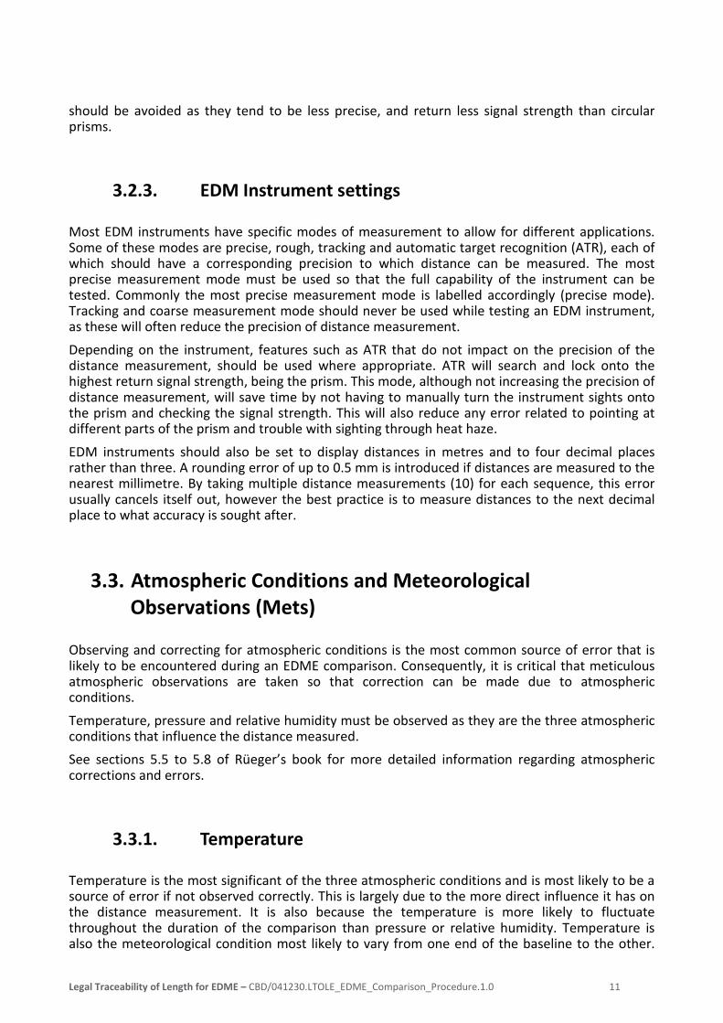
Refer to Appendix C for an extract of the booking sheets and an example of how they should be filled out. Numbers depicted in red relate to the observation sequence booking order described in the preceding section.
o AT station is the station that the EDM instrument is occupying. TO station is the station that the target (or prism) is occupying. AT / TO heights are likened to instrument / target heights respectively.
o Measure and record AT / TO heights from the top plate (pillared baselines) or permanent mark (ground mark baselines).
o Instrument and target heights may be rounded to the nearest 0.005m. Each station should have two heights (instrument and target) and depending on the instrument and prism combination, should not differ by more than 0.01m.
o Stations suspected of movement or damage should be observed unless stated otherwise under Baseline Status on the department’s webpage.
Legal Traceability of Length for EDME – CBD/041230.LTOLE_EDME_Comparison_Procedure.1.0 22

Checks and pack up 4.2.3.
Upon completion of the sequence observations, the following steps should be carried out:
1. Ensure booking sheets are complete and where possible, perform suitable rough checks for correctness. Each sequence should have the following data:
a. start time (and stop time if taking remote mets)
b. AT - TO station IDs and heights
c. mean temperature (from 3 instrument temperatures and multiple remote temperatures)
d. relative humidity
e. pressure
f. mean distance (from 10 measured distances).
2. Check all observation instruments (EDM and mets) to ensure that data has been successfully recorded and where possible, check that it is complete and correct. Once checked they should be turned off and placed into their designated storage containers.
3. Take down all remaining equipment (tribrachs, tripods, umbrellas etc.) and where appropriate, return any items to their specific storage containers.
a. Tribrachs should be checked (centred and level) prior to being taken down, especially if suspected of movement.
4. Ensure that wherever possible, the baseline is left in the same condition as it was upon arrival, taking all items and equipment, including rubbish.
5. Restore baseline security measures to original state. This may be removing pillar 5/8” bolts/threads, locking pillar plates/caps or locking gates.
a. Any specific access requirements should also be finalised prior to leaving (e.g. sign out, returning visitor pass/card and pillar bolts/keys).
It is important that any problems or errors that occurred during the EDME comparison are recorded immediately. These records should be made on the booking sheet with sufficient information so that corrections can be made at a later time as required.
Also note any problems or concerns relating to the baseline, and notify the relevant personnel as soon as possible.
This concludes the field procedures.
Legal Traceability of Length for EDME – CBD/041230.LTOLE_EDME_Comparison_Procedure.1.0 23

4.3. Office Procedures (Post-field)
The office procedures should be commenced as soon as possible once field observations have been completed. This section outlines the procedures for reducing the field observations to obtain a report on the performance of the instrument when compared to certified baseline values.
Firstly, the field observations must be checked against any electronic data recorded in the field. Bookings sheets must be complete including all mean calculations. Once the raw data has been checked, it can now be entered into the recommended processing software.
EDME Comparison Software 4.3.1.
The EDME comparison software that the department recommends has been produced by the Western Australian Land Information Authority (Landgate), and is called Baseline. This software package was selected as a part of a national approach to adopt a single software package across all jurisdictions. It is the view of the department that this software will be used for all EDME comparisons in Queensland. This software is designed to be a self-service style software package, where persons performing an EDME comparison will process the observations themselves using this software to obtain a report on the performance of the EDM instrument. This software is available from the department website.
4.3.1.1. Download Instructions:
To download and run the software: 1. Create the directory <C:\Program Files\Calibration\Baseline\>.
2. Download the compressed file (Distribution.zip) from the legal traceability page on the department’s website9 and place contents into the above directory.
3. Run the EDMCalibration.exe application.
a. If the error message “…HTML help is not installed on this computer…” occurs, download the relevant software update from the Microsoft Support website10. This will enable the help file to be viewed, however not through the baseline software. Open this file separately through windows explorer.
4.3.1.2. Software Instructions:
Instructions on how to use the software are contained within the inbuilt help file and should be referred to if experiencing difficulty or if unfamiliar with the software.
9 <http://www.nrm.qld.gov.au/property/surveying/legal-traceability/index.html> 10 <http://support.microsoft.com/kb/917607>
Legal Traceability of Length for EDME – CBD/041230.LTOLE_EDME_Comparison_Procedure.1.0 24

This software requires baseline values that are updated periodically by the department (after a baseline calibration). When this occurs, a new version of the software will be uploaded to the department’s website. It is recommended that user’s download the software periodically to ensure that the latest updates are received.
The software will also require specific instrument values in order to produce a comparison report. These values are commonly referred to as the first velocity correction or “C and D” values, and should be obtained from the relevant manufacturer for each instrument.
Software update instructions are the same as for the initial download. Before updating, it is important to backup all software files, particularly files located in the ‘database’ directory. These files contain past and current jobs along with baseline and instrument details that may be applicable when downloading new versions of the software. It may be worthwhile to keep a copy of the updated instrument file, so that the file is not overwritten when downloading new versions of the software. This will ensure that specific instruments and their values are not lost and thus required to be re-entered into the software.
4.3.1.3. Software Support:
The department is only able to offer limited assistance with this software. General enquiries may be sent to the local departmental contact or Regional Calibration Officer. Specific technical support may be sourced by contacting Landgate directly.
4.4. Comparison Reports
The final product of this procedure is to have a satisfactory report on the performance of an EDM instrument, produced by the recommended software. This report states the relationship between the measurements made by the instrument being tested and certified values from the baseline calibration performed by the Verifying Authority. The report does not necessarily indicate the current condition of the instrument. It only states how the instrument performed during the time it was tested.
Any report generated is valid for 1 year from the time of field testing. It is recommended that every instrument is tested on an EDM baseline once every year, and immediately after purchase or maintenance.
Instrument Correction Values 4.4.1.
This relationship is described as a single correction with two parts; Constant and Scale, and is expressed in the following way:
± ( χ + у x 10-3.L ) mm Where L is length in m
Alternatively, the more common expression is: ± ( χ mm + у PPM )
Applying this correction to measurements made by the instrument will ensure traceability to the national standard.
Legal Traceability of Length for EDME – CBD/041230.LTOLE_EDME_Comparison_Procedure.1.0 25

4.4.1.1. Assessment and Analysis of Results
The instrument correction should be checked to ensure that it reflects the quality of the instrument tested. As a general rule, this correction should approximate the precision to which the instrument is capable of measuring distances, as set by the manufacturer.
In the case where these corrections significantly exceed the manufacturer’s specifications, the following situation/s may have occurred and the appropriate action/s should be considered:
• EDME may not be in good working order. This will be unlikely if the instrument has been serviced prior to testing.
o Instrument may need to be serviced and then re-tested.
• Procedures not followed to a satisfactory standard. Commonly caused by poor mets observations and/or low precision instruments, and taking shortcuts to save time.
o Take greater care with all checks and field observations.
o Refer to section 3 and identify potential areas where uncertainties and errors can be reduced. Review section 4 and tweak procedure to include additional precautions where appropriate (e.g. use a pillared baseline instead of ground mark, and take remote mets).
o Review software output for outliers and eliminate suspicious observations. • Certified baseline values no longer accurate. Unlikely to occur if baseline has been recently
calibrated, however can occur if baseline monuments have been confirmed to be disturbed or have moved.
o Measurements to/from monuments that have moved or have been disturbed should be removed from the dataset processed in the software. If removing these observations improves the comparison result, the department should then be notified immediately so that a notice advising surveyors of the suspected disturbance can be posted on the department webpage under the Baseline Status heading.
4.5. Record Keeping
It is the responsibility of each individual company to maintain adequate historical records of all EDME comparisons performed for the instruments that the company owns and uses. Records should be kept indefinitely, as measurements made by any instrument and at any point in time, may be questioned.
At minimum, the following items should be kept for each EDME comparison, in both hardcopy and electronic form wherever possible:
• EDM and mets instrument service and maintenance records
• Raw data observations, either electronic data files or hardcopy booking sheets, for all physical measurements including distances and atmospheric conditions.
• reduction software input and output (including electronic data files, reports and certificates).
Legal Traceability of Length for EDME – CBD/041230.LTOLE_EDME_Comparison_Procedure.1.0 26

5. Definitions
Term Definition AS Australian Standard
Australian National Standard
The National Measurement Act 1960 and the National Measurement Regulations 1999 require that all Australian legal units of measurement of a physical quantity are to be made in terms of the SI unit of that physical quantity.
Australian Legal Units Under the National Measurement Regulation 1999, the Australian legal units are SI units.
ASIC Aviation Security Identification Card (ASIC). Information regarding the acquisition of an ASIC can be obtained from a regional airport, CASA or from the SCO.
Baseline Queensland utilises EDM Baselines as a means to calibrate and/or verify EDME. Traditionally, Queensland has adopted the Schwendener baseline design and usually consists of at least 7 stations set out at specific distances up to 1100m.
Calibration11 A set of operations that establish, under specific conditions, the relationship between values of quantities indicated by a measuring system, or values represented by a material measure or a reference material, and the corresponding value realised by standards.
CASA Civil Aviation Safety Authority (Australia).
Department The Department of Natural Resources and Mines (DNRM)
DNRM Department of Natural Resources and Mines
EDM Electronic Distance Measurement
EDME Electronic Distance Measuring Equipment or survey EDM instruments (total stations). For the purposes of this procedure document, the term ‘EDME’ does not include scanners, distance meters, GNSS equipment, or reflector-less mode on total stations.
Facility The laboratory defined under ISO/IEC 17025. For the purposes of NATA accreditation, the nominated facility within the Department is Cadastral and Geodetic Services.
Instrument operator The person who utilised the instrument to carry out the field observations required for processing. The instrument operator is also responsible for all activities performed on the day of field work.
IEC International Electro-Technical Commission
ISO International Standards Organisation
Legal Metrology Legal Metrology comprises all measurements carried out for any legal purpose and includes measurements that are subject to regulation by law or government decree.
Legal Traceability All measurements of physical quantities that are carried out for legal purposes or are subject to regulation by law or government decree are required to be made in terms of the legal SI units. The link between the physical measurements and the relevant SI unit is known as traceability. See Traceability.
LTOL Legal Traceability of Length
LTOLE Legal Traceability of Length for EDME
NATA National Association of Testing Authorities (Australia)
11 Definition acquired from the National Measurement Institute website <www.measurement.gov.au>
Legal Traceability of Length for EDME – CBD/041230.LTOLE_EDME_Comparison_Procedure.1.0 27

Term Definition NMI National Measurement Institute
PPM Parts Per Million. Can also be expressed as (x10-6)
RCO Regional Calibration Officer
Reference Standard of Measurement
See also State Primary Reference Standard
Regulation 13 Certificate A certificate issued by the SCO (NATA signatory) on behalf of the Director General of the Department in accordance with the requirements of Section 20 of the National Measurement Act (1960) and National Measurement Regulation (1999). Certification is valid for a period of two years provided that an EDM Baseline is calibrated to within the tolerance required for its prescribed use and that the baseline monumentation remains undisturbed. (See Error! Reference source not found.)
SCO The State EDM Calibration Officer (SCO) is an officer delegated by the Director General of the Department who is responsible for the management and calibration of EDM Baselines and verification of EDME. The SCO is required by the Department to be a NATA Authorised Signatory as per the NATA Rules 2006.
SI The SI (Standard International) unit for Length is the Metre (m).
Standardise12 To bring to or make of an established standard quantity or quality.
State Primary Reference Standard
The department verifies EDM baselines as a Reference Standard of Measurement under Regulation 13 of the National Measurement Regulations 1999, in accordance with the National Measurement Act 1960.
Traceability Traceability is the property of the result of a measurement or the value of a standard whereby it can be related to stated references, usually national or international standards through an unbroken chain of comparisons all having stated uncertainties.
VA Verifying Authority. In accordance with Regulation 73 of National Measurement Regulations 1999 (Cth), in force under the National Measurement Act 1960 (Cth), the Department is appointed a Verifying Authority for the verification and re-verification of the physical quantity length.
12 Definition acquired from Australian Macquarie dictionary
Legal Traceability of Length for EDME – CBD/041230.LTOLE_EDME_Comparison_Procedure.1.0 28

6. References
AS ISO/IEC 17025:2005 General Requirements for the Competence of Testing and Calibration Laboratories. National Association of Testing Authorities, Australia
Commonwealth of Australia, (1960). National Measurement Act.
Commonwealth of Australia, (1999). National Measurement Regulations.
DNRM, (1986). Calibration of Electronic Distance Measurement Baseline & Equipment. Department of Natural Resources and Mines, Queensland.
Queensland Government, (2003). Surveying and Mapping Infrastructure Act.
Queensland Government, (2004). Surveying and Mapping Infrastructure Regulation.
Rüeger, J.M. (1977). Design and Use of Baselines for the Calibration of EDM-Instruments. Proc., 20th Australian Survey Congress, Darwin, 175-189.
Rüeger, J.M. (1989). Electronic Distance Measurement: An Introduction – 3rd Totally Revised Edition. University of New South Wales.
Legal Traceability of Length for EDME – CBD/041230.LTOLE_EDME_Comparison_Procedure.1.0 29

Appendix A Regulation 13 EDM Baselines
Below is a list of the baselines which are periodically calibrated by the department.
1. Alice Springs (Morrie Hocking) *
2. Aloomba
3. Bundaberg
4. Caboolture
5. Cooktown
6. Darwin (High School) *
7. Gold Coast (Coombabah)
8. Goonyella
9. Howard Springs *
10. Mackay
11. Mareeba
12. Maroochy
13. Maryborough
14. Mica Creek (Mt Isa)
15. Toowoomba
16. Townsville
17. Tungamull (Rockhampton)
* Northern Territory baseline. Typically, the department is contracted to calibrate this baseline.
Legal Traceability of Length for EDME – CBD/041230.LTOLE_EDME_Comparison_Procedure.1.0 30

Appendix B Sequence Patterns
Forward Run Sequences Pattern Sequence Station (AT TO) 0 1 2 3 4 5 6 1 2 3 4 5 6 7 8 9 10 11 12 13 14 15 16 17 18 19 20 21 Reverse Run Sequences Pattern Sequence Station (AT TO)
0 1 2 3 4 5 6
1 2 3 4 5 6 7 8 9 10 11 12 13 14 15 16 17 18 19 20 21
Legal Traceability of Length for EDME – CBD/041230.LTOLE_EDME_Comparison_Procedure.1.0 31
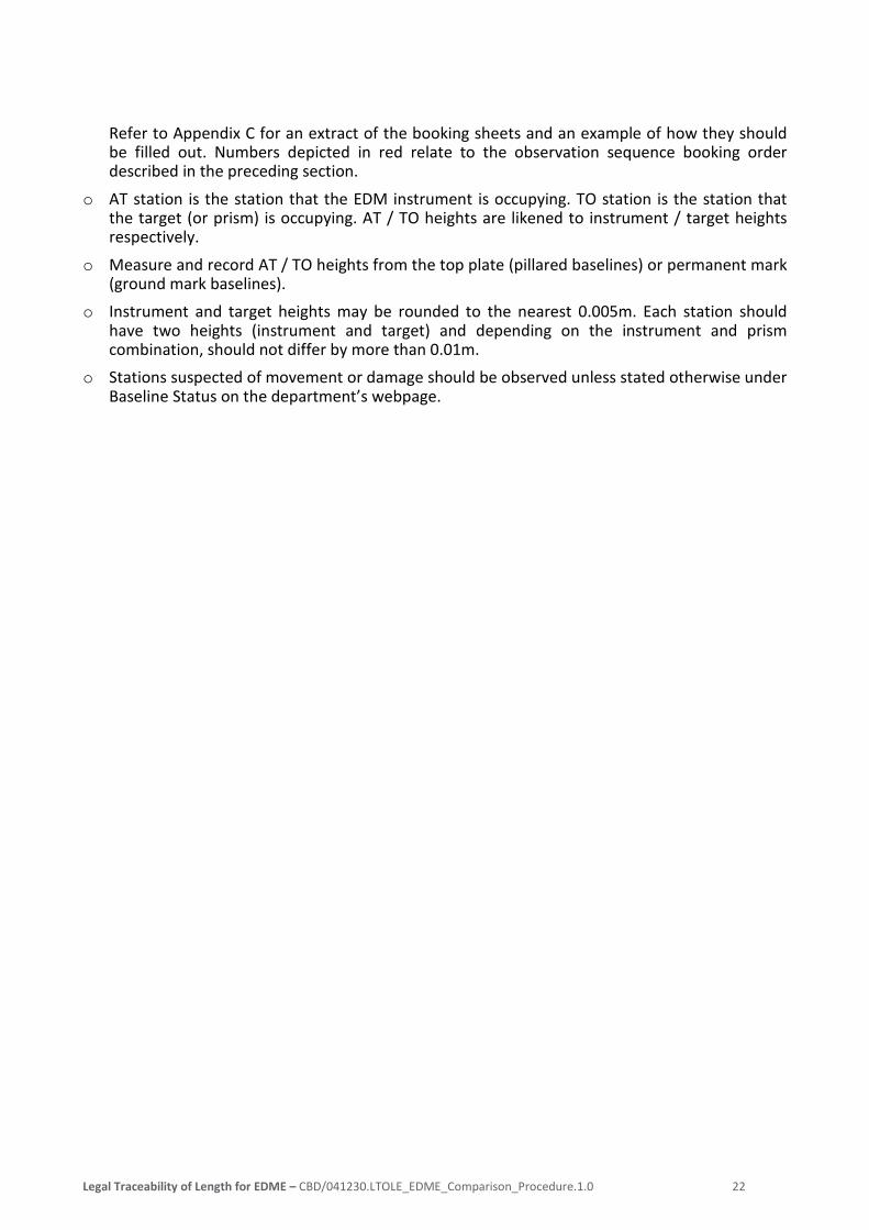
Appendix C Example Booking Sheet Extract
Below is an extract of the booking sheet, showing the fields that need to be filled in based on the procedure steps in section 4.2.2.2 (coloured red), and an example sequence dataset.
Mean temperature and distance may be calculated during the post-field stage if desired.
Legal Traceability of Length for EDME – CBD/041230.LTOLE_EDME_Comparison_Procedure.1.0 32