Embed Size (px)
Citation preview

رارررررررررررررررإ أنا المحع أدناه مقدم الرسال ال ي امل العنحان:
Resource Allocation in OFDM-Based Cognitive Two-Way Relay Networks نتاج جيدي الخاح، باستمناء ما تمت اإلشارة إليو حيمما ورد، ىو قر بأن ما اشتممت عميو ىذه الرسالة إنما ن ىذه الرسالة ككل و ي جزء منيا لم يقدم من قبل لنيل درجة و لقب عممي و بحمي لدى ي مؤسسة وا
تعميمية و بحمية خرى.DECLARATION
The work provided in this thesis, unless otherwise referenced, is the researcher's own work, and has not been submitted elsewhere for any other degree or qualification
:Student's name حمد محمد جندية اسم الطالب :Signature التوقيع :Date 3400 40 32 التاريخ
Resource Allocation in OFDM-Based
Cognitive Two-Way Relay Networks
Submitted by
Eng. Ahmed Jendeya
Supervised by
Dr. Ammar Abu Hudrouss Dr. Musbah Shaat
0241هـ - 4102م
A Thesis Submitted in Partial Fulfillment of Requirements for the Degree of Master in
Electrical Engineering-Communication Systems.
The Islamic University Gaza
Higher Education Deanship
Faculty of Engineering
Electrical Engineering
Communication Systems
غزة – اإلسالمية الجامعة
العليا الذراسات مادةع
الهنذسة كلية
الكهربائية الهنذسة
االتصاالت أنظمة

i
ABSTRACT
Cognitive radio (CR), nowadays, is considered as one of the most promising techniques
which introduce the flexible usage of radio spectrum and improve the spectral efficiency
by enabling unlicensed users to exploit the licensed spectrum in an opportunistic
manner. Moreover, the two-way relay communication has attracted a great attention as it
introduces a relaying scheme with a bidirectional transmission to exchange information
between two nodes. This strategy assumed to improve the overall capacity, since less
time slots are needed than the one-way strategy, besides extending the radio coverage
range of networks. Another common technique that improves the bandwidth efficiency
and spectrum utilization is the orthogonal frequency division multiplexing (OFDM)
technique which exhibits a distinctive efficiency in mitigating inter-symbol interference
(ISI) and combating frequency selective fading. Therefore, two-way relay CR
communication among OFDM terminals can take advantage of these three techniques to
boost up the capacity together with the networks quality.
In this thesis, an OFDM-based amplify and forward (AF), cognitive two-way
multiple-relay network is considered where two transceiver nodes exchange information
via relay nodes. The full transmission happens in two time slots. In the first time slot,
multiple access phase (MA), the transceiver nodes send their signals to the relay nodes
while in the second time slot, broadcast phase (BC), the relay nodes broadcast the
received signals to the transceivers.
In this dissertation, the problem to jointly optimize the network resources is
considered. The first is the transmission power of transceivers and relay nodes to ensure
suitable allocated power for best signals transmission besides ensuring no harmful
interference is caused to the primary system. The other important resource to be
optimized is the subcarrier pairing where the first and second time slots subcarriers have
to be matched such that the subcarriers with the best conditions is reserved. The final
tuned resource, in this work, is the relay selection where the relay node that assures the
best transition of the received signal is selected.
The dual decomposition technique is applied to get the optimal resource
allocation. Moreover, suboptimal algorithms are proposed to perform the resource
allocation reducing, significantly, the computational complexity compared with the
optimal solution with small performance degradation. Finally, simulation results of the
suggested AF OFDM cognitive relaying network are shown to compare the performance
gain of the different algorithms which reveals that the proposed suboptimal algorithm
achieves good performance with much less computational complexity than the optimal
one.

ii
الملخص
تعتبر أنظمة االتصاالت اإلدراكية في الوقت الراىن واحدة من أكثر التقنيات الواعدة ، والتي تتميز بخاصية استخدام بمن خالل تمكين مستخدمين غير مرخص ليم وذلك االستخدام المرن و الفعال لنطاقات التردد الشاغرة
عدم التسبب في حدوث تداخل ضار في موجات نتضم نطاق ترددي معين من استغاللو بطريقة انتيازيةمما يحسن كفاءة أنظمة االتصاالت خاصة في ظل التزايد المستمر لمتطبيقات الالسمكية المستخدمين المرخصين،
ومحدودية الترددات المتاحة.
ىذه كبير من قبل الباحثين نظرا ألن ىتمامابتحظى تجاىيناإلمن ناحية أخرى ، فإن االتصاالت ذات التقنية تقترح تبادل كامل لممعمومات بين طرفي اتصال خالل وحدتين من الزمن بدال من أربع وحدات المتبعة في
تجاه ، مما يضاعف كفاءة استغالل النطاق الترددي ويزيد من عدد مستخدمي الشبكةأنظمة االتصاالت أحادية اإل تحسين وتوسيع نطاق التغطية. مما يعمل عمى
لمنطاق الترددي أثبتت أىميتيا في زيادة نسبة االستغالل المتعامدإلى ما سبق ، فإن تقنية التقسيم إضافة والتداخل بين أكواد الترميز. األمثل لمنطاق الترددي المتاح ، إضافة ألىميتيا في مقاومة االضمحالل
استغالل النطاقات الترددية فإن بالنظر إلى التقنيات الثالث المذكورة ، وأىمية كل واحدة منيا في تحسين دارة موارد الشبكةب يسمحعممية دمجيم في شبكة اتصاالت واحدة تحقق أفضل بدرجة عالية التحكم في استخدام وا
ممكنة. ة استخدامعكفاءة وس
ق لمنطا المتعامدتقنية التقسيم تطبيقنتناول بالبحث شبكة اتصاالت السمكية مبنية عمى ، الرسالةفي ىذه القدرة اإلدراكية في شبكة اتصاالت ثنائية االتجاه ، حيث يعتمد االتصال فييا عمى يمع تقنية االتصال ذالترددي
كمرحل لمبيانات بحيث ،استغالل إحدى نقاط الشبكة المتوسطة مكانيا بين نقطتين ترغبان في تبادل المعموماتكان القدرة عمى االتصال مباشرة. في مثل ىذه الشبكة يتم ن ال تمميتتكفل بتوصيل المعمومات بين النقطتين المت
ل االتصال عمى مرحمتين: في الوحدة الزمنية األولى )مرحمة الوصول المتعدد( ترسل كل من النقطتين بياناتيا لممرح لممستخدمين إما اإلشارات المستممة وبثيا ودمج ل بدوره في الوحدة الزمنية الثانية )مرحمة البث( بجمعثم يقوم المرح
عادة إرساليا ، أو االكتفاء بتكبير اإلشارة فقط. بفك ترميز اإلشارات وا
القدرة الخاصة : لموارد الشبكة والتي أىمياه الدراسة ىو اإلدارة المتكاممة في ىذ التحدي األكثر أىمية لقدرة المناسبة لتوصيل استقبال أو مرحالت بحيث تضمن استخدام اأو بنقاط االتصال سواء كانت نقاط إرسالبين المزاوجةالمورد الثاني ىو إشارات المستخدمين المرخصين. معضار اإلشارة مع ضمان عدم حدوث تداخل
فضل. ذات الظروف األ قنوات االتصالتضمن استخدام لكيالموجات الحاممة الجزئية في كال مرحمتي االتصال

iii
لحل ىذه وذي يضمن أفضل انتقال لإلشارة بين طرفي االتصال. ل األمثل والالمورد األخير ىو اختيار المرح . بعد ذلكاألمثلل المزدوج والتي تضمن الحصول عمى حل ىو يتطبيق خوارزمية التحمباألطروحة تقومالمشكمة ي من األمثل لكنيا تتميز بأنيا أقل بكثير من ناحية التعقيد الحسابقريبة من الحل تعطي حموال خوارزميات اقترحت
تقنية التقسيم االتصاالت المقترحة المعتمدة عمى لشبكة محاكاةتم عرض نتائج أخيرا ل المزدوج. يالحل بطريقة التحملمتدليل عمى أداء التي تستخدم تقنية المرحالت القدرة اإلدراكية اتذ في بيئة االتصاالتلمنطاق الترددي المتعامد
الخوارزمية المقترحة القريبة من األمثل تعطي نتائج جيدة مع تميزىا بأنيا والتي أظيرت أن المختمفةالخوارزميات أقل بكثير من ناحية التعقيد الحسابي من الحل بطريقة التحميل المزدوج.

iv
All praise goes to Allah, the Creator and Lord of the Universe
and the Cause of Every Success in My Whole life
This Work is dedicated to …
My Great Parents,
My Dear Wife, and
Lovely Brothers and Kind Sister.

v
ACKNOWLEDGEMENTS
In the name of Allah the most Compassionate and the most Merciful who has
favored me with countless blessings.
It is really a great moment to reach this part of the thesis. When you are writing
the “acknowledgement” means that you are done, and you can take a deep breath and
look back through the days passed while you are stepping a stair up to remember and
thank all people who gave a significant push and made this step possible.
In fact, the major thanks and gratitude are owned to my supervisor, Dr. Musbah
Shaat, his advices, kind directions, guides and scientific assistant that draw and claried
the right way to reach this achievement were, always, the backbone alike.
I would like also to offer my heartfelt thanks to my co-supervisor, Dr. Ammar
Abu Hudrouss, who believed on me, provided me with support and always welcomed
my questions with the best possible guidance and hints.
A lot of thanks are to the Islamic University of Gaza library which facilitates the
accessibility to different important global libraries that made the research simpler and
efficient.
Great thanks to my parents for their nice prayers that blessed my life. Loving
thanks to my patient and kind wife Eslam who lived the pressure with me in the past two
years, my elder brother Mahmoud who was the best friend and gave me his heartfelt
advises and support, my warm-hearted and lovely sister Dr. Mayyada and my nice
younger brothers.
vi
TABLE OF CONTENTS
ABSTRACT ........................................................................................................................ i
ii ................................................................................................................................. الملخص
ACKNOWLEDGEMENTS ............................................................................................... v
LIST OF TABLES ............................................................................................................ ix
LIST OF FIGURES ........................................................................................................... x
LIST OF ABBREVIATIONS ........................................................................................... xi
CHAPTER 1
INTRODUCTION
1.1 Introduction .............................................................................................................. 1
1.2 Contributions ............................................................................................................ 2
1.3 Problem Definition and Motivation ......................................................................... 3
1.4 Objectives ................................................................................................................. 3
1.5 Literature Review ..................................................................................................... 4
1.6 Thesis Structure ........................................................................................................ 7
Bibliography ................................................................................................................... 8
CHAPTER TWO
COGNITIVE RADIO SYSTEMS
2.1 Introduction ............................................................................................................ 10
2.2 Cognitive Radio Network Characteristics .............................................................. 11
2.2.1 Cognitive Capability ........................................................................................ 12
2.2.2 Reconfigurability ............................................................................................. 12
2.3 Network Architecture and Applications ................................................................. 13
2.4 Cognitive Cycle ...................................................................................................... 14
2.4.1 Spectrum Sensing ............................................................................................ 14
2.4.2 Spectrum Decision ........................................................................................... 21
vii
2.4.3 Spectrum Sharing ............................................................................................ 21
2.4.4 Spectrum Mobility (Spectrum Handoff) ......................................................... 24
2.5 Applications ........................................................................................................... 25
2.5.1 Public Safety Networks ................................................................................... 25
2.5.2 Disaster Relief and Emergency Networks ....................................................... 25
Bibliography ................................................................................................................. 27
CHAPTER THREE
OFDM TECHNIQUE AND RELAYING NETWORKS
3.1 Introduction ............................................................................................................ 30
3.2 Orthogonal Frequency Division Multiplexing (OFDM) System ........................... 31
3.2.1 OFDM System Design and Benefits ............................................................... 31
3.2.2 Peak to- Average Power Ratio ........................................................................ 33
3.2.3 OFDM Applications ........................................................................................ 34
3.3 Relaying Networks ................................................................................................. 34
3.3.1 One-Way Relay Networks ............................................................................... 35
3.3.2 Two-Way Relay Networks .............................................................................. 37
Bibliography ................................................................................................................. 39
CHAPTER FOUR
RESOURCE ALLOCATION IN OFDM-BASED COGNITIVE TWO-WAY
MULTIPLE-RELAY NETWORKS
4.1 Introduction ............................................................................................................ 41
4.2 Constrained Optimization ...................................................................................... 41
4.2.1 Duality Theory ................................................................................................. 41
4.2.2 Time Sharing Condition .................................................................................. 43
4.2.3 Subgradient Method ........................................................................................ 43
4.3 OFDM-Based CR Two-way Relay System Model and Problem Formulation ...... 45
4.3.1 System Model .................................................................................................. 45
4.3.2 Problem Formulation ....................................................................................... 48
4.4 Optimal Resource Allocation Based On Dual Method .......................................... 49
4.4.1 Optimal Resource Allocation .......................................................................... 49
viii
4.4.2 Subgradient Method to Calculate the Optimal .......................................... 54
4.5 Suboptimal Algorithms .......................................................................................... 55
4.5.1 Proposed Suboptimal Greedy Algorithm (Proposed Suboptimal) .................. 55
4.5.2 Hungarian Pairing Suboptimal Algorithm (Suboptimal + Hungarian) ........... 56
4.5.3 Fixed Pairing Suboptimal (Suboptimal + Fixed)............................................. 57
4.6 Complexity Computations ..................................................................................... 57
4.7 Simulation Results ................................................................................................. 58
Bibliography ................................................................................................................. 62
CHAPTER FIVE
CONCLUSION AND FUTURE WORK
5.1 Conclusion.............................................................................................................. 63
5.2 Future Works .......................................................................................................... 64
Bibliography ................................................................................................................. 66
ix
LIST OF TABLES
Table 2.1: Comparison between the interference temperature, transmitter and primary
receiver detection schemes. ............................................................................................. 20
Table 4.1 Hungarian Algorithm. ...................................................................................... 53
Table 4.2 Proposed Suboptimal Algorithm. .................................................................... 56
Table 4.3 Computational complexity comparison ........................................................... 58
x
LIST OF FIGURES
Figure 2.1 Spectrum utilization. ...................................................................................... 11
Figure 2.2 Illustration of spectrum white space. .............................................................. 13
Figure 2.3 CR network architecture ................................................................................. 13
Figure 2.4 Cognitive Cycle .............................................................................................. 15
Figure 2.5 Spectrum sensing techniques .......................................................................... 15
Figure 2.6 Interference temperature model ...................................................................... 16
Figure 2.7 Matched filter technique ................................................................................. 17
Figure 2.8 Transmitter detection problems ...................................................................... 19
Figure 2.9 Spectrum sharing in CR networks .................................................................. 22
Figure 2.10 a) Spectrum overlay b) Spectrum underlay .................................................. 23
Figure 3.1 OFDM Transmitter ......................................................................................... 32
Figure 3.2 OFDM Receiver ............................................................................................. 33
Figure 3.3 One-way Relay Network ................................................................................ 36
Figure 3.4 Two-way relay network .................................................................................. 37
Figure 4.1 Two-way relaying OFDM cognitive radio network System model. .............. 45
Figure 4.2 Achieved capacity vs power constraint .......................................................... 59
Figure 4.3 Achieved capacity vs interference threshold .................................................. 60

xi
LIST OF ABBREVIATIONS
AF Amplify and Forward
BC Broadcast
BS Base Station
CP Cyclic Prefix
CR Cognitive Radio
CSI Channel State Information
DF Decode and Forward
FFT Fast Fourier Transformation
FCC Federal Communications Commission
IEEE Institute of Electrical and Electronics Engineers
ISI Inter-Symbol Interference
IFFT Inverse Fast Fourier Transformation
LO Local Oscillator
LTE Long Term Evolution
MA Multiple Access
MIMO Multiple Input Multiple Output
OFDM Orthogonal Frequency Division Multiplexing
OFDMA Orthogonal Frequency-Division Multiple Access
PAPR Peak-to-Average Power Ratio
PU Primary User
QoS Quality of Service
SU Secondary User
SNR Signal to Noise Ratio
WLAN Wireless Local Access Network
1
CHAPTER 1
INTRODUCTION
1.1 Introduction
In cognitive radio (CR) networks, a secondary, unlicensed, user (SU) coexists in
the same geographical area with a primary, licensed, user (PU) exploiting the holes in
the licensed spectrum band that is not occupied by any primary system node. The SUs
are allowed to communicate using these frequency slots as long as they do not cause
harmful interference to the PUs. This kind of communication exhibits an excellent
utilization of the frequency bands that boosts up the bandwidth efficiency and spectrum
utilization to much higher levels. The importance of CR technique rose to the surface
considering the spectrum bands as a natural resource that has to be effectively managed.
A great technique that supports and enhances the control features in CR networks
is the relaying process [5]-[9]. In relay networks, the direct link between the nodes that
need to exchange information may not exists due to worse channel conditions, large
distance, or the existence of obstacles. As a result, intermediate nodes act as relays by
receiving the node signals and transmitting them again such that they guarantee that each
node receives its desired signal. This technique assures better channel conditions and
less transmission power which means low level of interference caused to PUs, when
applied in CR systems, than the direct transmission case. Relay networks are, generally,
divided into two categories: one-way relaying and two-way relaying. In one-way relay
networks, the relay nodes receive information signal from a source node, in the first time
slot and then in the second time slot, it retransmits the received signal to a destination
node, using, in common, decode and forward (DF) or amplify and forward (AF)
schemes. Consequently, four time slots are needed if two nodes want to establish full
exchange of information since they cannot transmit in the same time. On the other hand,
2
in the two-way relay scheme, the relay nodes receive information signals from
transceivers in the first time slot, the multiple access phase (MA), and then in the second
time slot, the broadcast phase (BC), they broadcast the received signals to the
transceivers. This overcomes the one-way relay scheme and reveals the two-way
relaying benefits by doubling the spectral efficiency, since only two time slots are
needed to complete exchange of information between two nodes, besides increasing the
network capacity.
Furthermore, in this work the orthogonal frequency division multiplexing
(OFDM) technique is employed. This method increases the spectral efficiency by
transmitting information over multiple orthogonal narrowband subcarriers besides being
very effective in mitigating inter-symbol interference (ISI), combating frequency
selective fading.
1.2 Contributions
1. The three techniques, mentioned in section 1.1, CR, two-way relaying and
OFDM are combined to construct an OFDM-based AF CR two-way multiple-
relay network.
2. The main network resources that affect the system throughput the nodes
transmission power, subcarrier pairing between the two time slots, and the relay
assignment are studied
3. The network resources are managed and jointly optimized to achieve maximum
throughput while ensuring no harmful interference is introduced to the primary
system using:
1. Optimal solution based on the dual decomposition technique.
2. Suboptimal algorithms with much less computational complexity
compared to the optimal with small performance degradation.
3
1.3 Problem Definition and Motivation
In the recent years, the wireless communication systems have grown rapidly
which increase, consequently, the number of users on the expense of the limited
available bandwidth. So that, the optimal exploit of the network resources and
bandwidth is considered, nowadays, as one of the most important search and
development fields taking into account the best quality and performance. This vision has
led to the CR systems that are considered as a smart way of exploiting every single hole
in a spectrum of the primary network, in opportunistic manner, to be used in the
secondary network.
The main issue to be considered in the CR systems is to ensure that the SU does
not cause harmful interference to the PU by keeping the transmit power below a
threshold limit. Considering this main and important condition the researchers suggested
applying the CR idea in the relaying networks, where the communication between nodes
is held via intermediate relay nodes which decrease, significantly the required power
exploiting the spatial diversity. Moreover, deploying OFDM technique in the CR
relaying environment, [8] and [9], boost the effective usage of the PU spectrum to higher
percentage than single carrier system, where the frequency band is divided into
orthogonal narrow band subchannels.
Inspired by all of the above benefits, in this thesis, we propose an OFDM based
CR AF two-way multiple- relay network, where the network main resources, power,
subcarrier matching and relay assignment are jointly optimized to achieve the optimal
capacity while keeping the interference to PU below a prescribed limit.
1.4 Objectives
The main objectives for this study can be summarized in the following points:
1. To study the main theoretical background required in this thesis.
2. To model an OFDM based CR AF two-way multiple- relay network and describe
the system and the problem to be optimized by a set of efficient expressions and
equations.
4
3. To introduce an optimal solution based on the dual decomposition technique
where the dual variables are optimized using the subgradient method.
4. To propose suboptimal algorithm that has much less complexity than the optimal
with small performance degradation.
5. To launch a simulation process that shows the results obtained and compares the
performance of the optimal and suboptimal algorithms.
1.5 Literature Review
In this study, the problem of resource allocation in OFDM based CR AF network
is discussed. The resource allocation problem in relay networks has received much
attention over the past years. Vu and Kong in [1] considered a two-way relay OFDM
based DF system where they proposed an optimal subcarrier and power allocation
algorithm that match the subcarrier in order of channel power gain. The transmission in
their approach happens in three time slots. In the first and second time slots, the two
transceivers transmit their signals to the relay node then in the third time slot the relay
re-encode the received signals and broadcast them to the transceivers. The authors in [2]
introduced a joint resource allocation in two-way relay AF OFDM based multi-relay
network. They performed the allocation by solving the formulated problem using the
dual decomposition algorithm to obtain an asymptotically optimal solution. Moreover,
they proposed two suboptimal schemes to solve the problem with much less complexity
than the dual decomposition and small performance degradation. He et al. proposed, in
[3], a multi-subcarrier DF relay strategy, in two-way relay OFDM based network. Their
proposed technique does not need to perform subcarrier pairing process between the first
and second time slots transmission. Additionally, they introduced an optimal resource
allocation to characterize the achievable rate region of their proposed system by dividing
the main optimization problem into two first and second time slots subproblems then
solve them utilizing the advantages of ellipsoid method and the Lagrangian duality
optimization technique. The work in [4] considers a two-way relay OFDM based AF
system in which the authors developed an efficient technique for power allocating by
replacing the individual power constraints with the total power constraint where they
5
were able to obtain the closed form solution of the node powers, which is not a trivial
duty in individual power approach. Moreover, they proposed a two-step suboptimal
approach in which the power is optimally assigned to each subcarrier first, and then at
each subcarrier the assigned power is distributed to the three terminals. Their proposed
method was shown to assign 50% of the total power to relay irrespective of the channels.
The authors in [1], [2], [3] and [4] did not consider the CR technique that has
been applied in this thesis to serve the current researches in utilizing the spectrum bands.
Furthermore, the relaying transmission process in this dissertation occurs in only two
time slots, rather than three, which enhance the spectral efficiency by a very good
percent. Additionally, the scenario in this work depends on individual power constraints
approach since it is more general than the total power one, considered in [4]. The total
power constraint approach is more suitable when the different network nodes have the
same power source. Therefore, the individual power constraints approach is more
realistic.
CR two-way multi-relay AF network was considered in [5], in which the power
and relay selection are jointly optimized under individual power and primary system
interference constraints to achieve the maximum throughput. Moreover, they presented a
closed form solution of the optimal power allocation of the transceiver nodes, only,
while the relays power are fixed to be the minimum between the available power upper
bound and the interference threshold divided by the channel gain. In [6] the problem of
relay selection and resource allocation for two-way multi-relay CR network was
investigated assuming AF then DF schemes. They applied the dual decomposition
technique and subgradient method to find the optimal power allocation, where a closed
form solution is obtained in the same manner as [5]. Moreover, in [6], a suboptimal
approach based on the genetic algorithm was proposed.
The authors in [5] and [6] did not consider the multicarrier technique which
employed in this work in order to offer more flexibility in the resource distribution
process besides supporting, to a great extent, the fact that CR operates in noncontiguous
band.
6
The system in [7] presents an opportunistic spectrum sharing in two-way relay
OFDM based network in which the secondary system tries to help the primary system to
achieve its target rate when a low signal to noise ratio (SNR) is presented. The power
and subcarriers were jointly optimized such that the sum rate is maximized. Moreover,
their system considered a single relay with limited scenario where the secondary
network is a primary network helper not a separated network that can be utilized in a
different application rather than the primary system one. The work in this thesis is more
general and can be applied to networks that provide different services than the primary
network. In [8], Shaat and Bader studied the joint subcarrier matching and power
allocation in OFDM based one-way single relay CR system in order to maximize the
total system throughput under interference constraints that ensure no harmful
interference caused to the PUs. Additionally, they proposed an efficient suboptimal
scheme that has much less complexity than the asymptotically optimal one. The authors
followed the one-way relaying approach which is half the spectral efficiency of the two-
way relaying applied in this thesis. Additionally, they introduced a single relay model
which has been extended to a multiple-relay scenario in this study to generalize the
network and make the optimization process more flexible. In [9], the authors studied the
power allocation for OFDM based two-way single relay link in CR environment in order
to maximize the sum rate. They assumed individual power constraints for secondary
source and relay nodes while the interference assumed to be aggregated of the secondary
system. They solved the optimization problem using the dual decomposition method.
Their approach considered only the power allocation without optimizing the subcarrier
pairing. Moreover, they suggested a simple single relay model where no relay selection
process is needed. Saliya et al. in [10] discussed the optimal power allocation for
physical layer network coding two-way relay CR network where the sum rate is
maximized under total power constraint and interference power threshold. The authors
did not utilize the benefits of using the multicarrier technique. Moreover, they did not
perform optimization for other network resources rather than nodes power.
7
1.6 Thesis Structure
This dissertation is organized in five chapters; the first one, the introduction,
gives a smooth entrance to the topics studied throughout the rest chapters.
Chapter 2 describes the CR technique, shows its main contributions, common network
architecture, characteristics, advantages, drawbacks, and the current main applications of
this technique.
In Chapter 3, a brief background of the OFDM technique and the relaying networks is
presented.
Chapter 4 describes the system model, problem formulation, the optimal and
suboptimal algorithms that perform the resource allocation, and finally the simulation
results and discussion.
Chapter 5 comes to a conclusion that summarizes the important issues drawn out from
this study and the recommendations on future work to be carried on this subject.
A paper out of this thesis is submitted to IEEE International Workshop on
Cognitive Cellular Systems (CCS 2014), attached at the end of the thesis.
8
Bibliography
[1] Vu, H. N.; Kong, H-Y., "Joint subcarrier matching and power allocation in
OFDM two-way relay systems," Journal of Communications and Networks, vol.
14, no. 3, pp. 257-266, June 2012.
[2] Xiong, K.; Fan, P.; Letaief, K.B.; Yi S.; Lei, M., "Joint subcarrier-pairing and
resource allocation for two-way multi-relay OFDM networks," IEEE Global
Communications Conference (GLOBECOM), pp. 4874-4879, 3-7 Dec. 2012.
[3] He, F.; Sun, Y.; Xiao, L.; Chen, X.; Chi, C-Y.; Zhou, S., "Capacity region
bounds and resource allocation for two-way OFDM relay channels," IEEE
Transactions on Wireless Communications, vol. 12, no. 6, pp. 2904-2917, June
2013.
[4] Jang, Y-U.; Jeong, E-R.; Lee, Y. H., "A two-step approach to power allocation
for OFDM signals over two-way amplify-and-forward relay," IEEE Transactions
on Signal Processing, vol. 58, no. 4, pp. 2426-2430, April 2010.
[5] Ubaidulla, P.; Aissa, S., "Optimal relay selection and power allocation for
cognitive two-way relaying networks," IEEE Wireless Communications Letters,
vol. 1, no. 3, pp. 225-228, June 2012.
[6] Alsharoa, A.; Bader, F.; Alouini, M., "Relay selection and resource allocation for
two-way DF-AF cognitive radio networks," IEEE Wireless Communications
Letters, vol. 2, no. 4, pp. 427-430, August 2013.
[7] Lu, W. D.; Gong, Y.; Ting, S. H.; Wu, X. L.; Zhang, N-T., "Cooperative OFDM
relaying for opportunistic spectrum sharing: protocol design and resource
allocation," IEEE Transactions on Wireless Communications, vol. 11, no. 6, pp.
2126-2135, June 2012.
[8] Shaat, M.; Bader, F., "Joint subcarrier pairing and power allocation for DF-
relayed OFDM cognitive systems," IEEE Global Telecommunications
Conference (GLOBECOM 2011), pp. 1-6, 5-9 Dec. 2011.
[9] Li, Y.; Zhang, X.; Peng, M.; Wang, W., "Optimal power allocation for OFDM-
based two-way relaying in cognitive radio networks," IEEE Wireless

9
Communications and Networking Conference (WCNC), pp. 528-532, 7-10 April
2013.
[10] Jayasinghe, L.K.S.; Rajatheva, N.; Latva-aho, M., "Optimal Power Allocation
for PNC Relay Based Communications in Cognitive Radio," IEEE
International Conference on Communications (ICC), pp. 1-5, 5-9 June 2011.
10
CHAPTER TWO
COGNITIVE RADIO SYSTEMS
2.1 Introduction
As the demand of enormous data rates in the wireless communication systems
and applications grows rapidly, the requirement of efficient spectrum usage becomes an
insistent need considering the natural frequency spectrum limitations. Surveys from the
Federal Communications Commission (FCC) confirmed that 90 percent of the time,
many licensed frequency bands remained idle [1]. Moreover, a large portion of the
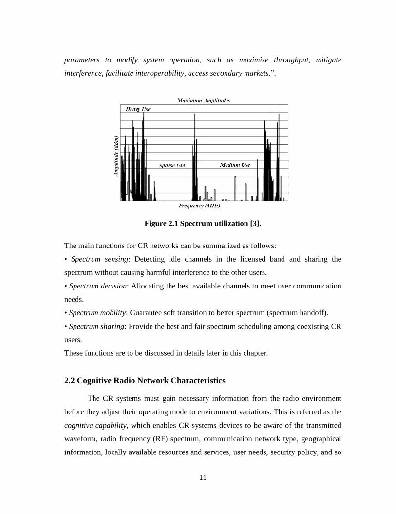
assigned spectrum is used intermittently as shown in Figure 2.1. Independent studies
held in some countries confirmed this surveys, and concluded that spectrum utilization
depends strongly on time and place. So that it becomes obvious that the current
conventional static frequency allocation schemes cannot meet the actual needs of the
increasing number of higher data rate devices, especially, considering that the recent
communication systems are no longer voice only systems, but also includes multimedia
applications.
As a result, CR networks have been proposed as a very useful and smart solution
to a great extent that has the ability to overcome these spectrum barriers. In CR
networks, SUs are permitted to use the same spectrum of the PUs in an opportunistic
manner by dynamically senses for frequency holes, frequency channels that are not
occupied by the PU, and then use the best available channel to establish their
communication.
The CR concept has many definitions in several contexts but in this study, we
use the definition adopted by Federal Communications Commission (FCC) [2]:
“Cognitive radio: A radio or system that senses its operational electromagnetic
environment and can dynamically and autonomously adjust its radio operating
11
parameters to modify system operation, such as maximize throughput, mitigate
interference, facilitate interoperability, access secondary markets.”.
Figure 2.1 Spectrum utilization [3].
The main functions for CR networks can be summarized as follows:
• Spectrum sensing: Detecting idle channels in the licensed band and sharing the
spectrum without causing harmful interference to the other users.
• Spectrum decision: Allocating the best available channels to meet user communication
needs.
• Spectrum mobility: Guarantee soft transition to better spectrum (spectrum handoff).
• Spectrum sharing: Provide the best and fair spectrum scheduling among coexisting CR
users.
These functions are to be discussed in details later in this chapter.
2.2 Cognitive Radio Network Characteristics
The CR systems must gain necessary information from the radio environment
before they adjust their operating mode to environment variations. This is referred as the
cognitive capability, which enables CR systems devices to be aware of the transmitted
waveform, radio frequency (RF) spectrum, communication network type, geographical
information, locally available resources and services, user needs, security policy, and so
12
on then the CR devices can dynamically change their transmission and operating
parameters according to the sensed environment variations and achieve optimal
performance, which is referred to as reconfigurability [4].
2.2.1 Cognitive Capability
Cognitive capability refers to the ability of the radio technology to capture or
sense the information from its radio environment. This capability cannot simply be
realized by monitoring the power in some frequency bands of interest but more
sophisticated techniques are required in order to capture the temporal and spatial
variations in the radio environment and avoid interference to other users. Through this
capability, the portions of the spectrum that are unused at a specific time or location can
be identified. Consequently, the best spectrum and appropriate operating parameters can
be selected [3].
The cognitive capability relies on the adaptive operation in open spectrum task,
referred as the cognitive cycle, which will be discussed later in this chapter.
2.2.2 Reconfigurability
Reconfigurability is the ability of tuning the operating and transmission
parameters, on the fly, without any need of modifications on the hardware components.
Reconfigurability provides the basis for the following features [5]:
a) Adaptation of the radio interface so as to accommodate variations in the
development of new interface standards.
b) Incorporation of new applications and services as they emerge.
c) Incorporation of updates in software technology.
d) Exploitation of flexible heterogeneous services provided by radio networks.
The most important challenge, in CR networks is to share the licensed spectrum without
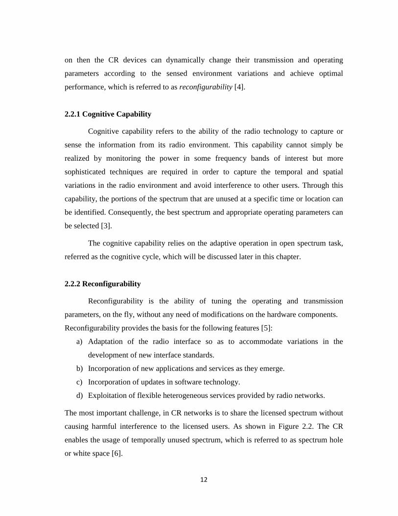
causing harmful interference to the licensed users. As shown in Figure 2.2. The CR
enables the usage of temporally unused spectrum, which is referred to as spectrum hole
or white space [6].
13
Figure 2.2 Illustration of spectrum white space [3].
2.3 Network Architecture and Applications
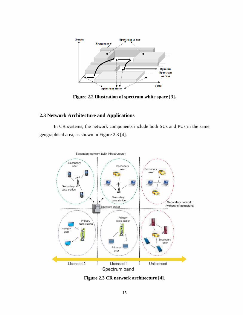
In CR systems, the network components include both SUs and PUs in the same
geographical area, as shown in Figure 2.3 [4].
Figure 2.3 CR network architecture [4].
14
A secondary network is a network that consists of a set of SUs with or without a
secondary base station (BS). SUs can only access the licensed spectrum when it is not
engaged by a PU while a primary network is consists of a set of PUs and one or more
primary BS. Primary network users have the right to use specific licensed spectrum
bands under the coordination of primary BS.
It should be noted that the PUs and the BSs are not, in common, equipped with
CR functions. As a result, the secondary network is required to detect, immediately, the
presence of a PU and transform the transmission to another available band so as to avoid
interfering with primary transmission. This will be discussed later in details the spectrum
mobility subsection. The spectrum broker is a central network component that has a
main role in sharing the spectrum resources among different CR networks. It can be
connected to every network and serve as a spectrum manager to enable coexistence of
multiple CR networks.
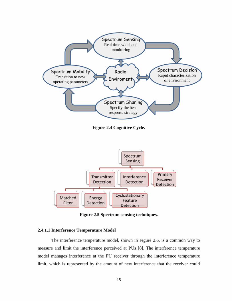
2.4 Cognitive Cycle
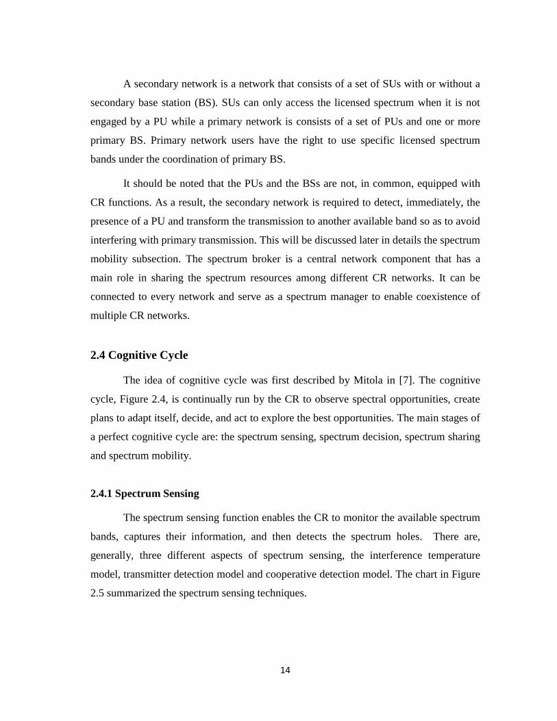
The idea of cognitive cycle was first described by Mitola in [7]. The cognitive
cycle, Figure 2.4, is continually run by the CR to observe spectral opportunities, create
plans to adapt itself, decide, and act to explore the best opportunities. The main stages of
a perfect cognitive cycle are: the spectrum sensing, spectrum decision, spectrum sharing
and spectrum mobility.
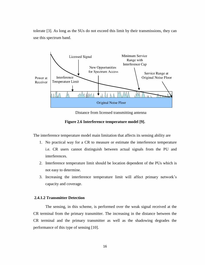
2.4.1 Spectrum Sensing
The spectrum sensing function enables the CR to monitor the available spectrum
bands, captures their information, and then detects the spectrum holes. There are,
generally, three different aspects of spectrum sensing, the interference temperature
model, transmitter detection model and cooperative detection model. The chart in Figure
2.5 summarized the spectrum sensing techniques.
15
Figure 2.4 Cognitive Cycle.
Figure 2.5 Spectrum sensing techniques.
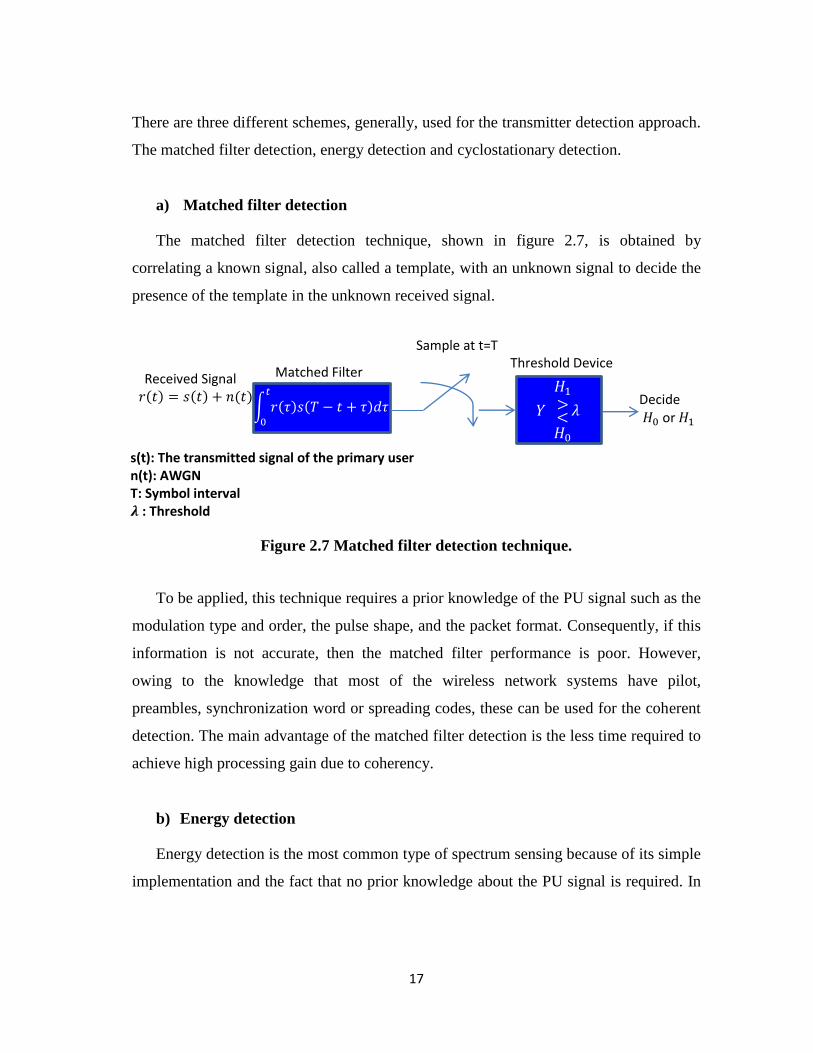
2.4.1.1 Interference Temperature Model
The interference temperature model, shown in Figure 2.6, is a common way to
measure and limit the interference perceived at PUs [8]. The interference temperature
model manages interference at the PU receiver through the interference temperature
limit, which is represented by the amount of new interference that the receiver could
Spectrum Sensing
Transmitter Detection
Matched Filter
Energy Detection
Cyclostationary Feature
Detection
Interference Detection
Primary Receiver
Detection
Spectrum Sharing Specify the best
response strategy
Spectrum Mobility Transition to new
operating parameters
Radio
Enviroment
Spectrum Decision Rapid characterization
of environment
Spectrum Sensing Real time wideband
monitoring
16
tolerate [3]. As long as the SUs do not exceed this limit by their transmissions, they can
use this spectrum band.
Figure 2.6 Interference temperature model [9].
The interference temperature model main limitation that affects its sensing ability are
1. No practical way for a CR to measure or estimate the interference temperature
i.e. CR users cannot distinguish between actual signals from the PU and
interferences.
2. Interference temperature limit should be location dependent of the PUs which is
not easy to determine.
3. Increasing the interference temperature limit will affect primary network’s
capacity and coverage.
2.4.1.2 Transmitter Detection
The sensing, in this scheme, is performed over the weak signal received at the
CR terminal from the primary transmitter. The increasing in the distance between the
CR terminal and the primary transmitter as well as the shadowing degrades the
performance of this type of sensing [10].
Distance from licensed transmitting antenna
17
There are three different schemes, generally, used for the transmitter detection approach.
The matched filter detection, energy detection and cyclostationary detection.
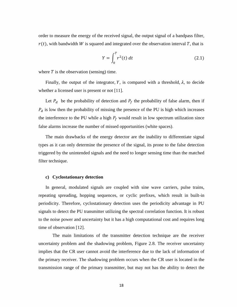
a) Matched filter detection
The matched filter detection technique, shown in figure 2.7, is obtained by
correlating a known signal, also called a template, with an unknown signal to decide the
presence of the template in the unknown received signal.
Figure 2.7 Matched filter detection technique.
To be applied, this technique requires a prior knowledge of the PU signal such as the
modulation type and order, the pulse shape, and the packet format. Consequently, if this
information is not accurate, then the matched filter performance is poor. However,
owing to the knowledge that most of the wireless network systems have pilot,
preambles, synchronization word or spreading codes, these can be used for the coherent
detection. The main advantage of the matched filter detection is the less time required to
achieve high processing gain due to coherency.
b) Energy detection
Energy detection is the most common type of spectrum sensing because of its simple
implementation and the fact that no prior knowledge about the PU signal is required. In
Decide 𝐻0 or 𝐻1
Threshold Device Sample at t=T
𝑟 𝑡 = 𝑠 𝑡 + 𝑛 𝑡 Received Signal
𝑟 𝜏 𝑠 𝑇 − 𝑡 + 𝜏 𝑑𝜏𝑡
0
𝑌 𝜆<𝐻0
𝐻1
>
Matched Filter
s(t): The transmitted signal of the primary user n(t): AWGN T: Symbol interval 𝝀 : Threshold
18
order to measure the energy of the received signal, the output signal of a bandpass filter,
, with bandwidth is squared and integrated over the observation interval , that is
= 2
0
where is the observation (sensing) time.
Finally, the output of the integrator, , is compared with a threshold, , to decide
whether a licensed user is present or not [11].
Let be the probability of detection and the probability of false alarm, then if
is low then the probability of missing the presence of the PU is high which increases
the interference to the PU while a high would result in low spectrum utilization since
false alarms increase the number of missed opportunities (white spaces).
The main drawbacks of the energy detector are the inability to differentiate signal
types as it can only determine the presence of the signal, its prone to the false detection
triggered by the unintended signals and the need to longer sensing time than the matched
filter technique.
c) Cyclostationary detection
In general, modulated signals are coupled with sine wave carriers, pulse trains,
repeating spreading, hopping sequences, or cyclic prefixes, which result in built-in
periodicity. Therefore, cyclostationary detection uses the periodicity advantage in PU
signals to detect the PU transmitter utilizing the spectral correlation function. It is robust
to the noise power and uncertainty but it has a high computational cost and requires long
time of observation [12].
The main limitations of the transmitter detection technique are the receiver
uncertainty problem and the shadowing problem, Figure 2.8. The receiver uncertainty
implies that the CR user cannot avoid the interference due to the lack of information of
the primary receiver. The shadowing problem occurs when the CR user is located in the
transmission range of the primary transmitter, but may not has the ability to detect the
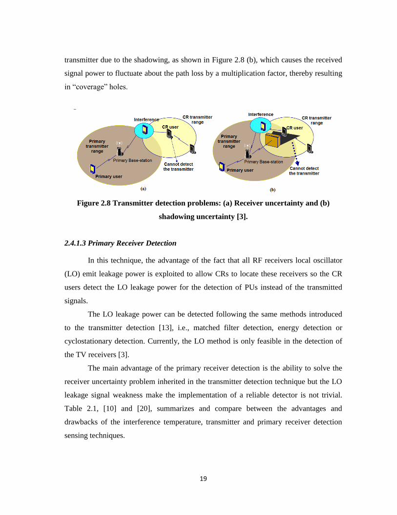
19
transmitter due to the shadowing, as shown in Figure 2.8 (b), which causes the received
signal power to fluctuate about the path loss by a multiplication factor, thereby resulting
in “coverage” holes.
Figure 2.8 Transmitter detection problems: (a) Receiver uncertainty and (b)
shadowing uncertainty [3].
2.4.1.3 Primary Receiver Detection
In this technique, the advantage of the fact that all RF receivers local oscillator
(LO) emit leakage power is exploited to allow CRs to locate these receivers so the CR
users detect the LO leakage power for the detection of PUs instead of the transmitted
signals.
The LO leakage power can be detected following the same methods introduced
to the transmitter detection [13], i.e., matched filter detection, energy detection or
cyclostationary detection. Currently, the LO method is only feasible in the detection of
the TV receivers [3].
The main advantage of the primary receiver detection is the ability to solve the
receiver uncertainty problem inherited in the transmitter detection technique but the LO
leakage signal weakness make the implementation of a reliable detector is not trivial.
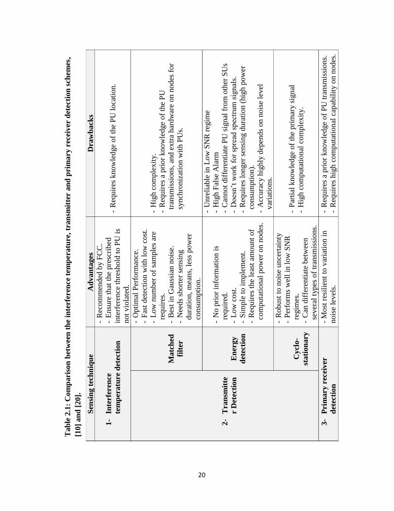
Table 2.1, [10] and [20], summarizes and compare between the advantages and
drawbacks of the interference temperature, transmitter and primary receiver detection
sensing techniques.
20
Sen
sin
g t
ech
niq
ue
Ad
van
tages
D
raw
back
s
1-
Inte
rfer
ence
tem
per
atu
re d
etec
tio
n
-R
ecom
men
ded
by F
CC
.
-E
nsu
re t
hat
the
pre
scri
bed
inte
rfer
ence
th
resh
old
to P
U i
s
not
vio
late
d.
-R
equir
es k
now
led
ge
of
the
PU
loca
tion
.
2-
Tra
nsm
itte
r D
etec
tion
Matc
hed
filt
er
- O
pti
mal
Per
form
ance
.
- F
ast
det
ecti
on w
ith l
ow
cost
.
- L
ow
num
ber
of
sam
ple
s ar
e
requir
es.
- B
est
in G
auss
ian n
ois
e.
- N
eeds
short
er s
ensi
ng
dura
tion, m
eans,
les
s po
wer
consu
mpti
on
.
- H
igh c
om
ple
xit
y.
- R
equir
es a
pri
or
kno
wle
dge
of
the
PU
tran
smis
sions,
and e
xtr
a har
dw
are
on n
odes
for
synch
roniz
atio
n w
ith P
Us.
En
ergy
det
ecti
on
- N
o p
rior
info
rmat
ion i
s
requir
ed.
- L
ow
cost
.
- S
imple
to i
mple
men
t.
- R
equir
es t
he
leas
t am
ou
nt
of
com
puta
tional
pow
er o
n n
odes
.
- U
nre
liab
le i
n L
ow
SN
R r
egim
e
- H
igh F
alse
Ala
rm
- C
annot
dif
fere
nti
ate
PU
sig
nal
fro
m o
ther
SU
s
- D
oes
n’t
work
fo
r sp
read
spec
trum
sig
nal
s.
- R
equir
es l
ong
er s
ensi
ng d
ura
tion (
hig
h p
ow
er
consu
mpti
on).
- A
ccura
cy h
ighly
dep
end
s on n
ois
e le
vel
var
iati
ons.
Cycl
o-
stati
on
ary
- R
obust
to n
ois
e unce
rtai
nty
- P
erfo
rms
wel
l in
low
SN
R
regim
es.
- C
an d
iffe
renti
ate
bet
wee
n
sever
al t
ypes
of
tran
smis
sions.
- P
arti
al k
now
ledge
of
the
pri
mar
y s
ign
al
- H
igh c
om
puta
tional
com
ple
xit
y.
3-
Pri
mary
rec
eiver
det
ecti
on
- M
ost
res
ilie
nt
to v
aria
tion i
n
nois
e le
vel
s.
- R
equir
es a
pri
or
kno
wle
dge
of
PU
tra
nsm
issi
on
s.
- R
equir
es h
igh c
om
puta
tional
cap
abil
ity o
n n
odes
.
Tab
le 2
.1:
Com
pari
son
bet
wee
n t
he
inte
rfer
ence
tem
pera
ture
, tr
an
smit
ter
an
d p
rim
ary
rec
eiv
er
det
ecti
on
sch
em
es,
[10]
an
d [
20].
21
2.4.2 Spectrum Decision
CR networks needs the capability to decide the best spectrum band among the
available sensed bands; this is what so called spectrum decision, which depends,
essentially, on the quality of service (QoS) requirements, spectrum characteristics and
the PU activity. Considering the QoS and spectrum characteristics, the CR system have
to be aware of data rate, acceptable error rate, delay bound, the transmission mode, and
the bandwidth of the transmission. Additionally, the CR users have to follow the PU
activity and take into account the number of spectrum handoffs, that happens in a certain
spectrum band to be considered in spectrum decision. Moreover, the spectrum decision
involves three main functions: spectrum characterization, spectrum selection and CR
reconfiguration.
Many parameters such as the channel interference level, error rate, path loss,
delay and holding time are important for efficient spectrum characterization. Once
spectrum holes are characterized, the next major step is to select the best available
spectrum suitable for the user’s specific QoS requirements. In CR networks, the set of
channels available for each node is not static due to dynamically changing topologies
and varying RF propagation characteristics. This implies that spectrum selection
techniques in CR networks should be closely coupled with routing protocols [15].
Based on spectrum characterization and spectrum selection, reconfiguration of
parameters occurs. The radio parameters that commonly reconfigured in CR networks
are modulation and coding scheme, transmission power, operating frequency, channel
bandwidth and communication technology.
2.4.3 Spectrum Sharing
The idea of the spectrum sharing in CR networks is similar to the medium access
control (MAC) principle in the existing classical systems. However, the case in CR
networks differs in the fact of the coexistence with the licensed system in the same
geographical area. The main three aspects of the spectrum sharing stage are the
22
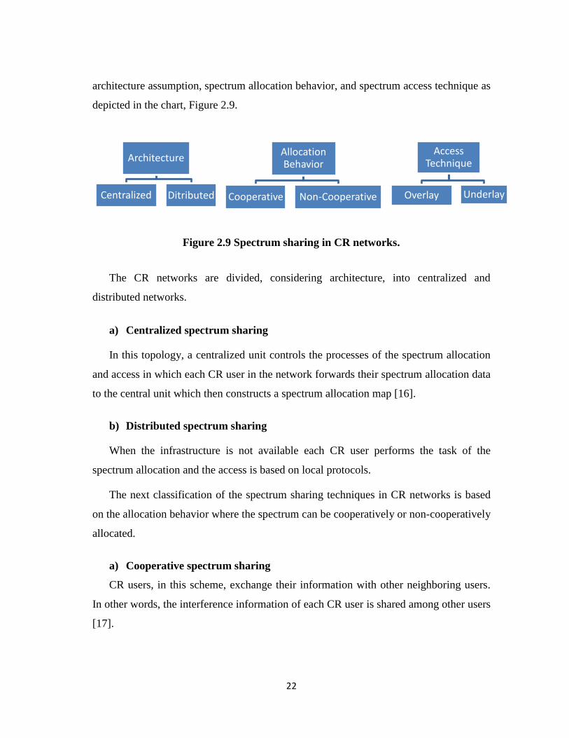
architecture assumption, spectrum allocation behavior, and spectrum access technique as
depicted in the chart, Figure 2.9.
The CR networks are divided, considering architecture, into centralized and
distributed networks.
a) Centralized spectrum sharing
In this topology, a centralized unit controls the processes of the spectrum allocation
and access in which each CR user in the network forwards their spectrum allocation data
to the central unit which then constructs a spectrum allocation map [16].
b) Distributed spectrum sharing
When the infrastructure is not available each CR user performs the task of the
spectrum allocation and the access is based on local protocols.
The next classification of the spectrum sharing techniques in CR networks is based
on the allocation behavior where the spectrum can be cooperatively or non-cooperatively
allocated.
a) Cooperative spectrum sharing
CR users, in this scheme, exchange their information with other neighboring users.
In other words, the interference information of each CR user is shared among other users
[17].
Architecture
Centralized Ditributed
Allocation Behavior
Cooperative Non-Cooperative
Access Technique
Overlay Underlay
Figure 2.9 Spectrum sharing in CR networks.
23
b) Non-cooperative spectrum sharing
Also referred as selfish spectrum sharing since it considers the node itself rather than
any other user’s parameters by selecting the channel with the objective of achieving
maximum throughput. The main disadvantage of the non-cooperative networks is that it
may result in reduced spectrum utilization.
The third, and final, classification of spectrum sharing in CR networks is based on
the access technology described as
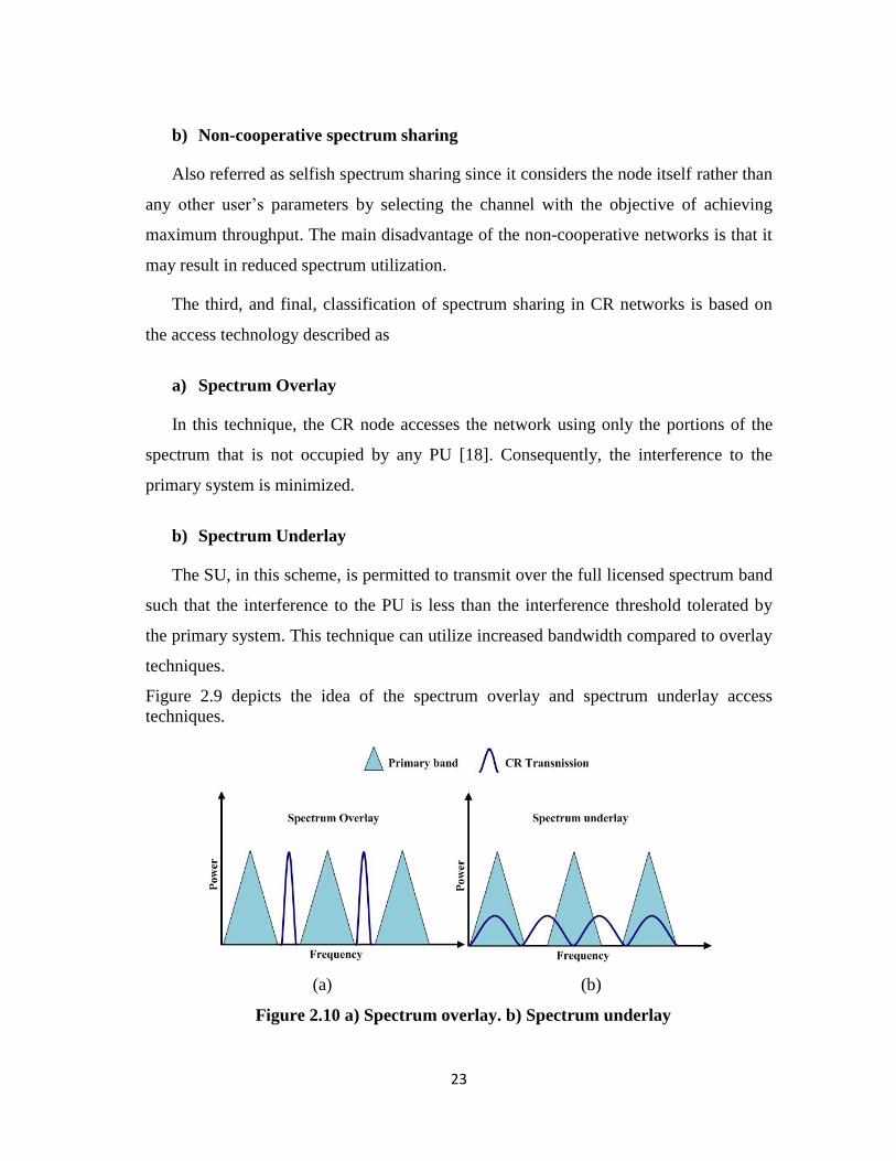
a) Spectrum Overlay
In this technique, the CR node accesses the network using only the portions of the
spectrum that is not occupied by any PU [18]. Consequently, the interference to the
primary system is minimized.
b) Spectrum Underlay
The SU, in this scheme, is permitted to transmit over the full licensed spectrum band
such that the interference to the PU is less than the interference threshold tolerated by
the primary system. This technique can utilize increased bandwidth compared to overlay
techniques.
Figure 2.9 depicts the idea of the spectrum overlay and spectrum underlay access
techniques.
(a) (b)
Figure 2.10 a) Spectrum overlay. b) Spectrum underlay
24
2.4.4 Spectrum Mobility (Spectrum Handoff)
In the classical cellular wireless networks, the handoff process occurs when the
signal power becomes weak. This usually happens at the cell boundary when the mobile
user moves from one cell to an adjacent one. In this case, the transition to a new suitable
base station becomes an insistent need in order not to drop the call. On the other hand, in
CR systems the handoff process, called spectrum handoff, takes place when a PU re-
appears in the licensed band or the channel conditions become worse in order to provide
the SU with smooth frequency transition with low latency. The transmission of the SUs
is suspended during a spectrum handoff; so that they will experience longer packet
delay.
A good way to alleviate the performance degradation due to long delay is to
reserve a certain number of channels for potential spectrum handoff [18].
The main steps of the spectrum handoff are
1- PU detection: Accomplished following one or more, if possible, of the
approaches described in spectrum sensing, subsection 2.4.1.
2- PU notification.
3- Channel switching: This depends, essentially, on the hardware switching
efficiency.
4- Resume communication: By one of the sharing techniques depicted in subsection
2.4.3.
The spectrum handoff could be classified into two main categories, reactive and
proactive handoff.
a) Reactive handoff: In this scheme, the CR user performs the handoff after
detecting the PU.
b) Proactive handoff: The handoff is performed when the CR user predicts that a
PU will access the current channel.
The main challenge in spectrum mobility techniques is to apply algorithms guarantee
that no severe performance degradation is caused to the applications during the handoff
process.
25
2.5 Applications
The ability of real-time decisions in networks decreases the burdens of
centralized spectrum management. Therefore, CR networking can be used in different
applications. It can provide military with adaptive, seamless, and secure
communications. Moreover, a CR network can also be implemented to enhance public
safety and homeland security. A natural disaster or terrorist attack can destroy existing
communication infrastructure, so an emergency network becomes indispensable to aid
the search and rescue [4]. Another important and promising application is the sensor
networks such as home monitoring, factory automation and disaster relief operations.
2.5.1 Public Safety Networks
Public safety networks are one of the applications that can exploit CR technique.
Police officers and fire and paramedic personnel use such networks for communication
among them. The public safety personnel do not have the technology to dynamically
operate across the different spectrum segments. Recall that public safety licensees have a
wide variety of bands available (VHF-Low, VHF-Hi, UHF below 800, UHF-800, etc.)
[21]. The CR technique can offer public safety networks more bandwidth through
opportunistic spectrum access. Moreover, a public safety CR network can provide a
substantial communication improvement by allowing the interoperetability across
different public safety services while adapting, smartly, to the high peak-to-average
nature of the traffic carried out by such networks.
2.5.2 Disaster Relief and Emergency Networks
The communications infrastructure, usually, collapsed as a result of natural
disasters such as hurricanes, earthquakes, wild fires, or other unpredictable phenomena.
This results in partially or fully damaged networks. Therefore, there is an urgent need
for a means of communications to facilitate the rescue team’s duty to be well organized
help. The CR networks can be used for such emergency networks [22].

26
The use of CR technique in disaster relief networks can provide a significant
amount of bandwidth that can deal with the expected huge amount of voice and
multimedia traffic e.g. transmitting videos locate a specific position of a survivor. It is
worth to mention the contribution of using wireless local access network (WLANs) in
the relief of the Haiti earthquake. However, the communication over such a network was
unreliable and suffered significant delays [23].
27
Bibliography
[1] S.P.T. Force, “Spectrum policy task force report,” Federal Communications
Commission ET Docket 02, vol. 135, 2002.
[2] “Notice of proposed rule-making and order: Facilitating opportunities for
flexible, efficient, and reliable spectrum use employing cognitive radio
technologies,” Federal Communications Commission ET Docket , No. 03-108,
Feb. 2005.
[3] Akyildiz, I. F. Lee, W-Y. Vuran, M. C.; Mohant, S. “Next generation/ dynamic
spectrum access/cognitive radio wireless networks: A survey,” Computer
Networks Journal (Elsevier), vol. 50, no. 13, pp. 2127–2159, September 2006.
[4] Wang, B.; Liu, K. J. R., "Advances in cognitive radio networks: A survey," IEEE
Journal of Selected Topics in Signal Processing, vol. 5, no. 1, pp. 5-23, Feb.
2011.
[5] Dillinger, M.; Madani, K.; Alonistioti, N., “Software defined radio:
Architectures, systems and functions,” John Wiley & Sons, 2005.
[6] Haykin; Simon, "Cognitive radio: brain-empowered wireless communications,"
IEEE Journal on Selected Areas in Communications, vol. 23, no. 2, pp. 201-220,
Feb. 2005.
[7] Mitola, J.; Maguire, G. Q., Jr., "Cognitive radio: making software radios more
personal," IEEE Personal Communications, vol. 6, no. 4, pp. 13-18, Aug 1999.
[8] “Establishment of interference temperature metric to quantify and manage
interference and to expand available unlicensed operation in certain fixed mobile
and satellite frequency bands,” Federal Communications Commission ET
Docket, 03-289, Notice of Inquiry and Proposed Rulemaking, 2003.
[9] “Notice of inquiry and notice of proposed Rulemaking”, Federal
Communications Commission ET Docket, No. 03-237, November 2003.
[10] Shaat, M.; “Resource Management in Multicarrier Based Cognitive Radio
Systems,” PhD’s thesis, Universitat Polit`ecnica de Catalunya (UPC), Spain,
2012.
28
[11] Digham, F. F.; Alouini, M-S.; Simon; Marvin K., "On the energy detection of
unknown signals over fading channels," IEEE International Conference
on Communications, 2003. ICC '03, vol. 5, pp.3575-3579 vol. 5, 11-15 May 2003.
[12] Du, K-L; Mow, W-H., "Affordable cyclostationarity-based spectrum Sensing for
cognitive radio with smart antennas," IEEE Transactions on Vehicular
Technology, vol. 59, no. 4, pp. 1877-1886, May 2010.
[13] Wild, B.; Ramchandran, K., "Detecting primary receivers for cognitive radio
applications," First IEEE International Symposium on New Frontiers in Dynamic
Spectrum Access Networks, DySPAN 2005, pp. 124-130, 8-11 Nov. 2005.
[14] Krishnamurthy, S.; Thoppian, M.; Venkatesan, S.; Prakash, R., "Control channel
based MAC-layer configuration, routing and situation awareness for cognitive
radio networks," IEEE Military Communications Conference, 2005. MILCOM
2005, pp. 455-460 Vol. 1, 17-20 Oct. 2005.
[15] Masonta, M. T.; Mzyece, M.; Ntlatlapa, N., "Spectrum Decision in Cognitive
Radio Networks: A Survey," IEEE Communications Surveys & Tutorials, vol. 15,
no. 3, pp. 1088-1107, Third Quarter 2013.
[16] Seyed, Z. A.; Li, X., "User-central wireless system: ultimate dynamic channel
allocation," IEEE International Symposium on New Frontiers in Dynamic
Spectrum Access Networks, 2005. DySPAN 2005, pp. 82-87, 8-11 Nov. 2005.
[17] Ma, L.; Han, X.; Shen, C-C., "Dynamic open spectrum sharing MAC protocol
for wireless ad hoc networks," IEEE International Symposium on New Frontiers
in Dynamic Spectrum Access Networks, 2005. DySPAN 2005, pp. 203-213, 8-11
Nov. 2005.
[18] Papadimitratos, P.; Sankaranarayanan, S.; Mishra, A., "A bandwidth sharing
approach to improve licensed spectrum utilization," IEEE Communications
Magazine, vol. 43, no. 12, pp. supl. 10, supl. 14, Dec. 2005.
[19] Li, C.; Li, C., "Opportunistic spectrum access in cognitive radio networks," IEEE
International Joint Conference on Neural Networks(IEEE World Congress on
Computational Intelligence). IJCNN 2008, pp. 3412-3415, 1-8 June 2008.
29
[20] Akan, O. B.; Karli, O.; Ergul, O., "Cognitive radio sensor networks," IEEE
Network, vol. 23, no. 4, pp. 34-40, July-August 2009.
[21] Gorcin, A.; Arslan, H., “Public safety and emergency case communications:
Opportunities from the aspect of cognitive radio,” IEEE DySPAN, Chicago, IL
2008.
[22] Rehmani, M. H.; Viana, A. C.; Khalife, H.; Fdida, S., “A cognitive radio based
internet access framework for disaster response network deployment. Research
Report” http://hal.inria.fr/inria-00482593/en/ (2010). Accessed 25 July 2012.
[23] Goldstein, H., “Engineers help NGOs get online after Haiti quake” IEEE
Spectrum, 2010.
30
CHAPTER THREE
OFDM TECHNIQUE AND RELAYING NETWORKS
3.1 Introduction
CR networks require efficient physical layer. Therefore, the OFDM technique,
known to be suitable for the physical architecture, has been recommended for the CR
systems because of its capability to perform underlying sensing besides the ability to
occupy the empty gaps left by the primary system users. The OFDM flexibility provides
opportunities to be used in advanced systems such as CR networks.
OFDM divides the target spectrum into orthogonal narrowband subchannels
where the signal values are modulated on the subchannels in frequency domain.
Interference to the PUs is avoided by simply nullifying the subchannels in the occupied
spectrum segments and modulating only the subchannels in the unused spectrum
segments. With a sufficient number of subchannels, an OFDM-based CR system can
operate efficiently in any target PU spectrum regardless of its channelization scheme [1].
Employing OFDM technique in the CR environment decreases the overall
sensing time since if a PU appears at a single carrier, sensing in other carriers is not
necessary. Furthermore, OFDM based CR networks have the ability to use multiple
spectrum bands, simultaneously, for the transmission.
Another factor that, significantly, increases the OFDM based CR network
efficiency when coupled with the cooperative networks principal. Cooperative
communications emerged to exploit the spatial diversity gains inherited in the multiuser
wireless systems without the need of multiple antennas at each node. This is achieved by
having the users relay each other’s messages and thus forming multiple transmission
paths to the destination [2].
31
The relay-assisted wireless networks ensure better channel conditions, increase
coverage and less transmission power than the direct link transmission case which
means low level of interference is caused to PUs.
In this study, the CR principal is deployed in an OFDM based two-way multiple-
relay network.
3.2 Orthogonal Frequency Division Multiplexing (OFDM) System
3.2.1 OFDM System Design and Benefits
The concept of OFDM dates back to 1960s. In OFDM, the entire band is divided
into many narrowband orthogonal subchannels, which are transmitted in parallel to
maintain high data rate transmission and, at the same time, increase the symbol duration
to combat ISI, a form of distortion of a signal in which one symbol interferes with
subsequent symbols because of multipath fading, [3]-[6]. Additionally, orthogonal
subcarriers offer the ability to be decoded separately.
The basic idea of OFDM modulation is to divide the transmitted bitstream into
many different substreams and send these over many different subchannels. Typically
the subchannels are orthogonal under ideal propagation conditions. The orthogonality
requires that the sub-carrier spacing is =
Hertz, where is the symbol duration,
and is a positive integer, typically equal to 1. Moreover, the data rate on each of the
subchannels is much less than the total data rate, and the corresponding subchannel
bandwidth is much less than the total system bandwidth [7].
The duration of the OFDM symbol is longer than the single carrier modulation
and its bandwidth is narrower. Consequently, the OFDM systems are more robust to
frequency-selective fading, in which different frequency components of the signal
experience uncorrelated fading, by driving each subcarrier to be exposed to flat fading
rather than frequency selective fading. On the other hand, OFDM is more sensitive to
the time-varying impairment of channels.
32
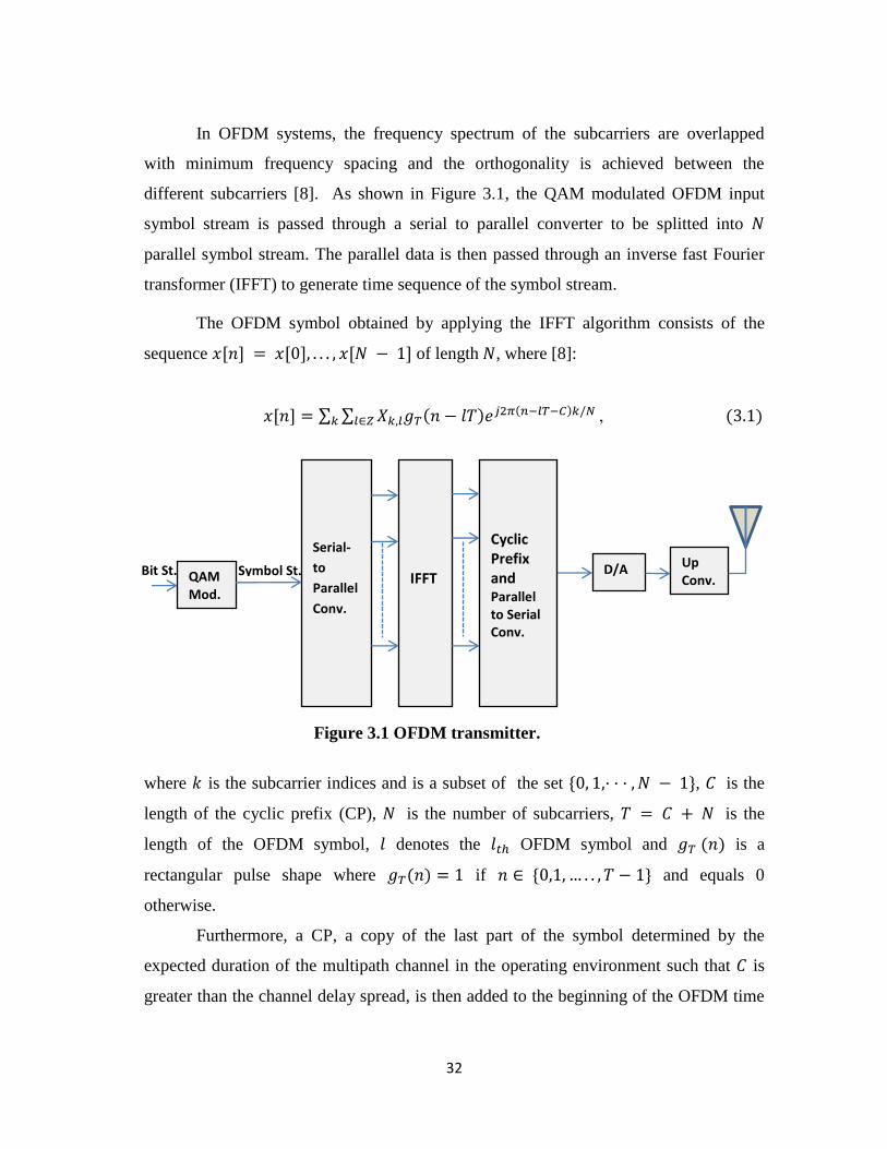
In OFDM systems, the frequency spectrum of the subcarriers are overlapped
with minimum frequency spacing and the orthogonality is achieved between the
different subcarriers [8]. As shown in Figure 3.1, the QAM modulated OFDM input
symbol stream is passed through a serial to parallel converter to be splitted into
parallel symbol stream. The parallel data is then passed through an inverse fast Fourier
transformer (IFFT) to generate time sequence of the symbol stream.
The OFDM symbol obtained by applying the IFFT algorithm consists of the
sequence = − of length , where [8]:
= ∑ ∑ − 2 ,
Figure 3.1 OFDM transmitter.
where is the subcarrier indices and is a subset of the set − , is the
length of the cyclic prefix (CP), is the number of subcarriers, = + is the
length of the OFDM symbol, denotes the OFDM symbol and is a
rectangular pulse shape where = if − and equals 0
otherwise.
Furthermore, a CP, a copy of the last part of the symbol determined by the
expected duration of the multipath channel in the operating environment such that is
greater than the channel delay spread, is then added to the beginning of the OFDM time
D/A
Serial-
to
Parallel
Conv.
IFFT
Cyclic Prefix and Parallel to Serial Conv.
Symbol St. QAM Mod.
Bit St. Up Conv.
33
sequence which acts as guard interval to combat ISI from the previous symbol. The
cyclic prefix serves to eliminate ISI between the data blocks, because the first samples
of the channel output affected by this ISI can be discarded without any loss relative to
the original information sequence. Moreover, it allows the linear convolution of a
frequency-selective multipath channel to be modeled as circular convolution [7]. The
resulting digital signal is ordered by a parallel to serial converter then turned into an
analog signal, through digital to analog converter, upconverted and finally passed to the
antenna to be transmitted through the channel.
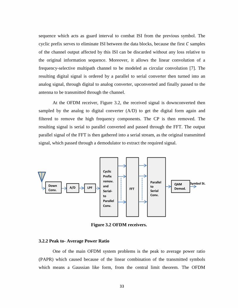
At the OFDM receiver, Figure 3.2, the received signal is downconverted then
sampled by the analog to digital converter (A/D) to get the digital form again and
filtered to remove the high frequency components. The CP is then removed. The
resulting signal is serial to parallel converted and passed through the FFT. The output
parallel signal of the FFT is then gathered into a serial stream, as the original transmitted
signal, which passed through a demodulator to extract the required signal.
3.2.2 Peak to- Average Power Ratio
One of the main OFDM system problems is the peak to average power ratio
(PAPR) which caused because of the linear combination of the transmitted symbols
which means a Gaussian like form, from the central limit theorem. The OFDM
Figure 3.2 OFDM receivers.
A/D
Cyclic
Prefix
remov.
and
Serial-
to
Parallel
Conv.
FFT
Parallel to Serial Conv.
QAM Demod.
Symbol St. LPF
Down Conv.
34
transmitted signal has a very large PAPR compared with the single carrier modulation.
The PAPR problem may cause nonlinear distortion of the amplifier at the transmitter.
Many approaches have been proposed to reduce the PAPR of OFDM signals.
Back off the operating points of nonlinear power amplifiers is a classical method of
reducing the large PAPR. However, this method severely reduces the efficiency of the
power amplifiers. Clipping and filtering, [9], selected mapping (SLM), [10], and partial
transmit sequence (PTS) are also another methods that reduce the PAPR problem. The
clipper method could be, directly, used to reduce the PAPR of an OFDM signal but it
may cause in-band distortion and out-of-band radiation due to nonlinearity [11].
The SLM and PTS techniques are distortionless compared with the clipping and filtering
techniques but they are with heavy computational complexity.
3.2.3 OFDM Applications
OFDM has been applied in several wireless communication applications,
because of its efficient features, such as terrestrial digital video broadcasting and
European digital audio broadcasting. Moreover, OFDM has been exploited in many
IEEE standards, e.g. IEEE 802.11a/g/n, IEEE 802.15.3a, and IEEE 802.16d/e.
Furthermore, the orthogonal frequency division multiple access (OFDMA), achieved by
allocating a group of subcarriers to a specific user, is considered, currently, as one of the
most promising radio transmission techniques for long term evolution (LTE) wireless
communication systems.
In this thesis, we apply the OFDM technique in a CR two-way multiple-relay
network which supports the underlying sensing that decrease the overall sensing time of
the system. The OFDM can be used to construct the transceiver of CR networks by
virtue of its flexibility for subchannel assignment and power allocation [12].
3.3 Relaying Networks
Relay communication systems are important, in general, when reliable
communication cannot be guaranteed by using a conventional direct link
35
communication. The spatial diversity of relay networks and space-time codes, both, can
be used to improve the transmitted signal quality, thereby enhancing the channel
capacity. Moreover, the relay communications are a promising technique that combat
signal fading due to multipath radio propagation. It also improves the system
performance and coverage area.
The concept of relaying has also been integrated into major specifications for
next generation wireless communications such as the IEEE 802.16j [18]. The relay
networks are divided, generally, into two categories: one-way and two-way relay
networks, which will be discussed in sections 3.3.1 and 3.3.2, respectively. In the relay
networks, the relay node retransmits the signal received following two basic schemes,
[13]-[16], AF and DF. In the AF scheme, the relay received a signal in the first time slot
and then retransmits an amplified version of the received signal in the second time slot.
The main advantage of this technique is the simple implementation and significant
efficiency in high signal to noise ratio (SNR) regimes. On the other hand, the main
drawback is the amplification of the noise signal which degrades the performance in low
SNR regimes. In DF the relay decodes the received signal, in the first time slot, before
transmitting a fresh version of the signal in the second time slot. The DF technique is
efficient in low SNR regimes.
3.3.1 One-Way Relay Networks
Consider the three-node relay system shown in Figure 3.3. Let be the source
node that intends to transmit a message to the destination node while is an
intermediate node serves as relay node. There is no direct link between and due to
poor channel conditions. Consequently, the relay assists the source to destination
transmission in order to increase the system coverage and achievable capacity.
In the first time slot, transmits its signal to . The received signals at the relay
node, , can be expressed as [17]:
= √ + ,
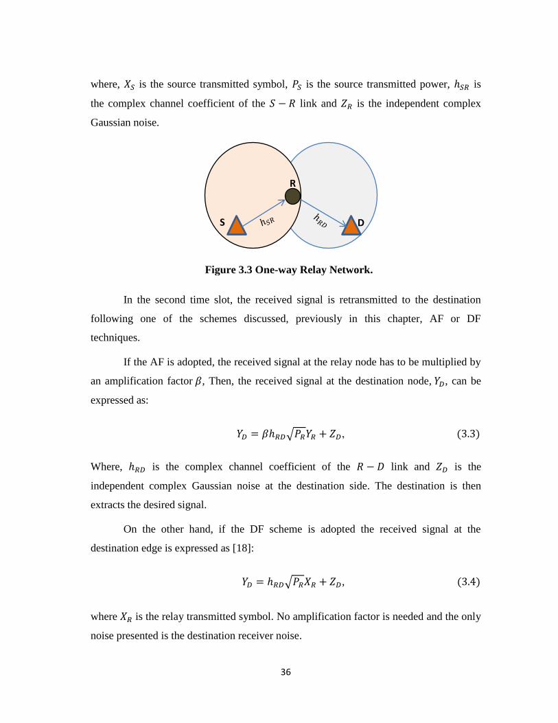
36
where, is the source transmitted symbol, is the source transmitted power, is
the complex channel coefficient of the − link and is the independent complex
Gaussian noise.
In the second time slot, the received signal is retransmitted to the destination
following one of the schemes discussed, previously in this chapter, AF or DF
techniques.
If the AF is adopted, the received signal at the relay node has to be multiplied by
an amplification factor , Then, the received signal at the destination node, , can be
expressed as:
= √ + ,
Where, is the complex channel coefficient of the − link and is the
independent complex Gaussian noise at the destination side. The destination is then
extracts the desired signal.
On the other hand, if the DF scheme is adopted the received signal at the
destination edge is expressed as [18]:
= √ + ,
where is the relay transmitted symbol. No amplification factor is needed and the only
noise presented is the destination receiver noise.
R
S D
Figure 3.3 One-way Relay Network.
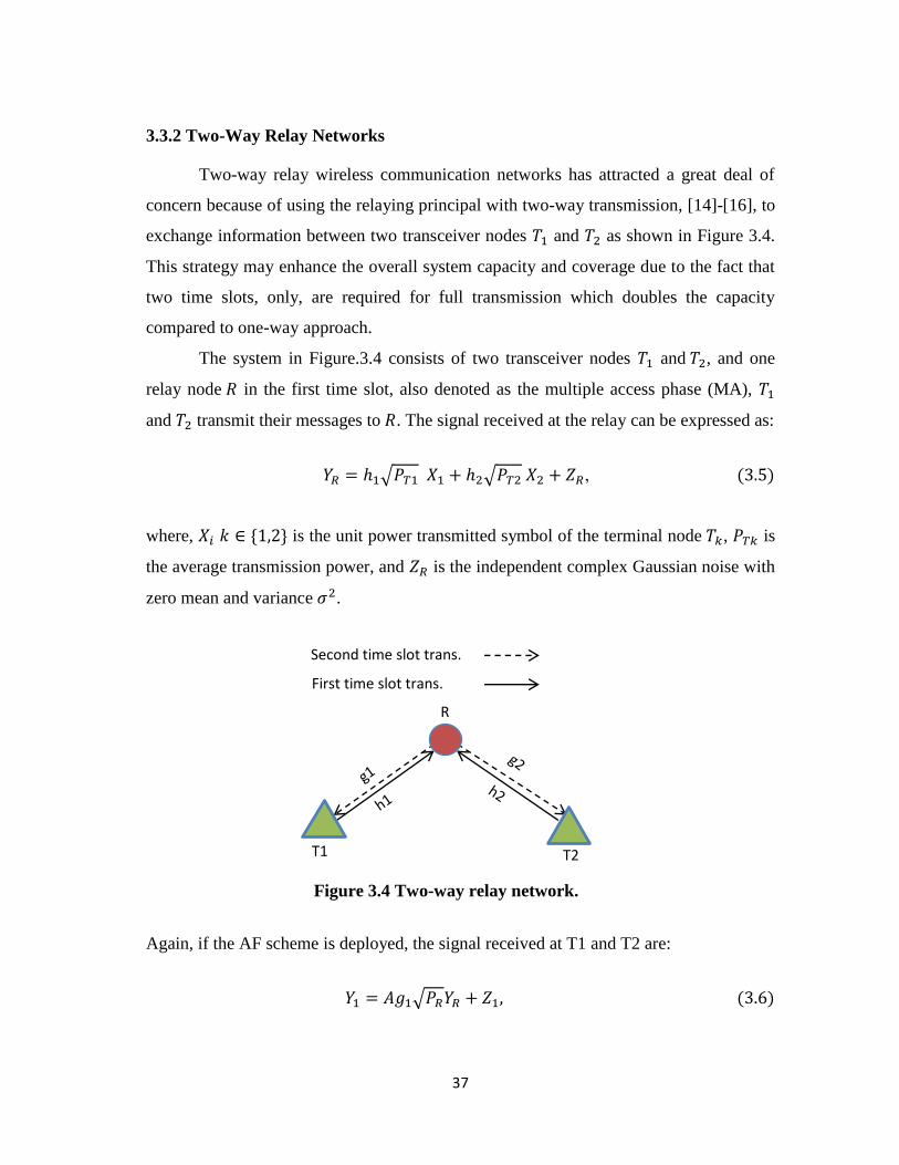
37
3.3.2 Two-Way Relay Networks
Two-way relay wireless communication networks has attracted a great deal of
concern because of using the relaying principal with two-way transmission, [14]-[16], to
exchange information between two transceiver nodes 1 and 2 as shown in Figure 3.4.
This strategy may enhance the overall system capacity and coverage due to the fact that
two time slots, only, are required for full transmission which doubles the capacity
compared to one-way approach.
The system in Figure.3.4 consists of two transceiver nodes 1 and 2, and one
relay node in the first time slot, also denoted as the multiple access phase (MA), 1
and 2 transmit their messages to . The signal received at the relay can be expressed as:
= 1√ 1 1 + 2√ 2 2 + ,
where, is the unit power transmitted symbol of the terminal node , is
the average transmission power, and is the independent complex Gaussian noise with
zero mean and variance 2.
Again, if the AF scheme is deployed, the signal received at T1 and T2 are:
1 = 1√ + 1
T1 T2
First time slot trans.
R
Second time slot trans.
Figure 3.4 Two-way relay network.

38
2 = 2√ + 2
where, denote the average transmission power of the relay node and is the
independent complex Gaussian noise with zero mean and variance 2
is the amplification factor expressed as
=1
√
After receiving the signals, each transceiver node is then extracts the desired
signal by canceling the self-interference.
Now, if the DF scheme is applied, the received signal at each node edge is given
by:
1 = 1√ + 1,
2 = 2√ + 2,
where denotes the unit-power transmitted symbol. No amplification factor is used
and the only noise faced is the independent complex Gaussian noise ,
39
Bibliography
[1] Tang, H., "Some physical layer issues of wide-band cognitive radio systems,"
2005 First IEEE International Symposium on New Frontiers in Dynamic
Spectrum Access Networks, 2005. DySPAN 2005., pp. 151-159, 8-11 Nov. 2005.
[2] Hong, Y-W.; Huang, W-J.; Chiu, F-H.; Kuo, C-C. J., "Cooperative
communications in resource-constrained wireless networks," IEEE Signal
Processing Magazine, vol. 24, no. 3, pp. 47-57, May 2007.
[3] Cimini, L. J., "Analysis and simulation of a digital mobile channel using
orthogonal frequency division multiplexing," IEEE Transactions
on Communications, vol. 33, no. 7, pp. 665-675, Jul 1985.
[4] Weinstein, S.; Ebert, P., "Data transmission by frequency-division multiplexing
using the discrete fourier transform," IEEE Transactions on Communication
Technology, vol. 19, no. 5, pp. 628-634, October 1971.
[5] Li, Y. G.; Stüber, G., “Orthogonal frequency division multiplexing for wireless
communications”. Boston, MA: Springer-Verlag, Jan. 2006.
[6] Hwang, T.; Yang, C.; Wu, G.; Li, S.; Li, G. Y., "OFDM and its wireless
applications: a survey," IEEE Transactions on Vehicular Technology, vol. 58,
no. 4, pp. 1673-1694, May2009.
[7] Goldsmith, A. “Wireless communications” Cambridge university press, (2005).
[8] Shaat, M., “Resource management in multicarrier based cognitive radio
systems,” PhD’s thesis, Universitat Polit`ecnica de Catalunya (UPC), Spain,
2012.
[9] Armstrong, J. “Peak-to-average power reduction for OFDM by repeated clipping
and frequency domain filtering,” Electron. Lett., vol. 38, no. 5, pp. 246–247, Feb.
2002.
[10] Bauml, R. W.; Fischer, R. F. H.; Huber, J. B., "Reducing the peak-to-average
power ratio of multicarrier modulation by selected mapping," Electronics Letters,
vol. 32, no. 22, pp.2056- 2057, 24 Oct 1996.
40
[11] Mestdagh, D. G.; Spruyt, P.; Biran, B., "Analysis of clipping effect in DMT-
based ADSL systems," IEEE International Conference on Communications,
1994. ICC '94, SUPERCOMM/ICC '94, Conference Record, 'Serving humanity
through communications.', pp. 293-300 vol. 1, 1-5 May 1994.
[12] Chakravarthy, V. D.; Shaw, A. K.; Temple, Michael A.; Stephens, J. P.,
"Cognitive radio-an adaptive waveform with spectral sharing capability," IEEE
Wireless Communications and Networking Conference, vol.2, no., pp.724,729
Vol. 2, 13-17 March 2005.
[13] Shaat, M.; Bader, F., "Joint subcarrier pairing and power allocation for DF-
relayed OFDM cognitive systems," 2011 IEEE Global Telecommunications
Conference (GLOBECOM 2011), pp. 1-6, 5-9 Dec. 2011.
[14] Vu, H. N.; Kong, H-Y., "Joint subcarrier matching and power allocation in
OFDM two-way relay systems," Journal of Communications and Networks, vol.
14, no. 3, pp. 257-266, June 2012.
[15] Pabst, R.; Walke, B. H.; Schultz, D. C.; Herhold, P.; Yanikomeroglu, H.;
Mukherjee, S.; Viswanathan, H.; Lott, M.; Zirwas, W.; Dohler, M.; Aghvami, H.;
Falconer, D. D.; Fettweis, G. P., "Relay-based deployment concepts for wireless
and mobile broadband radio," IEEE Communications Magazine, vol. 42, no. 9,
pp. 80-89, Sept. 2004.
[16] Oyman, O.; Laneman, N. J.; Sandhu, S., "Multihop relaying for broadband
wireless mesh networks: from theory to practice," IEEE Communications
Magazine, vol. 45, no. 11, pp. 116-122, November 2007.
[17] Xiong, K.; Fan, P.; Letaief, K.B.; Yi, S.; Lei, M., "Joint subcarrier-pairing and
resource allocation for two-way multi-relay OFDM networks," IEEE Global
Communications Conference (GLOBECOM), pp. 4874-4879, 3-7 Dec. 2012.
[18] Lu, H-C.; Liao, W., "On cooperative strategies in wireless relay networks," 2011
Proceedings IEEE INFOCOM, pp. 531-535, 10-15 April 2011.
41
CHAPTER FOUR
RESOURCE ALLOCATION IN OFDM-BASED COGNITIVE TWO-
WAY MULTIPLE-RELAY NETWORKS
4.1 Introduction
This chapter presents the main contribution of this thesis where a joint resource
allocation problem in AF OFDM based two-way multiple-relay CR network is
considered. Two transceiver nodes exchange information via relay nodes due to large
distance, existence of obstacles or worse channel conditions, between the two
transceiver nodes. The full transmission occurs in two phases MA and BC phases.
Considering individual power and interference constraints, the power allocation,
subcarrier pairing and relay assignment are jointly optimized to maximize the sum-rate.
In this study, the dual decomposition technique is applied to obtain the optimal
resource allocation. Additionally, suboptimal algorithms are introduced to perform the
allocation with much less complexity, compared to the optimal solution, and small
performance degradation. Simulation results and discussion are shown at the end of this
chapter to demonstrate the performance gain of the proposed algorithms.
4.2 Constrained Optimization
4.2.1 Duality Theory
In the communication systems, the duality theory concept is frequently used. The
main benefit of the dual algorithm is that it can be used to bound a non-convex problems
or decompose the main problem into a number of subproblems. Consider the following
primal problem:
42
The functions and are not necessarily convex or concave functions, is a constant
and is the variable to be optimized and is the optimal value.
The first step in the dual problem construction is finding the Lagrangian function
of a dual variable :
= − −
Then, the maximum value of the Lagrangian function is called the Lagrange dual
function which can be expressed as:
=
The Lagrange dual function gives an upper bound on the optimal value of the
problem (4.1) for every . Therefore, to find the lowest upper bound, the dual
problem is formed by minimizing the Lagrangian dual function as follows [4]:
=
>
Thus, the inequality
is always holds even if the original problem is not convex.
The duality gap is defined as the difference −
which defines the
gap between the optimal solution of the primal problem and the lowest upper bound on it
that can be obtained from the Lagrange dual function. The duality is called weak duality
when the original primal problem is not convex. The strong duality takes place if =
, i.e. the optimal duality gap is zero. If the primal problem is convex, the strong
duality usually holds.
43
For problem (4.1), when is concave and is convex, and there exists a
strictly feasible point in the constraints set, the primal and dual problems have the same
solution [5]. When the primal problem is not convex, the zero duality gap cannot be
guaranteed but if a non-convex problem satisfies the time sharing condition, the strong
duality holds.
4.2.2 Time Sharing Condition
Theorem 1 in [3] indicates that if an optimization problem satisfies the time-
sharing condition, then it has a zero duality gap, i.e., the primal problem and the dual
problem have the same optimal value.
The time sharing condition can be summarized as follows [3]: Assume that
and are the optimal solutions of the optimization problem (4.1) with = and
= respectively. The optimization problem (4.1) satisfies the time sharing
condition if for any = , = and for any , there is always exists a
feasible solution , such that + − and +
− .
For many practical optimization multicarrier problems, the time-sharing
condition is satisfied. Our problem, in this study, is satisfying the time sharing condition
for, sufficiently, large number of subcarriers regardless of the problem convexity implies
that the duality gap approaches zero. The dual problem can be solved instead of the
primal one when it is easier to be solved or when a closed form solution cannot be
found. Thus, in section 4.4 the dual method is used to solve the primal problem by
discussing its dual problem rather than itself.
4.2.3 Subgradient Method
The subgradient method is a very simple algorithm for minimizing a non-
differentiable convex function. The subgradient method can be used to solve inequality
constrained optimization problems e.g.
44
=
where are convex.
The subgradient of any function at the point is any vector that satisfies the
inequality [8]:
+ −
When is differentiable, is the gradient of at , i.e.
In order to solve (4.5) the subgradient performs the following update, at each
iteration, on the maximization variable
1 = + ,
where denotes the number of iterations, is the step size, and is a subgradient
of the objective or one of the constraint functions at and is given by [8]:
= {
=
for some such that >
where denotes the set of subgradients of at . From (4.5), if it is found that the
current point is a feasible solution, the objective subgradient is used. On the other hand,
if it is infeasible the subgradient of any violated constraint is chosen.
Moreover, the step size, which has to be set before the algorithm starts, has many
different types like constant step size with = , and diminishing step size rule
e.g. example of the diminishing step size rule is =
√ , where > .
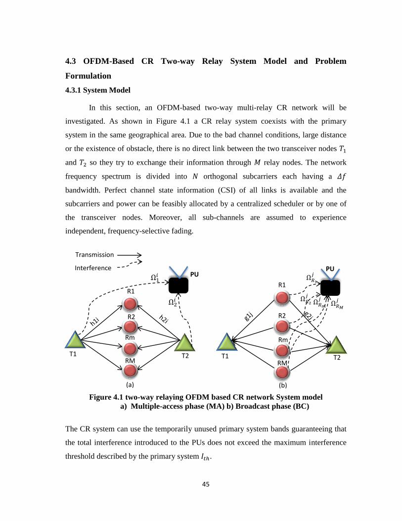
45
4.3 OFDM-Based CR Two-way Relay System Model and Problem
Formulation
4.3.1 System Model
In this section, an OFDM-based two-way multi-relay CR network will be
investigated. As shown in Figure 4.1 a CR relay system coexists with the primary
system in the same geographical area. Due to the bad channel conditions, large distance
or the existence of obstacle, there is no direct link between the two transceiver nodes 1
and 2 so they try to exchange their information through relay nodes. The network
frequency spectrum is divided into orthogonal subcarriers each having a
bandwidth. Perfect channel state information (CSI) of all links is available and the
subcarriers and power can be feasibly allocated by a centralized scheduler or by one of
the transceiver nodes. Moreover, all sub-channels are assumed to experience
independent, frequency-selective fading.
Figure 4.1 two-way relaying OFDM based CR network System model
a) Multiple-access phase (MA) b) Broadcast phase (BC)
The CR system can use the temporarily unused primary system bands guaranteeing that
the total interference introduced to the PUs does not exceed the maximum interference
threshold described by the primary system .
Transmission
Rm
T1 T2
R1
Interference PU
R2
RM
R1
T1 T2
PU
R2
Rm
RM
Ω1𝑖
Ω2𝑖
Ω𝑅
𝑗
Ω𝑅
𝑗 Ω𝑅𝑚
𝑗 Ω𝑅𝑀
𝑗
(a) (b)
46
The relay is assumed to be half-duplex, thus receiving and transmitting in two
different time slots. To complete a full exchange of information, two phases are
considered, the MA phase and the BC phase. In the MA phase, 1 and 2 transmit their
data, simultaneously, to the selected relay using the same subcarrier. In the BC
phase, the selected relay amplifies the received signals, and broadcasts them to the two
transceiver nodes. Once received, 1 and 2 can extract the required information by
canceling self-interference.
The relay node, , receives the combined signal on subcarrier in the MA
phase and then amplify and broadcast it on another subcarrier in the BC phase so
subcarrier-pairing scheme between the two phases is deployed where subcarrier in the
first time slot and its corresponding subcarrier in the second time slot will form a
subcarrier pair . Let 1 and 2
denote the channel coefficients over the
subcarrier from 1 and 2 to the relay node , respectively. Similarly 1 and 2
denote the channel coefficients over the subcarrier from the selected relay node to 1
and 2, respectively. Moreover, and
= are channel complex coefficients
between the transceiver nodes relay node and the PU, respectively. In order to
avoid the interference among the relays, each subcarrier pair is only allowed to be
allocated to one relay node, but not vice versa. Accordingly, more than one pair of
subcarriers may be assigned to a relay node.
In the MA phase, the received signal at the relay over subcarrier can
be expressed as:
= 1 √ 1
1 + 2 √ 2
2 + ,
where , , is the unit power transmitted symbol of the terminal node over
subcarrier , is the average transmission power, and is the independent complex
Gaussian noise with zero mean and variance 2
47
The received signal by the relay is then multiplied by amplification factor
expressed as [1]:
=1
√
The signal is then broadcasted to the transceivers. Once received the signals, the
transceiver nodes extract the desired signals by cancelling self-interference.
The received signals at the terminal nodes 1 and 2 over subcarrier in the BC
phase are given by
1 = 1 √
+ 1
2 = 2 √
+ 2
Where denote the average transmission power of the relay node over
subcarrier . Moreover, is the independent complex Gaussian noise with zero mean
and variance 2 at , on each subcarrier includes the noise caused by the
PUs transmission. Based on the central limit theorem, the PUs noise could be considered
as Gaussian noise. Without loss of generality, the noise variance is assumed to be
constant for all subcarriers, i.e. 2 =
2 = 2.
The received end-to-end signal to noise ratio (SNR) at 1 and 2 through over
the subcarrier pair can be given by the following equations [2]
1 =
(
)
2 =
(
)
respectively. Where 1 = | 1 |2 2 = | 2 |
2 3 = | 1 |2 4 = | 2 |
2.
48
The total end-to-end AF data rate on a given subcarrier pair that is allocated
to the relay,
, is expressed as [9]
=1
2 2 + 1 +
1
2 2 + 2
The pre-log factor of ( in equation (4.15) above, is due to the fact that two times slots
are required for the complete transmission process.
4.3.2 Problem Formulation
Let ( 1 2
) represents the average transmission power of nodes 1, 2
and the selected relay , respectively. All channel gains for the network can be adopted
by assuming classical channel estimation approach and all the noise variances assumed to
be equal 2 Denote as the relay selection indicator with =
represents that the subcarrier pair is allocated to the relay otherwise = .
Moreover, denote as the subcarrier-pairing indicator, that is, if subcarrier in
the first time slot is paired with subcarrier in the second time slot, then =
otherwise = .
Our objective is to jointly optimize the power, relay assignment and subcarrier
pairing to maximize the throughput of the multi-relay two-way OFDM CR system,
previously described, such that the instantaneous interference introduced to the primary
system is below the maximum tolerable threshold, . The primal optimization problem
of our system is expressed as:
0
∑∑ ∑
1
1
1
- (C1:Subcarrier pairing constraint):
∑
1
= and ∑
1
=
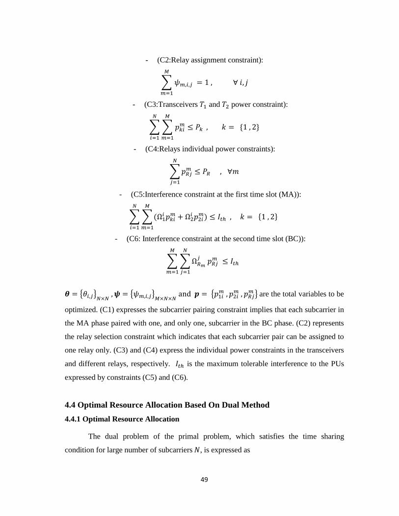
49
- (C2:Relay assignment constraint):
∑
1
=
- (C3:Transceivers 1 and 2 power constraint):
∑ ∑
1
1
=
- (C4:Relays individual power constraints):
∑
1
- (C5:Interference constraint at the first time slot (MA)):
∑ ∑ 1
+ 2 2
1
=
1
- (C6: Interference constraint at the second time slot (BC)):
∑ ∑
1
1
= { } = { }
= { 1 2
} are the total variables to be
optimized. (C1) expresses the subcarrier pairing constraint implies that each subcarrier in
the MA phase paired with one, and only one, subcarrier in the BC phase. (C2) represents
the relay selection constraint which indicates that each subcarrier pair can be assigned to
one relay only. (C3) and (C4) express the individual power constraints in the transceivers
and different relays, respectively. is the maximum tolerable interference to the PUs
expressed by constraints (C5) and (C6).
4.4 Optimal Resource Allocation Based On Dual Method
4.4.1 Optimal Resource Allocation
The dual problem of the primal problem, which satisfies the time sharing
condition for large number of subcarriers , is expressed as
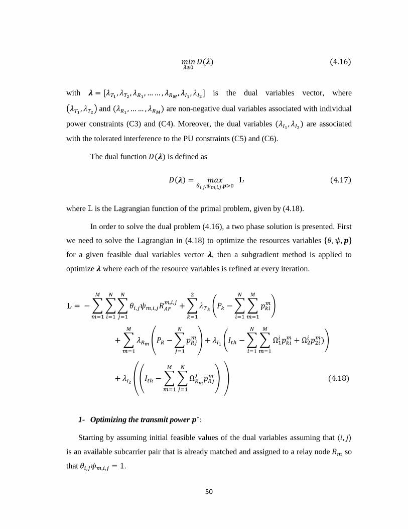
50
0
with =
is the dual variables vector, where
(
) and
are non-negative dual variables associated with individual
power constraints (C3) and (C4). Moreover, the dual variables are associated
with the tolerated interference to the PU constraints (C5) and (C6).
The dual function is defined as
= 0
where is the Lagrangian function of the primal problem, given by (4.18).
In order to solve the dual problem (4.16), a two phase solution is presented. First
we need to solve the Lagrangian in (4.18) to optimize the resources variables
for a given feasible dual variables vector , then a subgradient method is applied to
optimize where each of the resource variables is refined at every iteration.
= − ∑ ∑∑
1
1
1
+ ∑ ( − ∑ ∑
1
1
+
2
1
+ ∑
1
( − ∑
1
) + ( − ∑ ∑ 1
+ 2 2
1
1
+
+ (( − ∑ ∑
1
1
) ,
1- Optimizing the transmit power
Starting by assuming initial feasible values of the dual variables assuming that
is an available subcarrier pair that is already matched and assigned to a relay node so
that = .
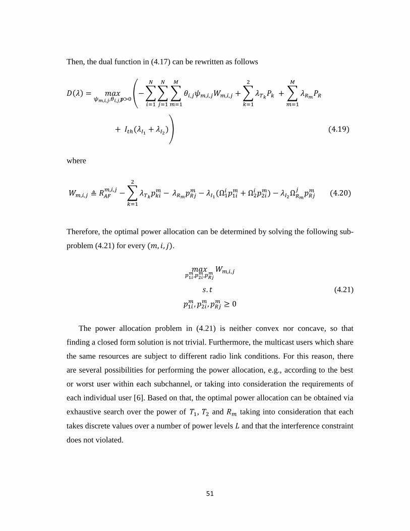
51
Then, the dual function in (4.17) can be rewritten as follows
= 0
(−∑∑ ∑
1
1
1
+ ∑
2
1
+ ∑
1
+ + )
where
− ∑
−
2
1
− 1 1
+ 2 2
−
Therefore, the optimal power allocation can be determined by solving the following sub-
problem (4.21) for every .
(4.21)
1 2
The power allocation problem in (4.21) is neither convex nor concave, so that
finding a closed form solution is not trivial. Furthermore, the multicast users which share
the same resources are subject to different radio link conditions. For this reason, there
are several possibilities for performing the power allocation, e.g., according to the best
or worst user within each subchannel, or taking into consideration the requirements of
each individual user [6]. Based on that, the optimal power allocation can be obtained via
exhaustive search over the power of 1, 2 and taking into consideration that each
takes discrete values over a number of power levels and that the interference constraint
does not violated.
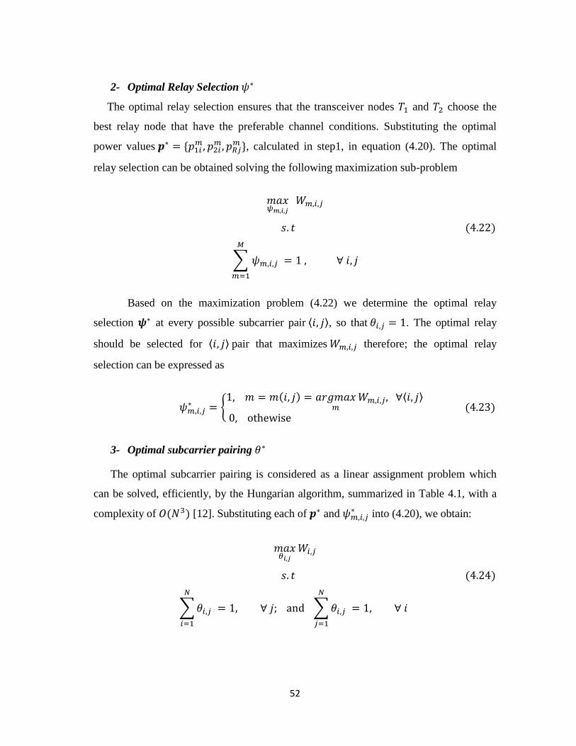
52
2- Optimal Relay Selection
The optimal relay selection ensures that the transceiver nodes 1 and 2 choose the
best relay node that have the preferable channel conditions. Substituting the optimal
power values = 1 2
, calculated in step1, in equation (4.20). The optimal
relay selection can be obtained solving the following maximization sub-problem
∑
1
=
Based on the maximization problem (4.22) we determine the optimal relay
selection at every possible subcarrier pair , so that = . The optimal relay
should be selected for pair that maximizes therefore; the optimal relay
selection can be expressed as
= {
= =
3- Optimal subcarrier pairing
The optimal subcarrier pairing is considered as a linear assignment problem which
can be solved, efficiently, by the Hungarian algorithm, summarized in Table 4.1, with a
complexity of 3 [12]. Substituting each of and into (4.20), we obtain:
∑
1
= ∑
1
=
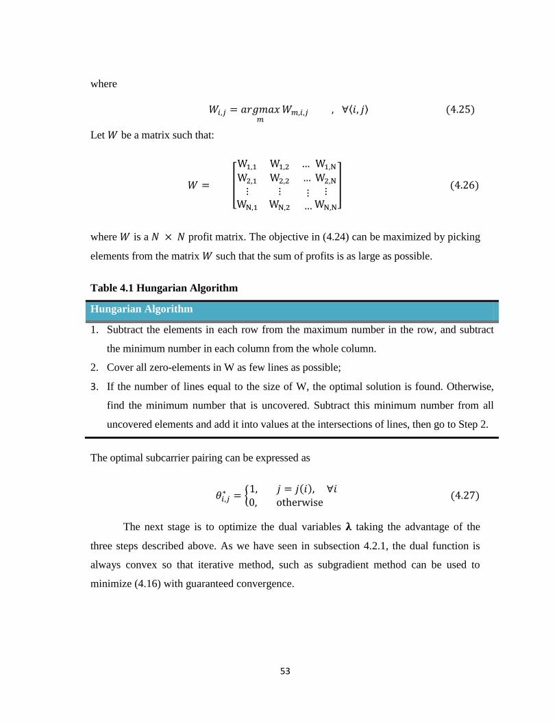
53
where
=
Let be a matrix such that:
= [
1 1 1 2
2 1 2 2
1
2
1
2
]
where is a profit matrix. The objective in (4.24) can be maximized by picking
elements from the matrix such that the sum of profits is as large as possible.
Table 4.1 Hungarian Algorithm
Hungarian Algorithm
1. Subtract the elements in each row from the maximum number in the row, and subtract
the minimum number in each column from the whole column.
2. Cover all zero-elements in W as few lines as possible;
3. If the number of lines equal to the size of W, the optimal solution is found. Otherwise,
find the minimum number that is uncovered. Subtract this minimum number from all
uncovered elements and add it into values at the intersections of lines, then go to Step 2.
The optimal subcarrier pairing can be expressed as
= {
=
The next stage is to optimize the dual variables taking the advantage of the
three steps described above. As we have seen in subsection 4.2.1, the dual function is
always convex so that iterative method, such as subgradient method can be used to
minimize (4.16) with guaranteed convergence.
54
4.4.2 Subgradient Method to Calculate the Optimal
Through the steps described in subsection 4.4.1, the optimal resource allocation
have been obtained, for a given initial values of the dual variable vector .
Substituting each of into (4.17), we obtain the dual function then solving the
optimization problem of the dual problem in (4.16), the optimal dual vector can be
found by the subgradient method. The sub-gradient method can be used to solve the dual
problem with guaranteed convergence, [8], since a dual function is always convex. Based
on initially selected dual variables vector, = 10 2
0 10
0 0
0 , can
be updated at the + iteration by as shown in the equations (4.28)-(4.31) below
1 =
− ( − ∑ ∑
1
1
+
1 =
− ( − ∑
1
)
1 =
− ( − (∑ ∑ 1
1
+ 1 2
1
1
+)
1 =
− ( − ∑ ∑
1
1
)
Where , step size of the iteration which can be updated according to the non-
summable diminishing step size policy [8].
The iterations are repeated until convergence. As a result, the optimal solution of
the primal problem is achieved. It should be noted that all the resources have
to be recalculated for every single iteration, under , in terms of the steps described in
subsection 4.4.1.
55
4.5 Suboptimal Algorithms
In fact, the significant weight of complexity in the optimal solution is, essentially,
in the power allocation and in the Hungarian algorithm. As a result, three suboptimal
algorithms are proposed based on this knowledge. In the three algorithms, the power of
the relays and transceivers is fixed to be uniformly distributed over subcarriers, rather
than the optimal allocation obtained in the previous section. Moreover, it is assumed that
the interference introduced to the PU by every subcarrier is uniform. Therefore, the single
subcarrier maximum allowable power should be the minimum between the interference
threshold and the node power upper bound divided by the total number of subcarriers, i.e.
= (
) =
Similarly,
= (
+
In the first suggested suboptimal, a greedy suboptimal algorithm is proposed in
which the subcarriers are matched by ordering the subcarriers in the first and second time
slots according to maximum achieved rate . The subcarrier pairing, in the next
suggested algorithm is obtained using the Hungarian method. Finally, in the third
suboptimal algorithm the pairing is done using the same subcarrier in, both, the first and
second time slots.
4.5.1 Proposed Suboptimal Greedy Algorithm (Proposed Suboptimal)
The subcarrier matching in this algorithm is performed in an efficient way
depending on the value of the rate
in (4.15). Once the power levels are determined,
equations (4.32) and (4.33), the algorithm searches for the best second time slot
subcarrier, , and relay that maximizes the product of 1 and 2 in the rate
equation (4.15). By defining A and B sets that include all the non-assigned subcarriers in
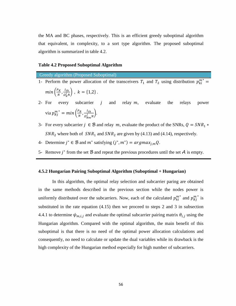
56
the MA and BC phases, respectively. This is an efficient greedy suboptimal algorithm
that equivalent, in complexity, to a sort type algorithm. The proposed suboptimal
algorithm is summarized in table 4.2.
Table 4.2 Proposed Suboptimal Algorithm
Greedy algorithm (Proposed Suboptimal)
1- Perform the power allocation of the transceivers 1 and 2 using distribution
=
(
* = .
2- For every subcarrier and relay , evaluate the relays power
via
= (
*.
3- For every subcarrier B and relay , evaluate the product of the SNRs, = 1
2 where both of 1 and 2 are given by (4.13) and (4.14), respectively.
4- Determine B and satisfying = .
5- Remove from the set B and repeat the previous procedures until the set A is empty.
4.5.2 Hungarian Pairing Suboptimal Algorithm (Suboptimal + Hungarian)
In this algorithm, the optimal relay selection and subcarrier paring are obtained
in the same methods described in the previous section while the nodes power is
uniformly distributed over the subcarriers. Now, each of the calculated
and
is
substituted in the rate equation (4.15) then we proceed to steps 2 and 3 in subsection
4.4.1 to determine and evaluate the optimal subcarrier pairing matrix using the
Hungarian algorithm. Compared with the optimal algorithm, the main benefit of this
suboptimal is that there is no need of the optimal power allocation calculations and
consequently, no need to calculate or update the dual variables while its drawback is the
high complexity of the Hungarian method especially for high number of subcarriers.
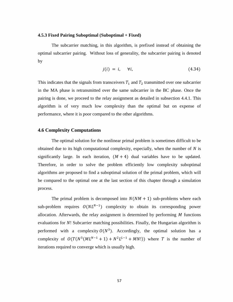
57
4.5.3 Fixed Pairing Suboptimal (Suboptimal + Fixed)
The subcarrier matching, in this algorithm, is prefixed instead of obtaining the
optimal subcarrier pairing. Without loss of generality, the subcarrier pairing is denoted
by
=
This indicates that the signals from transceivers 1 and 2 transmitted over one subcarrier
in the MA phase is retransmitted over the same subcarrier in the BC phase. Once the
pairing is done, we proceed to the relay assignment as detailed in subsection 4.4.1. This
algorithm is of very much low complexity than the optimal but on expense of
performance, where it is poor compared to the other algorithms.
4.6 Complexity Computations
The optimal solution for the nonlinear primal problem is sometimes difficult to be
obtained due to its high computational complexity, especially, when the number of is
significantly large. In each iteration, + dual variables have to be updated.
Therefore, in order to solve the problem efficiently low complexity suboptimal
algorithms are proposed to find a suboptimal solution of the primal problem, which will
be compared to the optimal one at the last section of this chapter through a simulation
process.
The primal problem is decomposed into + sub-problems where each
sub-problem requires 1 complexity to obtain its corresponding power
allocation. Afterwards, the relay assignment is determined by performing functions
evaluations for Subcarrier matching possibilities. Finally, the Hungarian algorithm is
performed with a complexity 3 . Accordingly, the optimal solution has a
complexity of 3 1 + + 2 1 + where is the number of
iterations required to converge which is usually high.
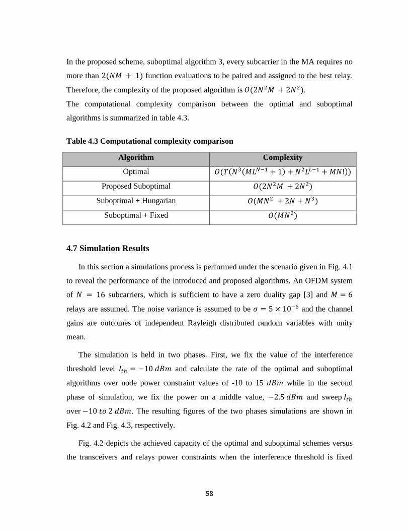
58
In the proposed scheme, suboptimal algorithm 3, every subcarrier in the MA requires no
more than + function evaluations to be paired and assigned to the best relay.
Therefore, the complexity of the proposed algorithm is 2 + 2 .
The computational complexity comparison between the optimal and suboptimal
algorithms is summarized in table 4.3.
Table 4.3 Computational complexity comparison
Algorithm Complexity
Optimal 3 1 + + 2 1 +
Proposed Suboptimal 2 + 2
Suboptimal + Hungarian 2 + + 3
Suboptimal + Fixed 2
4.7 Simulation Results
In this section a simulations process is performed under the scenario given in Fig. 4.1
to reveal the performance of the introduced and proposed algorithms. An OFDM system
of = subcarriers, which is sufficient to have a zero duality gap [3] and =
relays are assumed. The noise variance is assumed to be = and the channel
gains are outcomes of independent Rayleigh distributed random variables with unity
mean.
The simulation is held in two phases. First, we fix the value of the interference
threshold level = − and calculate the rate of the optimal and suboptimal
algorithms over node power constraint values of -10 to 15 while in the second
phase of simulation, we fix the power on a middle value, − and sweep
over − . The resulting figures of the two phases simulations are shown in
Fig. 4.2 and Fig. 4.3, respectively.
Fig. 4.2 depicts the achieved capacity of the optimal and suboptimal schemes versus
the transceivers and relays power constraints when the interference threshold is fixed
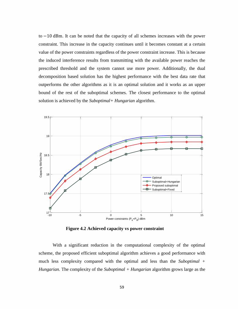
59
to − . It can be noted that the capacity of all schemes increases with the power
constraint. This increase in the capacity continues until it becomes constant at a certain
value of the power constraints regardless of the power constraint increase. This is because
the induced interference results from transmitting with the available power reaches the
prescribed threshold and the system cannot use more power. Additionally, the dual
decomposition based solution has the highest performance with the best data rate that
outperforms the other algorithms as it is an optimal solution and it works as an upper
bound of the rest of the suboptimal schemes. The closest performance to the optimal
solution is achieved by the Suboptimal+ Hungarian algorithm.
Figure 4.2 Achieved capacity vs power constraint
With a significant reduction in the computational complexity of the optimal
scheme, the proposed efficient suboptimal algorithm achieves a good performance with
much less complexity compared with the optimal and less than the Suboptimal +
Hungarian. The complexity of the Suboptimal + Hungarian algorithm grows large as the
-10 -5 0 5 10 1517
17.5
18
18.5
19
19.5
Power constraints (Pk=P
R) dBm
Capacity B
it/S
ec/H
z
Optimal
Suboptimal+Hungarian
Proposed suboptimal
Suboptimal+Fixed
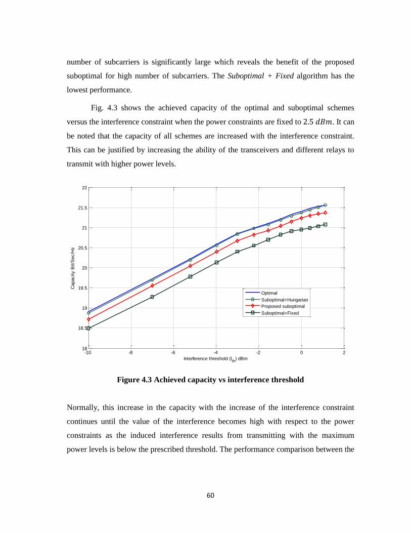
60
number of subcarriers is significantly large which reveals the benefit of the proposed
suboptimal for high number of subcarriers. The Suboptimal + Fixed algorithm has the
lowest performance.
Fig. 4.3 shows the achieved capacity of the optimal and suboptimal schemes
versus the interference constraint when the power constraints are fixed to . It can
be noted that the capacity of all schemes are increased with the interference constraint.
This can be justified by increasing the ability of the transceivers and different relays to
transmit with higher power levels.
Figure 4.3 Achieved capacity vs interference threshold
Normally, this increase in the capacity with the increase of the interference constraint
continues until the value of the interference becomes high with respect to the power
constraints as the induced interference results from transmitting with the maximum
power levels is below the prescribed threshold. The performance comparison between the
-10 -8 -6 -4 -2 0 218
18.5
19
19.5
20
20.5
21
21.5
22
Interference threshold (Ith
) dBm
Capacity B
it/S
ec/H
z
Optimal
Suboptimal+Hungarian
Proposed suboptimal
Suboptimal+Fixed

61
different simulated algorithms follows the same behavior described for Fig. 4.2 where the
complexity and performance has a tradeoff relationship.
62
Bibliography
[1] Xiong, K.; Fan, P.; Letaief, K.B.; Yi, S.; Lei, M., "Joint subcarrier-pairing and
resource allocation for two-way multi-relay OFDM networks," 2012 IEEE
Global Communications Conference (GLOBECOM), pp. 4874-4879, 3-7 Dec.
2012.
[2] Jiang, Q.; Liao, X.; Chen, H., "Joint power allocation and subcarrier assignment
for two-way OFDM multi-relay system," IEEE Wireless Communications and
Networking Conference (WCNC), pp. 709-714, 7-10 April 2013.
[3] Yu, W.; Lui, R., "Dual methods for nonconvex spectrum optimization of
multicarrier systems," IEEE Transactions on Communications, vol. 54, no. 7, pp.
1310-1322, July 2006.
[4] Shaat, M.; Bader, C. F., “Resource management in multicarrier based cognitive
radio systems”, 2012.
[5] Boyd, S.; Vandenberghe, L., “Convex optimization,” Cambridge Univ. Press,
Cambridge, U.K., 2004.
[6] Silva, Y. C. B.; Klein, A., "Power allocation in multi-carrier networks with
unicast and multicast services," IEEE International Conference on
Communications. ICC '07. , pp. 5433-5438, 24-28 June 2007.
[7] Khun, H., “The Hungarian method for the assignment problems,” Naval
Research Logistics Quarterly 2, pp. 83C97-1955.
[8] Boyd, S; Mutapcic, A., “Subgradient methods,” notes for EE364, Standford
University, winter. 2006-07.
[9] Ubaidulla, P.; Aissa, S., "optimal relay selection and power allocation for
cognitive two-way relaying networks," IEEE Wireless Communications Letters,
vol. 1, no. 3, pp. 225-228, June 2012.
63
CHAPTER FIVE
CONCLUSION AND FUTURE WORK
5.1 Conclusion
Chapter 2
In this chapter, an overview of the CR technique was presented. A description of
the cognitive networks characteristics was introduced; include the cognitive capability
and reconfigurability. Moreover, the network architecture and cognitive cycle were also
discussed, where the main cycle stages, spectrum sensing, spectrum decision, spectrum
sharing and spectrum mobility, are viewed in details. Finally, some of the current CR
applications were exhibited.
Chapter 3
The OFDM technique features, advantages and drawbacks were showed in this
chapter. Additionally, the important fields of OFDM applications were presented.
Furthermore, we continued in the chapter by a brief entrance to the relaying networks
showing its main transmission schemes, AF and DF. The common network types, one-
way and two-way relaying networks where mathematically detailed. At the end of
chapter 3, a recall of the main works in literature that is related to this dissertation
approach was presented.
Chapter 4
In this chapter, the main contribution of this thesis was presented where a joint
resource allocation problem in AF two-way multiple-relay OFDM CR system has been
investigated where power allocation, subcarrier pairing and relay assignment were
jointly optimized. The main optimization problem is formulated in order to maximize
the total end-to-end throughput of the system subject to individual power and
64
interference constraints. The dual decomposition approach is applied to solve the mixed
integer programming problem and achieve an optimal solution. Due to the high
computational complexity of the optimal scheme, calculated to be 3 1 +
+ 2 1 + , suboptimal algorithms were proposed based on distributing the
power uniformly over the total number of subcarriers, considering the interference
constraints, to achieve acceptable performance with much less complexity than the
optimal one. A greedy suboptimal algorithm was introduced where the subcarrier pairing
was done by searching for the best second time slot subcarrier. The proposed greedy
suboptimal was of complexity 2 + 2 which has much less than the optimal
with efficient performance as demonstrated in the simulation results subsection.
5.2 Future Works
In this dissertation, a scenario that gathers CR, OFDM technique and two-way
relaying has been considered. To the best of our knowledge, there is no significant work
in such scenario. However, there are still many open issues to analyze. In the following,
some important future research directions are listed
The decode an forward (DF) scenario is considered as a possible and attractive
future work extension where the rate expression has to be modified to suit this
technique and the rest of the power allocation, relay assignment and subcarrier
pairing can be optimized using similar approach.
In this thesis, it is considered that the resource allocation is performed in a
centralized way. The distributed allocation algorithms are of a considerable
interest. According to the formulation of the problem. The distributed allocation
algorithm might be derived from the centralized one [1]-[3]. The user, in this
approach, reserves the channel by sending a flag packet to all other the users.
Alternatively, game theoretic approaches can be used in the design of such
algorithms [4–6].
65
In fact, the assumption of perfect CSI and channel occupancy information
knowledge is not realistic. There is always exists some uncertainty in this
information due to the sensing errors or due to the unreliable feedback channel.
As a result, the effect of this lack of perfect information should be taken into
consideration and analyzed in order to determine the appropriate algorithms
required. In [7], the imperfect CSI and sensing information is considered to find
the optimal power allocation in OFDM based CR systems. The extensions of
these results to consider the two way relay scheme are a good step forward. The
CSI imperfection issues besides the way of exchanging the channels information
between the PUs and the SUs are still open problems that need more search and
investigation.
In this study, the dual-hop DF scenario was considered. The multiple-hop
network is a natural extension. More relaying protocols may have to be studied
like the adaptive relaying. In the adaptive relying [8–10], the relay node decides
the forwarding scheme based on the instantaneous channel quality and the
decoding ability.
66
Bibliography
[1] Cheng, P. Z.; Zhang, H. H.; Chen; Qiu, P., “Optimal distributed joint frequency,
rate and power allocation in cognitive OFDMA systems,” IET Communications,
vol. 2, no. 6, pp. 815–826, 2008.
[2] Ngo, D. T.; Tho, L-N., “Distributed resource allocation for cognitive radio
networks with spectrum-sharing constraints,” IEEE Transactions on Vehicular
Technology, vol. 60, no. 7, pp. 3436–3449, Sept. 2011.
[3] Zhang, Y.; Leung, C., “A distributed algorithm for resource allocation in OFDM
cognitive radio systems,” IEEE Transactions on Vehicular Technology, vol. 60,
no. 2, pp. 546–554, 2011.
[4] Lin, Y. Y.; Chen, K. C., “Distributed spectrum sharing in cognitive radio
networks-game theoretical view,” in 7th IEEE Consumer Communications and
Networking Conference (CCNC’10), 2010, pp. 1–5.
[5] Ko, C. H.; Wei, H. Y., “Game theoretical resource allocation for inter-bs
coexistence in IEEE 802.22,” IEEE Transactions on Vehicular Technology, vol.
59, no. 4, pp. 1729– 1744, 2010.
[6] Wang, J.; Scutari, G.; Palomar, D. P., “Robust MIMO cognitive radio via game
theory,” IEEE Transactions on Signal Processing, vol. 59, no. 3, pp. 1183–1201,
2011.
[7] Ruan, L.; Lau, V. K. N., “Power control and performance analysis of cognitive
radio systems under dynamic spectrum activity and imperfect knowledge of
system state,” IEEE Transactions on Wireless Communications, vol. 8, no. 9, pp.
4616–4622, 2009.
[8] Can, B.; Yomo, H.; Carvalho, E. D., “Hybrid forwarding scheme for cooperative
relaying in OFDM based networks,” in IEEE International Conference on
Communications (ICC’06), 2006, vol. 10, pp. 4520–4525.
[9] Li, Y.; Vucetic, B.; Chen, Z.; Yuan, J.; “An improved relay selection scheme
with hybrid relaying protocols,” in IEEE Global Telecommunications
Conference (GLOBECOM’07), 2007, pp. 3704–3708.

67
[10] Khan, Kuhn, V., “Power optimization in adaptive relay networks,” in IEEE
Global Telecommunications Conference (GLOBECOM’10), Dec. 2010, pp. 1–5.
Joint Resource Allocation in Multicarrier BasedCognitive Networks with Two-Way Relaying
Ahmed Jendeya∗, Musbah Shaat∗∗, Ammar Abu Hdrouss∗ and Faouzi Bader+
∗Islamic University of Gaza, Palestine∗∗Centre Tecnologic de Telecomunicacions de Catalunya, Spain
+SUPELEC, Rennes-France
Emails: [email protected], [email protected], [email protected], [email protected]
Abstract—In this paper, a joint resource allocation problemin amplify and forward (AF) OFDM based two-way multiple-relay cognitive radio network is considered, where two transceivernodes exchange information via a relay node. The full trans-mission happens in two phases: Multiple Access (MA) phaseand the Broadcast (BC) phase. Considering individual powerand interference constraints, the power allocation, subcarrierpairing and relay selection are jointly optimized in order tomaximize the sum-rate. The dual decomposition technique isapplied to obtain the optimal solution. Additionally, an efficientsuboptimal algorithm is proposed to reduce the computationalcomplexity of the optimal solution with a small performancedegradation. Finally, simulation results are shown to demonstratethe performance gain of the proposed algorithm.
Keywords—Cognitive Radio, OFDM, Two-way relaying, re-source allocation.
I. INTRODUCTION
Cognitive radio (CR), nowadays, is considered as one ofthe most promising techniques which enables flexible usageof radio spectrum and improves the spectral efficiency byenabling unlicensed users to exploit the licensed spectrum inan opportunistic manner. In Cognitive radio (CR) networks, asecondary user (SU) coexists in the same geographical areawith a primary user (PU) exploiting the spectrum holes in thelicensed spectrum band. The SUs are allowed to communicateusing these frequency slots as long as they do not causeharmful interference to the PUs. The CR principle can beapplied in a relay network specially when there is no directlink between nodes that need to exchange information. Instead,intermediate nodes act as relays such that they guarantee betterchannel conditions and less transmission power, implies lowlevel of interference caused to PUs than the direct transmissioncase.
Relay networks main contribution is the utilization of thespatial diversity gains inherited in multiuser systems withoutthe need of multiple-antenna per node The relying schemesare divided, generally, into two main categories: one-way andtwo-way relay networks. In one-way relaying, the relay nodesreceive a signal from a source node in the first time slotand retransmit it to a destination node in the second timeslot, using the common cooperative schemes like decode andforward (DF) or amplify and forward (AF), which takes twotime slots for one direction transmission. Consequently, in one-way relaying, four time slots are needed if two nodes wantto establish full transmission since they cannot transmit at thesame time. On the other hand, in the two-way relaying scheme
the relay nodes receive signals from transceivers in the firsttime slot, also called multiple access phase (MA), and then inthe second time slot -broadcast phase (BC)- they broadcast thereceived signals to the transceivers. This overcomes the one-way relay scheme and doubles the spectral efficiency since twotime slots, only, are needed to full exchange of informationbetween the two nodes. Employing the OFDM techniqueincreases the spectral efficiency by transmitting informationover multiple orthogonal narrowband subcarriers besides beingvery effective in mitigating inter-symbol interference (ISI) andcombating frequency selective fading.
Resource allocation in relay communication networks hasextensively discussed in literature. In [1], Shaat and Baderdiscussed the joint power and subcarrier allocation in OFDMbased cognitive one-way relay network. Vu and Kong studiedin [2] the optimal power allocation in non-cognitive two-waydecode-and-forward OFDM relay network where three timeslot transmission is considered. In [3] , a joint resource alloca-tion was designed in AF OFDM based two-way non cognitivesystem where power allocation, subcarriers assignment andrelay selection are jointly optimized. Jang et al. showed in [4] atwo-step approach to power allocation for OFDM two-way AFnetwork where a total power constraint scenario is proposed.In [5], Ubaidulla and Aissa proposed a joint relay selectionand optimal power allocation among the SU nodes in a two-way relay CR network achieving maximum throughput undertransmit power and PU interference constraints. Multiuser two-way AF relay methods for beamforming systems were dis-cussed in [6] where multiple-input multiple outputs (MIMO)relay transceiver processing was proposed. Ho et al. in [7]considered an AF scheme for two-way relaying over OFDM, inwhich two nodes exchange information via a relay where theyperformed power allocation for the relay and transceiver nodes.The work in [2], [6], and in [7] discuss two-way relayingsystems in non-cognitive environment which is not efficient incognitive one due to the additional interference constraint. Atwo-way relay network in CR system was adopted in [8], wherelinear signal processing is done at the relay station to removeinter-pair interference for SUs and a power control algorithm isemployed to maximize the sum rate of the secondary networkwhile ensuring no harmful interference is introduced to PUs.The work in [5] and [8] is not valid for the multicarriersystems.
The main contribution of this paper is to jointly optimizethe power, for transceivers and relay nodes, subcarrier pairing
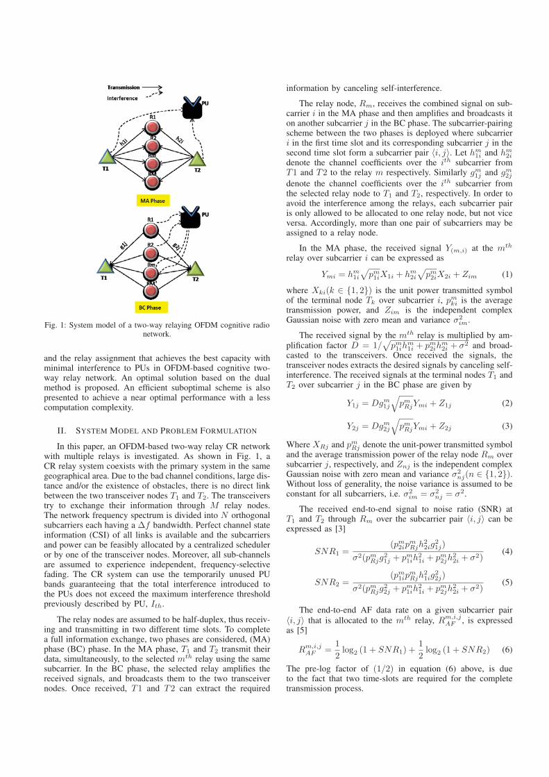
Fig. 1: System model of a two-way relaying OFDM cognitive radionetwork.
and the relay assignment that achieves the best capacity withminimal interference to PUs in OFDM-based cognitive two-way relay network. An optimal solution based on the dualmethod is proposed. An efficient suboptimal scheme is alsopresented to achieve a near optimal performance with a lesscomputation complexity.
II. SYSTEM MODEL AND PROBLEM FORMULATION
In this paper, an OFDM-based two-way relay CR networkwith multiple relays is investigated. As shown in Fig. 1, aCR relay system coexists with the primary system in the samegeographical area. Due to the bad channel conditions, large dis-tance and/or the existence of obstacles, there is no direct linkbetween the two transceiver nodes T1 and T2. The transceiverstry to exchange their information through M relay nodes.The network frequency spectrum is divided into N orthogonalsubcarriers each having a Δf bandwidth. Perfect channel stateinformation (CSI) of all links is available and the subcarriersand power can be feasibly allocated by a centralized scheduleror by one of the transceiver nodes. Moreover, all sub-channelsare assumed to experience independent, frequency-selectivefading. The CR system can use the temporarily unused PUbands guaranteeing that the total interference introduced tothe PUs does not exceed the maximum interference thresholdpreviously described by PU, Ith.
The relay nodes are assumed to be half-duplex, thus receiv-ing and transmitting in two different time slots. To completea full information exchange, two phases are considered, (MA)phase (BC) phase. In the MA phase, T1 and T2 transmit theirdata, simultaneously, to the selected mth relay using the samesubcarrier. In the BC phase, the selected relay amplifies thereceived signals, and broadcasts them to the two transceivernodes. Once received, T1 and T2 can extract the required
information by canceling self-interference.
The relay node, Rm, receives the combined signal on sub-carrier i in the MA phase and then amplifies and broadcasts iton another subcarrier j in the BC phase. The subcarrier-pairingscheme between the two phases is deployed where subcarrieri in the first time slot and its corresponding subcarrier j in thesecond time slot form a subcarrier pair 〈i, j〉. Let hm1i and hm2idenote the channel coefficients over the ith subcarrier fromT1 and T2 to the relay m respectively. Similarly gm1j and gm2jdenote the channel coefficients over the ith subcarrier fromthe selected relay node to T1 and T2, respectively. In order toavoid the interference among the relays, each subcarrier pairis only allowed to be allocated to one relay node, but not viceversa. Accordingly, more than one pair of subcarriers may beassigned to a relay node.
In the MA phase, the received signal Y(m,i) at the mth
relay over subcarrier i can be expressed as
Ymi = hm1i√pm1iX1i + hm2i
√pm2iX2i + Zim (1)
where Xki(k ∈ {1, 2}) is the unit power transmitted symbolof the terminal node Tk over subcarrier i, pmki is the averagetransmission power, and Zim is the independent complexGaussian noise with zero mean and variance σ2
im.
The received signal by the mth relay is multiplied by am-plification factor D = 1/
√pm1ih
m1i + pm2ih
m2i + σ2 and broad-
casted to the transceivers. Once received the signals, thetransceiver nodes extracts the desired signals by canceling self-interference. The received signals at the terminal nodes T1 andT2 over subcarrier j in the BC phase are given by
Y1j = Dgm1j
√pmRjYmi + Z1j (2)
Y2j = Dgm2j
√pmRjYmi + Z2j (3)
Where XRj and pmRj denote the unit-power transmitted symboland the average transmission power of the relay node Rm oversubcarrier j, respectively, and Znj is the independent complexGaussian noise with zero mean and variance σ2
nj(n ∈ {1, 2}).Without loss of generality, the noise variance is assumed to beconstant for all subcarriers, i.e. σ2
im = σ2nj = σ2.
The received end-to-end signal to noise ratio (SNR) atT1 and T2 through Rm over the subcarrier pair 〈i, j〉 can beexpressed as [3]
SNR1 =(pm2ip
mRjh
22ig
21j)
σ2(pmRjg21j + pm1ih
21i + pm2jh
22i + σ2)
(4)
SNR2 =(pm1ip
mRjh
21ig
22j)
σ2(pmRjg22j + pm1ih
21i + pm2jh
22i + σ2)
(5)
The end-to-end AF data rate on a given subcarrier pair〈i, j〉 that is allocated to the mth relay, Rm,i,jAF , is expressedas [5]
Rm,i,jAF =1
2log2 (1 + SNR1) +
1
2log2 (1 + SNR2) (6)
The pre-log factor of (1/2) in equation (6) above, is dueto the fact that two time-slots are required for the completetransmission process.
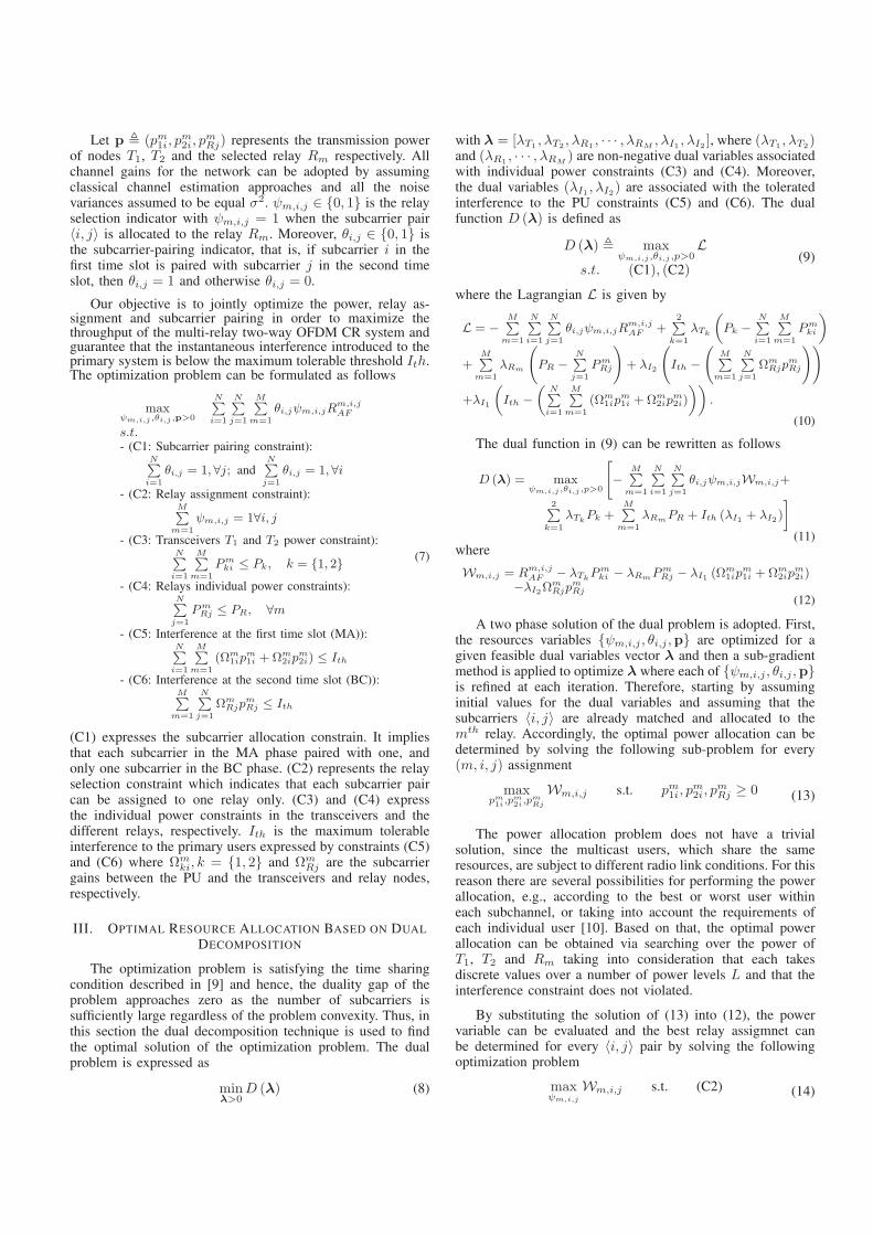
Let p � (pm1i, pm2i, p
mRj) represents the transmission power
of nodes T1, T2 and the selected relay Rm respectively. Allchannel gains for the network can be adopted by assumingclassical channel estimation approaches and all the noisevariances assumed to be equal σ2. ψm,i,j ∈ {0, 1} is the relayselection indicator with ψm,i,j = 1 when the subcarrier pair〈i, j〉 is allocated to the relay Rm. Moreover, θi,j ∈ {0, 1} isthe subcarrier-pairing indicator, that is, if subcarrier i in thefirst time slot is paired with subcarrier j in the second timeslot, then θi,j = 1 and otherwise θi,j = 0.
Our objective is to jointly optimize the power, relay as-signment and subcarrier pairing in order to maximize thethroughput of the multi-relay two-way OFDM CR system andguarantee that the instantaneous interference introduced to theprimary system is below the maximum tolerable threshold Ith.The optimization problem can be formulated as follows
maxψm,i,j ,θi,j ,p>0
N∑i=1
N∑j=1
M∑m=1
θi,jψm,i,jRm,i,jAF
s.t.- (C1: Subcarrier pairing constraint):
N∑i=1
θi,j = 1, ∀j; andN∑
j=1
θi,j = 1, ∀i- (C2: Relay assignment constraint):
M∑m=1
ψm,i,j = 1∀i, j- (C3: Transceivers T1 and T2 power constraint):
N∑i=1
M∑m=1
Pmki ≤ Pk, k = {1, 2}
- (C4: Relays individual power constraints):N∑
j=1
PmRj ≤ PR, ∀m
- (C5: Interference at the first time slot (MA)):N∑i=1
M∑m=1
(Ωm1ip
m1i +Ωm
2ipm2i) ≤ Ith
- (C6: Interference at the second time slot (BC)):M∑
m=1
N∑j=1
ΩmRjp
mRj ≤ Ith
(7)
(C1) expresses the subcarrier allocation constrain. It impliesthat each subcarrier in the MA phase paired with one, andonly one subcarrier in the BC phase. (C2) represents the relayselection constraint which indicates that each subcarrier paircan be assigned to one relay only. (C3) and (C4) expressthe individual power constraints in the transceivers and thedifferent relays, respectively. Ith is the maximum tolerableinterference to the primary users expressed by constraints (C5)and (C6) where Ωmki, k = {1, 2} and ΩmRj are the subcarriergains between the PU and the transceivers and relay nodes,respectively.
III. OPTIMAL RESOURCE ALLOCATION BASED ON DUAL
DECOMPOSITION
The optimization problem is satisfying the time sharingcondition described in [9] and hence, the duality gap of theproblem approaches zero as the number of subcarriers issufficiently large regardless of the problem convexity. Thus, inthis section the dual decomposition technique is used to findthe optimal solution of the optimization problem. The dualproblem is expressed as
minλ>0
D (λ) (8)
with λ = [λT1 , λT2 , λR1 , · · · , λRM, λI1 , λI2 ], where (λT1 , λT2)
and (λR1 , · · · , λRM ) are non-negative dual variables associatedwith individual power constraints (C3) and (C4). Moreover,the dual variables (λI1 , λI2) are associated with the toleratedinterference to the PU constraints (C5) and (C6). The dualfunction D (λ) is defined as
D (λ) � maxψm,i,j ,θi,j ,p>0
Ls.t. (C1), (C2)
(9)
where the Lagrangian L is given by
L = −M∑
m=1
N∑i=1
N∑j=1
θi,jψm,i,jRm,i,jAF +
2∑k=1
λTk
(Pk −
N∑i=1
M∑m=1
Pmki
)
+M∑
m=1
λRm
(PR −
N∑j=1
PmRj
)+ λI2
(Ith −
(M∑
m=1
N∑j=1
ΩmRjp
mRj
))
+λI1
(Ith −
(N∑i=1
M∑m=1
(Ωm1ip
m1i +Ωm
2ipm2i)
)).
(10)
The dual function in (9) can be rewritten as follows
D (λ) = maxψm,i,j ,θi,j ,p>0
[−
M∑m=1
N∑i=1
N∑j=1
θi,jψm,i,jWm,i,j+
2∑k=1
λTkPk +M∑
m=1
λRmPR + Ith (λI1 + λI2)
](11)
where
Wm,i,j = Rm,i,jAF − λTkP
mki − λRmPm
Rj − λI1 (Ωm1ip
m1i +Ωm
2ipm2i)
−λI2ΩmRjp
mRj
(12)
A two phase solution of the dual problem is adopted. First,the resources variables {ψm,i,j , θi,j ,p} are optimized for agiven feasible dual variables vector λ and then a sub-gradientmethod is applied to optimize λ where each of {ψm,i,j , θi,j ,p}is refined at each iteration. Therefore, starting by assuminginitial values for the dual variables and assuming that thesubcarriers 〈i, j〉 are already matched and allocated to themth relay. Accordingly, the optimal power allocation can bedetermined by solving the following sub-problem for every(m, i, j) assignment
maxpm1i,p
m2i,p
mRj
Wm,i,j s.t. pm1i, pm2i, p
mRj ≥ 0 (13)
The power allocation problem does not have a trivialsolution, since the multicast users, which share the sameresources, are subject to different radio link conditions. For thisreason there are several possibilities for performing the powerallocation, e.g., according to the best or worst user withineach subchannel, or taking into account the requirements ofeach individual user [10]. Based on that, the optimal powerallocation can be obtained via searching over the power ofT1, T2 and Rm taking into consideration that each takesdiscrete values over a number of power levels L and that theinterference constraint does not violated.
By substituting the solution of (13) into (12), the powervariable can be evaluated and the best relay assigmnet canbe determined for every 〈i, j〉 pair by solving the followingoptimization problem
maxψm,i,j
Wm,i,j s.t. (C2) (14)
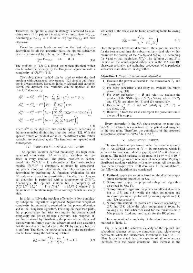
Therefore, the optimal allocation strategy is achieved by allo-cating each 〈i, j〉 pair to the relay which maximizes Wm,i,j .Accordingly, ψm,i,j = 1 if m = argmax
mWm,i,j and zero
otherwise.
Once the power levels as well as the best relay aredetermined for all the subcarrier pairs, the optimal subcarrierpairs is determined by solving the following problem
maxθi,j
Wm,i,j s.t. (C1) (15)
The problem in (15) is a linear assignment problem whichcan be solved, efficiently, by the Hungarian algorithm with acomplexity of O(N3) [11].
The sub-gradient method can be used to solve the dualproblem with guaranteed convergence [12] since a dual func-tion is always convex. Based on initially selected dual variablesvector, the different dual variables can be updated at the(i+ 1)th iteration by
λ(i+1)Tk
= λ(i)Tk
− δ(i)(Pk −
N∑i=1
M∑m=1
P ∗mki
); ∀k ∈ {1, 2}
λ(i+1)Rm
= λ(i)Rm
− δ(i)
(PR −
N∑j=1
P ∗mRj
); ∀m
λ(i+1)I1
= λ(i)I1
− δ(i)(Ith −
(N∑i=1
M∑m=1
(Ωm1ip
∗m1i +Ωm
2ip∗m2i )
))
λ(i+1)I2
= λ(i)I2
− δ(i)
(Ith −
(M∑
m=1
N∑j=1
ΩmRjp
∗mRj
))(16)
where δ(i) is the step size that can be updated according tothe nonsummable diminishing step size policy [12]. With theupdated values of the dual variables, the different optimizationvariables are evaluated again. The iterations are repeated untilconvergence.
IV. PROPOSED SUBOPTIMAL ALGORITHM
The optimal solution derived previously has high com-putational complexity. (M + 4) dual variables are up-dated in every iteration. The primal problem is decom-posed into N(NM + 1) sub-problems. Each sub-problemrequires O(NLN−1) complexity to obtain its correspond-ing power allocation. Afterwards, the relay assignment isdetermined by performing M functions evaluation for theN ! subcarrier matching possibilities. Finally, the Hungar-ian algorithm is performed with a complexity of O(N3).Accordingly, the optimal solution has a complexity ofO (
T(N3(MLN−1 + 1) +N2LL−1 +MN !
))where T is
the number of iterations required to converge which is usuallyhigh.
In order to solve the problem efficiently, a low complex-ity suboptimal algorithm is proposed. Significant weight ofcomplexity is, essentially, required in the power allocationand in the Hungarian algorithm. Focusing on these two parts,the proposed algorithm tries to simplify the computationalcomplexity and get an efficient algorithm. The proposed al-gorithm is started by distributing the power of the relays andtransceivers uniformly over the subcarriers and also assumingthat the interference introduced to the PU by every subcarrieris uniform. Therefore, the power allocation in the transceiverscan be found using the following relation
pmki = min
(PkN,IthΩikN
); k = 1, 2 (17)
while that of the relays can be found according to the followingformula
pmRj = min
(PRN,
Ith
ΩjRmN
)(18)
Once the power levels are determined, the algorithm searchesfor the best second time slot subcarrier, i.e. j, and relay m thatmaximize the product of the SNR1 and SNR2, i.e. searchingfor j and m that maximizes Rm,i,jAF . By defining A and B toinclude all the non-assigned subcarriers in the MA and BCphases,respectively, the assigning procedures of a particularsubcarrier i are detailed in Algorithm 1.
Algorithm 1 Proposed Sub-optimal Algorithm
1) Evaluate the power allocated to the transceivers T1 andT2 using (17).
2) For every subcarrier j and relay m, evaluate the relayspower using (18).
3) For every subcarrier j ∈ B and relay m, evaluate theproduct of the SNRs Q = SNR1 ∗ SNR2 where SNR1
and SNR2 are given by (4) and (5) respectively.4) Determine j∗ ∈ B and m∗ satisfying (J∗,m∗) =
argmaxj,mQ.5) Remove j∗ from the set B and repeat the procedures until
the set A is empty.
Every subcarrier in the MA phase requires no more than2(NM + 1) function evaluations to be paired and assignedto the best relay. Therefore, the complexity of the proposedsub-optimal scheme is O(2N2M + 2N2).
V. SIMULATION RESULTS
The simulations are performed under the scenario given inFig. 1. An OFDM system of N = 16 subcarriers, which issufficient to have a zero duality gap [9] and M = 6 relays areassumed. The noise variance is assumed to be σ2 = 5× 10⁻⁶
and the channel gains are outcomes of independent Rayleighdistributed random variables with unity mean. All the resultshave been averaged over 1000 iterations. In the simulations,the following algorithms are considered
1) Optimal: apply the solution based on the dual decompo-sition technique presented in Sec. III.
2) Suboptimal: apply the proposed suboptimal algorithmdescribed in Sec. IV.
3) Suboptimal+Hungarian: the power are allocated accord-ing to (17) and (18) while the relay assignment andsubcarrier paring are performed by solving equations (14)and (15) respectively.
4) Suboptimal+Fixed: the power are allocated according to(17) and (18) while the relay assignment is found bysolving (14). The subcarrier used for the transmission inMA phase is fixed and used again for the BC phase.
The computational complexity of the algorithms are sum-marized in Table. I.
Fig. 2 depicts the achieved capacity of the optimal andsuboptimal schemes versus the transceivers and relays powerconstraints when the interference threshold is fixed to −10dBm. It can be noted that the capacity of all schemes areincreased with the power constraint. This increase in the
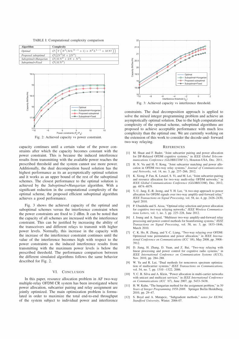
TABLE I: Computational complexity comparison
Algorithm ComplexityOptimal O
(T
(N3(MLN−1 + 1) +N2LL−1 +MN !
))
Proposed suboptimal O(2N2M + 2N2)
Suboptimal+Hungarian O(MN2 + 2N +N3)
Suboptimal+Fixed O(MN2)
−10 −5 0 5 10 1517
17.5
18
18.5
19
19.5
Power constraints (Pk=PR)
Cap
acity
Bit/
Sec
/Hz
OptimalSuboptimal+HungarianProposed suboptimalSuboptimal+Fixed
Fig. 2: Achieved capacity vs power constraint.
capacity continues until a certain value of the power con-straints after which the capacity becomes constant with thepower constraint. This is because the induced interferenceresults from transmitting with the available power reaches theprescribed threshold and the system cannot use more power.Additionally, the dual decomposition based solution has thehighest performance as its an asymptotically optimal solutionand it works as an upper bound of the rest of the suboptimalschemes. The closest performance to the optimal solution isachieved by the Suboptimal+Hungarian algorithm. With asignificant reduction in the computational complexity of theoptimal scheme, the proposed efficient suboptimal algorithmachieves a good performance.
Fig. 3 shows the achieved capacity of the optimal andsuboptimal schemes versus the interference constraint whenthe power constraints are fixed to 2 dBm. It can be noted thatthe capacity of all schemes are increased with the interferenceconstraint. This can be justified by increasing the ability ofthe transceivers and different relays to transmit with higherpower levels. Normally, this increase in the capacity withthe increase of the interference constraint continues until thevalue of the interference becomes high with respect to thepower constraints as the induced interference results fromtransmitting with the maximum power levels is below theprescribed threshold. The performance comparison betweenthe different simulated algorithms follows the same behaviordescribed for Fig. 2.
VI. CONCLUSION
In this paper, resource allocation problem in AF two-waymultiple-relay OFDM CR system has been investigated wherepower allocation, subcarrier pairing and relay assignment arejointly optimized. The main optimization problem is formu-lated in order to maximize the total end-to-end throughputof the system subject to individual power and interference
−10 −8 −6 −4 −2 0 218
18.5
19
19.5
20
20.5
21
21.5
22
Interference threshold (Ith)
Cap
acity
Bit/
Sec
/Hz
OptimalSuboptimal+HungarianProposed suboptimalSuboptimal+Fixed
Fig. 3: Achieved capacity vs interference threshold.
constraints. The dual decomposition approach is applied tosolve the mixed integer programming problem and achieve anasymptotically optimal solution. Due to the high computationalcomplexity of the optimal scheme, suboptimal algorithms areproposed to achieve acceptable performance with much lesscomplexity than the optimal one. We are currently working onthe extension of this work to consider the decode-and- forwardtwo-way relaying.
REFERENCES
[1] M. Shaat and F. Bader, “Joint subcarrier pairing and power allocationfor DF-Relayed OFDM cognitive systems,” in IEEE Global Telecom-munications Conference (GLOBECOM’11), Houston-USA, Dec. 2011.
[2] H. N. Vu and H.-Y. Kong, “Joint subcarrier matching and power allo-cation in OFDM two-way relay systems,” Journal of Communicationsand Networks, vol. 14, no. 3, pp. 257–266, 2012.
[3] K. Xiong, P. Fan, K. Letaief, S. Yi, and M. Lei, “Joint subcarrier-pairingand resource allocation for two-way multi-relay OFDM networks,” inIEEE Global Communications Conference (GLOBECOM), Dec. 2012,pp. 4874–4879.
[4] Y.-U. Jang, E.-R. Jeong, and Y. H. Lee, “A two-step approach to powerallocation for OFDM signals over two-way amplify-and-forward relay,”IEEE Transactions on Signal Processing, vol. 58, no. 4, pp. 2426–2430,April 2010.
[5] P. Ubaidulla and S. Aissa, “Optimal relay selection and power allocationfor cognitive two-way relaying networks,” IEEE Wireless Communica-tions Letters, vol. 1, no. 3, pp. 225–228, June 2012.
[6] J. Joung and A. Sayed, “Multiuser two-way amplify-and-forward relayprocessing and power control methods for beamforming systems,” IEEETransactions on Signal Processing, vol. 58, no. 3, pp. 1833–1846,March 2010.
[7] C. K. Ho, R. Zhang, and Y.-C. Liang, “Two-way relaying over OFDM:Optimized tone permutation and power allocation,” in IEEE Interna-tional Conference on Communications (ICC ’08), May 2008, pp. 3908–3912.
[8] D. Jiang, H. Zhang, D. Yuan, and Z. Bai, “Two-way relaying withlinear processing and power control for cognitive radio systems,” inIEEE International Conference on Communication Systems (ICCS),Nov. 2010, pp. 284–288.
[9] W. Yu and R. Lui, “Dual methods for nonconvex spectrum optimiza-tion of multicarrier systems,” IEEE Transactions on Communications,vol. 54, no. 7, pp. 1310 –1322, 2006.
[10] Y. C. B. Silva and A. Klein, “Power allocation in multi-carrier networkswith unicast and multicast services,” in IEEE International Conferenceon Communications (ICC ’07), June 2007, pp. 5433–5438.
[11] H. W. Kuhn, “The hungarian method for the assignment problem,” in 50Years of Integer Programming 1958-2008. Springer Berlin Heidelberg,2010, pp. 29–47.
[12] S. Boyd and A. Mutapcic, “Subgradient methods,” notes for EE364,Standford University, Winter. 2006-07.


![1 Hierarchic Power Allocation for Spectrum Sharing in OFDM ... · PDF filearXiv:1211.5857v1 [cs.GT] 26 Nov 2012 1 Hierarchic Power Allocation for Spectrum Sharing in OFDM-Based Cognitive](https://img.pdfslide.us/doc/110x75/5a78f3717f8b9a9d218c0c16/1-hierarchic-power-allocation-for-spectrum-sharing-in-ofdm-12115857v1-csgt.jpg)