Embed Size (px)
Citation preview
Resistance to the ballistic impact of doped zirconia
L. Gómez1 & E. Ayllon2 1Dpto. Propulsión, CITEFA, Argentina 2Dpto. CyT Materiales, CITEFA, Argentina
Abstract
In the 1950s, with the appearance of oxide ceramics (Al203, ZrO2, BeO, MgO), ceramic materials started to arouse researchers’ interest. In 1975 Garvie and et al. originated a new family of ceramics based on the addition of zirconium oxide. In this work the mechanical properties and the penetration of a ballistic impact zirconia and alumina were studied from the tiles obtained by the sinterization of alumina and zirconia partially stabilized with Y2O3 (Y-PSZ). Several compositions were processed, always predominating, in volume, a matrix of alumina. Beside impact experiences, mechanical properties were also evaluated. The outcomes were analysed, comparing them against alumina formulae without the addition of zirconia. Keywords: zirconia, alumina, mechanical properties, dynamic charges.
1 Introduction
1.1 Introduction to ceramic materials
Ceramic materials have two important characteristics: they are generally harder, more resistant and lighter than metals and are capable of keeping a high resistance to deformation at high temperatures. However, the potential applications of ceramic materials such as alumina are conditioned by their fragility, which brings about sudden catastrophic fractures and a low resistance to thermal shock; which is why some authors have suggested the use of ZrO2 as a strengthening material [1]. For the ZrO2 to act as strengthening element it must appear in its tetragonal crystallographic structure since it has been documented
© 2008 WIT PressWIT Transactions on the Built Environment, Vol 98, www.witpress.com, ISSN 1743-3509 (on-line)
Structures Under Shock and Impact X 283
doi:10.2495/SU080281
that the mechanism through which ZrO2 strengthens the ceramic matrix is that one of the transformations is of ZrO2-tetragonal to ZrO2-monoclinic when the material is submitted to strains. The retention of the ZrO2-tetragonal is not simple at environmental temperatures because this is a steady phase at temperatures over 1200°C, the monoclinic shape is the one that persists at low temperatures. Several authors [2–4] have suggested the use of additives as stabilizers of the ZrO2-tetragonal to environmental temperatures within which we have the following: CaO, MgO, CeO and Y2O3. The transformation ZrO2-t to ZrO2-m is martensitical [5] and is accompanied by a volume increase of around 6% [6,7]. These compounds are known as FSZ “Fully Stabilized Zirconia”. Nevertheless, the material of highest technological importance is the PSZ “Partially Stabilized Zirconia” with 9% molar of Mg or 3–6% molar of Y.
1.2 The system ZrO – Y2O3
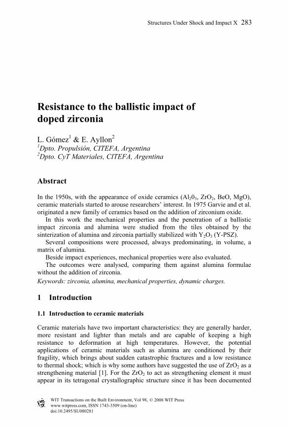
The diagram of the phases in figure 1 proposed by Scott [8,9] shows that the regions of solid solution of the tetragonal and monoclinic phases are conformed from 1200C to a slightly smaller value of 600C, according to the amount of stabilizing.
Figure 1: Diagram of phases of Y2O3 –ZrO2.
In this case, FSZ goes to values bigger than 12% molar (the entire phase is cubic) and PSZ takes place between 2–12% molar, with the monoclinic and cubic phases coexisting.
© 2008 WIT PressWIT Transactions on the Built Environment, Vol 98, www.witpress.com, ISSN 1743-3509 (on-line)
284 Structures Under Shock and Impact X
It is said that PSZ ceramics “self-repair” since they prevent the propagation of micro cracks because of a transformation of tetragonal phases to monoclinic which, when increasing the volume, closes the crack and stops it from propagating. This is a general mechanism known as increase of the tenacity by phase transformation [10,11].
1.3 Strengthening mechanisms in zirconia ceramic materials
In ceramic materials, plastified areas are not formed in front of the cracks as in the case of metals, as there is no a noticeable movement of dislocations [12,13], at least at environmental temperatures. The fracture at environmental temperatures will take place by cleavage, once the necessary stress is reached for the propagation of defects. Nevertheless, there are several mechanisms that increase the tenacity of these materials, and create a fracture whenever the tension is strong enough for the fracture process around the tip of the crack. It is hazardous because there are numerous works devoted to the study of this subject [12,14–16], each one with its own way of classifying mechanisms and specifying the way in which they contribute to the tenacity increase. Besides, some mechanisms can operate simultaneously; therefore it is difficult to separate the effect each one produces. For zirconia alloys there are three main mechanisms [17–19]: Tenacity increase by transformation Tenacity increase by micro fissures induced by the transformation Tenacity increase by diverting the trajectory of the fissure.
1.4 Behaviour of materials exposed to a ballistic impact
The behaviour of metals and ceramics is completely different when exposed to ballistic impact. Ceramic materials:
- Do not have a plastic deformation in front of an impact, keeping their elasticity until the moment of fracture.
- Have a very high fusion point, therefore they do not suffer a localized effect of temperature on impact. They do not suffer deformation and retain their properties.
- Are fractured by the effect of the shock and at the same time produce a similar effect by erosion on the projectile, causing it (or what is left of it) to stop.
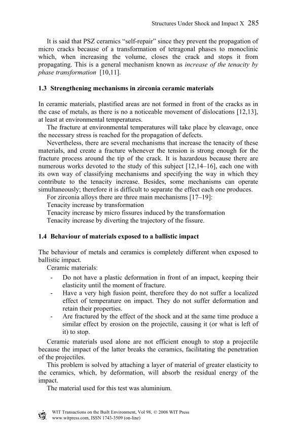
Ceramic materials used alone are not efficient enough to stop a projectile because the impact of the latter breaks the ceramics, facilitating the penetration of the projectiles. This problem is solved by attaching a layer of material of greater elasticity to the ceramics, which, by deformation, will absorb the residual energy of the impact. The material used for this test was aluminium.
© 2008 WIT PressWIT Transactions on the Built Environment, Vol 98, www.witpress.com, ISSN 1743-3509 (on-line)
Structures Under Shock and Impact X 285
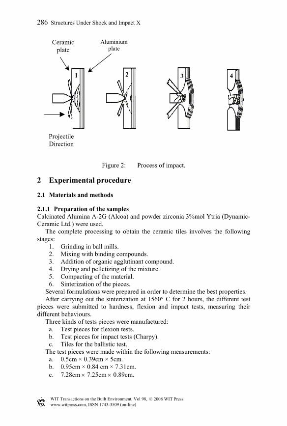
Figure 2: Process of impact.
2 Experimental procedure
2.1 Materials and methods
2.1.1 Preparation of the samples Calcinated Alumina A-2G (Alcoa) and powder zirconia 3%mol Ytria (Dynamic-Ceramic Ltd.) were used. The complete processing to obtain the ceramic tiles involves the following stages:
1. Grinding in ball mills. 2. Mixing with binding compounds. 3. Addition of organic agglutinant compound. 4. Drying and pelletizing of the mixture. 5. Compacting of the material. 6. Sinterization of the pieces.
Several formulations were prepared in order to determine the best properties. After carrying out the sinterization at 1560° C for 2 hours, the different test pieces were submitted to hardness, flexion and impact tests, measuring their different behaviours. Three kinds of tests pieces were manufactured:
a. Test pieces for flexion tests. b. Test pieces for impact tests (Charpy). c. Tiles for the ballistic test.
The test pieces were made within the following measurements: a. 0.5cm × 0.39cm × 5cm. b. 0.95cm × 0.84 cm × 7.31cm. c. 7.28cm × 7.25cm × 0.89cm.
Aluminium plate
Ceramic plate
Projectile Direction
1 2 3 4
© 2008 WIT PressWIT Transactions on the Built Environment, Vol 98, www.witpress.com, ISSN 1743-3509 (on-line)
286 Structures Under Shock and Impact X
2.2 Mechanical tests
2.2.1 Hardness tests Hardness tests were performed on all the pieces with a Galileo hardmeter and the results were expressed in Rockwell “C” values.
2.2.2 Flexion tests Flexion tests, known as a measurement of the module in three points, were performed according to the MIL-STD 1942ª norm.
Resistance to flexion = 3F·L/(2wh2) (1) The elastic module is obtained indirectly taking into account the slope of the origin of the charge-moving record (P/X), through the expression of the requested girder in a ratio flexion of three points, according to the following relation:
Module in flexion = L3 P/(4wh3X) (2)
The machine used for this test was an MTS 810 Universal. The charge measure applied was performed through a charge cell of 5000N within the rank of 2000N and at a constant speed of 0.5mm/min.
2.2.3 Resilience tests The resilience tests were carried out on a Charpy pendulum, using a Charpy Impact Testing Machine JIS4J (4 Joules), which is a low capacity machine used for ceramic and plastic (the norm is ASTM D 256-92), with the aim of obtaining the so called CIV: Charpy Impact Value.
2.2.4 Impact test The international norm NIJ (National Institute of Justice) Standard 0108.01 was chosen for the impact tests. The distance between the cannon mouth and the target was 15 metres and the speed of the projectile ranged between 823–853 m/s. These tests were carried out by using FAL 7.62 x 51mm ammunition and all the tests proved successful.
3 Results
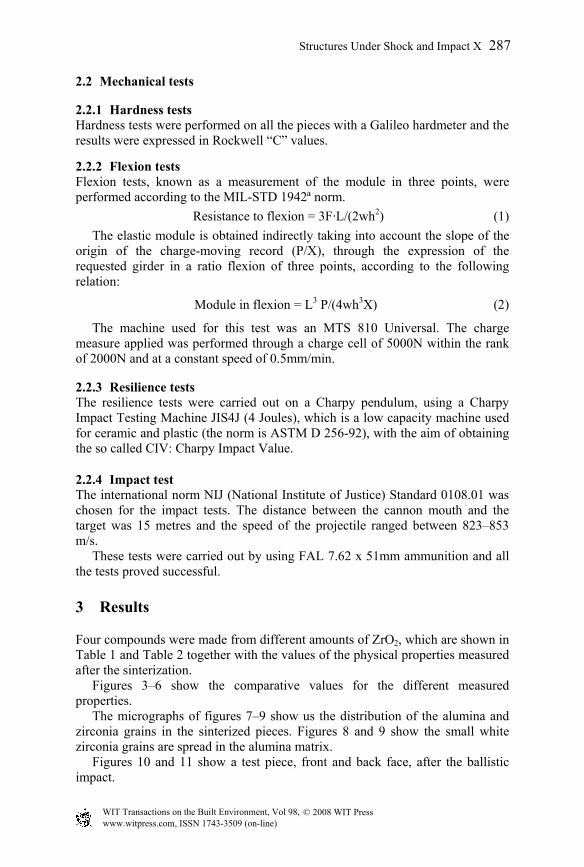
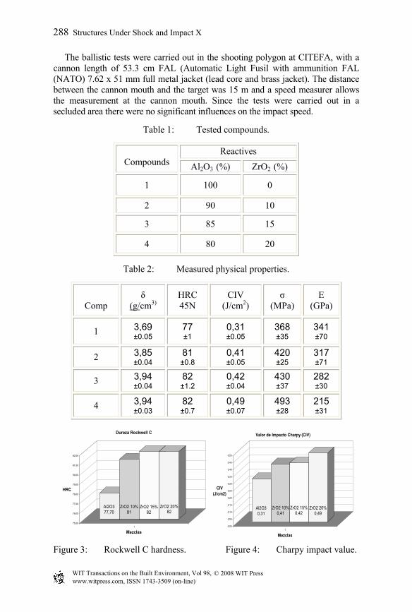
Four compounds were made from different amounts of ZrO2, which are shown in Table 1 and Table 2 together with the values of the physical properties measured after the sinterization. Figures 3–6 show the comparative values for the different measured properties. The micrographs of figures 7–9 show us the distribution of the alumina and zirconia grains in the sinterized pieces. Figures 8 and 9 show the small white zirconia grains are spread in the alumina matrix. Figures 10 and 11 show a test piece, front and back face, after the ballistic impact.
© 2008 WIT PressWIT Transactions on the Built Environment, Vol 98, www.witpress.com, ISSN 1743-3509 (on-line)
Structures Under Shock and Impact X 287
The ballistic tests were carried out in the shooting polygon at CITEFA, with a cannon length of 53.3 cm FAL (Automatic Light Fusil with ammunition FAL (NATO) 7.62 x 51 mm full metal jacket (lead core and brass jacket). The distance between the cannon mouth and the target was 15 m and a speed measurer allows the measurement at the cannon mouth. Since the tests were carried out in a secluded area there were no significant influences on the impact speed.
Table 1: Tested compounds.
Reactives Compounds Al2O3 (%) ZrO2 (%)
1 100 0
2 90 10
3 85 15
4 80 20
Table 2: Measured physical properties.
Figure 3: Rockwell C hardness. Figure 4: Charpy impact value.
Comp
δ (g/cm3)
HRC 45N
CIV (J/cm2)
σ (MPa)
E (GPa)
1 3,69 ±0.05
77 ±1
0,31 ±0.05
368 ±35
341 ±70
2 3,85 ±0.04
81 ±0.8
0,41 ±0.05
420 ±25
317 ±71
3 3,94 ±0.04
82 ±1.2
0,42 ±0.04
430 ±37
282 ±30
4 3,94 ±0.03
82 ±0.7
0,49 ±0.07
493 ±28
215 ±31
Al2O377,70
ZrO2 10%81
ZrO2 15%82
ZrO2 20%82
75,00
76,00
77,00
78,00
79,00
80,00
81,00
82,00
HRC
1
Mezclas
Dureza Rockwell C
Al2O30,31
ZrO2 10%0,41
ZrO2 15%0,42
ZrO2 20%0,49
0,00
0,05
0,10
0,15
0,20
0,25
0,30
0,35
0,40
0,45
0,50
CIV (J/cm2)
1
Mezclas
Valor de Impacto Charpy (CIV)
© 2008 WIT PressWIT Transactions on the Built Environment, Vol 98, www.witpress.com, ISSN 1743-3509 (on-line)
288 Structures Under Shock and Impact X
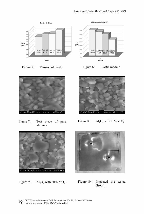
Figure 5: Tension of break. Figure 6: Elastic module.
Figure 7: Test piece of pure alumina.
Figure 8: Al2O3 with 10% ZrO2.
Figure 9: Al2O3 with 20% ZrO2. Figure 10: Impacted tile tested (front).
Al2O3367,91
ZrO2 10%419,55
ZrO2 15%430,05
ZrO2 20%493,39
0,00
50,00
100,00
150,00
200,00
250,00
300,00
350,00
400,00
450,00
500,00
Sigma (MPa)
1
Mezcla
Tensión de Rotura
Al2O3340,79
ZrO2 10%317,21
ZrO2 15%282,45
ZrO2 20%214,99
0,00
50,00
100,00
150,00
200,00
250,00
300,00
350,00
E (GPa)
1
Mezcla
Módulo de elasticidad "E"
© 2008 WIT PressWIT Transactions on the Built Environment, Vol 98, www.witpress.com, ISSN 1743-3509 (on-line)
Structures Under Shock and Impact X 289
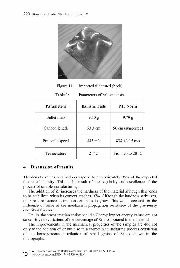
Figure 11: Impacted tile tested (back).
Table 3: Parameters of ballistic tests.
Parameters Ballistic Tests NIJ Norm
Bullet mass 9.30 g 9.70 g
Cannon length 53.3 cm 56 cm (suggested)
Projectile speed 845 m/s 838 +/- 15 m/s
Temperature 21° C From 20 to 28° C
4 Discussion of results
The density values obtained correspond to approximately 95% of the expected theoretical density. This is the result of the regularity and excellence of the process of sample manufacturing. The addition of Zr increases the hardness of the material although this tends to be stabilized when its content reaches 10%. Although the hardness stabilizes, the stress resistance to traction continues to grow. This would account for the influence of some of the mechanism propagation resistance of the previously described fissures. Unlike the stress traction resistance, the Charpy impact energy values are not so sensitive to variations of the percentage of Zr incorporated in the material. The improvements in the mechanical properties of the samples are due not only to the addition of Zr but also to a correct manufacturing process consisting of the homogeneous distribution of small grains of Zr as shown in the micrographs.
© 2008 WIT PressWIT Transactions on the Built Environment, Vol 98, www.witpress.com, ISSN 1743-3509 (on-line)
290 Structures Under Shock and Impact X
In the ballistic tests, preliminary results show that the deformation in the supporting aluminium plate that acts as a backup to the tiles was considerably smaller in the those which contained zirconia than in those of pure alumina. This shows the activity of the strengthening mechanisms produced by the addition of Zr, even for high speed deformation.
5 Conclusions
The addition of zirconia Y-PSZ to the mixture of alumina seems to have considerably improved the properties of the sinterized material. The density and microstructures obtained demonstrated a uniform and adequate manufacturing process. An important increase in the values of hardness, Charpy impact energy and breaking tension can be observed. The results were highly satisfactory. For the next research, the same targets should be used with a perforating type projectile or, with the same projectile, using thinner targets taking advantage of the apparent tenacity increase in order to relieve weight.
References
[1] R.C. Garvie, R.H. Hannink and R.T. Pascoe, Nature, Vol 258, 1975, p 703. [2] G.M. Wolten. J. Am. Ceram. Soc., 46 (9) 418 (1963). [3] O.K. Bansal y A.H. Heuer, Acta Metalí., 20 1281–1289 (1972). [4] O.K. Bansal y Aif. Heuer, Acta MetaIl., 22 409–417 (1974). [5] C.M. Wayman, “Martensitic transformations”. Science and technology of
zirconia. Advances in ceramics. Vol.3, PP 64 Ed. A.H. Heuer and L.W. Hobbs. The Amer. Cer. Soc. Inc. Columbus, Ohio, (1981).
[6] O. Ruff and F. Ebert, Z. Anorg. Allg. Chem., 180, 1, 19(1929). [7] O. Ruff, F. Ebert y E. Stephen, Z. Amorg. Allg. Chem. 180 (1) 215 (1929). [8] H.G. Scott, J. Mater. Sci., 10 9 1527–35 (1975). [9] H.G. Scott, J. Mater. Sci.,12 2 311–316 (1977). [10] N. Claussen et al, Ceramics in Advanced Energy Technology, D. Reidel
Publ. Co, The Netherlands, 51–86 (1984). [11] Mecking et al, J. Am. Ceram. Soc.. 65 5 242–46 (1982). [12] B.R. Lawn, A.G. Evans and D.B. Marshall, J. Am. Ceram. Soc. 63 (9-10)
574–81(1980). [13] Kingery, W. D., Bowen, U. K. y Uhlmann, D. R., “Introduction to
Ceramics”. Ed. John Wiley and Son, NY., USA, 1986. [14] A.G. Evans, Advanced in Ceramics, Vol 12. Science and Technology of
Zirconia II pp 195, Edit. by N. Claussen, M. Ruhle and A.H. Heuer. Am. Ceram. Soc. Columbus. OH (1984).
[15] Y.W. Mai and BR. Law, en Hugging, A.F., Am. Rey. Mat. Sci., 16 415–39 (1986).
[16] R.W. Steinibrech and Schmenkel, Y Am. Ceram. Soc.,71 5 C-271–77 (1988).
© 2008 WIT PressWIT Transactions on the Built Environment, Vol 98, www.witpress.com, ISSN 1743-3509 (on-line)
Structures Under Shock and Impact X 291
[17] R. Stevens, Engineering Properties of Zirconia. Engineering Materials Handbook V.4: Ceramics and Glasses, PP 775–786, ASTM International Handbook Committee. N.Y. (1991).
[18] N. Claussen, J. Am. Ceram. Soc., Vol 59, p 49 (1976). [19] A.G. Evans and K.T. Faber, J. Am. Ceram. Soc., 67 4 255–260 (1984).
© 2008 WIT PressWIT Transactions on the Built Environment, Vol 98, www.witpress.com, ISSN 1743-3509 (on-line)
292 Structures Under Shock and Impact X