Embed Size (px)
Citation preview

University of Plymouth
PEARL https://pearl.plymouth.ac.uk
Faculty of Science and Engineering School of Engineering, Computing and Mathematics
2018-12
Residual crashworthiness of CFRP
structures with pre-impact damage An
experimental and numerical study
Chen, D
http://hdl.handle.net/10026.1/12236
10.1016/j.ijmecsci.2018.08.030
International Journal of Mechanical Sciences
Elsevier
All content in PEARL is protected by copyright law. Author manuscripts are made available in accordance with
publisher policies. Please cite only the published version using the details provided on the item record or
document. In the absence of an open licence (e.g. Creative Commons), permissions for further reuse of content
should be sought from the publisher or author.
1
Residual crashworthiness of CFRP structures with pre-impact damage
– An experimental and numerical study
Dongdong Chen1, Guangyong Sun1, 2,*, Maozhou Meng3, Guangyao Li1, Qing Li2
11State Key Laboratory of Advanced Design and Manufacture for Vehicle Body,
Hunan University, Changsha, 410082, China
2School of Aerospace, Mechanical and Mechatronic Engineering, The University of
Sydney, Sydney, NSW 2006, Australia
3School of Marine Science and Engineering, Plymouth University, Plymouth, United
Kingdom
Abstract
This study investigated the effect of transverse pre-impact damage on the load bearing
capacity and failure behavior of square carbon fiber reinforced plastic (CFRP) tubes for axial
crushing. The CFRP tubes were impacted transversely in different levels of impact energies to
generate initial damage, and then the specimens were further crushed axially to evaluate the
relation between transverse impact energies/positions and the residual axial crashworthiness.
A finite element (FE) model was also developed to simulate the complex damage behavior of
the CFRP tubes under these two different loading processes, based upon the continuum
damage model (CDM) with user-defined material subroutine in Abaqus. A combined failure
mode was observed in the transverse pre-impact tests, in which delamination was combined
with partial or complete fiber breakage when increasing the impact energy from 10 J to 30 J.
In the axial compression tests, two typical failure modes with circumferential fracture near the
pre-impact position were identified for the damaged tubes, exhibiting significant difference
from the progressive folding failure seen in undamaged tubes. Further, the damaged tubes
yielded up to 38%, 58.5% and 58.3% reduction in terms of the peak load, mean load and
energy absorption respectively in comparison with the specimens without pre-impact
damages. It is also found that the residual crushing capacity decreased with increase in the
transverse pre-impact energy; nevertheless the residual axial crushing properties were
insensitive to single or double impacts on different circumferential positions. The failure
modes of fiber breakage, delamination and matrix crack were investigated in detail by using
the FE analysis.Keywords: Residual crushing capacity; CFRP tube; Pre-impact damage;
Crashworthiness
1* Corresponding Author: Tel: +86-13786196408; Email: [email protected].

2
1. Introduction
Higher requirements of fuel efficiency and structural safety are in strong demand with
intensifying socioeconomic legislation and industrial standard [1-3]. In general, these two
aspects often conflict with each other [4]. One way to tackle this challenge is to replace
traditional heavy metals with light-weight materials while remaining or even enhancing the
structural performances. In this regard, carbon fiber reinforced plastic (CFRP) composites
have been exhibiting significant potential thanks to their extraordinary capacity of weight to
specific stiffness, strength and energy absorption [5].
To understand crash behavior of CFRP structures, substantial experimental studies have
been conducted on crashworthiness of various tubal components. For example, Mamalis et al.
[6, 7] investigated the different collapse modes of square CFRP composite tubes subjected to
static and dynamic axial crashes, and they found that only the progressive crushing mode
absorbed the highest energy. They also identified that the peak crushing load increased with
increase of wall thickness and fiber volume content. Jia et al. [8] investigated the quasi-static
crushing behavior of filament wound CFRP cylinder with different geometric parameters,
winding angles and pre-crack angles. They concluded that the evolution process of failure
mostly depended on the pre-crack angle which would cause the crack initiation. Siromani et
al. [9] studied three typical failure trigger modes to identify their effects on initial peak load
and specific energy absorption (SEA); and they showed that combing a chamfered tube with
an inward-folding crush-cap yielded the lowest initial peak load and the highest SEA. Liu et
al. [5] analyzed the effects of wall thickness and lengths of the double hat shaped CFRP
tubes; they identified two distinctive failure modes through the dynamic tests, which differed
with a typical mode of continuous splaying fronds in quasi-static tests. They also reported that
increasing impact velocity would increase the peak load but decrease the energy absorption
(EA) and specific energy absorption (SEA). Meredith et al. [10] explored the effects of
manufacture processes (e.g. vacuum assisted oven cure and autoclave cure) on crash
performance of CFRP cones through dynamic impact tests, in which performance versus cost
analysis was conducted, revealing enormous potential for cost reduction of prepreg carbon
fiber epoxy cones through use of heavier areal weight fabrics with fewer plies as well as
through use of oven cured prepreg.
Numerical modeling represented by finite element method has gained growing
popularity for its advantages in simulating mechanical behaviors of composite tubes in detail.

3
For example, McGregor et al [11] adopted the continuum damage mechanics model (CDM) to
predict axial impact of two-ply and four-ply square tubes with and without an external plug
initiator using LS-DYNA; and good agreement was obtained in terms of the failure
characteristics and energy absorption. Zhu et al. [12] proposed two different numerical
models, namely multi-layer stacked model and single-layer shell model, to simulate the
crushing process of CFRP structures; and they found that the multi-layer stacking model
exhibited a better capability of predicting the main failure modes and crashworthiness of the
CFRP structures. Obradovic et al. [3] carried out the experimental, analytical and numerical
studies on the crash analysis of composite structures under frontal impact, demonstrating the
critical importance of selecting failure criteria for predicting brittle collapse. In literature,
some typical composite damage models, e.g. MAT58 and MAT54 in LS-DYNA, were
validated and have proven to be effective for simulating the inter-ply delamination under axial
crushing [13, 14]. Two different finite element (FE) models, namely stacked shell model and
crushing zone model, were developed for predicting the energy absorption in the crushing
process [15]. However, these abovementioned FE models have not model complex failure
mechanism of CFRP tubes for predicting crushing process and energy absorption.
It is well known that CFRP composite structures are very sensitive to dynamic loading;
and even a minor, invisible damage could cause noticeable reduction in the strength and
stiffness [16]. Therefore, it is crucial to evaluate the load-bearing capacity of composite
structures with any pre-existed damage at different levels. In literature, there have been some
studies available on evaluating the residual performance of CFRP structures with some pre-
generated holes, defects and/or damages. In this regard, Liu et al. [17] undertook an
experimental and numerical study on the load bearing behavior of square CFRP tubes with
open holes subjected to axial compression; the effects of hole sizes, shape and distribution on
the first peak force, failure modes and SEA were explored. It exhibited that the hole size had
the stronger effect on peak load and SEA than hole shape and distribution. Guades and
Aravinthan [18] conducted an experimental study on the residual properties of square
pultruded tubes made of E-glass fiber composites subjected to axial impact, in which the
coupons taken around the impacted area were tested with compressive, tensile and flexural
loadings. Their study revealed that the residual strength of the pre-impacted tubes degraded
with the pre-impact energy, number of impacts and mass of the impactor, whilst little effect
appeared on the residual modulus. Sebaey and Mahdi [19] studied the quasi-static transverse
crushing characteristics of glass/epoxy pipes by introducing impact damage. They found that
the peak load was reduced by 23% for top/bottom pre-impacted tube and 15% for the side
4
pre-impacted tube in comparison with those of the non-impacted ones, meaning that the
capacity of resisting crash was reduced due to the pre-impacted damage. With the increase in
the impact energy and impact numbers, such a reduction trend could be also seen in the peak
force and average crushing load.
In literature, most of the existing numerical studies on residual mechanical response of
composites have been focused on laminates [20-25]. For example, Wang et al. [20] developed
a FE model to simulate the low-velocity impact characteristics and predicted the residual
tensile strength, in which a progressive damage model with stress-based Hashin criteria was
used to model the fiber and matrix failures of the CFRP laminates under impact load. Abir et
al. [21] investigated the effects of impact damage on crushing performance of CFRP
laminates numerically, in which the continuum damage mechanics (CDM) model and
cohesive interface elements were adopted to characterize the fiber failure and inter-laminar
fracture behavior. Tan et al. [22] adopted a three-dimensional composite damage model to
simulate the fiber failure and delamination behavior under the so-called compression-after-
impact (CAI) test; and good agreement was obtained between the numerical and experimental
results in terms of force-displacement curves, damage contours and permanent indentation.
As for the composite laminates reinforced by unidirectional fibers, the cohesive connections
were introduced only in the areas between the plies with different fiber orientations for
reducing the computational cost [23]; and the simulated results showed fairly good accuracy
on modeling the complex failure phenomena during crushing after the initial impact tests.
The previous study indicated that the CFRP tubes are of sizeable advantages on
crashworthiness than aluminum counterparts under quasi-static axial loading [26]. There is a
great potential of replacing traditional metallic energy absorbers with CFRP structures
attributable to its high energy absorption and lightweight performance. Crash box, as one
important application for energy absorption, could be subjected to various impact loading
during its life cycle, such as tools dropping (assembling process) or collision from ground
pebbles (travel process), representing accumulative damage from different pre-impacts.
Unfortunately, only few studies have been available in literature for evaluating the residual
crushing behavior of composite tubes with pre-introduced damage. In this regard, Liu et al.
[17] investigated the damage mechanisms of perforated CFRP tubes under quasi-static
crushing. Their FE model was able to model the crack initiation, propagation and strain
distribution around the pre-perforated hole edges accurately. Deniz et al. [27] explored the
low-velocity crushing with pre-impacted damage in the [±55]3 filament-wound glass/epoxy
composite circular tubes. To the author’s best knowledge, nevertheless, there has been no
5
study available to explore the complex damage mechanism for the axial crash with pre-
impacted damage laterally. It remains to identify the residual axial crashworthiness for the
CFRP tubes with pre-impacted damage in the transverse direction.
This study aimed to provide an experimental and numerical investigation into the
residual load bearing capacity of the CFRP tubes with lateral pre-impacted damage. The
failure modes and force-displacement curves characterized by different impact energies were
analyzed, and then the damage mechanisms induced by different loading levels were
discussed based upon the optical observations on the fractured area. The effects of impact
parameters such as impact energy and impact position on the residual axial crushing
properties were investigated in detail. The study is expected to provide a guideline for
quantifying residual crashworthiness of CFRP tubes with pre-damage in a different direction.
2. Materials and experimental methods
2.1. Materials
Square CFRP tubes were fabricated from plain weave fabric carbon-epoxy pre-preg
(provided by Toray industries [12]) by using the bladder molding process. The tube walls
were constructed with 9 layers, having 1.98mm in thickness, 100mm in length and 60mm in
side width. The stacking sequence of piles was in a form of [0°/90°]. All the specimens were
prepared with the 45 chamfer of 1mm, as shown in Fig. 1(c).
2.2. Low-velocity pre-impact tests
The low-velocity pre-impact tests were performed using INSTRON 9350 drop weight
testing machine. A hemispherical impactor with 20 mm in diameter and m = 2.41 kg in mass
was chosen for the tests. Different incident impact energies can be generated by changing the
initial height of the impactor. A pressure of 500 N was applied on the fixtures to clamp the
CFRP tube during the impact test as shown in Fig. 1. Two support blocks (fit to the inner
dimension of the tube as 56 56 20 mm) were manufactured and placed in each end of the
CFRP tube to replicate the real assembly condition and avoid excessive deformation during
the crash tests.
Two pre-impact parameters, namely the impact position and impact energy, were
considered in this study. For each energy level, three repeats were performed and the results
were summarized in Table 1. A labelling system was used to facilitate the analysis and
comparison. For example, AC indicates that tubes were crashed axially without any pre-
impacted damage, which serves as the comparison (control) group. The effects of pre-impact

6
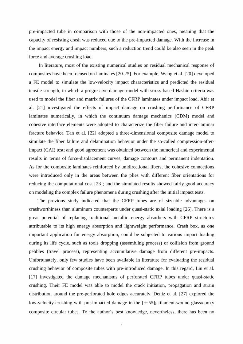
were investigated as per E1-P1, E2-P1 and E3-P1, meaning that the tubes were impacted at
the same impact position (P1 as shown in Fig. 2) but different pre-impact energies (E1/E2/E3,
representing 10/20/30 J to generate different levels of damage during the transverse pre-
impaction). The number of impacts and impact energy for E2-P2 and E2-P3 were the same,
i.e. 2 times, and each with the same level of 20 J separately; but at the different impact
locations, i.e. P2 and P3 as shown in Fig. 2. The impact position on the impacted face was the
same for every impact test, i.e. the same coordinate as the P1 cases but on the different faces.
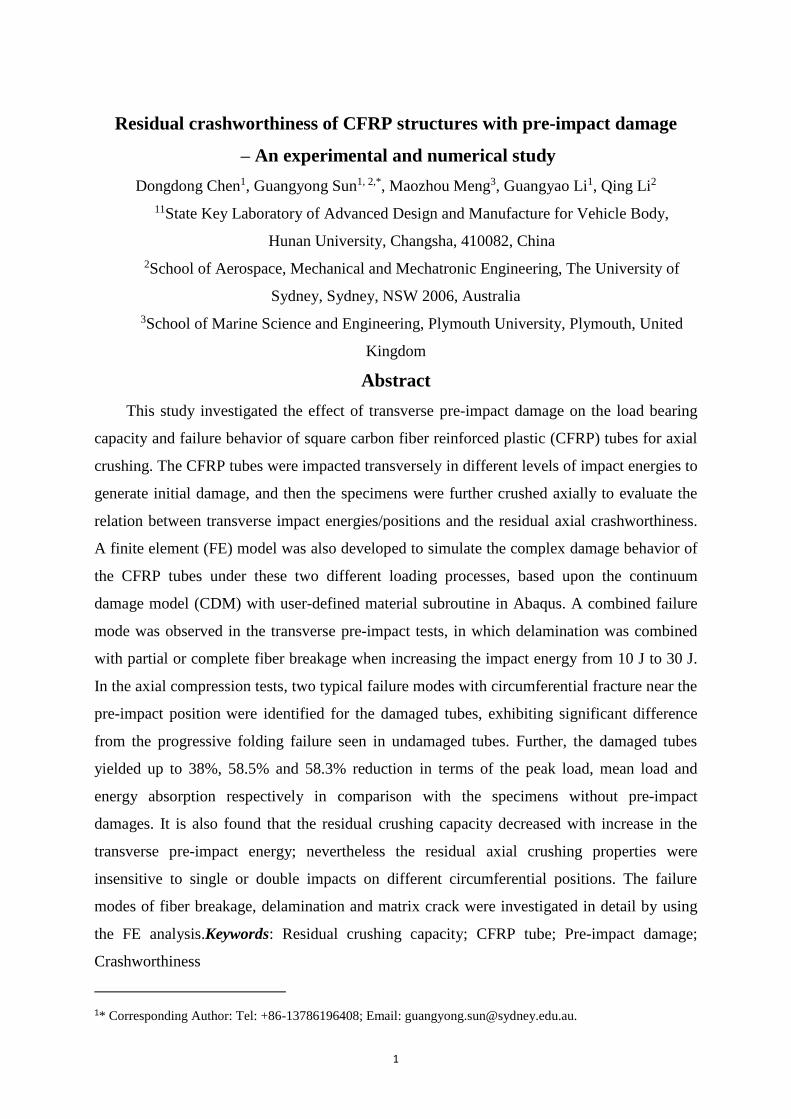
Fig. 1. Illustration of the low-velocity impact test system: (a) low-velocity test set-up, (b) enlarged view of
the clamp area, and (c) details for specimen and support blocks (unit: mm).
Fig. 2. Positions of the impacts in three cases (unit: mm, red X represents the impact point).
Table 1 Crashworthiness characteristics of the tested specimens.
Tube label
Impact After impact
Ei (J) Ea (J) Pmax
(kN)
Failure
mode
Pmax
(kN)
Pmean
(kN) Ea (kJ) CFE
AC-1 0.0 0.0 0.0 I 77.8 60.3 48.3 0.78
AC-2 0.0 0.0 0.0 I 86.9 58.8 47.1 0.68 AC-3 0.0 0.0 0.0 I 85.1 61.7 49.4 0.72
Average 0.0 0.0 0.0 83.2 60.3 48.3 0.72
7
S.D. 0.0 0.0 0.0 3.9 1.2 0.9 0.04
E1-P1-1 10.0 7.6 2.2 II 68.7 43.1 34.5 0.63
E1-P1-2 10.0 7.2 2.1 II 69.5 30.7 24.6 0.44
E1-P1-3 10.0 7.4 2.5 I 65.1 51.5 41.2 0.79
Average 10.0 7.4 2.3 67.8 41.8 33.4 0.62
S.D. 0.0 0.2 0.2 1.9 8.5 6.8 0.14
E2-P1-1 20.0 18.7 2.3 III 60.4 28.7 23.0 0.48
E2-P1-2 20.0 18.6 2.2 III 56.1 20.6 16.5 0.38
E2-P1-3 20.0 17.6 2.0 III 60.7 24.8 19.9 0.41
Average 20.0 18.3 2.1 59.0 24.7 19.8 0.42
S.D. 0.0 0.5 0.1 2.1 3.3 2.7 0.04
E3-P1-1 30.0 19.5 2.3 III 54.6 34.3 27.5 0.63
E3-P1-2 30.0 20.4 2.2 III 61.9 33.6 26.9 0.54
E3-P1-3 30.0 21.5 2.3 III 63.0 33.1 26.5 0.53
Average 30.0 20.5 2.3 59.8 33.7 27.0 0.56
S.D. 0.0 0.8 0.0 3.7 0.5 0.4 0.04
E2-P2-1 20.0 18.3 2.2 III 62.8 25.0 20.0 0.4
E2-P3-1 20.0 18.8 2.2 III 51.5 28.7 23.0 0.56
S.D. means the standard deviation.
2.3. Axial crush after transverse pre-impacts
Quasi-static axial crushing tests for the pre-impacted specimens were carried out in a
standard universal testing machine INSTRON 5985 with a load capacity of 150 kN. A
constant cross-head velocity of 4 mm/min was set throughout the test at the room
temperature. All the specimens were crushed up to 80% of their original length, i.e. 80mm.
The detailed deformation and failure process were recorded by a camera with the
displacement interval of 2 mm. For comparison, the tests with non-pre-impacted specimens
were also conducted.
A crashworthy structure should have excellent capacity of absorbing sufficient energy
with a low peak crushing force. In literature, four different indicators were often adopted to
evaluate the crashworthiness of structures [28]. The peak force (𝑃𝑚𝑎𝑥), which is the maximum
force value in the displacement-force curves recorded from the tests, should be as low as
possible to protect the occupants from fatal injuries [28]. The mean crushing force (𝑃𝑚𝑒𝑎𝑛)
was used to measure the energy absorption as:
𝑃𝑚𝑒𝑎𝑛 =1
𝐿∫
𝐿
0
𝑃𝑑𝑈 (1)
where 𝑃 and 𝑈 are the crush load and displacement, respectively; 𝐿 is the total displacement.
The crush force efficiency (𝐶𝐹𝐸) can be used to evaluate the variation of 𝑃𝑚𝑒𝑎𝑛 relative
to 𝑃𝑚𝑎𝑥, which should be close to 1 for the best possible force level,
𝐶𝐹𝐸 =𝑃𝑚𝑒𝑎𝑛
𝑃𝑚𝑎𝑥 (2)
The energy absorption (𝐸𝑎) is the energy dissipated during the crushing process as
calculated mathematically by:

8
𝐸𝑎 = ∫𝐿
0
𝑃𝑑𝑈 (3)
3. Two-stage finite element modeling
3.1. Failure model
Finite element method was adopted to investigate the damage accumulation and evolution
in the CFRP tube during the transverse pre-impact and subsequent axial crushing process.
Axial crushing behaviors of CRFP composite post low velocity pre-impact are of significant
implication since it could reduce the structural performance without giving any visible signs.
Damage induced by low velocity pre-impact can be analyzed in terms of various numerical
models [29], in which a CDM model was adopted to predict the complex failure modes of
CFRP laminate [22, 30]. The computational work was performed in ABAQUS 6.13/Explicit
in this study.
3.1.1. Fiber failure modeling
Complex failure modes exist for the CFRP tubes subjected to axial crushing after the
transverse pre-impact loading, which includes fiber breakage, pull-out, matrix crack and
delamination of adjacent plies [21]. The CDM stress-strain model as presented in [12, 30],
was adopted and modified here as follows.
The woven fabric reinforcement considered here was configured in the orthogonal
directions. The stiffness degradation between the stress and strain (𝜎𝑖𝑗 and 𝜀𝑖𝑗) can be
expressed as [30]:
{𝜀11 𝜀22 𝜀12𝑒𝑙 }
= [1
(1 − 𝑑1)𝐸1 −𝜐12
𝐸1 0
−𝜐21
𝐸2
1
(1 − 𝑑2)𝐸2 0 0 0
1
(1 − 𝑑12)2𝐺12 ] {𝜎11 𝜎22 𝜎12 }
(4)
where subscripts 1 and 2 represent the longitudinal and transverse fiber directions,
respectively; 𝜀12𝑒𝑙 represents the elastic strain in the shear direction. 𝐸1, 𝐸2 and 𝐺12 are initial
in-plane stiffnesses in the longitudinal, transverse and shear directions; 𝜈12 and 𝜈21 are in-
plane Poisson’s ratios; 𝑑1 and 𝑑2 are damage variables accounting for the effect of fibers on
mechanical responses once fiber damage is initiated; 𝑑12 is matrix failure parameter under
shear loading.
Once the initial damage appears in the composite, evolution of the fiber damage variables
𝑑1, 𝑑2 and 𝑑12 are calculated as [30]:
𝑑1 = 𝑑1+
⟨𝜎11⟩
|𝜎11|+ 𝑑1−
⟨−𝜎11⟩
|𝜎11| (5)
9
𝑑2 = 𝑑2+
⟨𝜎22⟩
|𝜎22|+ 𝑑2−
⟨−𝜎22⟩
|𝜎22| (6)
𝑑𝛼 = 1 −1
𝑟𝛼𝑒𝑥𝑝[−
2𝑔0𝛼𝐿𝑐
𝐺𝑓𝛼 − 𝑔0
𝛼𝐿𝑐(𝑟𝛼 − 1)] (7)
𝑑12 = 𝑚𝑖𝑛[𝛽12 𝑙𝑛 𝑙𝑛 (𝑟12) , 𝑑12𝑚𝑎𝑥] (8)
where 𝛼 = 1 ± ,2 ±, so that 𝑑1+, 𝑑2+ and 𝑑1−, 𝑑2− denote the tensile and compressive
damage states, respectively; ⟨𝑥⟩ is the Macaulay operator which is defined as ⟨𝑥⟩ =
(𝑥 + |𝑥|)/2; 𝑟𝛼 is the damage threshold for fiber which is defined in terms of 𝐹𝛼 (failure
coefficients corresponding to tensile or compressive failure) in Eqs. (9)-(10) below; 𝑔0𝛼
denotes the elastic energy per unit volume under uniaxial tensile or compressive loading; 𝐺𝑓𝛼
is the fracture energy per unit area for fiber tensile or compressive failure; 𝐿𝑐 denotes the
characteristic length of the element; 𝛽12, 𝑟12 and 𝑑12𝑚𝑎𝑥 represent the material parameters
needed for the matrix and 𝑟12 is defined in terms of 𝐹12 (failure coefficient for matrix damage)
in Eq. (11) below.
𝑟𝑖+ = 𝑚𝑎𝑥(1, 𝐹𝑖+) (9)
𝑟𝑖− = 𝑚𝑎𝑥(1, 𝐹𝑖−) (10)
𝑟12 = 𝑚𝑎𝑥(1, 𝐹12) (11)
The damage thresholds are initially set to be 1 prior to composite failure and updated in
each iterative analysis step in the damage evolution process. This means that the damage
threshold varies and damage history of composite needs to be updated accordingly.
The critical issue is how to decide the initiation of various modes of damage. In this
study, the effective stress �̂�𝑖+ (𝑖 = 1,2) [30] is adopted as Eqs. (12)-(14). The failure criteria
for fiber tensile/compressive breakage and matrix crack are then defined in Eqs. (15)-(17).
�̂�𝑖+ =⟨𝜎𝑖𝑖⟩
1 − 𝑑𝑖+ (12)
�̂�𝑖− =⟨−𝜎𝑖𝑖⟩
1 − 𝑑𝑖− (13)
�̂�12 =𝜎12
1 − 𝑑12 (14)
𝐹𝑖+ =�̂�𝑖+
𝑋𝑖+ (15)
𝐹𝑖− = −�̂�𝑖−
𝑋𝑖− (16)
𝐹12 = |�̂�12
𝑆| (17)
where 𝑋𝑖+ and 𝑋𝑖− are the tensile and compressive strengths in the longitudinal and
transversal directions, namely i = 1 and i = 2, respectively; 𝑆 is the in-plane shear strength.
The corresponding failure behavior should be considered if one of the failure criteria has
10
reached (the corresponding failure coefficient 𝐹 is equal to 1.0).
In literature, it was found that the fiber failure dominates the failure mode during the pre-
impact stage [20, 21, 24]. In this situation, mechanical behavior of matrix was linear elastic,
in which the stress components degraded to 0 directly after tensile/compressive strengths had
been reached/violated. Note that it is unnecessary to consider the complex plastic behavior of
the matrix, but the damage of CFRP plies should be considered because it could significantly
change load transfer under axial crushing test.
The modeling strategy for the square CFRP tubes subjected to quasi-static axial crushing
was established in [12] through the experimental validation. The computational parameters
used for numerical modeling were obtained from our previous study [12]. The compressive
fracture energy were obtained from [31] and tensile fracture energy was adopted to be half of
compressive values as suggested in [12, 30]. The material properties of the CFRP used for
finite element modeling are summarized in Table 2.
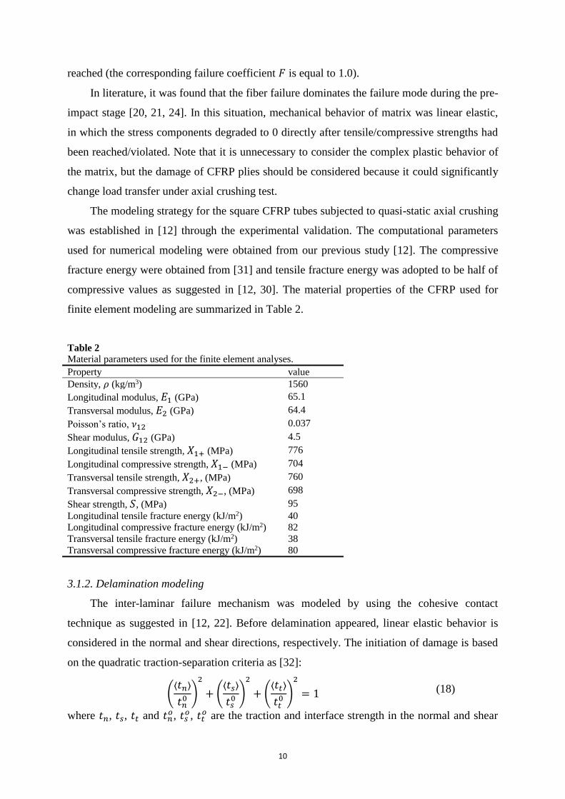
Table 2 Material parameters used for the finite element analyses.
Property value
Density, 𝜌 (kg/m3) 1560
Longitudinal modulus, 𝐸1 (GPa) 65.1
Transversal modulus, 𝐸2 (GPa) 64.4
Poisson’s ratio, 𝜈12 0.037
Shear modulus, 𝐺12 (GPa) 4.5
Longitudinal tensile strength, 𝑋1+ (MPa) 776
Longitudinal compressive strength, 𝑋1− (MPa) 704
Transversal tensile strength, 𝑋2+, (MPa) 760
Transversal compressive strength, 𝑋2−, (MPa) 698
Shear strength, 𝑆, (MPa) 95
Longitudinal tensile fracture energy (kJ/m2) 40
Longitudinal compressive fracture energy (kJ/m2) 82
Transversal tensile fracture energy (kJ/m2) 38
Transversal compressive fracture energy (kJ/m2) 80
3.1.2. Delamination modeling
The inter-laminar failure mechanism was modeled by using the cohesive contact
technique as suggested in [12, 22]. Before delamination appeared, linear elastic behavior is
considered in the normal and shear directions, respectively. The initiation of damage is based
on the quadratic traction-separation criteria as [32]:
(⟨𝑡𝑛⟩
𝑡𝑛0 )
2
+ (⟨𝑡𝑠⟩
𝑡𝑠0 )
2
+ (⟨𝑡𝑡⟩
𝑡𝑡0 )
2
= 1 (18)
where 𝑡𝑛, 𝑡𝑠, 𝑡𝑡 and 𝑡𝑛𝑜, 𝑡𝑠
𝑜, 𝑡𝑡𝑜 are the traction and interface strength in the normal and shear

11
directions, respectively.
Once the failure criteria are satisfied, the delamination between CFRP plies propagates
according to the mixed-mode damage evolution law as:
𝐺𝑛𝐶 + (𝐺𝑆
𝐶 − 𝐺𝑛𝐶) (
𝐺𝑆 + 𝐺𝑡
𝐺𝑛 + 𝐺𝑆)
𝜂
= 1 (19)
where 𝐺𝑛𝐶, 𝐺𝑆
𝐶 and 𝜂 are the critical fracture toughness parameters; 𝐺𝑛, 𝐺𝑆 and 𝐺𝑡 represent the
work done by the traction in the normal and shear directions, respectively. Table 3 lists the
inter-laminar damage parameters used in this study.
Table 3 Inter-laminar properties for CFRP tube [12].
Property value
Damage initiation 𝑡𝑛𝑜 (MPa) 54
Damage initiation 𝑡𝑠𝑜 (MPa) 70
Damage initiation 𝑡𝑛𝑜 (MPa) 70
Fracture energies 𝐺𝑛𝐶 (J/m2) 504
Fracture energies 𝐺𝑆𝐶 (J/m2) 1566
Fracture energies 𝐺𝑡𝐶 (J/m2) 1566
𝜂 2.284
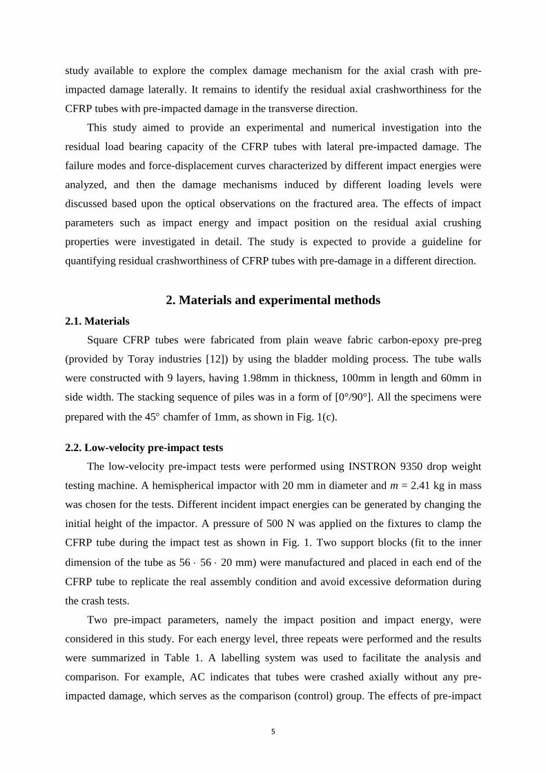
3.2. CAI model
In this study, the FE model was developed in ABAQUS 6.13/Explicit to simulate the
complex deformation and failure process during the CAI test. The schematic is shown in Fig.
3. The constitutive law for CFRP tube was coded based upon the constitutive laws as defined
in Section 3.1.1 with a VUMAT subroutine in ABAQUS.
The impactor was modeled as a rigid body with mass of 2.3 kg. The fixtures were all
modeled as rigid body. The square CFRP tube wall was meshed with 9 plies (the same
number of plain weave fabric layers adopted for the experimental specimens) using the 3D
continuum shell elements (SC8R) in ABAQUS. According to the mesh refinement study in
[21], a mesh size of 1.0 1.0 mm was adopted for the CFRP plies to predict the mechanical
responses with a proper balance of computational accuracy and efficiency. It should be noted
that to reduce the computational cost, several modeling techniques were also used here: only
one element across the thickness direction of each ply was meshed similarly to that in [23];
the inter-laminar interaction between the plies was modeled with cohesive behavior as defined
in section 3.1.2. Table 4 shows more details of the mesh definition.
The general contact algorithm was adopted here to simulate possible contact interaction
between the impactor, platens, fixtures and the CFRP tube walls in the FE simulation. A

12
tangential friction coefficient was set to be 0.15 since changing friction coefficient had rather
limited effect on the main collapse modes and crushing characteristics [12].
The FE analysis was conducted in four steps to simulate the real experimental conditions
(Fig. 3): (1) The pre-impact loading was applied by the impactor with specified energy level
while the other parts remained unchanged; (2) The impactor, top/bottom fixtures and two
blocks were removed while both the platens (front and back platen) moved away from their
initial positions toward the tube quickly with a little clearance; (3) Both the platen moved
slowly toward the pre-impacted tube to minimize the effect on equilibrium state of the CFRP
tube; (4) The front platen moved longitudinally to simulate the axial crushing process after
steps (2) and (3). Although the experimental crushing tests were carried out quasi-statically (4
mm/min), an average loading rate of 1 m/s was applied numerically and mass scaling
technique for composite tube was adopted in the crushing process in ABAQUS/Explicit
solver to reduce the computational cost while maintain the numerical accuracy as suggested in
[30].
Fig. 3. CAI set-up model.
Table 4
Mesh details in the finite element models.
Model Element type Element number
Impactor C3D8R 4,440
Fixtures R3D4 576
Platens R3D4 98
Blocks C3D8R 666
CFRP tube SC8R 196,080
Total - 201,860

13
4. Results and Discussion
4.1. Pre-impact tests
Three pre-impact energies were adopted to investigate the effect of impact energy on the
CFRP tubes in this study. Typical force-displacement curves were used to evaluate the pre-
impact characteristics. Deformation patterns around the pre-impact position were used to
identify the failure mechanism. Finally, the effects of impact energy on transverse pre-impact
mechanical characteristics were quantified.
4.1.1. Pre-impact force-displacement relationship
The dynamic contact force-displacement curves during the pre-impact process were
plotted in Fig. 4, in which the test results listed here all had the same impact number of one
and impact position. A hill-like shape with an ascending and descending range for loading
variation appeared for all the curves during the pre-impact process. Two typical patterns were
observed due to the difference in the descending stage, namely partial unloading and fully
perforating similarly to [33]. Some common features could be observed that the contact force
between the impactor and specimen increased with the impactor movement prior to the peak
force.
Correspondingly, several failure modes were unveiled in the impact/penetration area
during the pre-impact process as: matrix crack, fiber breakage and delamination between
adjacent plies [33]. In the case of pre-impact with 10 J energy (E1-P1), the deflection
decreased after the peak point but did not return to the origin point as the load decreased to
zero. This is classified as a partial rebounding process, which means that a permanent
indentation had been caused, generating a local damage and reducing the structural
stiffness/strength.
For the impact energy of 20 J and 30 J with the same impact number and position (E2-P1
and E3-P1), a plateau can be seen on the top zone of the curves, which indicates that the peak
force did not drop immediately, instead maintained at a higher level for a while prior to
perforation. Finally, the contact force decreased to zero with the increase of impactor
displacement, indicating a complete perforation of the pre-impacted side surface on the CFRP
tube. Note that no rebound was observed for these two impact energies.
14
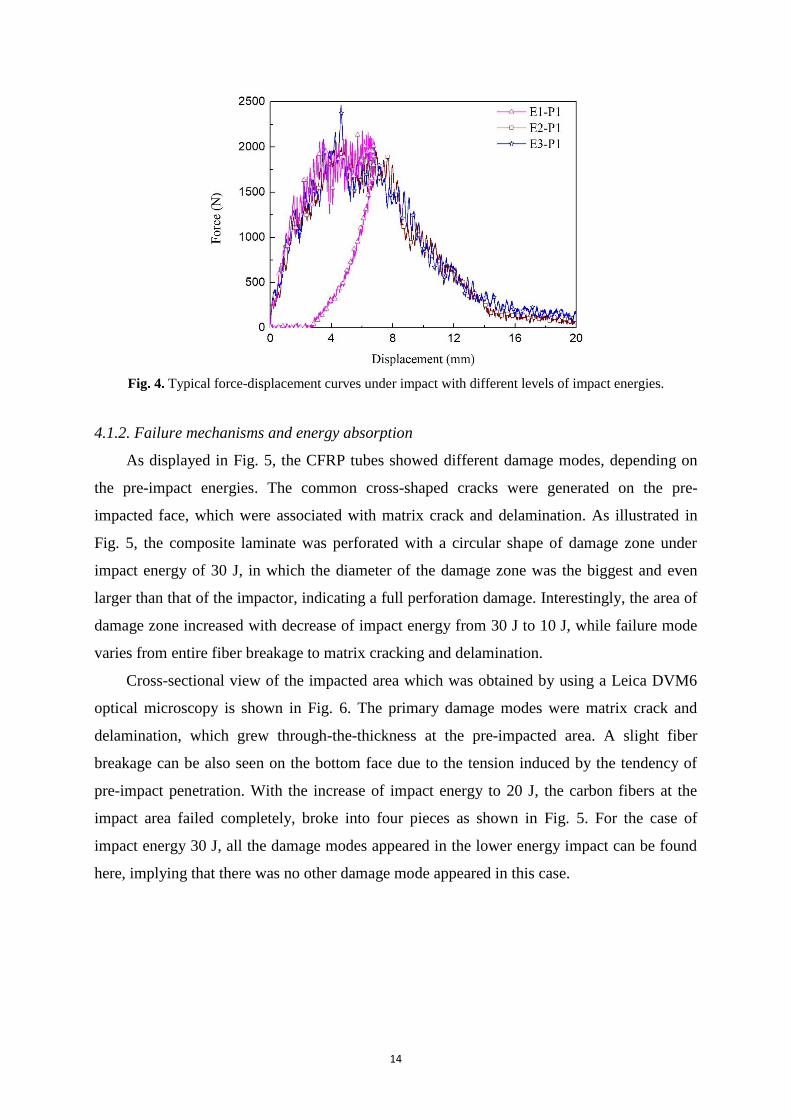
Fig. 4. Typical force-displacement curves under impact with different levels of impact energies.
4.1.2. Failure mechanisms and energy absorption
As displayed in Fig. 5, the CFRP tubes showed different damage modes, depending on
the pre-impact energies. The common cross-shaped cracks were generated on the pre-
impacted face, which were associated with matrix crack and delamination. As illustrated in
Fig. 5, the composite laminate was perforated with a circular shape of damage zone under
impact energy of 30 J, in which the diameter of the damage zone was the biggest and even
larger than that of the impactor, indicating a full perforation damage. Interestingly, the area of
damage zone increased with decrease of impact energy from 30 J to 10 J, while failure mode
varies from entire fiber breakage to matrix cracking and delamination.
Cross-sectional view of the impacted area which was obtained by using a Leica DVM6
optical microscopy is shown in Fig. 6. The primary damage modes were matrix crack and
delamination, which grew through-the-thickness at the pre-impacted area. A slight fiber
breakage can be also seen on the bottom face due to the tension induced by the tendency of
pre-impact penetration. With the increase of impact energy to 20 J, the carbon fibers at the
impact area failed completely, broke into four pieces as shown in Fig. 5. For the case of
impact energy 30 J, all the damage modes appeared in the lower energy impact can be found
here, implying that there was no other damage mode appeared in this case.

15
Fig. 5. Damage modes of composite tubes after impact with various energies.
Fig. 6. Cross-sectional views of the impacted area.
4.1.3. Effects of impact energy on pre-impact behavior
Energy absorption is the energy absorbed by the specimens during loading process which
could be calculated from the area of load-displacement curve. Table 1 summarized the results
obtained from the force-displacement curves. In this case, the crashworthiness criteria Ea
(energy absorption) and Pmax (maximum crushing force) were used to evaluate the residual
performance of the specimen under pre-impact loading.
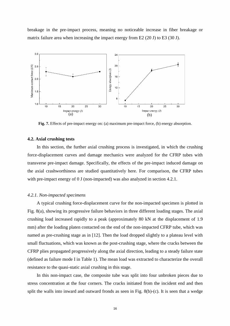
From Fig. 7(a), it is interesting to note that the maximum impact forces kept almost as a
constant with increase of the impact energy. This phenomenon agrees well with that of CFRP
laminates impacted with different levels of energies as reported in [16], where a relatively
small fluctuation of maximum force could be found around the penetration energy. On the
other hand, Fig. 7(b) shows that the average residual energy absorption of the CFRP
specimens increased dramatically from 7.4 J to 18.3 J with the increase of the pre-impact
energy from 10 J to 20 J; but a lower increase value of 2.2 J appears when the pre-impact
energy increased from 20 J to 30 J. This can be explained according to the damage modes as
shown in Fig. 6. Impact energy is mostly absorbed as matrix cracking, delamination and fiber
16
breakage in the pre-impact process, meaning no noticeable increase in fiber breakage or
matrix failure area when increasing the impact energy from E2 (20 J) to E3 (30 J).
Fig. 7. Effects of pre-impact energy on: (a) maximum pre-impact force, (b) energy absorption.
4.2. Axial crushing tests
In this section, the further axial crushing process is investigated, in which the crushing
force-displacement curves and damage mechanics were analyzed for the CFRP tubes with
transverse pre-impact damage. Specifically, the effects of the pre-impact induced damage on
the axial crashworthiness are studied quantitatively here. For comparison, the CFRP tubes
with pre-impact energy of 0 J (non-impacted) was also analyzed in section 4.2.1.
4.2.1. Non-impacted specimens
A typical crushing force-displacement curve for the non-impacted specimen is plotted in
Fig. 8(a), showing its progressive failure behaviors in three different loading stages. The axial
crushing load increased rapidly to a peak (approximately 80 kN at the displacement of 1.9
mm) after the loading platen contacted on the end of the non-impacted CFRP tube, which was
named as pre-crushing stage as in [12]. Then the load dropped slightly to a plateau level with
small fluctuations, which was known as the post-crushing stage, where the cracks between the
CFRP plies propagated progressively along the axial direction, leading to a steady failure state
(defined as failure mode I in Table 1). The mean load was extracted to characterize the overall
resistance to the quasi-static axial crushing in this stage.
In this non-impact case, the composite tube was split into four unbroken pieces due to
stress concentration at the four corners. The cracks initiated from the incident end and then
split the walls into inward and outward fronds as seen in Fig. 8(b)-(c). It is seen that a wedge
(a) (b)

17
was formed at the interface of the inward and outward fronds, which separated the wall into
two halves continuously during the loading process. For the outward fronds, large amounts of
small fragments could be found due to excessive bent and curled downwards, together with
matrix cracks and delamination. The length of fragments varied with the distance from the
center line of tubal wall (position of the middle wall wedge as shown in Fig. 8(c)). Shear
failure could also be observed in the inward folding. The indicators of crashworthiness, e.g.
the mean load and energy absorption, were calculated as summarized in Table 1.
Fig. 8. Experimental results of AC: (a) force-displacement curve and damage propagation behavior; (b) and
(c) microscopic image after axial crashing.
4.2.2. Specimens with single pre-impact
The axial crushing tests of the singly pre-impacted tube with different energy levels is
studied here. Fig. 9 shows the axial force-displacement curves of the CFRP tubes with three
pre-impact energies impacted at the same position of P1. There is relatively large difference in
comparison with that of non-impacted case (Fig. 8(a)). From Fig. 9, three distinct stages could
be identified, namely pre-crushing (stage I), partial loading with local excessive deformation
(stage II) and secondary load-bearing (stage III). The corresponding photographs at the four

18
different crushing stages, specifically U = 2 mm, U = 10 mm, U = 20 mm and U = 48 mm
(near the pre-impacted penetration area) are shown in Fig. 10 for better understanding of the
progressive crushing process in the following analysis.
Fig. 9. Force-displacement curves after being impacted with different energies.

19
Fig. 10. Crushing process of the specimens after being impacted with different energies.
For the singly pre-impacted tube with impact energy of 10 J, the average axial peak
crushing force was only 67.8 kN, which is considerably lower than that of the non-impacted
specimens (shown in Fig. 8(a)). Different from the failure mode I (as shown in Fig. 8(c)), the
loading capacity of CFRP structure appeared partial reduction with progressive failure until
the catastrophic drop caused by the transverse pre-impact damage (defined as failure mode
II). With increase in the axial crushing displacement up to U = 20 mm, the failure mechanism
was mainly from two aspects: a) the accumulation of internal damages near the pre-impact
area; and b) cracks propagation in the axial direction (outward fronds as seen in Fig. 10).
Several inward bulges on the tubal wall near the pre-impacted damage area were found due to
the local stress concentration induced by the pre-impacted damage (Fig. 10). Then the
crushing force dropped dramatically to about 10 kN and lasted until the secondary load
climbing from the displacement around U = 40 mm. It can be seen from Fig. 10 that cracks
appeared around the edges of the pre-impact position and grew circumferentially along the

20
perimeter of the tubal walls, which led to catastrophic fracture of the upper half tube into
several pieces and then slipped toward inside or outside the lower half of the tube. This can be
further seen from an isometric view as shown in Fig. 11 (U = 48 mm). In the third stage, the
resistant load increased dramatically to 50 kN, which was approximately equal to that prior to
U = 10 mm with the progressive folding and delamination of the lower half of the tubal walls.
Further validations can be conducted with partial crack fronds, inward and outward fronds as
shown in Fig. 12.
The axial force-displacement curves for 20 J and 30 J shared many common features and
exhibited a rather different mode with E1-P1 (10 J) which was classified to be failure mode
III as summarized in Table 1. The contact force increased rapidly to a peak (at about U = 2
mm) after the loading platen contacted with the incident end of tube (stage I: pre-crushing).
Then the load decreased drastically to a relatively stable level around 9 kN (approximately
15% of the peak force). The significant drop of reaction force was due to the cracks initiated
near the pre-impacted damage zone and propagated along the circumference of tubal walls as
seen from Fig. 10 and Fig. 11. Subsequently, the upper half of the tube split into several
pieces until the crushing load climbed again at about U = 40 mm. In this stage, it can be found
that little difference between the force-displacement curves existed regardless of the different
failure modes and damage evolution processes of the upper half tube (namely, the residual
pieces split in the axial direction, sliding inside or outside the lower half of the tube). Finally,
the load increased to a new peak as seen in Fig. 9 and then decreased gradually due to the
complex fracture mechanism as seen in Fig. 10. Also, a relatively less extent of progressive
folding in the upper and lower halves of E2-P1/E3-P1 could be found compared with that of
the E1-P1 case.
21
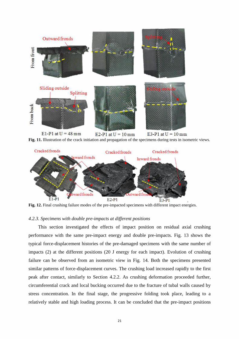
Fig. 11. Illustration of the crack initiation and propagation of the specimens during tests in isometric views.
Fig. 12. Final crushing failure modes of the pre-impacted specimens with different impact energies.
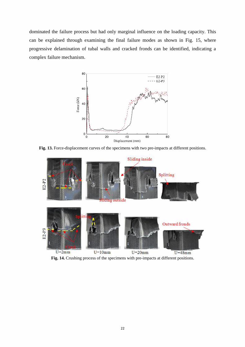
4.2.3. Specimens with double pre-impacts at different positions
This section investigated the effects of impact position on residual axial crushing
performance with the same pre-impact energy and double pre-impacts. Fig. 13 shows the
typical force-displacement histories of the pre-damaged specimens with the same number of
impacts (2) at the different positions (20 J energy for each impact). Evolution of crushing
failure can be observed from an isometric view in Fig. 14. Both the specimens presented
similar patterns of force-displacement curves. The crushing load increased rapidly to the first
peak after contact, similarly to Section 4.2.2. As crushing deformation proceeded further,
circumferential crack and local bucking occurred due to the fracture of tubal walls caused by
stress concentration. In the final stage, the progressive folding took place, leading to a
relatively stable and high loading process. It can be concluded that the pre-impact positions
22
dominated the failure process but had only marginal influence on the loading capacity. This
can be explained through examining the final failure modes as shown in Fig. 15, where
progressive delamination of tubal walls and cracked fronds can be identified, indicating a
complex failure mechanism.
Fig. 13. Force-displacement curves of the specimens with two pre-impacts at different positions.
Fig. 14. Crushing process of the specimens with pre-impacts at different positions.

23
Fig. 15. Final crushing failure modes of the specimens with pre-impacts at different positions.
4.2.4. Effects of transverse pre-impacts on axial crushing characteristics
The aforementioned results demonstrated the effects of pre-impact energy/position on
residual axial crushing performance. Detailed results, such as peak force, mean load, crush
force efficiency and energy absorption, are compared in Table 1. Further assessment is
conducted based on the mean values and error bars of all the specimens as shown in Fig. 16.
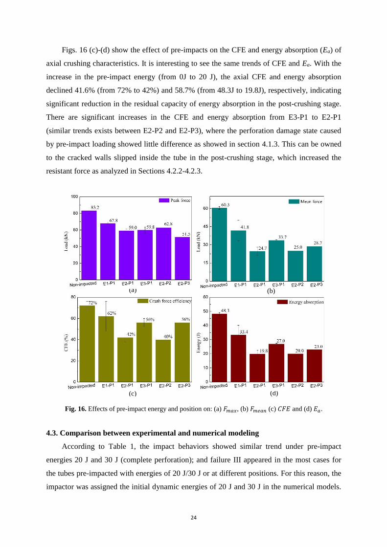
Reduction about 28% in the peak force (from 83.2 kN to 59 kN) can be observed with
the increase of the pre-impact energy from 0 J (non-impact) to 20 J (single pre-impact) in Fig.
16 (a). Nevertheless, when the impact energy increased to 30 J, the peak force remained
almost unchanged due to the similar failure mode as depicted in Section 4.1.2. The reason was
due to the fact that the failure area of fiber and matrix damage caused by the pre-impact
increased from the local indentation damage to complete perforation of the wall; thus, the
load bearing capacity reduced mostly. After complete perforation, there was no room for
further increase in damage and failure area as shown in Fig. 5, indicating no increase in
residual capacity of crushing resistance. This result is also similar to that from the study on
the load bearing capacity of perforated square tubes [17], where the holes with different
diameters, rather than pre-impacted damage or perforation, were prepared for crushing
analysis, leading to a 3-22% reduction in the residual strength.
For the double pre-impacts with E2 (20 J) at different positions on either the adjacent
walls (P2) or opposite walls (P3) (refer to Fig. 2), it can be observed from Fig. 16 (a) that the
peak impact force at the P3 position (51.5 kN) was about 18% lower than that on P2 position
(62.8 kN). On contrary, a relatively small variation in the peak force can be found between the
double pre-impacts at the adjacent P2 position and the single pre-impact. This result differs
with that from [17], where peak force remained almost unchanged regardless of distribution
of the two holes on the adjacent or on the opposite walls. The mean crushing forces of E2-P2
(25 kN) was similar to E2-P1 (24.7 kN) but an approximately 12.9% reduction in comparison
with E2-P3 (28.7 kN).
24
Figs. 16 (c)-(d) show the effect of pre-impacts on the CFE and energy absorption (Ea) of
axial crushing characteristics. It is interesting to see the same trends of CFE and Ea. With the
increase in the pre-impact energy (from 0J to 20 J), the axial CFE and energy absorption
declined 41.6% (from 72% to 42%) and 58.7% (from 48.3J to 19.8J), respectively, indicating
significant reduction in the residual capacity of energy absorption in the post-crushing stage.
There are significant increases in the CFE and energy absorption from E3-P1 to E2-P1
(similar trends exists between E2-P2 and E2-P3), where the perforation damage state caused
by pre-impact loading showed little difference as showed in section 4.1.3. This can be owned
to the cracked walls slipped inside the tube in the post-crushing stage, which increased the
resistant force as analyzed in Sections 4.2.2-4.2.3.
Fig. 16. Effects of pre-impact energy and position on: (a) 𝐹𝑚𝑎𝑥, (b) 𝐹𝑚𝑒𝑎𝑛 (c) 𝐶𝐹𝐸 and (d) 𝐸𝑎.
4.3. Comparison between experimental and numerical modeling
According to Table 1, the impact behaviors showed similar trend under pre-impact
energies 20 J and 30 J (complete perforation); and failure III appeared in the most cases for
the tubes pre-impacted with energies of 20 J/30 J or at different positions. For this reason, the
impactor was assigned the initial dynamic energies of 20 J and 30 J in the numerical models.
(c)
(a)
(d)
(b)
25
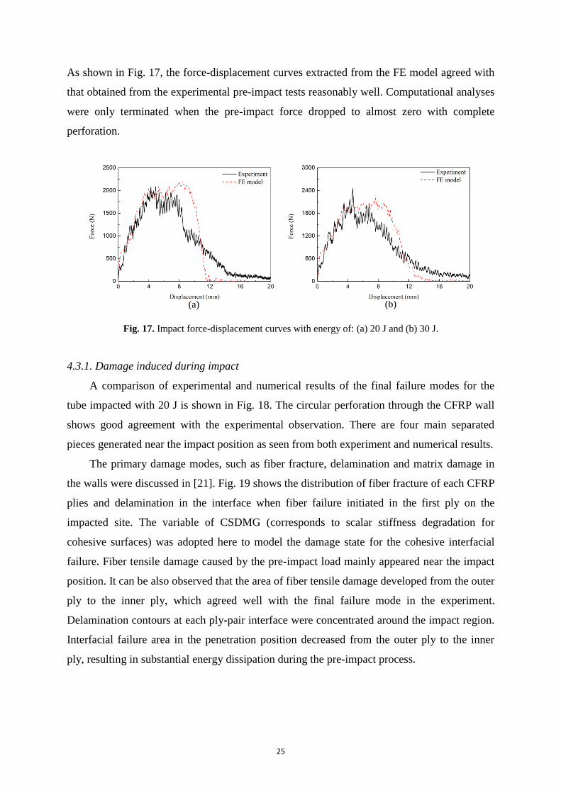
As shown in Fig. 17, the force-displacement curves extracted from the FE model agreed with
that obtained from the experimental pre-impact tests reasonably well. Computational analyses
were only terminated when the pre-impact force dropped to almost zero with complete
perforation.
Fig. 17. Impact force-displacement curves with energy of: (a) 20 J and (b) 30 J.
4.3.1. Damage induced during impact
A comparison of experimental and numerical results of the final failure modes for the
tube impacted with 20 J is shown in Fig. 18. The circular perforation through the CFRP wall
shows good agreement with the experimental observation. There are four main separated
pieces generated near the impact position as seen from both experiment and numerical results.
The primary damage modes, such as fiber fracture, delamination and matrix damage in
the walls were discussed in [21]. Fig. 19 shows the distribution of fiber fracture of each CFRP
plies and delamination in the interface when fiber failure initiated in the first ply on the
impacted site. The variable of CSDMG (corresponds to scalar stiffness degradation for
cohesive surfaces) was adopted here to model the damage state for the cohesive interfacial
failure. Fiber tensile damage caused by the pre-impact load mainly appeared near the impact
position. It can be also observed that the area of fiber tensile damage developed from the outer
ply to the inner ply, which agreed well with the final failure mode in the experiment.
Delamination contours at each ply-pair interface were concentrated around the impact region.
Interfacial failure area in the penetration position decreased from the outer ply to the inner
ply, resulting in substantial energy dissipation during the pre-impact process.
(a) (b)

26
Fig. 18. Experimental and numerical results of failure mode for the tube pre-impacted with 20 J.
Fig. 19. Damage contours on the pre-impacted surface for the tube pre-impacted with 20 J at the time of
first ply failure.
4.3.2. Failure in the axial crushing stage
Comparison of axial crushing force-displacement curves for perforated tube (E2-P1) is
shown in Fig. 20. It can be observed that, nevertheless, the FE model predicted the trends of
crushing force-displacement curves with limited accuracy. This is because the FE modeling
accuracy of pre-impacted damage could be carried forward to the subsequent axial crushing
stage. As shown in Fig. 17(a), although the FE peak pre-impact load was fairly close to the
experimental results, the FE result exhibited a longer plateau of displacement, indicating that
removal of the damaged elements was unable to replicate the experimental test accurately.
These elements would have continuously borne axial loading in the crushing stage, making
the peak load substantially higher. However, these elements were removed under the axial
crushing load rather quickly, making the displacement smaller than the experimental crushing
test.
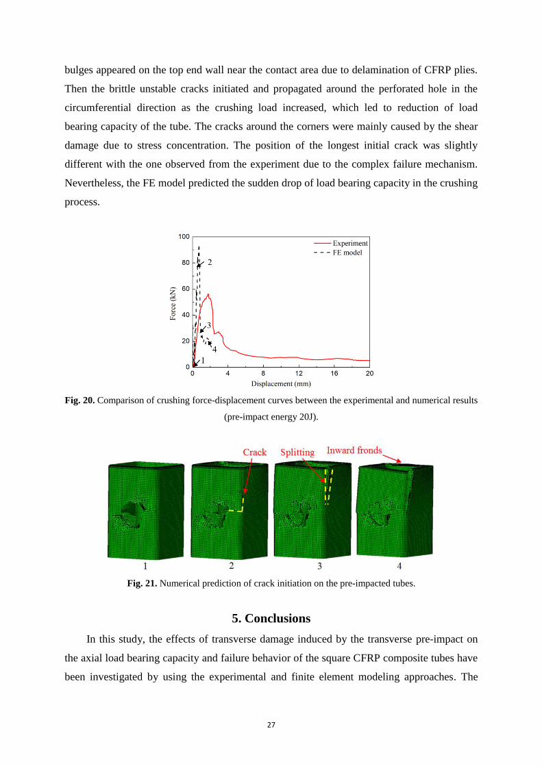
Fig. 21 shows the FE prediction of failure mode for the perforated tube with the pre-
impact energy of 20 J at different crushing stages as shown in Fig. 20. It is observed that the
crack initiated and propagated quickly, thus decreasing loading capacity. Several inwards
27
bulges appeared on the top end wall near the contact area due to delamination of CFRP plies.
Then the brittle unstable cracks initiated and propagated around the perforated hole in the
circumferential direction as the crushing load increased, which led to reduction of load
bearing capacity of the tube. The cracks around the corners were mainly caused by the shear
damage due to stress concentration. The position of the longest initial crack was slightly
different with the one observed from the experiment due to the complex failure mechanism.
Nevertheless, the FE model predicted the sudden drop of load bearing capacity in the crushing
process.
Fig. 20. Comparison of crushing force-displacement curves between the experimental and numerical results
(pre-impact energy 20J).
Fig. 21. Numerical prediction of crack initiation on the pre-impacted tubes.
5. Conclusions
In this study, the effects of transverse damage induced by the transverse pre-impact on
the axial load bearing capacity and failure behavior of the square CFRP composite tubes have
been investigated by using the experimental and finite element modeling approaches. The

28
CFRP tubes with transversely pre-impacted damage were tested through quasi-static crushing
in the axial direction. The failure mechanisms of transverse pre-impact and axial crushing was
studied in detail through finite element analysis with a user-defined material model. Within its
limitations, the following conclusions can be drawn:
(1) Two different failure modes were observed in the axial quasi-static crushing test for
the specimens with single pre-impact. With the increase in the pre-impact energy, the residual
crashworthiness performance decreased in terms of peak force, mean force, energy absorption
and crush force efficiency.
(2) The residual crushing capacity and the failure mode were more dependent on the pre-
impact energy than impact position. Compared with single pre-impact (e.g. E2-P1 with
impact energy of 20J), the specimen with adjacent double pre-impacting positions (P2)
showed slight reduction in the residual crushing energy absorption capacity while the opposite
position had a marginal increase of 16.2% (P3).
(3) FE simulation showed that the CDM (continuum damage mechanics) model was able
to properly replicate the different failure modes such as fiber failure and delamination caused
by the pre-impact damage in the first stage. In the second stage, the FE model allows to
predict the axial crushing behavior in terms of crack initiation and propagation. However,
further study is still needed to enhance the accuracy of such a two-stage crushing process.
(4) Besides the residual crashworthiness of CFRP structures with pre-impact damage
under axial crushing, the residual performance of CFRP structures with pre-impact damage
under oblique [34-37] and transverse loading [38, 39] also should be comprehensively
investigated in the future.
Acknowledgments
This work is supported by National Natural Science Foundation of China (51575172,
51475155) and the Open Fund of the State Key Laboratory for Strength and Vibration of
Mechanical Structures of Xi’an Jiaotong University (SV2017-KF-24). Dr Guangyong Sun is a
recipient of Australian Research Council (ARC) Discovery Early Career Researcher Award
(DECRA) in the University of Sydney.
References
[1] P. Feraboli, A. Masini, L. Taraborrelli, A. Pivetti, Integrated development of CFRP structures for a topless high performance vehicle, Composite Structures 78(4) (2007) 495-506.
29
[2] Q. Liu, Y. Lin, Z. Zong, G. Sun, Q. Li, Lightweight design of carbon twill weave fabric composite body structure for electric vehicle, Composite Structures 97 (2013) 231-238. [3] J. Obradovic, S. Boria, G. Belingardi, Lightweight design and crash analysis of composite frontal impact energy absorbing structures, Composite Structures 94(2) (2012) 423-430. [4] G. Sun, H. Zhang, J. Fang, G. Li, Q. Li, Multi-objective andd multi-case reliability-based design optimization for tailor rolled blank (TRB) structures , Structural and Multidisciplinary Optimization 55(5) (2017) 1899-1916. [5] Q. Liu, Z. Ou, Z. Mo, Q. Li, D. Qu, Experimental investigation into dynamic axial impact responses of double hat shaped CFRP tubes, Composites Part B: Engineering 79 (2015) 494-504. [6] A.G. Mamalis, D.E. Manolakos, M.B. Ioannidis, D.P. Papapostolou, On the response of thin-walled CFRP composite tubular components subjected to static and dynamic axial compressive loading: experimental, Composite Structures 69(4) (2005) 407-420. [7] A.G. Mamalis, D.E. Manolakos, M.B. Ioannidis, D.P. Papapostolou, Crashworthy characteristics of axially statically compressed thin-walled square CFRP composite tubes: experimental, Composite Structures 63(3-4) (2004) 347-360. [8] X. Jia, G. Chen, Y. Yu, G. Li, J. Zhu, X. Luo, C. Duan, X. Yang, D. Hui, Effect of geometric factor, winding angle and pre-crack angle on quasi-static crushing behavior of filament wound CFRP cylinder, Composites Part B: Engineering 45(1) (2013) 1336-1343. [9] D. Siromani, G. Henderson, D. Mikita, K. Mirarchi, R. Park, J. Smolko, J. Awerbuch, T.-M. Tan, An experimental study on the effect of failure trigger mechanisms on the energy absorption capability of CFRP tubes under axial compression, Composites Part A: Applied Science and Manufacturing 64 (2014) 25-35. [10] J. Meredith, E. Bilson, R. Powe, E. Collings, K. Kirwan, A performance versus cost analysis of prepreg carbon fibre epoxy energy absorption structures, Composite Structures 124 (2015) 206-213. [11] C. McGregor, R. Vaziri, X. Xiao, Finite element modelling of the progressive crushing of braided composite tubes under axial impact, International Journal of Impact Engineering 37(6) (2010) 662-672. [12] G. Zhu, G. Sun, G. Li, A. Cheng, Q. Li, Modeling for CFRP structures subjected to quasi-static crushing, Composite Structures 184 (2018) 41-55. [13] X. Xiao, M.E. Botkin, N.L. Johnson, Axial crush simulation of braided carbon tubes using MAT58 in LS-DYNA, Thin-Walled Structures 47(6-7) (2009) 740-749. [14] D. Siromani, J. Awerbuch, T.-M. Tan, Finite element modeling of the crushing behavior of thin-walled CFRP tubes under axial compression, Composites Part B: Engineering 64 (2014) 50-58. [15] B.P. Bussadori, K. Schuffenhauer, A. Scattina, Modelling of CFRP crushing structures in explicit crash analysis, Composites Part B: Engineering 60 (2014) 725-735. [16] Q. Liu, O. Guo, Y. Ju, Y. Lin, Q. Li, Impact responses and residual flexural properties of narrow CFRP laminates, Composite Structures 111 (2014) 332-339. [17] Q. Liu, J. Ma, X. Xu, Y. Wu, Q. Li, Load bearing and failure characteristics of perforated square CFRP tubes under axial crushing, Composite Structures 160 (2017) 23-35. [18] E. Guades, T. Aravinthan, Residual properties of square FRP composite tubes subjected to repeated axial impact, Composite Structures 95 (2013) 354-365. [19] T.A. Sebaey, E. Mahdi, Crashworthiness of pre-impacted glass/epoxy composite tubes, International Journal of Impact Engineering 92 (2016) 18-25. [20] S.X. Wang, L.Z. Wu, L. Ma, Low-velocity impact and residual tensile strength analysis to carbon fiber composite laminates, Materials & Design 31(1) (2010) 118-125. [21] M.R. Abir, T.E. Tay, M. Ridha, H.P. Lee, Modelling damage growth in composites subjected to impact and compression after impact, Composite Structures 168 (2017) 13-25. [22] W. Tan, B.G. Falzon, L.N.S. Chiu, M. Price, Predicting low velocity impact damage and Compression-After-Impact (CAI) behaviour of composite laminates, Composites Part A: Applied Science and Manufacturing 71 (2015) 212-226. [23] E.V. González, P. Maimí, P.P. Camanho, A. Turon, J.A. Mayugo, Simulation of drop-weight impact and compression after impact tests on composite laminates, Composite Structures 94(11) (2012) 3364-3378. [24] S. Rivallant, C. Bouvet, N. Hongkarnjanakul, Failure analysis of CFRP laminates subjected to compression after impact: FE simulation using discrete interface elements, Composites Part A: Applied Science and Manufacturing 55 (2013) 83-93. [25] P.A.A.E. Mendes, M.V. Donadon, Numerical prediction of compression after impact behavior of woven composite laminates, Composite Structures 113 (2014) 476-491. [26] G. Zhu, G. Sun, Q. Liu, G. Li, Q. Li, On crushing characteristics of different configurations of metal-composites hybrid tubes, Composite Structures 175 (2017) 58-69. [27] M.E. Deniz, R. Karakuzu, M. Sari, B.M. Icten, On the residual compressive strength of the glass–epoxy tubes
30
subjected to transverse impact loading, Journal of Composite Materials 46(6) (2011) 737-745. [28] G. Sun, S. Li, Q. Liu, G. Li, Q. Li, Experimental study on crashworthiness of empty/aluminum foam/honeycomb-filled CFRP tubes, Composite Structures 152 (2016) 969-993. [29] M.V. Donadon, L. Iannucci, B.G. Falzon, J.M. Hodgkinson, S.F.M. de Almeida, A progressive failure model for composite laminates subjected to low velocity impact damage, Computers & Structures 86(11-12) (2008) 1232-1252. [30] V.S. Sokolinsky, K.C. Indermuehle, J.A. Hurtado, Numerical simulation of the crushing process of a corrugated composite plate, Composites Part A: Applied Science and Manufacturing 42(9) (2011) 1119-1126. [31] Y. Shi, T. Swait, C. Soutis, Modelling damage evolution in composite laminates subjected to low velocity impact, Composite Structures 94(9) (2012) 2902-2913. [32] Hibbitt, Karlsson, Sorensen, ABAQUS/standard User's Manual, Hibbitt, Karlsson & Sorensen2001. [33] D. Liu, Characterization of Impact Properties and Damage Process of Glass/Epoxy Composite Laminates, Journal of Composite Materials 38(16) (2004) 1425-1442. [34] G. Sun, T. Liu, J. Fang, G.P. Steven, Q. Li, Configuration optimization of multi-cell topologies for multiple oblique loads, Structural and Multidisciplinary Optimization 57(2) (2018) 469-488. [35] G. Zhu, G. Sun, H. Yu, S. Li, Q. Li, Energy absorption of metal. composite and metal/composite hybrid structures under oblique crushing loading, International Journal of Mechanical Sciences 135 (2018) 458-483. [36] G. Sun, S. Li, G. Li, Q. Li, On crashing behaviors of aluminium/CFRP tubes subjected to axial and oblique loading: An experimental study, Composites Part B: Engineering 145 (2018) 47-56. [37] G. Li, F. Xu, G. Sun, Q. Li, A comparative study on thin-walled structures with functionally graded thickness (FGT) and tapered tube withstanding oblique impact loading, International Journal of Impact Engineering 77 (2015) 68-83. [38] H. Zhang, G. Sun, Z. Xiao, G. Li, Q. Li, Bending characteristics of top-hat structures through tailor rolled blank (TRB) process, Thin-Walled Structures 123 (2018) 420-440. [39] G. Sun, T. Pang, G. Zheng, J. Song, Q. Li, On energy absorption of functionary graded tubes under transverser loading, International Journal of Mechanical Sciences 115 (2016) 465-480.