Embed Size (px)
Citation preview
March 2014
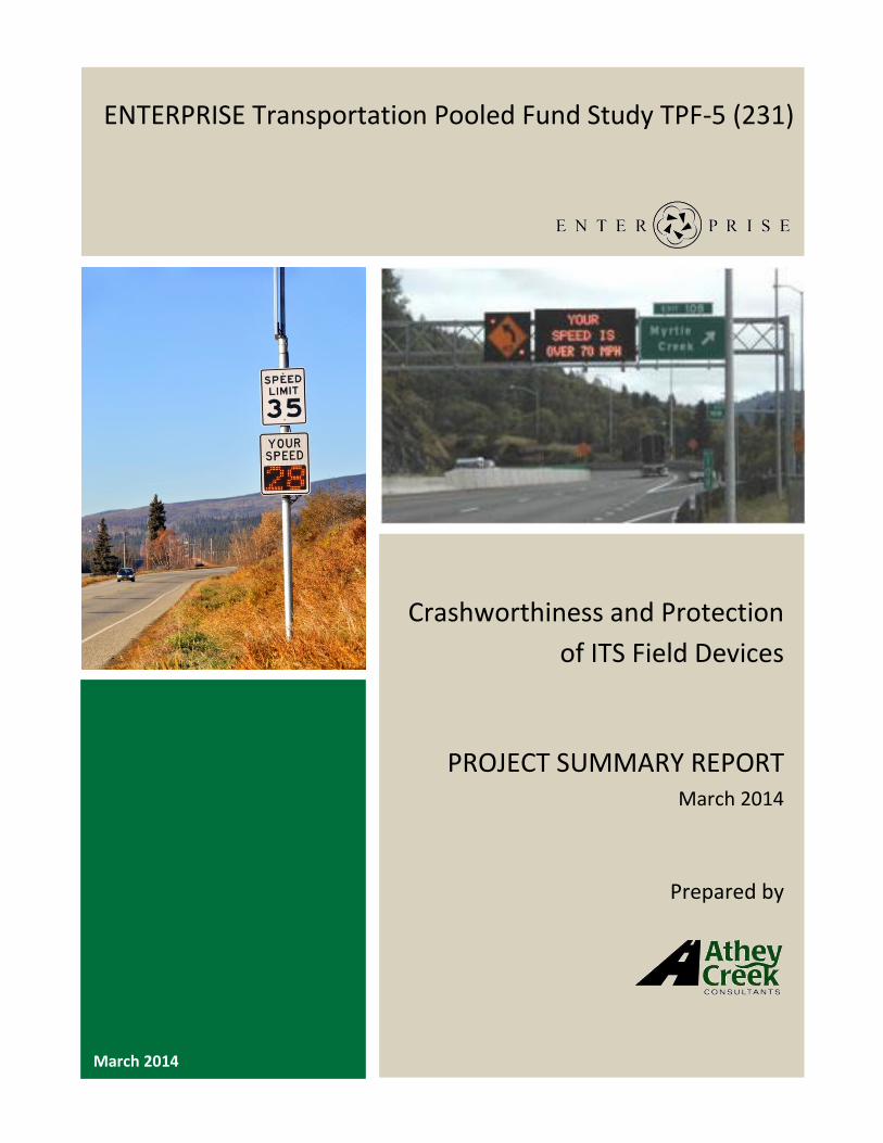
ENTERPRISE Transportation Pooled Fund Study TPF-5 (231)
Crashworthiness and Protection
of ITS Field Devices
PROJECT SUMMARY REPORT March 2014
Prepared by
ENTERPRISE Crashworthiness and Protection of ITS Field Devices – March 2014 i
Acknowledgements
This document was prepared for the ENTERPRISE Transportation Pooled Fund TPF-5(231) program. With
agencies from North America and Europe, the main purpose of ENTERPRISE is to use the pooled
resources of its members, private sector partners and the United States federal government to develop,
evaluate and deploy Intelligent Transportation Systems (ITS).
Project Champion
Bill Legg, Washington State Department of Transportation and Jon Jackels, Minnesota Department of
Transportation, were the ENTERPRISE Project Champions for this effort.
Members of ENTERPRISE Pooled Fund
Arizona Department of Transportation
Federal Highway Administration
Georgia Department of Transportation
Idaho Transportation Department
Illinois Department of Transportation
Iowa Department of Transportation
Kansas Department of Transportation
Maricopa County, Arizona
Michigan Department of Transportation
Minnesota Department of Transportation
Mississippi Department of Transportation
Oklahoma Department of Transportation
Ministry of Transportation Ontario
Pennsylvania Department of Transportation
Dutch Ministry of Transport (Rijkswaterstaat)
Texas Department of Transportation
Transport Canada
Virginia Department of Transportation
Washington State Department of Transportation
ENTERPRISE Crashworthiness and Protection of ITS Field Devices – March 2014 ii
Table of Contents
Executive Summary ............................................................................................................................1
1.0 Background and Introduction ..................................................................................................2
2.0 Summary of Research .............................................................................................................3
2.1 Summary of Step One – Preliminary Research ............................................................................. 3
2.2 Summary of Step Two – Interim Update & Selection of Project Focus ........................................ 4
2.3 Summary of Step Three – ITS Devices with Breakaway Supports ................................................ 4
2.4 Summary of Step Four – Research Additional Tools and Resources ............................................ 5
2.5 Summary of Step Five – Preparation of Project Summary Report ............................................... 7
3.0 Project Findings ......................................................................................................................8
3.1 Summary of Findings - Available Resources for Crashworthiness ................................................ 8
3.2 Resources Related to Shielding Devices within the Clear Zone .................................................. 10
3.3 Resources Related to Installing Breakaway Supports in the Clear Zone .................................... 10
3.4 Overview of Guidance and Support Resources .......................................................................... 16
4.0 Conclusions .......................................................................................................................... 17
Appendix A: Example Design Drawings for ITS Devices with Breakaway Supports ............................. 18
ENTERPRISE Crashworthiness and Protection of ITS Field Devices – March 2014 1
Executive Summary
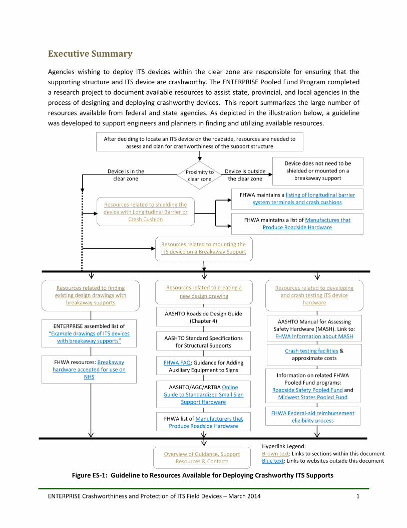
Agencies wishing to deploy ITS devices within the clear zone are responsible for ensuring that the
supporting structure and ITS device are crashworthy. The ENTERPRISE Pooled Fund Program completed
a research project to document available resources to assist state, provincial, and local agencies in the
process of designing and deploying crashworthy devices. This report summarizes the large number of
resources available from federal and state agencies. As depicted in the illustration below, a guideline
was developed to support engineers and planners in finding and utilizing available resources.
Figure ES-1: Guideline to Resources Available for Deploying Crashworthy ITS Supports
After deciding to locate an ITS device on the roadside, resources are needed to assess and plan for crashworthiness of the support structure
FHWA maintains a listing of longitudinal barrier system terminals and crash cushions
FHWA maintains a list of Manufactures that
Produce Roadside Hardware
Device does not need to be shielded or mounted on a
breakaway support
Device is outside the clear zone
Resources related to mounting the ITS device on a Breakaway Support
Resources related to shielding the device with Longitudinal Barrier or
Crash Cushion
Device is in the clear zone
Proximity to clear zone
Resources related to creating a
new design drawing
Resources related to developing and crash testing ITS device
hardware
AASHTO Roadside Design Guide (Chapter 4)
AASHTO Standard Specifications for Structural Supports
FHWA FAQ: Guidance for Adding
Auxiliary Equipment to Signs
AASHTO/AGC/ARTBA Online
Guide to Standardized Small Sign Support Hardware
FHWA list of Manufacturers that
Produce Roadside Hardware
Overview of Guidance, Support Resources & Contacts
Resources related to finding existing design drawings with
breakaway supports
ENTERPRISE assembled list of “Example drawings of ITS devices
with breakaway supports”
FHWA resources: Breakaway hardware accepted for use on
NHS
AASHTO Manual for Assessing Safety Hardware (MASH). Link to: FHWA Information about MASH
Crash testing facilities & approximate costs
Information on related FHWA
Pooled Fund programs: Roadside Safety Pooled Fund and
Midwest States Pooled Fund
FHWA Federal-aid reimbursement eligibility process
Hyperlink Legend: Brown text: Links to sections within this document Blue text: Links to websites outside this document
ENTERPRISE Crashworthiness and Protection of ITS Field Devices – March 2014 2
1.0 Background and Introduction
State and local transportation agencies often deploy technology solutions that are commonly referred to
as Intelligent Transportation Systems (ITS). Examples of ITS deployments range from traffic management
centers to on-line traveler information websites to “smart” traffic control devices to in-vehicle
deployments of driver assist systems. Many ITS deployments include the deployment of a roadside
device that is intended to be viewed by drivers on the road network (e.g. dynamic signs, static signs with
flashing beacons, ramp meter lights). Other ITS deployments are intended to gather information from
the roadside (e.g. cameras or road weather monitoring systems). With systems such as these examples,
there is often the need to locate ITS devices close to the road, and therefore within the clear zone. The
AASHTO Roadside Design Guide defines a clear zone as the total roadside border area, starting at the
edge of the traveled way, available for safe use by errant vehicles. For devices located within the clear
zone, the Manual on Uniform Traffic Control Devices (MUTCD)1 requires these devices to be breakaway
or shielded by a barrier.
For agencies wishing to deploy ITS devices within the clear zone, the engineers responsible for designing
the structure to hold the ITS device(s) must ensure the supporting structure is breakaway, if the devices
is not shielded by a barrier. Unlike static signs that are often the same dimensions and weights as other
similar signs, the placement of ITS devices on the roadside is not always a reproducible activity. For
example, one dynamic message sign might be connected to a 2’x2’ solar panel while another dynamic
message sign might be connected to power cables and not rely on solar. For these reasons, there are
multiple parameters to consider when designing the crashworthiness of the ITS device and supporting
structure.
The objective of this project was to research available documentation to help ENTERPRISE member
states understand if there are existing appropriate crashworthy supports for ITS Field Devices (signs,
detectors, solar panels, control cabinets, etc.), that meet federal MUTCD and American Association of
State Highway Transportation Officials (AASHTO) standards and guidelines for crashworthy roadside
appurtenances. This includes roadside appurtenances that have been successfully crash tested in
accordance with a national standard such as the National Cooperative Highway Research Program
Report 350, “Recommended Procedures for the Safety Performance Evaluation of Highway Features" or
the Manual for Assisting Safety Hardware (MASH).
A secondary objective of the research was to determine if additional crashworthy supports are required
to meet the needs of ITS deployments. During the course of the project, a third objective emerged. This
objective was to create a summary of resources to support decision-making when designing and
deploying ITS devices in the clear zone.
1 Weblink: http://mutcd.fhwa.dot.gov/
ENTERPRISE Crashworthiness and Protection of ITS Field Devices – March 2014 3
2.0 Summary of Research
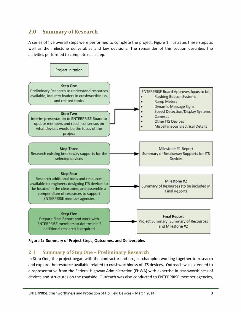
A series of five overall steps were performed to complete the project. Figure 1 illustrates these steps as
well as the milestone deliverables and key decisions. The remainder of this section describes the
activities performed to complete each step.
Figure 1: Summary of Project Steps, Outcomes, and Deliverables
2.1 Summary of Step One – Preliminary Research In Step One, the project began with the contractor and project champion working together to research
and explore the resource available related to crashworthiness of ITS devices. Outreach was extended to
a representative from the Federal Highway Administration (FHWA) with expertise in crashworthiness of
devices and structures on the roadside. Outreach was also conducted to ENTERPRISE member agencies,
ENTERPRISE Crashworthiness and Protection of ITS Field Devices – March 2014 4
who were asked to forward any design drawings for ITS devices and structures within the clear zone.
Resources gathered from the various contacts were reviewed and summarized as part of Step One, and
a detailed presentation was prepared to update ENTERPRISE members at the August, 2013 Board
meeting.
2.2 Summary of Step Two – Interim Update & Selection of Project Focus Step Two of the project involved sharing a detailed presentation of the early research findings to the
ENTERPRISE Board in August, 2013. During this presentation, discussion was facilitated to enable Board
members to select the ITS devices to be the focus of the remainder of the project. Based on the
feedback received, ITS devices to be the focus of the project were categorized into the following:
Flashing Beacon Systems
Ramp Meters
Dynamic Message Signs
Speed Detection/Display Systems
Cameras
Other ITS Devices
Miscellaneous Electrical Details
Note that ITS configurations such as Intersection Conflict Warning Systems (ICWS), Curve Warning
Systems, and other unique ITS systems would typically fall into one of the above categories.
2.3 Summary of Step Three – ITS Devices with Breakaway Supports Once the ITS devices were selected for the focus of this project, Step Three of the project researched
and documented material summarizing crashworthy supports for ITS field devices (signs, detectors, solar
panels, control cabinets, etc.) that have been successfully crash tested in accordance with NCHRP Report
350 and/or the AASHTO Manual for Assessing Safety Hardware (MASH)2.
To accomplish Step Three, the following sources were searched (online literature searches, surveys, and
email/phone communications) to determine the existence of breakaway supports for ITS devices:
FHWA;
ENTERPRISE member State DOTs;
Crash Testing Facilities; and
Selected Equipment Manufacturers.
It is important to note that the search identified design drawings for breakaway supports (e.g.
breakaway posts and foundations) in addition to supports that have been successfully crash tested. For
example, breakaway supports found on FHWA’s web site were accompanied by documentation of
successful crash testing. However, design drawings found online or collected from ENTERPRISE member
2 The AASHTO Manual for Assessing Safety Hardware (MASH) is available for purchase from AASHTO at:
https://bookstore.transportation.org/collection_detail.aspx?ID=34

ENTERPRISE Crashworthiness and Protection of ITS Field Devices – March 2014 5
DOTs were not verified as being successfully crash tested for the exact configurations shown on the
drawings. This is likely because crash testing is not necessarily required to be conducted for every design
configuration. Breakaway supports should be designed in accordance with the MUTCD, the AASHTO
Roadside Design Guide3 (Chapter 4), and the AASHTO Standard Specifications for Structural Supports for
Highway Signs, Luminaires and Traffic Signals4. As explained in FHWA’s Frequently Asked Questions,
devices such as lights, batteries, and solar panels may be added to breakaway signs if they meet mass,
height, and other thresholds, as specified in the AASHTO Design Guidance Documents listed above.
2.3.1 FHWA Resources for Crash Tested Roadside Hardware
A search of FHWA’s website was conducted, to locate ITS devices with breakaway supports. FHWA posts
acceptance letters for breakaway hardware that have been successfully crash tested and accepted by
the FHWA for use on the National Highway System (NHS) at the following web pages:
Overview: Breakaway Hardware
Luminaire Supports: Accepted Breakaway Luminaire Supports
Sign Supports: Accepted Breakaway Sign Supports
Several ITS device configurations with breakaway supports, along with verification of successful crash
testing, were discovered on the FHWA website. The ITS devices with breakaway supports found through
this search, with web links to acceptance letters and design drawings, are tabulated in Appendix A.
2.3.2 Online Search and Targeted Request - ENTERPRISE State DOTs
This investigation consisted of the following:
Online search of online design standards of ENTERPRISE State DOTs; and
A request for information, sent to ENTERPRISE Board members, to collect design drawings for ITS configurations that have breakaway supports. This call for information was conducted to collect relevant drawings that may have been created for specific projects and therefore not included in standard plans/drawings that are utilized on a regular basis.
Several design drawings for ITS devices with breakaway supports were collected from State DOTs
through this search. The ITS devices with breakaway supports found through this search, along with web
links to design drawings, are tabulated in Appendix A.
The outcome of Step Three was Milestone #1: Summary of Breakaway Supports for ITS Devices,
delivered December, 2013.
2.4 Summary of Step Four – Research Additional Tools and Resources During Step Four of the project, the contractor and project champion agreed that the number of
resources available to assist engineers in location ITS devices in the clear zone is large and difficult to
3 The AASHTO Roadside Design Guide,
4 and the AASHTO Standard Specifications for Structural Supports for Highway Signs, Luminaires and Traffic Signals
are available for purchase from AASHTO at: https://bookstore.transportation.org/collection_detail.aspx?ID=34
ENTERPRISE Crashworthiness and Protection of ITS Field Devices – March 2014 6
navigate. Therefore, rather than Milestone #2 simply consisting of a matrix comparing crash tested
supports to ITS Device needs, the breadth of Milestone #2 was increased to be a resource tool that
engineers and planners could use to navigate the process to mount ITS devices on breakaway supports.
It was agreed that this would help ENTERPRISE member states benefit from the large number of national
and state resource that already exist. It was also agreed that Milestone #2 would be included in the
Project Summary Report, rather than a stand-alone document.
As part of Step Four, additional research was conducted to further understand the FHWA and AASHTO
resources. Additionally, research was conducted into crash test facilities and device manufacturers, as
described below.
2.4.1 Research into Crash Testing Facilities
The sources identified for this search were found on FHWA’s website listing laboratories with experience
in testing roadside hardware. A questionnaire requesting the following information was sent to the 11
U.S. crash testing facilities listed at this website:
Responder name and contact information;
Crash testing criteria used;
Experience in testing ITS devices with breakaway supports (a list of ITS devices of interest was provided); and
A request to provide design drawings, along with the organization requesting crash testing, for each ITS configuration that successfully met NCHRP 350 or MASH criteria.
Five crash testing facilities responded to the request. A summary of the responses is as follows:
Four facilities indicated they did not have experience with testing breakaway ITS devices. One facility indicated that they had previously conducted crash testing on a red light camera. However, they did not provide design details for this device, citing client confidentiality.
All five facilities indicated that they conduct crash testing per NCHRP 350 and MASH criteria.
In addition to survey response, a representative from the Midwest Roadside Safety Facility at the University of Nebraska – Lincoln agreed to discuss their relevant experience via a phone conversation. This representative noted that their facility’s most recent experience with testing breakaway supports for ITS devices was with the Minnesota DOT, on work zone devices, approximately 8-10 years ago, and she did not have design details to share.
2.4.2 Summary of Findings from Contacting Device Manufacturers
When the project was initiated, a potential approach for obtaining relevant information (e.g. design
drawings for crash-tested devices) from ITS device manufacturers was to request names and contact
information from the American Traffic Safety Services Association (ATSSA) and send a request to a
subset of manufacturers who produce roadside devices. Per discussions with the project champion, it
was determined that this approach would not likely produce relevant information, as it is common for
device manufactures to provide only specifications for their device (e.g. weight, dimensions of a camera
or a sign), and it is the responsibility of the agency deploying the device to design the support structure.
Phone conversations with representatives with two manufacturers of dynamic message signs
ENTERPRISE Crashworthiness and Protection of ITS Field Devices – March 2014 7
(Daktronics and SES America) were consistent with this understanding. Both manufacturers indicated
that only provide specifications for their actual devices and do not provide design guidance or design
drawings for structural supports to which the devices are mounted.
2.5 Summary of Step Five – Preparation of Project Summary Report As noted earlier, the overall intent of this project was to support ENTERPRISE member agencies as they
navigate the process of determining the best approach for protecting ITS devices and structures
deployed in the clear zone. This Project Summary Report was prepared to summarize the project and
present the results. This report and the example design drawings of ITS devices with breakaway
supports are available on the ENTERPRISE Crashworthiness Project Web Page5.
A summary of the project and its results were presented at the February 2014 ENTERPRISE Board
meeting. ENTERPRISE Board members were asked whether there was a need/role for an additional
future ENTERPRISE project related to crashworthiness of ITS devices (e.g. one example of a candidate of
a future project might involve collaboration with one or more crash testing facilities to test some
frequently used combinations of ITS devices that all members might benefit from). Feedback from Board
members indicated that the final products (online links to ITS device drawings and the summary of
resources) will serve as helpful tools for designers, and that additional projects on this topic were not
needed at this time.
5 Weblink: http://www.enterprise.prog.org/Projects/2010_Present/crashworthiness.html
ENTERPRISE Crashworthiness and Protection of ITS Field Devices – March 2014 8
3.0 Project Findings
3.1 Summary of Findings - Available Resources for Crashworthiness This section provides an overview of potential steps and resources to help guide decision-making when
deploying crashworthy ITS devices in the roadway clear zone. For the purposes of the steps listed in this
section, it is assumed that ITS devices of interest are mounted on structural supports with a sign or
luminaire “base configuration.” For example, an intersection conflict warning system (ICWS) alert sign
may be comprised of a sign, a beacon, and a solar panel mounted on a sign post. In this example, the
“base configuration” of the ICWS alert sign is the sign and post support, with the beacon and solar panel
mounted on the sign/post system as auxiliary equipment.
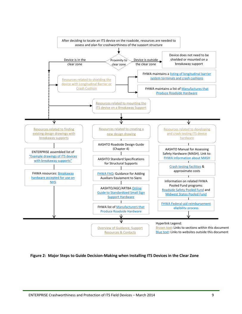
Figure 2 illustrates an overview of the major steps an agency may take to help guide decision-making
when deploying ITS devices in the roadway clear zone. In the sub-sections that follow, relevant
resources within each major step are provided.
The Manual on Uniform Traffic Control Devices (MUTCD) states that “Ground-mounted sign supports
shall be breakaway, yielding, or shielded with a longitudinal barrier or crash cushion if within the clear
zone.” Therefore, two options exist:
1) Option #1 - Shield the ITS device with a longitudinal barrier or crash cushion; or
2) Option #2 - Mount the ITS device on a breakaway support.
Section 3.2 provides resources for shielding ITS devices with longitudinal barriers or crash cushions.
Section 3.3 outlines options for mounting ITS devices on breakaway supports. Note that Chapter 4 of the
AASHTO Roadside Design Guide states that “The term breakaway support refers to all types of sign,
luminaire, and traffic signal supports that are designed to yield, fracture, or separate when impacted by
a vehicle. The release mechanism may be a slip plane, plastic hinge, fracture elements, or a combination
of them.” Therefore, for the purposes of this section, all types of breakaway supports, including yielding
and base-bending types, will be referred to as “breakaway supports.”
Section 3.4 provides a summary of general resources and contact information for information regarding
breakaway supports.
ENTERPRISE Crashworthiness and Protection of ITS Field Devices – March 2014 9
Figure 2: Major Steps to Guide Decision-Making when Installing ITS Devices in the Clear Zone
After deciding to locate an ITS device on the roadside, resources are needed to assess and plan for crashworthiness of the support structure
FHWA maintains a listing of longitudinal barrier system terminals and crash cushions
FHWA maintains a list of Manufactures that
Produce Roadside Hardware
Device does not need to be shielded or mounted on a
breakaway support
Device is outside the clear zone
Resources related to mounting the ITS device on a Breakaway Support
Resources related to shielding the device with Longitudinal Barrier or
Crash Cushion
Device is in the clear zone
Proximity to clear zone
Resources related to creating a
new design drawing
Resources related to developing and crash testing ITS device
hardware
AASHTO Roadside Design Guide (Chapter 4)
AASHTO Standard Specifications for Structural Supports
FHWA FAQ: Guidance for Adding
Auxiliary Equipment to Signs
AASHTO/AGC/ARTBA Online
Guide to Standardized Small Sign Support Hardware
FHWA list of Manufacturers that
Produce Roadside Hardware
Overview of Guidance, Support Resources & Contacts
Resources related to finding existing design drawings with
breakaway supports
ENTERPRISE assembled list of “Example drawings of ITS devices
with breakaway supports”
FHWA resources: Breakaway hardware accepted for use on
NHS
AASHTO Manual for Assessing Safety Hardware (MASH). Link to: FHWA Information about MASH
Crash testing facilities & approximate costs
Information on related FHWA
Pooled Fund programs: Roadside Safety Pooled Fund and
Midwest States Pooled Fund
FHWA Federal-aid reimbursement eligibility process
Hyperlink Legend: Brown text: Links to sections within this document Blue text: Links to websites outside this document
ENTERPRISE Crashworthiness and Protection of ITS Field Devices – March 2014 10
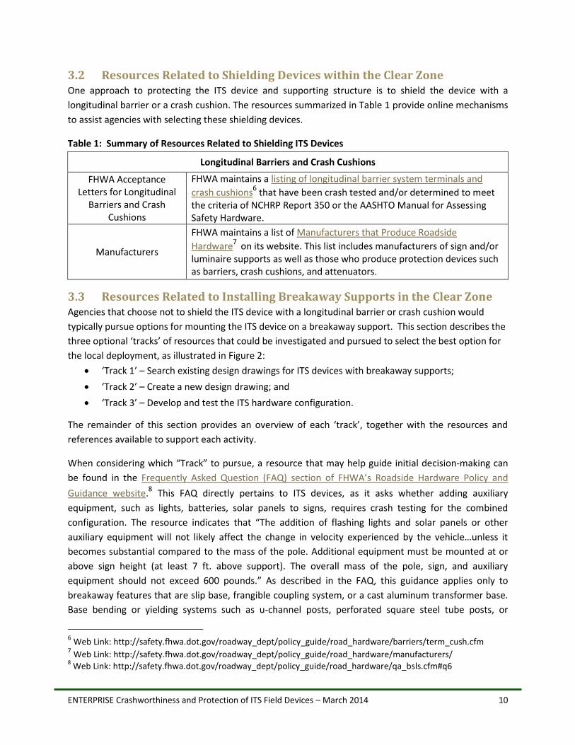
3.2 Resources Related to Shielding Devices within the Clear Zone One approach to protecting the ITS device and supporting structure is to shield the device with a
longitudinal barrier or a crash cushion. The resources summarized in Table 1 provide online mechanisms
to assist agencies with selecting these shielding devices.
Table 1: Summary of Resources Related to Shielding ITS Devices
Longitudinal Barriers and Crash Cushions
FHWA Acceptance Letters for Longitudinal
Barriers and Crash Cushions
FHWA maintains a listing of longitudinal barrier system terminals and
crash cushions6 that have been crash tested and/or determined to meet the criteria of NCHRP Report 350 or the AASHTO Manual for Assessing Safety Hardware.
Manufacturers
FHWA maintains a list of Manufacturers that Produce Roadside
Hardware7
on its website. This list includes manufacturers of sign and/or luminaire supports as well as those who produce protection devices such as barriers, crash cushions, and attenuators.
3.3 Resources Related to Installing Breakaway Supports in the Clear Zone Agencies that choose not to shield the ITS device with a longitudinal barrier or crash cushion would
typically pursue options for mounting the ITS device on a breakaway support. This section describes the
three optional ‘tracks’ of resources that could be investigated and pursued to select the best option for
the local deployment, as illustrated in Figure 2:
‘Track 1’ – Search existing design drawings for ITS devices with breakaway supports;
‘Track 2’ – Create a new design drawing; and
‘Track 3’ – Develop and test the ITS hardware configuration.
The remainder of this section provides an overview of each ‘track’, together with the resources and
references available to support each activity.
When considering which “Track” to pursue, a resource that may help guide initial decision-making can
be found in the Frequently Asked Question (FAQ) section of FHWA’s Roadside Hardware Policy and
Guidance website.8 This FAQ directly pertains to ITS devices, as it asks whether adding auxiliary
equipment, such as lights, batteries, solar panels to signs, requires crash testing for the combined
configuration. The resource indicates that “The addition of flashing lights and solar panels or other
auxiliary equipment will not likely affect the change in velocity experienced by the vehicle…unless it
becomes substantial compared to the mass of the pole. Additional equipment must be mounted at or
above sign height (at least 7 ft. above support). The overall mass of the pole, sign, and auxiliary
equipment should not exceed 600 pounds.” As described in the FAQ, this guidance applies only to
breakaway features that are slip base, frangible coupling system, or a cast aluminum transformer base.
Base bending or yielding systems such as u-channel posts, perforated square steel tube posts, or
6 Web Link: http://safety.fhwa.dot.gov/roadway_dept/policy_guide/road_hardware/barriers/term_cush.cfm 7 Web Link: http://safety.fhwa.dot.gov/roadway_dept/policy_guide/road_hardware/manufacturers/ 8 Web Link: http://safety.fhwa.dot.gov/roadway_dept/policy_guide/road_hardware/qa_bsls.cfm#q6
ENTERPRISE Crashworthiness and Protection of ITS Field Devices – March 2014 11
composite posts require full scale crash testing. The AASHTO Roadside Design Guide should be
referenced for specific guidance related to adding auxiliary equipment to sign or luminaire supports.
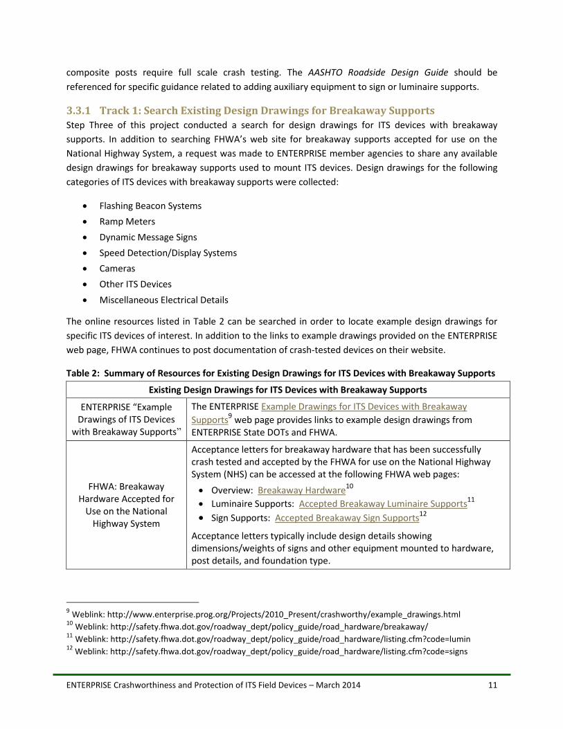
3.3.1 Track 1: Search Existing Design Drawings for Breakaway Supports
Step Three of this project conducted a search for design drawings for ITS devices with breakaway
supports. In addition to searching FHWA’s web site for breakaway supports accepted for use on the
National Highway System, a request was made to ENTERPRISE member agencies to share any available
design drawings for breakaway supports used to mount ITS devices. Design drawings for the following
categories of ITS devices with breakaway supports were collected:
Flashing Beacon Systems
Ramp Meters
Dynamic Message Signs
Speed Detection/Display Systems
Cameras
Other ITS Devices
Miscellaneous Electrical Details
The online resources listed in Table 2 can be searched in order to locate example design drawings for
specific ITS devices of interest. In addition to the links to example drawings provided on the ENTERPRISE
web page, FHWA continues to post documentation of crash-tested devices on their website.
Table 2: Summary of Resources for Existing Design Drawings for ITS Devices with Breakaway Supports
Existing Design Drawings for ITS Devices with Breakaway Supports
ENTERPRISE “Example Drawings of ITS Devices
with Breakaway Supports”
The ENTERPRISE Example Drawings for ITS Devices with Breakaway
Supports9 web page provides links to example design drawings from
ENTERPRISE State DOTs and FHWA.
FHWA: Breakaway Hardware Accepted for
Use on the National Highway System
Acceptance letters for breakaway hardware that has been successfully crash tested and accepted by the FHWA for use on the National Highway System (NHS) can be accessed at the following FHWA web pages:
Overview: Breakaway Hardware10
Luminaire Supports: Accepted Breakaway Luminaire Supports11
Sign Supports: Accepted Breakaway Sign Supports12
Acceptance letters typically include design details showing dimensions/weights of signs and other equipment mounted to hardware, post details, and foundation type.
9 Weblink: http://www.enterprise.prog.org/Projects/2010_Present/crashworthy/example_drawings.html 10 Weblink: http://safety.fhwa.dot.gov/roadway_dept/policy_guide/road_hardware/breakaway/ 11 Weblink: http://safety.fhwa.dot.gov/roadway_dept/policy_guide/road_hardware/listing.cfm?code=lumin 12
Weblink: http://safety.fhwa.dot.gov/roadway_dept/policy_guide/road_hardware/listing.cfm?code=signs
ENTERPRISE Crashworthiness and Protection of ITS Field Devices – March 2014 12
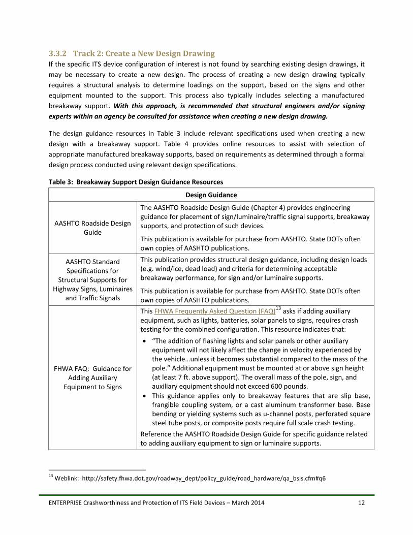
3.3.2 Track 2: Create a New Design Drawing
If the specific ITS device configuration of interest is not found by searching existing design drawings, it
may be necessary to create a new design. The process of creating a new design drawing typically
requires a structural analysis to determine loadings on the support, based on the signs and other
equipment mounted to the support. This process also typically includes selecting a manufactured
breakaway support. With this approach, is recommended that structural engineers and/or signing
experts within an agency be consulted for assistance when creating a new design drawing.
The design guidance resources in Table 3 include relevant specifications used when creating a new
design with a breakaway support. Table 4 provides online resources to assist with selection of
appropriate manufactured breakaway supports, based on requirements as determined through a formal
design process conducted using relevant design specifications.
Table 3: Breakaway Support Design Guidance Resources
Design Guidance
AASHTO Roadside Design Guide
The AASHTO Roadside Design Guide (Chapter 4) provides engineering guidance for placement of sign/luminaire/traffic signal supports, breakaway supports, and protection of such devices.
This publication is available for purchase from AASHTO. State DOTs often own copies of AASHTO publications.
AASHTO Standard Specifications for
Structural Supports for Highway Signs, Luminaires
and Traffic Signals
This publication provides structural design guidance, including design loads (e.g. wind/ice, dead load) and criteria for determining acceptable breakaway performance, for sign and/or luminaire supports.
This publication is available for purchase from AASHTO. State DOTs often own copies of AASHTO publications.
FHWA FAQ: Guidance for Adding Auxiliary
Equipment to Signs
This FHWA Frequently Asked Question (FAQ)13 asks if adding auxiliary equipment, such as lights, batteries, solar panels to signs, requires crash testing for the combined configuration. This resource indicates that:
“The addition of flashing lights and solar panels or other auxiliary equipment will not likely affect the change in velocity experienced by the vehicle…unless it becomes substantial compared to the mass of the pole.” Additional equipment must be mounted at or above sign height (at least 7 ft. above support). The overall mass of the pole, sign, and auxiliary equipment should not exceed 600 pounds.
This guidance applies only to breakaway features that are slip base, frangible coupling system, or a cast aluminum transformer base. Base bending or yielding systems such as u-channel posts, perforated square steel tube posts, or composite posts require full scale crash testing.
Reference the AASHTO Roadside Design Guide for specific guidance related to adding auxiliary equipment to sign or luminaire supports.
13
Weblink: http://safety.fhwa.dot.gov/roadway_dept/policy_guide/road_hardware/qa_bsls.cfm#q6
ENTERPRISE Crashworthiness and Protection of ITS Field Devices – March 2014 13
Table 4: Resources for Locating Manufactured Breakaway Supports
Manufactured Breakaway Supports
AASHTO/AGC/ARTBA Online Guide To
Standardized Small Sign Support Hardware
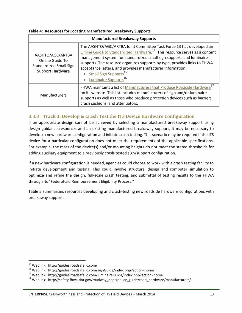
The AASHTO/AGC/ARTBA Joint Committee Task Force 13 has developed an
Online Guide to Standardized Hardware.14 This resource serves as a content
management system for standardized small sign supports and luminaire supports. The resource organizes supports by type, provides links to FHWA acceptance letters, and provides manufacturer information.
Small Sign Supports15
Luminaire Supports16
Manufacturers
FHWA maintains a list of Manufacturers that Produce Roadside Hardware17 on its website. This list includes manufacturers of sign and/or luminaire supports as well as those who produce protection devices such as barriers, crash cushions, and attenuators.
3.3.3 Track 3: Develop & Crash Test the ITS Device Hardware Configuration
If an appropriate design cannot be achieved by selecting a manufactured breakaway support using
design guidance resources and an existing manufactured breakaway support, it may be necessary to
develop a new hardware configuration and initiate crash testing. This scenario may be required if the ITS
device for a particular configuration does not meet the requirements of the applicable specifications.
For example, the mass of the device(s) and/or mounting heights do not meet the stated thresholds for
adding auxiliary equipment to a previously crash-tested sign/support configuration.
If a new hardware configuration is needed, agencies could choose to work with a crash testing facility to
initiate development and testing. This could involve structural design and computer simulation to
optimize and refine the design, full-scale crash testing, and submittal of testing results to the FHWA
through its “Federal-aid Reimbursement Eligibility Process.”
Table 5 summarizes resources developing and crash-testing new roadside hardware configurations with
breakaway supports.
14
Weblink: http://guides.roadsafellc.com/ 15
Weblink: http://guides.roadsafellc.com/signGuide/index.php?action=home 16
Weblink: http://guides.roadsafellc.com/luminaireGuide/index.php?action=home 17
Weblink: http://safety.fhwa.dot.gov/roadway_dept/policy_guide/road_hardware/manufacturers/
ENTERPRISE Crashworthiness and Protection of ITS Field Devices – March 2014 14
Table 5: Resources for Developing and Testing New Roadside Hardware with Breakaway Supports
New Hardware Configurations: Development and Crash Testing
AASHTO Manual for Assessing Safety
Hardware (MASH)
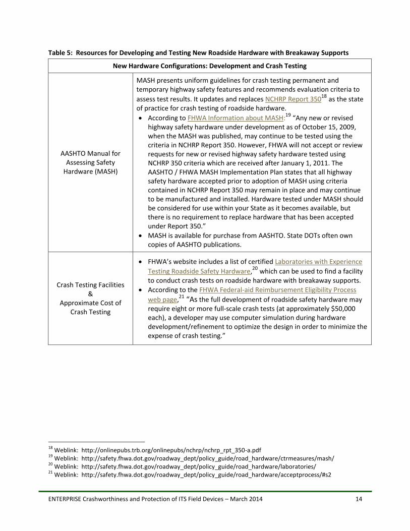
MASH presents uniform guidelines for crash testing permanent and temporary highway safety features and recommends evaluation criteria to
assess test results. It updates and replaces NCHRP Report 35018 as the state
of practice for crash testing of roadside hardware.
According to FHWA Information about MASH:19 “Any new or revised highway safety hardware under development as of October 15, 2009, when the MASH was published, may continue to be tested using the criteria in NCHRP Report 350. However, FHWA will not accept or review requests for new or revised highway safety hardware tested using NCHRP 350 criteria which are received after January 1, 2011. The AASHTO / FHWA MASH Implementation Plan states that all highway safety hardware accepted prior to adoption of MASH using criteria contained in NCHRP Report 350 may remain in place and may continue to be manufactured and installed. Hardware tested under MASH should be considered for use within your State as it becomes available, but there is no requirement to replace hardware that has been accepted under Report 350.”
MASH is available for purchase from AASHTO. State DOTs often own copies of AASHTO publications.
Crash Testing Facilities &
Approximate Cost of Crash Testing
FHWA’s website includes a list of certified Laboratories with Experience
Testing Roadside Safety Hardware,20 which can be used to find a facility
to conduct crash tests on roadside hardware with breakaway supports.
According to the FHWA Federal-aid Reimbursement Eligibility Process
web page,21 “As the full development of roadside safety hardware may require eight or more full-scale crash tests (at approximately $50,000 each), a developer may use computer simulation during hardware development/refinement to optimize the design in order to minimize the expense of crash testing.”
18
Weblink: http://onlinepubs.trb.org/onlinepubs/nchrp/nchrp_rpt_350-a.pdf 19
Weblink: http://safety.fhwa.dot.gov/roadway_dept/policy_guide/road_hardware/ctrmeasures/mash/ 20
Weblink: http://safety.fhwa.dot.gov/roadway_dept/policy_guide/road_hardware/laboratories/ 21
Weblink: http://safety.fhwa.dot.gov/roadway_dept/policy_guide/road_hardware/acceptprocess/#s2
ENTERPRISE Crashworthiness and Protection of ITS Field Devices – March 2014 15
New Hardware Configurations: Development and Crash Testing
FHWA Pooled Fund Programs
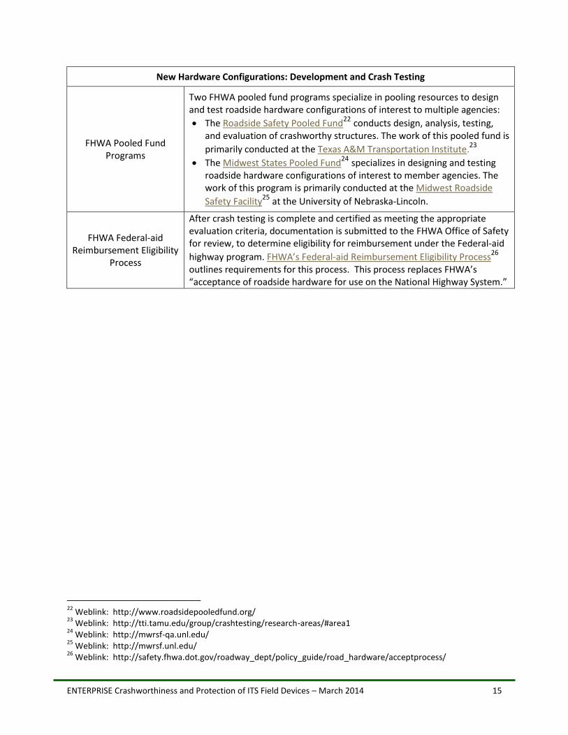
Two FHWA pooled fund programs specialize in pooling resources to design and test roadside hardware configurations of interest to multiple agencies:
The Roadside Safety Pooled Fund22 conducts design, analysis, testing,
and evaluation of crashworthy structures. The work of this pooled fund is
primarily conducted at the Texas A&M Transportation Institute.23
The Midwest States Pooled Fund24 specializes in designing and testing
roadside hardware configurations of interest to member agencies. The work of this program is primarily conducted at the Midwest Roadside
Safety Facility25
at the University of Nebraska-Lincoln.
FHWA Federal-aid Reimbursement Eligibility
Process
After crash testing is complete and certified as meeting the appropriate evaluation criteria, documentation is submitted to the FHWA Office of Safety for review, to determine eligibility for reimbursement under the Federal-aid
highway program. FHWA’s Federal-aid Reimbursement Eligibility Process26
outlines requirements for this process. This process replaces FHWA’s “acceptance of roadside hardware for use on the National Highway System.”
22
Weblink: http://www.roadsidepooledfund.org/ 23
Weblink: http://tti.tamu.edu/group/crashtesting/research-areas/#area1 24
Weblink: http://mwrsf-qa.unl.edu/ 25
Weblink: http://mwrsf.unl.edu/ 26
Weblink: http://safety.fhwa.dot.gov/roadway_dept/policy_guide/road_hardware/acceptprocess/
ENTERPRISE Crashworthiness and Protection of ITS Field Devices – March 2014 16
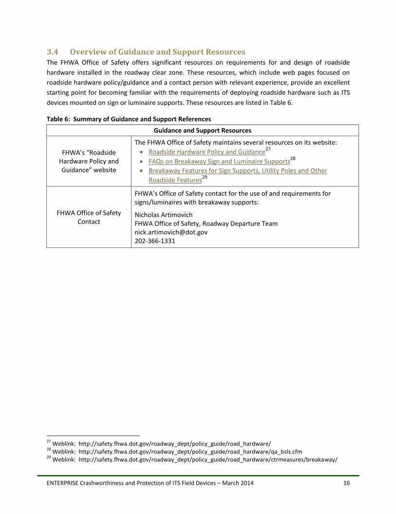
3.4 Overview of Guidance and Support Resources The FHWA Office of Safety offers significant resources on requirements for and design of roadside
hardware installed in the roadway clear zone. These resources, which include web pages focused on
roadside hardware policy/guidance and a contact person with relevant experience, provide an excellent
starting point for becoming familiar with the requirements of deploying roadside hardware such as ITS
devices mounted on sign or luminaire supports. These resources are listed in Table 6.
Table 6: Summary of Guidance and Support References
Guidance and Support Resources
FHWA’s “Roadside Hardware Policy and Guidance” website
The FHWA Office of Safety maintains several resources on its website:
Roadside Hardware Policy and Guidance27
FAQs on Breakaway Sign and Luminaire Supports28
Breakaway Features for Sign Supports, Utility Poles and Other
Roadside Features29
FHWA Office of Safety Contact
FHWA’s Office of Safety contact for the use of and requirements for signs/luminaires with breakaway supports:
Nicholas Artimovich FHWA Office of Safety, Roadway Departure Team [email protected] 202-366-1331
27
Weblink: http://safety.fhwa.dot.gov/roadway_dept/policy_guide/road_hardware/ 28
Weblink: http://safety.fhwa.dot.gov/roadway_dept/policy_guide/road_hardware/qa_bsls.cfm 29
Weblink: http://safety.fhwa.dot.gov/roadway_dept/policy_guide/road_hardware/ctrmeasures/breakaway/
ENTERPRISE Crashworthiness and Protection of ITS Field Devices – March 2014 17
4.0 Conclusions
This project produced a number of resources that agencies can use to help navigate and guide decision
making for assessing crashworthiness and deploying ITS devices in the roadway clear zone. Several
design drawings for specific ITS device configurations with breakaway supports were located and
summarized for easy reference by ENTERPRISE members. In addition, a summary of options and
relevant resources for shielding or installing ITS devices in the clear zone was compiled. These options
and resources are predominately structured around design principles contained in AASHTO specification
and guidance provided by the FHWA.
A summary of the project and its results were presented at the February 2014 ENTERPRISE Board
meeting. ENTERPRISE Board members were asked whether there was a need/role for an additional
future ENTERPRISE project related to crashworthiness of ITS devices (e.g. one example of a candidate of
a future project might involve collaboration with one or more crash testing facilities to test some
frequently used combinations of ITS devices that all members might benefit from). Feedback from Board
members indicated that the final products (online links to ITS device drawings and the summary of
resources) will serve as helpful tools for designers, and that additional projects on this topic were not
needed at this time.
ENTERPRISE Crashworthiness and Protection of ITS Field Devices – March 2014 18
Appendix A: Example Design Drawings for ITS Devices with Breakaway
Supports
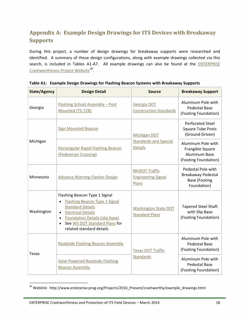
During this project, a number of design drawings for breakaway supports were researched and
identified. A summary of these design configurations, along with example drawings collected via this
search, is included in Tables A1-A7. All example drawings can also be found at the ENTERPRISE
Crashworthiness Project Website30
.
Table A1: Example Design Drawings for Flashing Beacon Systems with Breakaway Supports
State/Agency Design Detail Source Breakaway Support
Georgia Flashing School Assembly – Post
Mounted (TS-12B)
Georgia DOT
Construction Standards
Aluminum Pole with Pedestal Base
(Footing Foundation)
Michigan
Sign Mounted Beacon
Michigan DOT
Standards and Special
Details
Perforated Steel Square Tube Posts (Ground-Driven)
Rectangular Rapid Flashing Beacon
(Pedestrian Crossing)
Aluminum Pole with Frangible Square Aluminum Base
(Footing Foundation)
Minnesota Advance Warning Flasher Design
MnDOT Traffic
Engineering Signal
Plans
Pedestal Pole with Breakaway Pedestal
Base (Footing Foundation)
Washington
Flashing Beacon Type 1 Signal
Flashing Beacon Type 1 Signal Standard Details
Electrical Details Foundation Details (slip-base) See WS DOT Standard Plans for
related standard details
Washington State DOT
Standard Plans
Tapered Steel Shaft with Slip Base
(Footing Foundation)
Texas
Roadside Flashing Beacon Assembly
Texas DOT Traffic
Standards
Aluminum Pole with Pedestal Base
(Footing Foundation)
Solar Powered Roadside Flashing
Beacon Assembly
Aluminum Pole with Pedestal Base
(Footing Foundation)
30
Weblink: http://www.enterprise.prog.org/Projects/2010_Present/crashworthy/example_drawings.html

ENTERPRISE Crashworthiness and Protection of ITS Field Devices – March 2014 19
State/Agency Design Detail Source Breakaway Support
FHWA
Flashing Light Warning Apparatus FHWA SS-112 Acceptance Letter
Breakaway Hardware
Accepted for Use on
the National Highway
System
Aluminum Pole with Cast Aluminum
Breakaway Transformer Base
(Footing Foundation) OR U-Channel Steel
Posts with Lap Splice Breakaway System
(Ground-Driven)
School Zone Flashing Beacon System SS-161 Acceptance Letter
Galvanized Steel Pole with Pelco 5300
Series Breakaway Base (Foundation type not shown)
Table A2: Example Design Drawings for Ramp Meter Systems with Breakaway Supports
State/Agency Design Detail Source Breakaway Support
Georgia Ramp Meter Signal Support
Structures Detail (ITS-54)
Georgia DOT Construction
Standards
Aluminum Pole with Pedestal Base (Footing
Foundation)
Minnesota
Ramp Meter (one way) Detail with Standard Plate 8122F Pedestal and Pedestal Base (for Traffic Control Signals Support)
MnDOT ITS Project Management Design Manual and MnDOT Standard Plans
Aluminum Pole with Pedestal Base (Footing
Foundation)
Washington
Ramp Meter Signal: Ramp Meter Standard Details
Ramp Meter Electrical Details
Foundation Details (slip-base)
See WS DOT Standard Plans for related standard details
Washington State DOT
Standard Plans
Tapered Steel Shaft with Slip Base (Footing
Foundation)
ENTERPRISE Crashworthiness and Protection of ITS Field Devices – March 2014 20
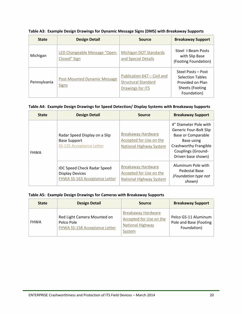
Table A3: Example Design Drawings for Dynamic Message Signs (DMS) with Breakaway Supports
State Design Detail Source Breakaway Support
Michigan LED Changeable Message “Open-
Closed” Sign
Michigan DOT Standards
and Special Details
Steel I-Beam Posts with Slip Base
(Footing Foundation)
Pennsylvania Post-Mounted Dynamic Message
Signs
Publication 647 – Civil and
Structural Standard
Drawings for ITS
Steel Posts – Post Selection Tables Provided on Plan Sheets (Footing
Foundation)
Table A4: Example Design Drawings for Speed Detection/ Display Systems with Breakaway Supports
State Design Detail Source Breakaway Support
FHWA
Radar Speed Display on a Slip Base Support SS-135 Acceptance Letter
Breakaway Hardware
Accepted for Use on the
National Highway System
4” Diameter Pole with Generic Four-Bolt Slip Base or Comparable
Base using Crashworthy Frangible
Couplings (Ground-Driven base shown)
IDC Speed Check Radar Speed Display Devices FHWA SS-163 Acceptance Letter
Breakaway Hardware
Accepted for Use on the
National Highway System
Aluminum Pole with Pedestal Base
(Foundation type not shown)
Table A5: Example Design Drawings for Cameras with Breakaway Supports
State Design Detail Source Breakaway Support
FHWA Red Light Camera Mounted on Pelco Pole FHWA SS-158 Acceptance Letter
Breakaway Hardware
Accepted for Use on the
National Highway
System
Pelco GS-11 Aluminum Pole and Base (Footing
Foundation)

ENTERPRISE Crashworthiness and Protection of ITS Field Devices – March 2014 21
Table A6: Example Design Drawings for Other ITS Devices with Breakaway Supports
State Design Detail Source Breakaway Support
Idaho Non-Invasive Pavement Sensor Pole & Foundation Detail I-7-C
Robert Koberlein [email protected]
Steel Pole with Slip Base (Footing Foundation)
Table A7: Example Design Drawings for Electrical Details used with Breakaway Supports
State Design Detail Source Breakaway Support
Idaho Dynamic Message Signs Breakaway Electrical Details
Robert Koberlein [email protected]
N/A
Pennsylvania Highway Advisory Radio System Electrical Details
Publication 647 Civil and Structural Standard Drawings for ITS
N/A