Embed Size (px)
Citation preview

Research ArticleA Finite Segment Method for Skewed Box Girder Analysis
Xingwei Xue Jiawei Wu Junlong Zhou and Hongnan Li
School of Civil Engineering Shenyang Jianzhu University Shenyang 110168 China
Correspondence should be addressed to Junlong Zhou 13889341820163com
Received 21 November 2017 Accepted 9 January 2018 Published 13 February 2018
Academic Editor Roman Lewandowski
Copyright copy 2018 Xingwei Xue et al This is an open access article distributed under the Creative Commons Attribution Licensewhich permits unrestricted use distribution and reproduction in any medium provided the original work is properly cited
A finite segment method is presented to analyze the mechanical behavior of skewed box girders By modeling the top and bottomplates of the segments with skew plate beam element under an inclined coordinate system and the webs with normal plate beamelement a spatial elastic displacement model for skewed box girder is constructed which can satisfy the compatibility condition atthe corners of the cross section for box girdersThe formulation of the finite segment is developed based on the variational principleThe major advantage of the proposed approach in comparison with the finite element method is that it can simplify a three-dimensional structure into a one-dimensional structure for structural analysis which results in significant saving in computationaltimes At last the accuracy and efficiency of the proposed finite segment method are verified by a model test
1 Introduction
The continued economic development and increasing invest-ment in infrastructure in China has resulted in a markedimprovement in construction standards for transportationnetworks throughout the countryThis investment and devel-opment include the increased design and implementation ofhigh-speed rail lines especially in the more populous easternportion of the country [1] Skew bridges are commonlyused on high-speed railway lines due to their followingadvantages (a) maintaining harmony with the surroundingbuildings and environment by requiring less land spacefor the new structure (b) reducing resistance to flow forpiers located in the water and (c) meeting high-speed railperformance demands Compared with a bridge having anorthogonal substructure the behavior of skewed bridges ismore complicated due to torsional effects that result from theskew angle [2]
During the past few decades experimental and com-putational studies of skewed highway bridges have beenperformed [3ndash6] Scordelis et al [7] presented the theoreticaland experimental results of a 45∘ skew two-span four-cellreinforced concrete box girder bridge model with a 1 282scale Results are given for reactions deflections strainsand moments due to working stress point loads applied
before and after overload stress levels in the bridge Evansand Rowlands [8] carried out experimental and theoreticalinvestigations of the behavior of single-cell single-spanbox girders on skew supports The behavior of bridge wasanalyzed by the FEM The effect of the skew angle on thebehavior of bridge was discussed Meng et al [9] describedan analytical and experimental study of a skewed bridgemodel The FE analyses (FEA) were performed using thecommercial software SAP2000 Good agreement betweenthe experimental and FEA results is obtained Meng andLiu [10] proposed a refined stick model for the preliminarydynamic analysis of skew bridges as well Badwan and Liang[11] presented an in-site static load test and a FEA on anexisting 60∘ skew three-span continuous steel girder bridgeThe measured bridge response under the test load was usedto develop and calibrate a FEM model by using ANSYSsoftware The calibrated FEM model was demonstrated thatit is realistic to predict the bridge response Menassa et al[12] reported that the effect of a skew angle on simple-span reinforced concrete bridges using FEM The commer-cial FE software SAP2000 was used to generate the three-dimensional finite element models The results show that theAASHTO Standard Specifications procedure overestimatedthe maximum longitudinal bending moment when a skewangle is larger than 20∘ Since conventional grillage methods
HindawiMathematical Problems in EngineeringVolume 2018 Article ID 2592613 13 pageshttpsdoiorg10115520182592613
2 Mathematical Problems in Engineering
x
wz
y
o u
v
(a) Isometric viewx
w
u
z
o
(b) Top view
Figure 1 Inclined coordinate system for the top and bottom plates
cannot account for some important structural actions of thin-walled box girders the Canadian Highway Bridge DesignCode (CHBDC) [13] as well as the American Association ofState Highway Transportation Officials (AASHTO) [14 15]has prohibited the use of the conventional grillage methodin the case of certain types of box girder bridges Due to alarge number of degrees of freedom needed a detailed three-dimensional FEAof box girders performed using commercialFE programs is too complex and time-consumingThereforeit is important to develop a practical FEM to reduce theamount of computational work for the analysis of the skewedbox girder bridges Finite segment method has been usedto simplify a three-dimensional thin-walled box girder intoa one-dimensional structure for curved box girder analysis[16] But until now such method used for skew box girderanalysis do not appear to be reported in the open literature
In this study by modeling the top and bottom platesof a skew box girder with skewed plate beam elementand the webs with normal plate beam element a spatialdisplacement field for a skewed box girder is constructedThedisplacement compatibilities of the subelements at cornersare met accordingly Skewed plate beam element representsthat the element is formulated under an inclined coordinatesystem while the normal plate beam element represents thatthe element is formulated under an orthogonal coordinatesystem The skewed box girder is discretized into finitesegmentswhichwere assembled by 4-plate beam subelementsalong the length of the girder To verify the accuracy of theproposed finite segment method (FSM) the results obtainedusing this approach were compared with the results obtainedby using ANSYS and the tested results from a modal test
2 Basic Formulae under InclinedCoordinate System
There is an inclined angle between the central line and thesupport line of the bridge Therefore an inclined coordinatesystem is chosen for the top and bottom plates of the skewedbox girder as shown in Figure 1
The inclined angle of the specific plates is 120572 the rela-tionships between the rectangular coordinates (119900119909119910119911) and theinclined coordinates (119900119906V119908) are
119909 = 119906 + 119908 cos120572119910 = V119911 = 119908 sin120572119906 = 119909 minus 119911119888119905119892120572V = 119910119908 = 119911
sin120572
(1)
where 119906 V and 119908 are the transverse (along the 119909 direction)vertical (along the 119910 direction) and longitudinal displace-ment (in the 119911 direction) of the top or bottom plate respec-tively Using the derivative principle of the multivariablefunctions there is
120597119908120597119911 = minus120597119908120597119906 119888119905119892120572 + 1sin120572 120597119908120597119908
120597119908120597119909 = 120597119908120597119906 120597119908120597119910 = 120597119908120597V 120597V120597119911 = minus cot120572 120597V120597119906 + 1
sin120572 120597V120597119908120597119906120597119911 = minus cot120572120597119906120597119906 + 1
sin120572 1205971199061205971199081205972V1205971199112 = cot2120572 1205972V1205971199062 minus 2 cot120572
sin120572 1205972V120597119906120597119908 + 1sin2120572 1205972V1205971199082
12059721199061205971199112 = cot212057212059721199061205971199062 minus 2 cot120572sin120572 1205972119906120597119906120597119908 + 1
sin2120572 12059721199061205971199082
(2)
Mathematical Problems in Engineering 3
h
b
xu
v y
wz
o
bu
blℎb
l
wul wuR
wll
RwlR
ul
uu
Figure 2 The cross-sectional displacement parameters of a single-cell skewed box girder
3 Displacement Model of the Cross Section
For convenience of illustration a single-cell skewed boxgirder is used as an example herein The cross-sectionaldisplacement parameters of a single-cell skewed box girderare shown in Figure 2 To establish the displacement modelof the spatial skewed box girder two assumptions based onVlasovrsquos thin-walled beam theory [17] are adopted in thispaper
(1) As the skewed box girder is discretized into severalskewed box girder segments along the length of bridgethe displacement compatibilities of these elements at thelocations of corners are satisfied
(2) The tensile and compressive deformations along thewidth and height directions of the four walls of the girder areignored
For each segment of the single-cell skewed box girderthe section displacement parameters include four longitudi-nal displacement parameters 119908119906119897 119908119906119877 119908119897119897 119908119897119877 for the fourcorners two transverse displacement parameters 119906119906 and 119906119897for the top and bottom plates and two vertical displacementparameters V119897 and V119877 for the left and right upper corners ofthe skewed box girder Hence there are eight independentdisplacement parameters for the cross section of the single-cell skewed box girder that is 119908119906119897 119908119906119877 119908119897119897 119908119897119877 119906119906 119906119897 V119897and V119877 The cross-sectional parameters of the skewed boxgirder segment are all defined in the rectangular coordinates(119900119909119910119911) that is the longitudinal displacements of the segment119908119906119897 119908119906119877 119908119897119897 and 119908119897119877 are along the axial 119911 direction notalong the skewed bridge axial line
4 Subelement Displacement Parameters
If the whole skewed beam segment of the skewed box girderis taken as one-beam element the segment can be discretizedinto wall subelements by which a suitable subelement dis-placement mode can be established According to the thin-walled beam theory [17] the displacement at the gravitycenter of the subelement cross section is equal to the averagevalue of displacements at the corresponding two nodes andthe subelement displacement parameters are determined bythe displacements at the two nodes
The nodal displacement parameters are shown in Fig-ure 3 The subelement displacement parameters are given asfollows
For the left web we have the followingThe transverse displacement (in the web plane) is
119906119891119897 = [119873 (119908)] 120575119906lowast119891119897 (3a)
The vertical displacement (out of the web plane) is
V119891119897 = [119873 (119908)] 120575Vlowast119891119897 (3b)
The longitudinal displacement (in the 119908 direction) is
119908119891119897 = [119872 (119908)] 120575119908lowast119891119897 (3c)
The torsional angle around axial 119908 is
120593119891119897 = [119872 (119908)] 120575120593lowast119891119897 (3d)
For the right web we have the followingThe transverse displacement (in the web plane) is
119906119891119877 = [119873 (119908)] 120575119906lowast119891119877 (4a)
The vertical displacement (out of the web plane) is
V119891119877 = [119873 (119908)] 120575Vlowast119891119877 (4b)
The longitudinal displacement (in the 119908 direction) is
119908119891119877 = [119872 (119908)] 120575119908lowast119891119877 (4c)
The torsional angle around axial 119908 is
120593119891119877 = [119872 (119908)] 120575120593lowast119891119877 (4d)
In these above equations [119873(119908)] and [119872(119908)] are cubicshape functionmatrix and linear shape functionmatrix about119908 respectively The detailed expressions are as follows
[119873 (119908)] = [1198731 (119908) 1198732 (119908) 1198733 (119908) 1198734 (119908)] (5a)
[119872 (119908)] = [1198721 (119908) 1198722 (119908)] (5b)
4 Mathematical Problems in Engineering
xu
v y
w
z
o
wflj
fljuflj
flj
wfli
fli ufli
fli
wuci
uci
uuci
uci
wucj
ucj
uucjucj
wlcj
lcj ulcj
lcj
wlci
lci ulci
lci
wfRi
fRi ufRi
fRi
wfRj
fRj ufRj
fRj
Figure 3 The nodal displacement parameters of the beam subelements
where
1198731 (119908) = 1 minus 3 (119908119897 )2 + 2 (119908119897 )
3 1198732 (119908) = 119908[1 minus 2119908119897 + (119908119897 )
2] 1198733 (119908) = (119908119897 )
2 [3 minus 2119908119897 ] 1198734 (119908) = 119908[minus119908119897 + (119908119897 )
2] 1198721 (119908) = 1 minus 119908119897 1198722 (119908) = 119908119897 120575119906lowast119891119897 = [119906119891119897119894 1199061015840119891119897119894 119906119891119897119895 1199061015840119891119897119895]119879 120575Vlowast119891119897 = [V119891119897119894 V1015840119891119897119894 V119891119897119895 V1015840119891119897119895]119879 120575119908lowast119891119897 = [119908119891119897119894 119908119891119897119895]119879 120575120593lowast119891119897 = [120593119891119897119894 120593119891119897119895]119879 120575119906lowast119891119877 = [119906119891119877119894 1199061015840119891119877119894 119906119891119877119895 1199061015840119891119877119895]119879 120575Vlowast119891119877 = [V119891119877119894 V1015840119891119877119894 V119891119877119895 V1015840119891119877119895]119879 120575119908lowast119891119877 = [119908119891119877119894 119908119891119877119895]119879 120575120593lowast119891119877 = [120593119891119877119894 120593119891119877119895]119879
(6)
For the top and bottom subelements because of theirskew geometry their displacement parameters are all definedrelative to the rectangular coordinate (119900119909119910119911) for conve-nience in expressing the stiffness matrices of the specific
subelements Hence the four nodal transverse displacements119906119906119888119894 119906119906119888119895 119906119897119888119894 119906119897119888119895 are along the119909direction the nodal verticaldisplacements V119906119888119894 V119906119888119895 V119897119888119894 V119897119888119895 are along the 119910 direction andthe longitudinal node displacements 119908119906119888119894 119908119906119888119895 119908119897119888119894 119908119897119888119895 arealong the 119911 direction as shown in Figure 3 The subelementdisplacement parameters are given as follows
For the top plate we have the followingThe transverse displacement (in the 119909 direction) is
119906119906119888 = [119873 (119908)] 120575119906lowast119906119888 (7a)
The vertical displacement (in the 119910 direction) is
V119906119888 = [119873 (119908)] 120575Vlowast119906119888 (7b)
The longitudinal displacement (in the 119911 direction) is119908119906119888 = [119872 (119908)] 120575119908lowast119906119888 (7c)
The torsional angle around axial 119911 is120593119906119888 = [119872 (119908)] 120575120593lowast119906119888 (7d)
For the bottom plate we have the followingThe transverse displacement (in the 119909 direction) is
119906119897119888 = [119873 (119908)] 120575119906lowast119897119888 (8a)
The vertical displacement (in the 119910 direction) is
V119897119888 = [119873 (119908)] 120575Vlowast119897119888 (8b)
The longitudinal displacement (in the 119911 direction) is119908119897119888 = [119872 (119908)] 120575119908lowast119897119888 (8c)
The torsional angle around axial 119911 is120593119897119888 = [119872 (119908)] 120575120593lowast119897119888 (8d)
Mathematical Problems in Engineering 5
where
120575119906lowast119906119888 = [119906119906119888119894 1199061015840119906119888119894 119906119906119888119895 1199061015840119906119888119895]119879 120575Vlowast119906119888 = [V119906119888119894 V1015840119906119888119894 V119906119888119895 V1015840119906119888119895]119879 120575119908lowast119906119888 = [119908119906119888119894 119908119906119888119895]119879 120575120593lowast119906119888 = [120593119906119888119894 120593119906119888119895]119879 120575119906lowast119897119888 = [119906119897119888119894 1199061015840119897119888119894 119906119897119888119895 1199061015840119897119888119895]119879 120575Vlowast119897119888 = [V119897119888119894 V1015840119897119888119894 V119897119888119895 V1015840119897119888119895]119879 120575119908lowast119897119888 = [119908119897119888119894 119908119897119888119895]119879 120575120593lowast119897119888 = [120593119897119888119894 120593119897119888119895]119879
(9)
5 Relationship between the DisplacementParameters of Subelement and the Section
According to the deformation compatibility conditionbetween the part and the whole the four walls of the skewedbox girder considered as subelement beams are connected atthe corners [16]
For the top plate there are
119906119906119888 = 1199061199061199061015840119906119888 = 1119887 (119908119906119897 minus 119908119906119877) V119906119888 = 12 (V119897 + V119877) V1015840119906119888 = 12 (V1015840119897 + V1015840119877) 119908119906119888 = 12 (119908119906119897 + 119908119906119877) 120593119906119888 = 1119887 (V119877 minus V119897)
(10)
For the bottom plate there are
119906119897119888 = 1199061198971199061015840119897119888 = 1119887119897 (119908119897119897 minus 119908119897119877) V119897119888 = 12 (V119897 + V119877) V1015840119897119888 = 12 (V1015840119897 + V1015840119877) 119908119897119888 = 12 (119908119897119897 + 119908119897119877) 120593119897119888 = 1119887119897 [V119877 minus V119897 + 2 (119906119897 minus 119906119906) 119905119892120573]
(11)
Sectional geometry and displacement parameters of theleft and right webs of the subelement are shown in Figure 4where section 1198601015840119861101584011986210158401198631015840 is normal to the center line of theskewed box girder In view of sectional geometry of skewedbox girder and the basic assumptions of the box girder thereare
V120572119891119897 = 12 [(119906119888 + 119906119897) sin120572 minus (119908119906119897 + 119908119897119897) cos120572] V120572119891119897 = 12 [2V119897 + (119906119906 minus 119906119897) 119905119892120573] 119906120572119891119897 = V119897 cos1205731 + (119906119906 sin120572 minus 119908119906119897 cos120572) sin1205731119908120572119891119897 = 12 [(119906119897 + 119906119906) cos120572 + (119908119906119897 + 119908119897119897) sin120572]
(12)
According to the geometric relationship in Figure 4 weobtained
119906119891119897 = 119906120572119891119897119908119891119897 = 119908120572119891119897V119891119897 = V120572119891119897 cos1205731 + V120572119897 sin1205731
(13)
Rearranging (12) and (13) gives the followingFor the left web
119906119891119897 = V119897 cos1205731 + (119906119906 sin120572 minus 119908119906119897 cos120572) sin12057311199061015840119891119897 = 1ℎ119887 ((119906119906 minus 119906119897) cos120572 + (119908119906119897 minus 119908119897119897) sin120572) V119891119897 = 12 cos1205731 ((119906119906 + 119906119897) sin120572 minus (119908119906119897 + 119908119897119897) cos120572)
minus 12 sin1205731 (2V119897 + (119906119906 minus 119906119897) 119905119892120573) V1015840119891119897 = (cos120573 + 119905119892120573 sin1205732119887119897 + sin120573ℎ )
sdot (119906119897 cos120572 + 119908119897119897 sin120572) minus (cos120573 + 119905119892120573 sin1205732119887119897 )times (119906119897 cos120572 + 119908119897119877 sin120572)+ (cos120573 + 119905119892120573 sin1205732119887 minus sin120573ℎ )sdot (119906119906 cos120572 + 119908119906119897 sin120572) minus (cos120573 + 119905119892120573 sin1205732119887 )sdot (119906119906 cos120572 + 119908119906119877 sin120572)
119908119891119897 = 12 ((119906119897 + 119906119906) cos 119886 + (119908119897119897 + 119908119906119897) sin120572) 120593119891119897 = 1ℎ (119906119906 sin120572 minus 119908119906119897 cos120572 minus 119906119897 sin120572 + 119908119897119897 cos120572)
(14)
6 Mathematical Problems in Engineering
A
C D
B
C
C
D
D
B
B
A
A
1
1
l
fl
ufl
wfl
R
fR
wfR
ufR
Figure 4 Sectional geometry and displacement parameters of the webs
For the right web
119906119891119877 = V119877 cos1205731 minus (119906119906 sin120572 minus 119908119906119877 cos120572) sin12057311199061015840119891119877 = 1ℎ119887 ((119906119906 minus 119906119897) cos120572 + (119908119906119877 minus 119908119897119877) sin120572) V119891119877
= 12 sin1205731 (2V119877 + (119906119897 minus 119906119906) 119905119892120573) + 12 cos1205731times ((119906119906 + 119906119897) sin120572 minus (119908119906119877 + 119908119897119877) cos120572)
V1015840119891119877
= 12119887 cos120573 (119906119906 cos120572 + 119908119906119897 sin120572)+ ( sin120573ℎ minus 12119887 cos120573) (119906119906 cos120572 + 119908119906119877 sin120572)+ 12119887119897 cos120573 (119906119897 cos120572 + 119908119897119897 sin120572)minus ( 12119887119897 cos120573 + sin120573ℎ ) (119906119897 cos120572 + 119908119897119877 sin120572)
119908119891119877 = 12 ((119906119897 + 119906119906) cos 119886 + (119908119897119877 + 119908119906119877) sin120572) 120593119891119877 = 1ℎ (119906119906 sin120572 minus 119908119906119877 cos120572 minus 119906119897 sin120572 + 119908119897119877 cos120572)
(15)
where 1205731 = arc 119905119892(((119887 minus 119887119897)2ℎ) sin120572)According to (10)ndash(15) each subelementrsquos displacement
parameter is related to the cross sectionrsquos displacementparameters as the following matrix form
119889119906 = 119860 119889 119889119897 = 119861 119889
119889119891119897 = 119862 119889
119889119891119877 = 119863 119889 (16)
where
119889119906 = [119908119906119888 119906119906119888 VV119888 120593119906119888 V1015840119906119888 1199061015840119906119888]119879 119889119897 = [119908119897119888 119906119897119888 V119897119888 120593119897119888 V1015840119897119888 1199061015840119897119888]119879
119889119891119897 = [119908119891119897 119906119891119897 V119891119897 120593119891119897 V1015840119891119897 1199061015840119891119897]119879 119889119891119877 = [119908119891119877 119906119891119877 V119891119877 120593119891119877 V1015840119891119877 1199061015840119891119877]119879
119889 = [119906119906 119906119897 V119897 V119877 119908119906119897 119908119906119877 119908119897119897 119908119897119877]119879
(17)
where 119860 119861 119862 and 119863 are the coefficient matrices that areobtained from (10)sim(15)6 Elastic Strain Energy of the Subelements
The transformation relationship between the inclined coordi-nate and the rectangular coordinate as defined in (1) and (2)was used to calculate the stiffness matrices
Once the displacementmodel of the subelements is giventhe displacements at arbitrary point of the subelement can bedetermined
On the top plate we have the followingThe transverse displacement (in the 119909 direction) is
119906119906 = [119873 (119908)] 120575119906lowast119906119888 minus V [119872 (119908)] 120575120593lowast119906119888 (18a)
The vertical displacement (in the 119910 direction) is
V119906 = [119873 (119908)] 120575Vlowast119906119888 minus 119906 [119872 (119908)] 120575120593lowast119906119888 (18b)
The longitudinal displacement (in the 119911 direction) is119908119906 = [119872 (119908)] 120575119908lowast119906119888 minus 119906 120597120597119911 ([119873 (119908)] 120575119906lowast119906119888)
minus V120597120597119911 ([119873 (119908)] 120575Vlowast119906119888)
(18c)
On the bottom plate we have the following
Mathematical Problems in Engineering 7
The transverse displacement (in the 119909 direction) is
119906119897 = [119873 (119908)] 120575119906lowast119897119888 minus V [119872 (119908)] 120575120593lowast119897119888 (19a)
The vertical displacement (in the 119910 direction) is
V119897 = [119873 (119908)] 120575Vlowast119897119888 + 119906 [119872 (119908)] 120575120593lowast119897119888 (19b)
The longitudinal displacement (in the 119911 direction) is119908119897 = [119872 (119908)] 120575119908lowast119897119888 minus 119906 120597120597119911 ([119873 (119908)] 120575119906lowast119897119888)
minus V120597120597119911 ([119873 (119908)] 120575Vlowast119897119888)
(19c)
Based on (1) and (2) the strain-displacement relationshipof the top plate can be written as
120576119906119911119911 = 120597119908119906120597119911= 1sin120572 [1198721015840 (119908)] 120575119908lowast119906119888+ cos120572sin2120572 [1198731015840 (119908)] 120575119906lowast119906119888
minus 119906sin2120572 [11987310158401015840 (119908)] 120575119906lowast119906119888
minus Vsin2120572 [11987310158401015840 (119908)] 120575Vlowast119906119888
120574119906119909119911 = 120597119908119906120597119909 + 120597119906119906120597119911 = minus Vsin120572 [1198721015840 (119908)] 120575120593lowast119906119888
120574119906119910119911 = 120597119908119906120597119910 + 120597V119906120597119911= minus cot120572 [119872 (119908)] 120575120593lowast119906119888
+ 119906sin120572 [1198721015840 (119908)] 120575120593lowast119906119888
(20)
Similarly the strain-displacement relationship of the bottomplate can be written as
120576119897119911119911 = 120597119908119897120597119911= 1sin120572 [1198721015840 (119908)] 120575119908lowast119897119888 + cos120572
sin2120572 [1198731015840 (119908)] 120575119906lowast119897119888minus 119906sin2120572 [11987310158401015840 (119908)] 120575119906lowast119897119888
minus Vsin2120572 [11987310158401015840 (119908)] 120575Vlowast119897119888
120574119897119909119911 = 120597119908119897120597119909 + 120597119906119897120597119911 = minus Vsin120572 [1198721015840 (119908)] 120575120593lowast119897119888
120574119897119910119911 = 120597119908119897120597119910 + 120597V119897120597119911= minus cot120572 [119872 (119908)] 120575120593lowast119897119888 + 119906
sin120572 [1198721015840 (119908)] 120575120593lowast119897119888 (21)
Thus the elastic strain energy of the top plate is
120587119906 = 12 intΩ119906
119864 (120576119906119911119911)2 119889Ω + 12 intΩ119906
119866 (120574119906119909119911)2 119889Ω+ 12 intΩ119906
119866(120574119906119910119911)2 119889Ω= 12 [120575119908lowast119906119888119879 120575119906lowast119906119888119879 120575Vlowast119906119888119879 120575120593lowast119906119888119879] [119870119879]
times [120575119908lowast119906119888119879 120575119906lowast119906119888119879 120575Vlowast119906119888119879 120575120593lowast119906119888119879]119879
(22)
where [119870119879] = [119870119894119895119879]4 times 4 (119894 119895 = 1 2 3 4) is the subelementrsquosstiffness matrix of the top plate Substituting (1) (2) (18a)(18b) and (18c) into (22) the stiffness matrix [119870119879] can beobtained
Similarly the elastic strain energy of the bottom plate canalso be obtained The shape of the webs has no difference incomparison with conventional beam Therefore the expres-sion of the elastic strain energy of webs can be written as
120587119891119897 = 12 [119889119891119897119894119879 119889119891119897119895119879 [119870119891119897] [119889119891119897119894119879 119889119891119897119895119879]119879] 120587119891119877
= 12 [119889119891119877119894119879 119889119891119877119895119879 [119870119891119877] [119889119891119877119894119879 119889119891119877119895119879]119879] (23)
7 Establishment of SegmentEquilibrium Equation
The total elastic strain energy of the skewed box girdersegment which consists of those of its subelements is givenas
120587 = 120587119906 + 120587119897 + 120587119891119897 + 120587119891119877 minus 119865119890119879 [119889119894119879 119889119895119879]119890119879 (24)
where120587119906 120587119897 120587119891119897 and120587119891119877 are the elastic strain energies of thetop plate the bottom plate the left web and the right webrespectively and the last item of the right-hand side is thework done by external force 119865119890119879 is the vector of nodal forceany forces acted not at the corners of the element should betransformed to the corners according to the shape functions[18]
Rearranging [120575119908lowast119906119888119879 120575119906lowast119906119888119879 120575Vlowast119906119888119879 120575120593lowast119906119888119879] into
[120575119906119894119879 119889119906119895119879] and [120575119908lowast119906119888119879 120575119906lowast119906119888119879 120575Vlowast119906119888119879 120575120593lowast119906119888119879]119879into [119889119906119894119879 119889119906119895119879]119879 gives the elastic strain energy of thetop and bottom plates as
120587119906 = 12 [120575119908lowast119906119888119879 120575119906lowast119906119888119879 120575Vlowast119906119888119879 120575120593lowast119906119888119879] times [119870119906]times [120575119908lowast119906119888119879 120575119906lowast119906119888119879 120575Vlowast119906119888119879 120575120593lowast119906119888119879]119879
8 Mathematical Problems in Engineering
= 12 [119889119906119894119879 119889119906119895119879] times [119870119906]times [119889119906119894119879 119889119906119895119879]119879
120587119897 = 12 [120575119908lowast119906119897119879 120575119906lowast119906119897119879 120575Vlowast119906119897119879 120575120593lowast119906119897119879] times [119870119897]times [120575119908lowast119906119897119879 120575119906lowast119906119897119879 120575Vlowast119906119897119879 120575120593lowast119906119897119879]119879
= 12 [119889119897119894119879 119889119897119895119879] times [119870119897] times [119889119897119894119879 119889119897119895119879]119879 (25)
Substituting (23) (25) into (24) gives
120587 = 12 [119889119906119894119879 119889119906119895119879] [119870119906] [119889119906119894119879 119889119906119895119879]119879 + 12sdot [119889119897119894119879 119889119897119895119879] [119870119897] [119889119897119894119879 119889119897119895119879]119879 + 12sdot [119889119891119897119894119879 119889119891119897119895119879] [119870119891119897] [119889119891119897119894119879 119889119891119897119895119879]119879
+ 12 [119889119891119877119894119879 119889119891119877119895119879] [119870119891119877]sdot [119889119891119877119894119879 119889119891119877119895119879]119879 minus 119865119890119879 [119889119894119879 119889119895119879]119879
(26)
Substituting (16) into (26) and applying the variation princi-ple give
([119860 00 119860]
119879 [119870119906] [119860 00 119860] + [119861 0
0 119861]119879 [119870119897] [119861 0
0 119861]
+ [119862 00 119862]
119879 [119870119891119897] [119862 00 119862]
+ [119863 00 119863]119879 [119870119891119877] [119863 0
0 119863])119889119894119889119894 = 119865119890
(27)
We constructed the following equations
120575119890 = [119889119894119879 119889119895119879]119879 (28a)
[119870]119890 = ([119860 00 119860]
119879 [119870119906] [119860 00 119860]
+ [119861 00 119861]
119879 [119870119897] [119861 00 119861]
+ [119862 00 119862]
119879 [119870119891119897] [119862 00 119862]
+ [119863 00 119863]119879 [119870119891119877] [119863 0
0 119863])
(28b)
So (27) can rewritten as
[119870]119890 120575119890 = 119865119890 (29)
This is the equilibrium equation of the segment where[119870119906] [119870119897] [119870119891119897] and [119870119891119877] are the subelementrsquos stiffnessmatrices of the top plate the bottom plate the left web andthe right web respectively [119870119906] and [119870119897] can be obtainedby rearranging the cross sectionrsquos displacement parametersinto (21) The form of [119870119891119897] and [119870119891119877] is same as that ofthe stiffness matrix of the conventional spatial beam elementBy using the same assembling method as the conventionalfinite element method the global stiffness matrices andequilibrium equation can be established and solved
8 Examples
81 Model Bridge Description A three-span continuous pre-stressed reinforced concrete skewed box girder bridge wastested by He et al [1] The skew angle of the box girder is 45∘and the bridge spans are 50 + 875 + 50mThe widths of themodel girder flanges were 165m at the top and 085m at thebottom The bridge height at mid-span of the main span was0375m and at the piers the height was 0625mThe top flangethickness varied between 40mm and 77mm the bottomflange thickness varied between 70mm and 90mm and theweb thickness was 100mm except for the support sectionsThe evaluation of the bridge modal and typical cross sectionsare shown in Figure 5 Youngrsquos modulus 119864 and Poissonrsquos ratio120583 of the girder are 4254GPa and 03 respectively
82 Loading Description Two load cases were consideredas shown in Figure 6 and Table 1 The model box girderwas instrumented to record displacements and strains duringstatic testing Instrumentation consisted of 22 displacementtransducers each having 001mm precision mounted on thetwo sides of the box girderrsquos webs near the bottom and morethan 100 resistance strain gauges measuring concrete andsteel reinforcement strains Static loads were applied usingnine jacks and spreader beams
83 Results and Discussion The commercial finite elementprogram ANSYS 140 was used to validate the accuracy ofthe proposed finite segment method (FSM) A linear 3D FEmodelwas establishedThegirderwasmodeledwith 3Dblockelement Solid45 and the FE model is shown in Figure 7 Themodal bridge is discretized into 14712 solid elements For theproposed method the skewed box girder structure is dividedinto 10 skewed box girder segments so that each segment ofthe bridge is subjected to nodal loads only
The deflection distributions of the webs calculated by theproposed FSM are compared with the experimental resultsand ANSYS results in Figures 8 and 9 The torsional angledistributions of the section calculated by the proposed FSMand tested results are compared in Figure 10
From Figures 8 and 9 it can be seen that the resultsobtained using the proposed finite segment method agreewell with that calculated by ANSYS and the tested resultswhich verified the accuracy of the proposed method For
Mathematical Problems in Engineering 9
North
5000 8750 5000
South
(a)
335
410 100 128 187 162 128 135 400
2676380
227 88 110
40 4037
548
(b)
Figure 5 Model bridge (unit mm) (a) shows elevation and (b) shows typical cross sections
5000 8750 5000
P
1400P P P P
1200
I II III IV V VI VII VIII IX
2400 1600 1200 1575P
1400PPP
12002400160012001575
P2 P2 P2 P2
Symmetric load Torsion load
Figure 6 Static loading arrangement
(a) (b)
Figure 7 Finite element model (a) shows the half structure and (b) is the section of (a)
Table 1 Load cases (unit kN)
Loading condition Position at the section SectionI-I II-II III-III IV-IV V-V VI-VI VII-VII VIII-VIII IX-IX
Symmetrical Left 525 115 50 65 725 65 50 115 525Right 525 115 50 65 725 65 50 115 525
Torsional Left 525 115 50 65 725 40 50 100 20Right 20 100 50 40 725 65 50 115 525
10 Mathematical Problems in Engineering
minus8
minus6
minus4
minus2
00 5 10 15 20
Bridge length (m)
Defl
ectio
n (m
m)
ANSYSFSMTest results
(a)
Defl
ectio
n (m
m)
minus8
minus6
minus4
minus2
00 5 10 15 20
Bridge length (m)
ANSYSFSMTest results
(b)
Figure 8 The deflection distribution of the web along the bridge length under symmetric loads (a) is the left web and (b) is the right web
Defl
ectio
n (m
m)
minus8
minus6
minus4
minus2
00 5 10 15 20
Bridge length (m)
ANSYSFSMTest results
(a)
Defl
ectio
n (m
m)
minus8
minus6
minus4
minus2
00 5 10 15 20
Bridge length (m)
ANSYSFSMTest results
(b)
Figure 9 The deflection distribution of the web along the bridge length under torsional loads (a) is the left web and (b) is the right web
symmetric loading the deflection distribution of the websalong the length of the bridge is symmetrical And the verticaldeflection of the leftweb is almost the same as that of the rightweb For torsional loading the symmetrical characteristic ofthe deflection distribution of the web along the length of thebridge is not as good as symmetric loading For the left webthe deflection of the left part of the main span is larger thanthat of the right part while for the right web the deflectionof the right part of the main span is larger than that of the leftpart which are consistent with the characteristics of the load
The value of deflections and differences between theresults of FSM and test in section IV-IV V-V and VI-VI arelisted in Table 2 It can be seen that the results calculated
by the proposed method are close to the tested results Forsymmetric loading the maximum differences of the left weband right web between the FSM results and the tested resultsare no more than 21 and 54 respectively For torsionalloading the maximum differences of the left web and rightweb between the FSM results and the tested results are nomore than 25 and 61 respectively
From Figure 10 it can be seen that the torsional angledistribution along the length of the bridge is basically anti-symmetric for both symmetric loading and torsional loading
Because the number of the discretized elements inANSYSmodel is much larger than the proposed FSM the compu-tational time of the proposed method is saved largely In
Mathematical Problems in Engineering 11
minus12
minus9
minus6
minus3
0
3
6
9
0 5 10 15 20
Bridge length (m)
ANSYSFSM
Tors
iona
l ang
le (times
10minus4L>
)
(a)
minus12
minus9
minus6
minus3
0
3
6
9
12
0 5 10 15 20
Bridge length (m)
ANSYSFSM
Tors
iona
l ang
le (times
10minus4L>
)
(b)
Figure 10 The torsional angle distribution along the bridge length (a) is the symmetric load and (b) is the torsional load
Table 2 Comparisons of deflections (unit mm)
Load cases Position Left web Right webFSM Test Difference FSM Test Difference
Symmetric loadIV minus3513 minus3539 minus07 minus3660 minus3463 54V minus4956 minus5046 minus18 minus5196 minus4935 50VI minus3526 minus3454 21 minus3631 minus3646 minus04
Torsional loadIV minus3868 minus3786 22 minus3220 minus3251 minus10V minus5064 minus4946 24 minus5145 minus5218 minus14VI minus3252 minus3172 25 minus3825 minus3591 61
other words the proposed FSM is more efficient than theconventional finite element method In these examples usingthe same computer Dell R1308 PC with a four-core Intel i3-3100 24GHzCPUandAMDRadeonHD4500 graphics cardthe solution time of the ANSYS is 436 s while that of the FSMis 21 s fromwhich it can be seen that the computational timeis saved significantly
9 Conclusions
In this paper a finite segment method was presented toanalyze the mechanical behavior of the skewed box bridgesUsing the skewed plate beam element under inclined coordi-nate system for the skewed top and bottom plates and normalplate beam element for the webs a spatial displacement fieldfor the skewed box girder is constructed The displacementfunction is directly constructed according to the behavior ofthe skewed box girder The skewed box girder is discretizedinto finite segments along the length of the girder witheach segment assembled by 4 plate beam subelements Thecompatibility condition of the displacement at corners ofsubelements is satisfied accordingly The stiffness matrixof the finite segment is established based on the potentialvariation principle and by using the same assemblingmethod
as the conventional finite elementmethod the global stiffnessmatrices and equilibrium equation can be established andsolved A model test and the commercial FEM softwareANSYS 140 were adopted to verify the accuracy of theproposed method The agreement among the tested resultsresults obtained by ANSYS and the proposed finite segmentmethod is good which demonstrates that the presentmethodis accurate and efficient Compared with the conventionalfinite element method the major advantage of this approachlies in that it can simplify a three-dimensional structure into aone-dimensional structure for analysis and therefore reducesthe computational efforts significantlyThe proposedmethodis especially suitable to analyze the global behavior of the skewbox girder bridge such as the global stiffness and deflectionand it is a cost-effective method in preliminary design ofbridge
Notations
119889 Displacement vector of the beamsegment of the skewed box girder119889119891119897 Displacement vector of the left web119889119891119877 Displacement vector of the right web
12 Mathematical Problems in Engineering
119889119897 Displacement vector of the bottomplate119889119906 Displacement vector of the top plate[119872(119908)] Linear shape function matrix of thesubelement[119873(119908)] Cubic shape function matrix of thespecified subelement119906119891119897 Transverse displacement at the centerof gravity of the left web119906119891119877 Transverse displacement at the centerof gravity of the right web119906119897 Transverse displacement of thebottom plate for the box girder119906119897 Transverse displacement at anarbitrary point of the subelement ofbottom plate119906119897119888 Transverse displacement at the centerof gravity of the bottom plate119906119906 Transverse displacement of the topplate for the box girder119906119906 Transverse displacement at anarbitrary point of the subelement oftop plate119906119906119888 Transverse displacement at the centerof gravity of the top plateV119897 Vertical displacement of theupper-left corner for the box girderV119897 Vertical displacement at an arbitrarypoint of the subelement of bottomplateV119891119897 Vertical displacement at the center ofgravity of the left webV119891119877 Vertical displacement at the center ofgravity of the right webV119897119888 Vertical displacement at the center ofgravity of the bottom plateV119877 Vertical displacement of theupper-right corner for the box girderV119906 Vertical displacement at an arbitrarypoint of the subelement of top plateV119906119888 Vertical displacement at the center ofgravity of the top plate119908119891119897 Longitudinal displacement at thecenter of gravity of the left web119908119891119877 Longitudinal displacement at thecenter of gravity of the right web119908119897 Longitudinal displacement at anarbitrary point of the subelement ofbottom plate119908119897119888 Longitudinal displacement at thecenter of gravity of the bottom plate119908119897119897 Longitudinal displacement for theskewed box girder at lower-left corner119908119897119877 Longitudinal displacement for theskewed box girder at lower-rightcorner119908119906 Longitudinal displacement at anarbitrary point of the subelement oftop plate
119908119906119888 Longitudinal displacement at the center ofgravity of the top plate119908119906119897 Longitudinal displacement for the skewedbox girder at upper-left corner119908119906119877 Longitudinal displacement for the skewedbox girder at upper-right corner120593119891119897 Rotation angle at the center of gravity ofthe left web120593119891119877 Rotation angle at the center of gravity ofthe right web120593119897119888 Rotation angle at the center of gravity ofthe bottom plate120593119906119888 Rotation angle at the center of gravity ofthe top plate
Conflicts of Interest
The authors declare that there are no conflicts of interestregarding the publication of this paper
Acknowledgments
The authors wish to acknowledge the financial supports fromthe project of the Basic Research Project for Universitiesof Liaoning Province (Grant no LJZ2017043) PostdoctoralInnovation Fund Project of Shenyang Jianzhu University(Grant no SJZUBSH201712) LiaoningNatural Science Foun-dation (Grant no 201602602) Shenyang Science and Tech-nology Fund (Grant no F16-095-1-00) Ministry of Housingand Urban and Rural Construction Science and TechnologyProject (Grant no 2016-K2-012)
References
[1] X H He X W Sheng A Scanlon D G Linzell and X D YuldquoSkewed concrete box girder bridge static and dynamic testingand analysisrdquo Engineering Structures vol 39 pp 38ndash49 2012
[2] S T Wasti and A C Scordelis ldquoComparative structural behav-ior of straight curved and skew reinforced concrete box girderbridgemodelsrdquo inProceeding ofNATOAdvanced Study Instituteon Analysis and Design of Bridges pp 191ndash211 Izmir Turkey1982
[3] AAbdel-Mohti andG Pekcan ldquoSeismic response of skewedRCbox-girder bridgesrdquo Earthquake Engineering and EngineeringVibration vol 7 no 4 pp 415ndash426 2008
[4] B Zakeri J E Padgett and G G Amiri ldquoFragility analysis ofskewed single-frame concrete box-girder bridgesrdquo Journal ofPerformance of Constructed Facilities vol 28 no 3 pp 571ndash5822014
[5] D B Ashebo T H T Chan and L Yu ldquoEvaluation of dynamicloads on a skew box girder continuous bridge part I field testand modal analysisrdquo Engineering Structures vol 29 no 6 pp1052ndash1063 2007
[6] B A Demeke H T C Tommy and Y Ling ldquoEvaluation ofdynamic loads on a skew box girder continuous bridge Part Ifield test andmodal analysisrdquo Engineering Structures vol 29 no6 pp 1064ndash1073 2007
[7] A C Scordelis J G Bouwkamp S T Wasti and F SeibleldquoUltimate strength of skew RC box girder bridgerdquo Journal of theStructural Division vol 108 no 1 pp 105ndash121 1982
Mathematical Problems in Engineering 13
[8] H R Evans and D V Rowlands ldquoAn experimental andtheoretical investigation of the behavior of box girders on skewsupportsrdquo Civil Engineering for Practicing and Design Engineersvol 4 no 3 pp 211ndash230 1985
[9] JMeng H Ghasemi and EM Lui ldquoAnalytical and experimen-tal study of a skew bridgemodelrdquoEngineering Structures vol 26no 8 pp 1127ndash1142 2004
[10] J-Y Meng and E M Lui ldquoRefined stick model for dynamicanalysis of skew highway bridgesrdquo Journal of Bridge Engineeringvol 7 no 3 pp 184ndash194 2002
[11] I Z Badwan and R Y Liang ldquoReaction distribution in highlyskewed continuous steel girder bridge testing and analysisrdquoTransportation Research Record no 2028 pp 163ndash170 2007
[12] C Menassa M Mabsout K Tarhini and G Frederick ldquoInflu-ence of skew angle on reinforced concrete slab bridgesrdquo Journalof Bridge Engineering vol 12 no 2 pp 205ndash214 2007
[13] CHBDC Ontario Ministry of Transportation and Communi-cations Canadian Highway Bridge Design Code DownsviewOntario Canada 2000
[14] AASHTO AASHTO LRFD Bridge Design SpecificationsAASHTO Washington Wash USA 1994
[15] AASHTO Standard Specifications for Highway BridgesAASHTO Washington Wash USA 1996
[16] R H Wang Q S Li J R Wu and J Tang ldquoA spatialelastic displacement model for curved box girders with cornerstiffenersrdquo Computers Structures vol 83 no 12-13 pp 1021ndash1029 2005
[17] V Z Vlasov ldquoThin-walled elastic beamsrdquo Tech Rep OTS61-11400 National Science Foundation Washington Wash USA1965
[18] O C Zienkiewicz and R L Taylor The Finite Element Methodfor Solid and Structural Mechanics Butterworth-HeinemannOxford England 2nd edition 2000
Hindawiwwwhindawicom Volume 2018
MathematicsJournal of
Hindawiwwwhindawicom Volume 2018
Mathematical Problems in Engineering
Applied MathematicsJournal of
Hindawiwwwhindawicom Volume 2018
Probability and StatisticsHindawiwwwhindawicom Volume 2018
Journal of
Hindawiwwwhindawicom Volume 2018
Mathematical PhysicsAdvances in
Complex AnalysisJournal of
Hindawiwwwhindawicom Volume 2018
OptimizationJournal of
Hindawiwwwhindawicom Volume 2018
Hindawiwwwhindawicom Volume 2018
Engineering Mathematics
International Journal of
Hindawiwwwhindawicom Volume 2018
Operations ResearchAdvances in
Journal of
Hindawiwwwhindawicom Volume 2018
Function SpacesAbstract and Applied AnalysisHindawiwwwhindawicom Volume 2018
International Journal of Mathematics and Mathematical Sciences
Hindawiwwwhindawicom Volume 2018
Hindawi Publishing Corporation httpwwwhindawicom Volume 2013Hindawiwwwhindawicom
The Scientific World Journal
Volume 2018
Hindawiwwwhindawicom Volume 2018Volume 2018
Numerical AnalysisNumerical AnalysisNumerical AnalysisNumerical AnalysisNumerical AnalysisNumerical AnalysisNumerical AnalysisNumerical AnalysisNumerical AnalysisNumerical AnalysisNumerical AnalysisNumerical AnalysisAdvances inAdvances in Discrete Dynamics in
Nature and SocietyHindawiwwwhindawicom Volume 2018
Hindawiwwwhindawicom
Dierential EquationsInternational Journal of
Volume 2018
Hindawiwwwhindawicom Volume 2018
Decision SciencesAdvances in
Hindawiwwwhindawicom Volume 2018
AnalysisInternational Journal of
Hindawiwwwhindawicom Volume 2018
Stochastic AnalysisInternational Journal of
Submit your manuscripts atwwwhindawicom
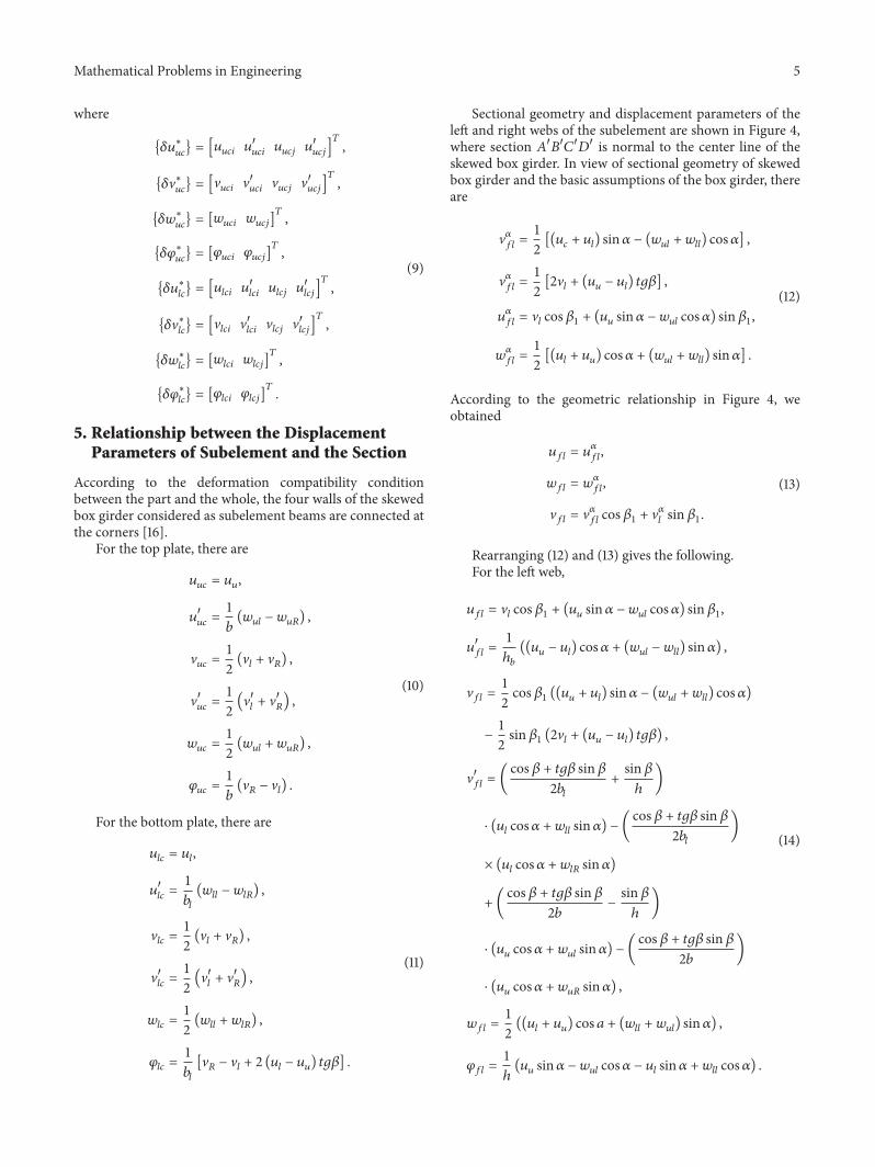

Hindawiwwwhindawicom Volume 2018
MathematicsJournal of
Hindawiwwwhindawicom Volume 2018
Mathematical Problems in Engineering
Applied MathematicsJournal of
Hindawiwwwhindawicom Volume 2018
Probability and StatisticsHindawiwwwhindawicom Volume 2018
Journal of
Hindawiwwwhindawicom Volume 2018
Mathematical PhysicsAdvances in
Complex AnalysisJournal of
Hindawiwwwhindawicom Volume 2018
OptimizationJournal of
Hindawiwwwhindawicom Volume 2018
Hindawiwwwhindawicom Volume 2018
Engineering Mathematics
International Journal of
Hindawiwwwhindawicom Volume 2018
Operations ResearchAdvances in
Journal of
Hindawiwwwhindawicom Volume 2018
Function SpacesAbstract and Applied AnalysisHindawiwwwhindawicom Volume 2018
International Journal of Mathematics and Mathematical Sciences
Hindawiwwwhindawicom Volume 2018
Hindawi Publishing Corporation httpwwwhindawicom Volume 2013Hindawiwwwhindawicom
The Scientific World Journal
Volume 2018
Hindawiwwwhindawicom Volume 2018Volume 2018
Numerical AnalysisNumerical AnalysisNumerical AnalysisNumerical AnalysisNumerical AnalysisNumerical AnalysisNumerical AnalysisNumerical AnalysisNumerical AnalysisNumerical AnalysisNumerical AnalysisNumerical AnalysisAdvances inAdvances in Discrete Dynamics in
Nature and SocietyHindawiwwwhindawicom Volume 2018
Hindawiwwwhindawicom
Dierential EquationsInternational Journal of
Volume 2018
Hindawiwwwhindawicom Volume 2018
Decision SciencesAdvances in
Hindawiwwwhindawicom Volume 2018
AnalysisInternational Journal of
Hindawiwwwhindawicom Volume 2018
Stochastic AnalysisInternational Journal of
Submit your manuscripts atwwwhindawicom