Embed Size (px)
Citation preview
Nguyen et al. EURASIP Journal on Wireless Communications and Networking 2013, 2013:293http://jwcn.eurasipjournals.com/content/2013/1/293
RESEARCH Open Access
A novel link switching scheme using pre-scanningand RSS prediction in visible light communicationnetworksTuan Nguyen1, Mostafa Zaman Chowdhury2 and Yeong Min Jang1*
Abstract
Visible light communication (VLC) is gaining increasing attention and is considered as a promising technology forfuture wireless indoor communications. Because movable users expect a seamless connectivity experience whenswitching among transmitters (i.e., VLC access points) in the VLC system, fast link switching operations must besupported by the networks. This paper presents a novel hard link switching scheme for VLC networks with the useof pre-scanning and received signal strength (RSS) prediction. Our proposed scheme achieves the advantages ofboth conventional hard and soft link switching schemes without changing device hardware or the IEEE 802.15.7medium access control (MAC) protocol. To help compare our proposed scheme with conventional hard and softlink switching schemes, the signal-to-interference-plus-noise ratio (SINR), the outage probability regarding the linkswitching situation, and the queuing models for link switching schemes are taken into account. Simulation andnumerical results validate that our proposed scheme outperforms conventional hard and soft link switching schemes.
Keywords: Link switching; Handover; Pre-scanning; VLC; Visible light communication; RSS prediction; Outage probability
1. IntroductionBecause the requirements for wireless data communicationcontinually increase, the radio frequency spectrum isbecoming congested. Hence, quests for alternative commu-nication technologies have been carried out increasinglyaround the world. In recent years, visible light communi-cation (VLC) has attracted the attention of researchersand has been considered as a promising technology forfuture wireless communications, especially indoor commu-nications. VLC refers to short-range optical wireless com-munication using the visible light spectrum from 380 to780 nm [1]. Compared to radio frequency (RF) tech-nologies, VLC has many advantageous features such ashigh-speed transmission, visibility, high security, harmless-ness to the human body, high tolerance to humidity,ubiquity, and an unlicensed frequency spectrum [2-4]. In2011, VLC technology was standardized by the IEEEorganization in the IEEE 802.15.7 specification [5].
* Correspondence: [email protected] of Electronics Engineering, Kookmin University, Seoul 136-702,South KoreaFull list of author information is available at the end of the article
© 2013 Nguyen et al.; licensee Springer. This isAttribution License (http://creativecommons.orin any medium, provided the original work is p
Link switching, commonly known as handover in otherwireless communication technologies, is an essential issuethat deals with the mobility of end users (the term ‘linkswitching’ is used in the IEEE 802.15.7 standard insteadof ‘handover’). It guarantees seamless connectivity orimproves the quality of service (QoS). In first-generationcellular systems, such as the Advanced Mobile PhoneSystem (AMPS) [6], or second-generation systems suchas the Global System for Mobile Communication (GSM)[7] and Personal Access Communications System (PACS)[8], a hard handover is deployed. In the hard handover,the old radio link is broken before a new radio link isestablished, and a user device only connects to one basestation at any given time. In third-generation systems,which are mainly based on code-division multiple-access(CDMA) technology, the soft handover concept is intro-duced [9]. In a soft handover, a user device can communi-cate with the system using multiple radio links throughdifferent base stations simultaneously. Compared to theconventional hard handover, a soft handover produces asmoother transmission and reduces the so-called ‘ping-pong’ effect [10-12], but it has the disadvantages of imple-mentation complexity and extra resource consumption.
an open access article distributed under the terms of the Creative Commonsg/licenses/by/2.0), which permits unrestricted use, distribution, and reproductionroperly cited.

Nguyen et al. EURASIP Journal on Wireless Communications and Networking 2013, 2013:293 Page 2 of 17http://jwcn.eurasipjournals.com/content/2013/1/293
Handover is a classic research topic. A larger numberof papers have been presented to cope with problems inhandover. Some popular problems include the handoverdelay [13-16], the ping-pong effect, the handover procedurein heterogeneous networks [17-20], and the handoverfailure rate [21-24]. However, as far as we know, thereare not many papers studying link switching in VLCnetworks. In [25], a handover mechanism between Wi-Fiand VLC is proposed to dynamically distribute resourcesto optimize system throughput and to avoid service dis-connections. The work in [26] investigates how handovertechniques can be applied in VLC networks in which userconnectivity switches from one lighting cell to another. In[27], based on minimum QoS requirements of traffic, aflexible resource allocation scheme is proposed to supportlink switching in VLC networks.In this paper, we propose a novel hard link switching
scheme for VLC networks, using a pre-scanning methodand a received signal strength (RSS) prediction scheme,to overcome some drawbacks of conventional hard and softlink switching schemes. Our proposed scheme efficientlyreduces the link switching delay compared to conventionalhard link switching scheme as well as reduces the unneces-sary the link switching ratio and the outage probabilitycompared to conventional hard and soft link switchingschemes. To utilize our proposed scheme, there is no needto change the hardware of user devices as in the case of aconventional soft link switching scheme. Through queuinganalysis, our proposed scheme exhibits lower link switchingcall dropping probability and new call blocking probabilitycompared to a conventional soft link switching scheme.The main contributions of the work in this paper are thefollowing:
1) A novel pre-scanning method, which suits the IEEE802.15.7 medium access control (MAC) operation, isproposed to eliminate the impact of the scanningprocess on the link switching delay.
2) A new serving transmitter selection method,using an RSS prediction method, in the linkswitching decision phase is proposed. Thisapproach can help reduce the unnecessary linkswitching ratio.
3) An in-depth study of the signal-to-interference-plus-noise ratio (SINR) and outage probabilityregarding the link switching situation in a VLCenvironment.
The rest of this paper is organized as follows: Section2 describes the system model of VLC networks includingthe optical channel model, IEEE 802.15.7 MAC, and linkswitching fundamentals. Section 3 presents our proposedfast link switching scheme with a theoretical analysisof SINR, the outage probability, and a queuing model.
Section 4 evaluates the performance of our proposedschemes in terms of several important metrics and incomparison with conventional hard and soft link switch-ing schemes. Finally, Section 5 concludes our work.
2. VLC system modelIn the IEEE 802.15.7 standard, there are three basic devices:a user device, a transmitter, and a single central controllercalled the coordinator. User devices and transmitters usevisible light links to transmit or receive data. Transmittersof a VLC network are managed by a coordinator [5]. TheIEEE 802.15.7 architecture is defined in terms of thenumber of layers and sublayers in order to simplify thestandard. A VLC device is composed of a PHY layer,which contains the light transceiver along with its low-level control mechanism, and a MAC sublayer that pro-vides access to the physical channel for all types of trans-fers. In this section, we represent the optical channelmodel, the IEEE 802.15.7 MAC protocol, and the linkswitching fundamentals.
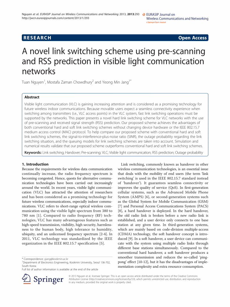
2.1. Optical channel modelThere are two types of links that can be used in a VLCsystem: line-of-sight (LOS) and non-line-of-sight (NLOS),as shown in Figure 1. To achieve a high data rate aswell as to minimize path loss and to maximize thepower efficiency, LOS links should be used. The opticalchannel gain is expressed as
Pr ¼ H 0ð ÞPt ; ð1Þ
where Pt is the transmitted power, Pr is the received power,and H(0) is the channel DC gain.In the case of LOS links, the channel DC gain is
defined as
HLOS 0ð Þ ¼mþ 1ð ÞA2πd2 cosm φð ÞTs ψð Þg ψð Þ cos ψð Þ
0
0 ≤ψ ≤ψcelsewhere
;
(
ð2Þ
where m is the order of the Lambertian emission, A isthe photodetector area, d is the distance between thetransmitter and user device, φ is the angle of irradiance,ψ is the angle of incidence, Ts(ψ) is the signal transmis-sion coefficient of an optical filter, g(ψ) is the gain of anoptical concentrator, and ψc is the receiver field of view(FOV).The order of the Lambertian emission, m, is found
from the following equation:
m ¼ −ln2
ln cosϕ1=2
� � ; ð3Þ
where ϕ1/2 is the transmitter semi-angle at half power.
1/2NLOS link
LOS link
Transmitter#1
d
User device
Transmitter#2
Data server
IP Network
Coordinator
d2
d1
1
2
Figure 1 Transmission model with LOS and NLOS links.
Nguyen et al. EURASIP Journal on Wireless Communications and Networking 2013, 2013:293 Page 3 of 17http://jwcn.eurasipjournals.com/content/2013/1/293
The gain of an optical concentrator, g(ψ), is foundfrom the following equation:
g ψð Þ ¼α2
sin2 ψcð Þ0
0 ≤ψ ≤ψc
elsewhere;
8<: ð4Þ
where α is the refractive index of the optical concentrator.In the case of NLOS links, the channel DC gain on the
first reflection is
HNLOS 0ð Þ ¼mþ 1ð ÞA2πd2
1d22
ΛAwall cosm φð Þcos α1ð Þcos α2ð ÞTs ψð Þg ψð Þ cos ψð Þ
00 ≤ψ ≤ψcelsewhere
;
8>>>><>>>>:
ð5Þ
where Λ is the reflectance factor, Awall is the reflectivearea of a small region, α1 is the angle of irradiance to areflective point, α2 is the angle of irradiance to thereceiver, d1 is the distance between the transmitterand the reflective point, and d2 is the distance betweenthe reflective point and the user device.In this paper, in order to simplify the theoretical analysis
as well as the simulation, we assume that the channels ofthe VLC system are Rician channels in which LOS linksare the strong dominant components.
2.2. IEEE 802.15.7 MAC protocolThe IEEE 802.15.7 MAC protocol [5], as well as theIEEE 802.15.4 MAC protocol [28], supports both beacon-enabled mode and non-beacon-enabled mode. In thenon-beacon-enabled mode, it is a simple unslotted random
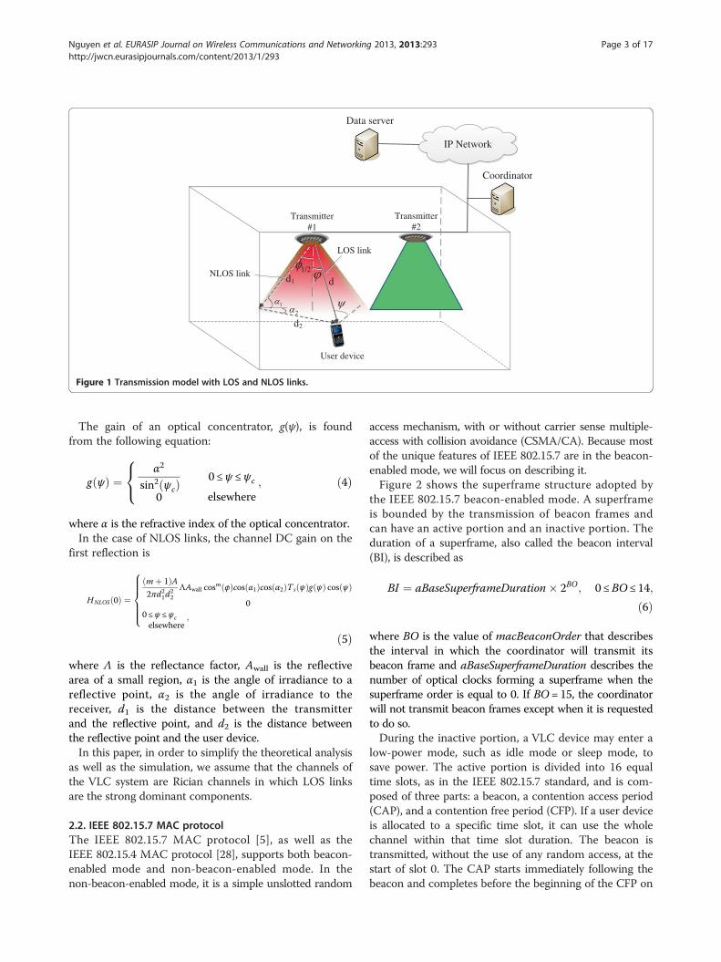
access mechanism, with or without carrier sense multiple-access with collision avoidance (CSMA/CA). Because mostof the unique features of IEEE 802.15.7 are in the beacon-enabled mode, we will focus on describing it.Figure 2 shows the superframe structure adopted by
the IEEE 802.15.7 beacon-enabled mode. A superframeis bounded by the transmission of beacon frames andcan have an active portion and an inactive portion. Theduration of a superframe, also called the beacon interval(BI), is described as
BI ¼ aBaseSuperframeDuration� 2BO; 0 ≤BO ≤ 14;
ð6Þ
where BO is the value of macBeaconOrder that describesthe interval in which the coordinator will transmit itsbeacon frame and aBaseSuperframeDuration describes thenumber of optical clocks forming a superframe when thesuperframe order is equal to 0. If BO = 15, the coordinatorwill not transmit beacon frames except when it is requestedto do so.During the inactive portion, a VLC device may enter a
low-power mode, such as idle mode or sleep mode, tosave power. The active portion is divided into 16 equaltime slots, as in the IEEE 802.15.7 standard, and is com-posed of three parts: a beacon, a contention access period(CAP), and a contention free period (CFP). If a user deviceis allocated to a specific time slot, it can use the wholechannel within that time slot duration. The beacon istransmitted, without the use of any random access, at thestart of slot 0. The CAP starts immediately following thebeacon and completes before the beginning of the CFP on
0 1 2 3 4 5 6 7 8 9 10 11 12 13 14 15
Inactive
CAP CFP
GTS GTS GTS
Beacon Beacon
SD = aBaseSuperframeDuration*2SO optical clocks
BI = aBaseSuperframeDuration*2BO optical clocks
Figure 2 IEEE 802.15.7 superframe structure.
Nguyen et al. EURASIP Journal on Wireless Communications and Networking 2013, 2013:293 Page 4 of 17http://jwcn.eurasipjournals.com/content/2013/1/293
a superframe slot boundary. The duration of the activeportion, denoted as SD, is described as
SD ¼ aBaseSuperframeDuration� 2SO; 0 ≤ SO ≤ 14;
ð7Þ
where SO is the value of macSuperframeOrder thatdescribes the length of the active portion of a superframe.If SO = 15, the superframe will not remain after the beacon.In CAP, devices use a slotted CSMA/CA mechanism
to access the channel. The CFP is dedicated to supporttime-critical data transfers generated by the applicationsthat require specific data bandwidth or low latency. InCFP, data are transmitted in guaranteed time slots (GTS).A GTS can be allocated to an integer number of timeslots, and GTSs are allocated on a first-come-first-served(FCFS) basis. Each GTS is reallocated when it is no longerrequired, or when it has not been used for a specifiedduration.
2.3. Link switching fundamentalsTo support the mobility of user devices, the IEEE 802.15.7standard presents the usage of cell design and PHY switch[5]. These procedures may be efficiently applicable withina VLC network where user devices do not need to changethe network information, such as network ID, and theMAC operation during their movements in order to main-tain the data transmission. Besides, in using these proce-dures, outage may happen because there is no guaranteeon the quality of signals (for example, these procedures donot cope with the situation that the RSS of a user devicemay drop seriously when the user device moves to/moveout of the boundary area of a cell). Generally, to supportthe mobility of user devices within a VLC network as wellas among VLC networks, link switching (i.e., handover) isa comprehensive solution.
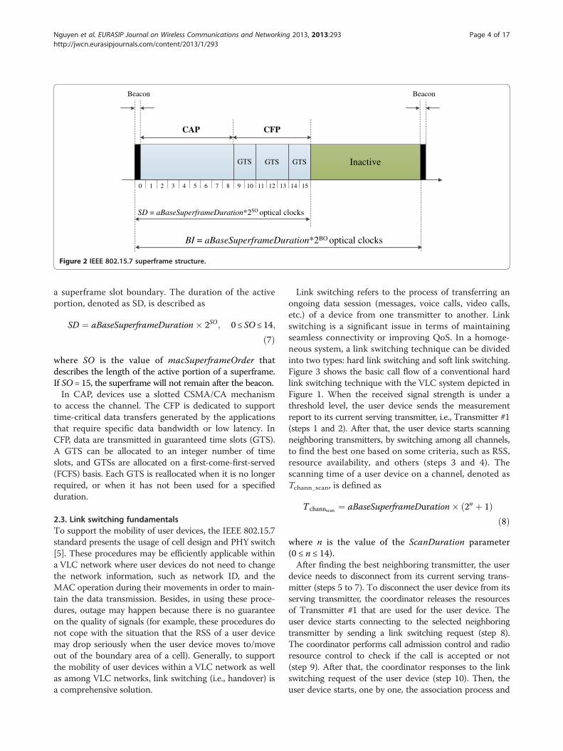
Link switching refers to the process of transferring anongoing data session (messages, voice calls, video calls,etc.) of a device from one transmitter to another. Linkswitching is a significant issue in terms of maintainingseamless connectivity or improving QoS. In a homoge-neous system, a link switching technique can be dividedinto two types: hard link switching and soft link switching.Figure 3 shows the basic call flow of a conventional hardlink switching technique with the VLC system depicted inFigure 1. When the received signal strength is under athreshold level, the user device sends the measurementreport to its current serving transmitter, i.e., Transmitter #1(steps 1 and 2). After that, the user device starts scanningneighboring transmitters, by switching among all channels,to find the best one based on some criteria, such as RSS,resource availability, and others (steps 3 and 4). Thescanning time of a user device on a channel, denoted asTchann_scan, is defined as
T channscan ¼ aBaseSuperframeDuration� 2n þ 1ð Þð8Þ
where n is the value of the ScanDuration parameter(0 ≤ n ≤ 14).After finding the best neighboring transmitter, the user
device needs to disconnect from its current serving trans-mitter (steps 5 to 7). To disconnect the user device from itsserving transmitter, the coordinator releases the resourcesof Transmitter #1 that are used for the user device. Theuser device starts connecting to the selected neighboringtransmitter by sending a link switching request (step 8).The coordinator performs call admission control and radioresource control to check if the call is accepted or not(step 9). After that, the coordinator responses to the linkswitching request of the user device (step 10). Then, theuser device starts, one by one, the association process and
User deviceTransmitter
#1Coordinator
1. Received signalis going down
3. Scan neighbor transmittersto find out the best one
Transmitter#2
6a. Accept device’s request6b. Release resource used for the device
4. Decide the next servingtransmitter
2. Measurement report
5. Link disconnectionrequest
request5. Link disconnection
7. Link disconnectionresponse7. Link disconnection
response
8. Link switching request
8. Link switching request
9. Call admission control andradio resource control for
Transmitter #2
10. Link switching response
10. Link switching response
11. Association request
11. Association request
12. Association response
12. Association response
13. Synchronization request
13. Synchronization request
14. Synchronization response
14. Synchronization response
DataData
Figure 3 Conventional hard link switching call flow.
Nguyen et al. EURASIP Journal on Wireless Communications and Networking 2013, 2013:293 Page 5 of 17http://jwcn.eurasipjournals.com/content/2013/1/293
synchronization process with the selected neighboringtransmitter, i.e., Transmitter #2 (steps 11 to 14). The userdevice and the selected neighboring transmitter exchangeinformation such as the network ID, beacon interval, theaddresses of the devices, and the channel identification.Finally, the data are sent to the user device throughTransmitter #2.During a hard link switching procedure, user devices
cannot receive the signal from the serving transmitter,
which leads to a data interruption problem and then QoSdegradation. Thus, the process duration of a hard linkswitching scheme (i.e., link switching delay), which mainlyoriginates from the scanning period, is an important prob-lem in terms of guaranteeing a seamless data transmission.This problem can be solved effectively in soft link switch-ing. In soft link switching, a user device can simultaneouslycommunicate with two or more transmitters, includingits current serving transmitter. The link between the

Nguyen et al. EURASIP Journal on Wireless Communications and Networking 2013, 2013:293 Page 6 of 17http://jwcn.eurasipjournals.com/content/2013/1/293
user device and its current serving transmitter is discon-nected only after it has successfully connected to the targettransmitter.The main advantage of soft link switching over hard
link switching is a better guarantee in data transmission,which originates from the significantly smaller linkswitching delay. However, to utilize soft link switching,the hardware of user devices must be more complexand expensive compared to that of hard link switchingto be able to receive signals from many transmitterssimultaneously. Another problem of the soft link switchingtechnique is the use of several channels to only support asingle user device, which results in a waste of resources,an increase in the volume of data traffic, and an increasein downlink interference.A link switching may be interrupted in case the user
device or the transmitter does not receive the linkswitching-related signals due to certain factors (such asinterference) or the available resources of the selectedneighboring transmitter are not enough to be allocated tothe user device. To solve these problems, the IEEE802.15.7 standard presents the fast link recovery andmultiple-channel resource assignment procedures [5].The details of these procedures are beyond the scopeof this paper.
3. Proposed hard link switching schemeIn this section, we represent our proposed link switchingscheme for a VLC system exploiting the operation of theIEEE 802.15.7 MAC protocol. By using our scheme, wecan eliminate the scanning period, which has the largestimpact on the link switching delay, in a link switchingprocedure. Additionally, our proposed scheme does notrequire a change in IEEE 802.15.7 MAC operation andthe hardware of user devices as in the case of a soft linkswitching technique. The theoretical analysis of the pro-posed scheme is also presented in this Section.
3.1. Proposed link switching schemeAs mentioned before, in the IEEE 802.15.7 MAC protocol,during the inactive portion, VLC devices may enter alow-power mode, such as idle or sleep mode. Our pro-posed scheme utilizes this period for user devices toscan channels, associate, and synchronize with a targettransmitter, respectively.The main steps of our proposed scheme are depicted
in Figure 4. During its operation in a VLC system, afterhaving received a signal from its current serving transmit-ter, a user device measures the received signal strength,denoted as Pr,curr. The value of Pr,curr is compared to threethresholds, denoted as Scan_thr, Assoc_thr, and LS_thr(Scan_thr > Assoc_thr > LS_thr), to determine the nextprocess precisely. These three thresholds divide theproposed link switching procedure into three periods
called pre-scanning, pre-association, and the final linkswitching decision.
3.1.1. Pre-scanning periodA user device initiates the pre-scanning process if thefollowing criterion is met:
Assoc thr ≤Pr;curr < Scan thr ð9Þ
In the pre-scanning period, firstly, the user device scansall the channels, using either active scanning or passivescanning, to find the neighboring transmitters. To achievethis task and in order not to interrupt data reception fromthe current serving transmitter of the user device, thescanning time of all channels should be shorter thanthe duration of the inactive portion of the superframe.To fulfill this requirement, based on Equations (6) to(8), the value of the ScanDuration parameter, n, needsto satisfy the following equation:
2BO− 2SO > k 2n þ 1ð Þ; ð10Þ
where k is the number of channels in a VLC system. Inthe IEEE 802.15.7 standard, the value of k is 7.After the scanning process, the user device saves all
the values of the RSSs measured from the signals ofneighboring transmitters. Finally, the user device returns toreceive data following the IEEE 802.15.7 MAC superframeoperation.The pre-scanning procedure may be initiated if the
current RSS of the user device satisfies Equation (9).This work has two purposes:– All the saved values of RSSs from the signals of
neighboring transmitters will be used in the pre-associationprocess for determining the best neighboring transmitter.The detailed steps are explained in the next section.– During the scanning process, because of several factors,
such as interference, noise, channel access failure, transmis-sion speed, and short scanning time on channels, a userdevice may not receive beacon signals from a (or some)neighboring transmitter(s). Thus, multiple pre-scanningshelp a user device to eliminate this problem; since then,the scanning result is improved.In reality, the movement of user devices is random. This
problem results in the random variation of the RSS. Insome cases, after a duration in which the value of Pr,curr isbelow the Scan_thr threshold, Pr,curr then becomes higherthan Scan_thr, and is maintained for a sufficiently longduration (for example, when a user device first arrives inthe boundary area of its current serving transmitter andthen returns towards the current serving transmitter, itsPr,curr value may change from a weak value to a strongvalue). In these cases, the saved RSS values from thesignals of neighboring transmitters are not valuable now.
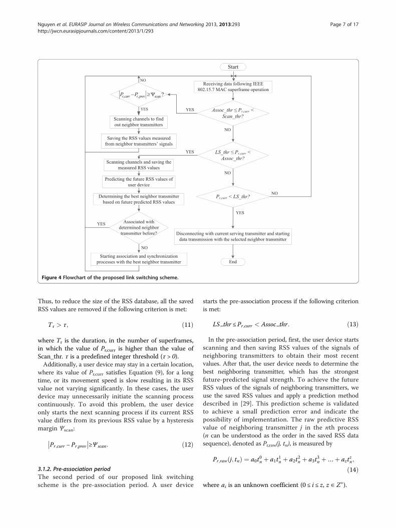
Figure 4 Flowchart of the proposed link switching scheme.
Nguyen et al. EURASIP Journal on Wireless Communications and Networking 2013, 2013:293 Page 7 of 17http://jwcn.eurasipjournals.com/content/2013/1/293
Thus, to reduce the size of the RSS database, all the savedRSS values are removed if the following criterion is met:
T r > τ; ð11Þ
where Tr is the duration, in the number of superframes,in which the value of Pr,curr is higher than the value ofScan_thr. τ is a predefined integer threshold (τ > 0).Additionally, a user device may stay in a certain location,
where its value of Pr,curr satisfies Equation (9), for a longtime, or its movement speed is slow resulting in its RSSvalue not varying significantly. In these cases, the userdevice may unnecessarily initiate the scanning processcontinuously. To avoid this problem, the user deviceonly starts the next scanning process if its current RSSvalue differs from its previous RSS value by a hysteresismargin Ψscan:
Pr;curr − Pr;prev
�� ��≥Ψ scan: ð12Þ
3.1.2. Pre-association periodThe second period of our proposed link switchingscheme is the pre-association period. A user device
starts the pre-association process if the following criterionis met:
LS thr ≤Pr;curr < Assoc thr: ð13Þ
In the pre-association period, first, the user device startsscanning and then saving RSS values of the signals ofneighboring transmitters to obtain their most recentvalues. After that, the user device needs to determine thebest neighboring transmitter, which has the strongestfuture-predicted signal strength. To achieve the futureRSS values of the signals of neighboring transmitters, weuse the saved RSS values and apply a prediction methoddescribed in [29]. This prediction scheme is validatedto achieve a small prediction error and indicate thepossibility of implementation. The raw predictive RSSvalue of neighboring transmitter j in the nth process(n can be understood as the order in the saved RSS datasequence), denoted as Pr,raw(j, tn), is measured by
Pr;raw j; tnð Þ ¼ a0t0n þ a1t
1n þ a2t
2n þ a3t
3n þ…þ azt
zn;
ð14Þ
where ai is an unknown coefficient (0 ≤ i ≤ z, z ∈ Z+).
Nguyen et al. EURASIP Journal on Wireless Communications and Networking 2013, 2013:293 Page 8 of 17http://jwcn.eurasipjournals.com/content/2013/1/293
The values of the coefficients are obtained from thefollowing polynomials:
a0Xni¼1
t0i
!þ a1
Xni¼1
t1i
!þ a2
Xni¼1
t2i
!þ a3
Xni¼1
t3i
!þ…þ az
Xni¼1
tzi
!¼Xni¼1
t0i Pr j; tnð Þ
a0Xni¼1
t1i
!þ a1
Xni¼1
t2i
!þ a2
Xni¼1
t3i
!þ a3
Xni¼1
t4i
!þ…þ az
Xni¼1
tzþ1i
!¼Xni¼1
t1i Pr j; tnð Þ⋮ ⋮ ⋮ ⋮ ⋮ ⋮
a0Xni¼1
tzi
!þ a1
Xni¼1
tzþ1i
!þ a2
Xni¼1
tzþ2i
!þ a3
Xni¼1
tzþ3i
!þ…þ az
Xni¼1
t2zi
!¼Xni¼1
tzi Pr j; tnð Þ
;
8>>>>>>>>>>><>>>>>>>>>>>:
ð15Þ
where Pr(j, tn) is the saved RSS value in the nth process.If we consider coefficients as variables, by applying the
Gauss elimination method [30] to Equation (15), wecalculate all the coefficients as
ai ¼ 1Ai;i
bi−Xzj¼iþ1
Ai;iaj
!; ð16Þ
where Ai,i and bi are elements of the augmented coeffi-cient matrix that is generated after several steps of Gausselimination.The final predictive RSS value in the (n + 1)th process,
which is used for determining the best neighboringtransmitter, is denoted as Pr,pred(j, tn+1) and is calculated as
Pr;pred j; tnþ1ð Þ ¼ Pr;raw j; tnþ1ð Þ−Xnj¼1
Pr j; tj� � ð17Þ
After obtaining the predictive RSS values (i.e., Pr,pred(j, tn+1)) of all neighboring transmitters, the user devicestarts association and synchronization with the bestneighboring transmitter that satisfies the three followingcriteria:
a) The user device is moving closer to this neighboringtransmitter, which is expressed by the followingequation:
Pr;pred j; tnþ1ð Þ−Pr j; tnð Þ > 0 ð18Þ
b) The value of Pr,pred(j, tn+1) of this neighboringtransmitter is higher than the value of LS_thr.
c) Among neighboring transmitters that satisfy criteria(a) and (b), the best neighboring transmitter is theone whose predictive RSS value is highest.
Finally, the user device returns to receive data followingthe IEEE 802.15.7 MAC superframe operation.The pre-association procedure may happen several times
because the value of Pr,curr of a user device may be in the
range of [LS_thr;Assoc_thr) in some superframe periods.Thus, to reduce the necessity of performing association andsynchronization processes with the same neighboring trans-mitter, before starting these two processes, if a user deviceis already associated with the selected neighboring trans-mitter, it will skip these processes and return to receive datafrom its current transmitter in the next superframe.The difference between our proposed scheme and
a soft link switching scheme is that, after the pre-association procedure, a user device does not transmitand receive data with the selected neighboring transmit-ter. It only keeps pieces of information related to thatneighboring transmitter, such as the address, beaconinterval, channel identification, and network identifica-tion, which are used to connect to that transmitter inthe final phase of our proposed link switching scheme.This work helps avoid the waste of resources caused byusing several channels to support just a single userdevice.
3.1.3. Final link switching decisionThe final period of our proposed scheme is started whenthe value of Pr,curr of a user device is smaller than theLS_thr threshold. At this time, first, the user devicedisassociates with its current serving transmitter anddeletes all the information related to it. Because theuser device has already used the resources of this trans-mitter, it cannot disassociate itself as we explained above.In this case, the user device needs to send a disassociationmessage to its current serving transmitter so that thistransmitter can release resources allocated for the userdevice to avoid the waste of resources.Finally, by using information gained in the pre-associ-
ation period, the user device switches to the channel ofthe neighboring transmitter, which was selected in thepre-association period, and follows the superframe oper-ation of this transmitter. Now, the selected neighboringtransmitter becomes the new serving transmitter of theuser device.
Nguyen et al. EURASIP Journal on Wireless Communications and Networking 2013, 2013:293 Page 9 of 17http://jwcn.eurasipjournals.com/content/2013/1/293
3.2. Theoretical analysisThe outage probability is an important metric in wirelesscommunication systems. To maintain the QoS, the RSS,or the SINR needs to be maintained above a certainthreshold. In this paper, we focus on analyzing the out-age probability with respect to three link switchingschemes, which are conventional hard link switching,conventional soft link switching, and our proposed linkswitching.
3.2.1. SINR calculationWe assume that all transmitters have the same transmittedpower. Thus, the inter-cell interference to the connectionbetween a user device and transmitter i at location x,denoted as ICIx,i, is given by
ICIx;i ¼XNt
j¼1
βPtH x; jð Þ; ð19Þ
where Nt is the total number of neighboring transmitters,H(x, j) is the channel DC gain at location x with respect totransmitter j, and β is the detector responsivity.Let SNRx,i denote the signal-to-noise ratio of the signal
received from transmitter i when the user device is atlocation x. The value of SNRx,i is calculated as [31].
SNRx;i ¼ βPr x; ið Þð Þ2σ2total
; ð20Þ
where Pr(x, i) is the received power at location x withrespect to transmitter i, and σ2total is the total variance ofthe Gaussian noise, which is the sum of contributionsfrom the shot noise and thermal noise:
σ2total ¼ σ2shot þ σ2thermal ð21Þ
Consequently, we have
SNRx;i ¼ βPr x; ið Þð Þ2σ2shot þ σ2thermal
¼ βPtH x; ið Þð Þ2σ2shot þ σ2thermal
ð22Þ
The value of SINRx,i is expressed as
SINRx;i ¼ βPtH x; ið Þð Þ2ICI2x;i þ σ2
shot þ σ2thermal
ð23Þ
In a VLC network, at a certain time, there is only oneuser device using the channel of a transmitter. Thus, intra-cell interference does not occur, and we do not take intoaccount intra-cell interference in this paper.
3.2.2. Outage probabilityThe outage probability at a location is defined as theprobability that the SINR value at that location is lessthan a specified threshold Out_thr. It is calculated as
Rout;x ið Þ ¼ R SINRx;i < Out thr� �
¼Z∞−∞
R�SINRx;i < Out thrjGσ ¼ Go�:R Gσ ¼ Go½ �dGo
¼Z∞−∞
R�SINRx;i < Out thrjGσ ¼ Go�: 1ffiffiffiffiffiffi
2πp
σe−
G2o2σ2dGo
ð24Þwhere Rout,x(i) is the outage probability at location x withrespect to transmitter i.Substituting Equation (23) into Equation (24), we have
Rout;x ið Þ ¼Z∞−∞
R
"βPtH x; ið Þð Þ2
ICI2x;i þ σ2shot þ σ2
thermal
< Out thrjGσ ¼ Go
#
� 1ffiffiffiffiffiffi2π
pσe−
G2o2σ2dGo
¼Z∞−∞
R
"H x; ið Þ
<
ffiffiffiffiffiffiffiffiffiffiffiffiffiffiffiffiffiffiffiffiffiffiffiffiffiffiffiffiffiffiffiffiffiffiffiffiffiffiffiffiffiffiffiffiffiffiffiffiffiffiffiffiffiffiffiffiffiffiffiffiffiffiffiffiffiffiffiOut thr ICI2x;i þ σ2
shot þ σ2thermal
� �rβPt
jGσ ¼ Go
#
� 1ffiffiffiffiffiffi2π
pσe−
G2o2σ2dGo
ð25ÞThe path loss model of the VLC system is given as [32]
N x; ið Þ ¼ 10 logPt
E dref x; ið Þ� �A0
!−10 log
AA0
�
þ 10p logd x; ið Þdref x; ið Þ �
þ Gσ ;
ð26Þwhere N(x, i) is the path loss at location x with respectto transmitter i, d(x,i) is the distance between the userdevice and transmitter i at location x, dref(x, i) is thereference distance, E(dref (x,i)) is the irradiance at thereference distance dref(x, i), A0 is the reference photo-detector area, Gσ is a zero-mean Gaussian distributedrandom variable with standard deviation σ, and p is thepath loss exponent.Because N(x, i) is a random variable with a normal
distribution, so is the received power Pr(x, j). FromEquation (1), the channel DC gain can be stated as a
Nguyen et al. EURASIP Journal on Wireless Communications and Networking 2013, 2013:293 Page 10 of 17http://jwcn.eurasipjournals.com/content/2013/1/293
random variable with a normal distribution (in dB) aboutthe distance-dependent mean. Thus, the value of Rout,x(i)is calculated using the Q-function:
Q αð Þ ¼ 1ffiffiffiffiffiffi2π
pZ∞α
e−x22 dx ð27Þ
Therefore, we write
Rout;x ið Þ ¼Z∞−∞
Q�H x; ið Þ−
ffiffiffiffiffiffiffiffiffiffiffiffiffiffiffiffiffiffiffiffiffiffiffiffiffiffiffiffiffiffiffiffiffiffiffiffiffiffiffiffiffiffiffiffiffiOut thr ICI2x;iþσ2shotþσ2thermalð Þp
βPt
σ
0B@
1CA:
1ffiffiffiffiffiffi2π
pσe−
G2o2σ2dGo;
ð28Þwhere �H x; ið Þ is the average value of the channel DCgain when the user device is at location x.The probability that the user device, whose current
serving transmitter is transmitter i, does not need toutilize link switching at location x is defined as theprobability that its received signal strength is not lessthan the LS_thr threshold. This probability, denoted asRnls,x(i), is calculated as
Rnls;x ið Þ ¼ R Pr x; ið Þ ≥ LS thrð Þ ¼ R H x; ið Þ ≥ LS thrPt
�
¼Z∞−∞
QLS thr
Pt− �H x; ið Þσ
!:
1ffiffiffiffiffiffi2π
pσe−
G2o2σ2dGo
ð29ÞIn the case that the user device needs to utilize link
switching at location x and time tn+1, the probability, de-noted as Rx(i, j), that it chooses the neighboring trans-mitter j as the next serving transmitter is expressed as
Rx i; jð Þ ¼ R�Pr;pred j; tnþ1ð Þ≥LS thr� �
& Pr;pred j; tnþ1ð Þ > Pr;pred k; tnþ1ð Þ� �& Pr;pred j; tnþ1ð Þ‐Pr j; tnð Þ > 0� ��
ð30Þsubject to j ≠ k, ∀ j, k ∈ Nt.Equation (30) is derived as
Rx i; jð Þ ¼ R Pr;pred j; tnþ1ð Þ≥LS thr� ��
Yk≠j;∀k;j∈Nt
R Pr;pred j; tnþ1ð Þ > Pr;pred k; tnþ1ð Þ� �
�R Pr;pred j; tnþ1ð Þ‐Pr j; tnð Þ > 0� �
ð31ÞTo simplify the analysis, we assume that
R Pr;pred j; tnþ1ð Þ‐Pr j; tnð Þ > 0� � ¼ 1 ð32Þ
and
Pr;pred j; tnþ1ð Þ ¼ γPr x; jð Þ; ð33Þ
where γ is the ratio that represents the mean relative ac-curacy of the prediction scheme (γ > 0). The value of γ iscalculated as
γ ¼ 1−1M
X Pr;pred−Pr
�� ��Pr
; ð34Þ
where M is the total number of prediction samples.Substituting Equations (32) and (33) into Equation (31),
we have
Rx i; jð Þ ¼Z∞−∞
R γPr x; jð Þ≥LS thrjGσ ¼ Go½ �
�Y
k≠j;∀k;j∈Nt
R Pr x; jð Þ > Pr x; kð ÞjGσ ¼ Go½ �:R Gσ ¼ Go½ �dGo
¼Z∞−∞
Q
LS thrγPt
− �H x; jð Þσ
!:Y
k≠j;∀k;j∈N
QH x; kð Þ− �H x; jð Þ
σ
�
� 1ffiffiffiffiffiffi2π
pσe−
G2o2σ2dGo
ð35Þ
Equation (28) represents the outage probability of theuser device, whose location and current serving transmitterare x and i, respectively, regardless of the link switchingsituation. If we consider the link switching situation, theoutage probability of a conventional hard link switchingscheme, denoted as Rh
out;x ið Þ, is expressed as
Rhout;x ið Þ ¼ Rnlsw;x ið ÞRout;x ið Þ þ 1−Rnls;x ið Þ� �
� 1−RhD
� �Rx i; jð ÞRout;x jð Þ þ Rh
DRx i; jð ÞRout;x ið Þ� �;
ð36Þ
where RhD is the call dropping probability of a conventional
hard link switching scheme.To calculate the outage probability of a conventional
soft link switching scheme, we need to take into accounttwo connection links of the user device. This outageprobability is calculated as
Rsout;x ið Þ ¼ Rnlsw;x ið ÞRout;x ið Þ þ 1−Rnls;x ið Þ� �
�� 1−RsD
� �Rx i; jð ÞRout;x ið ÞRout;x jð Þ
þRsDRx i; jð ÞRout;x ið Þ�
ð37Þ
where Rsout;x ið Þ and Rs
D are the outage probability and thecall dropping probability of a conventional soft linkswitching scheme, respectively.Similar to the case of conventional soft link switching
scheme, the outage probability of our proposed schemerepresents the connections of the user device with its
Nguyen et al. EURASIP Journal on Wireless Communications and Networking 2013, 2013:293 Page 11 of 17http://jwcn.eurasipjournals.com/content/2013/1/293
current serving transmitter and the selected neighboringtransmitter:
Rpropout;x ið Þ ¼ Rnlsw;x ið ÞRout;x ið Þ þ 1−Rnls;x ið Þ� �
�� 1−RpropDð ÞRx i; jð ÞRout;x ið ÞRout;x jð Þ
þRpropD Rx i; jð ÞRout;x ið Þ�;
ð38Þ
where Rpropout;x ið Þ and Rprop
D are the outage probability andthe call dropping probability of our proposed scheme,respectively.
3.2.3. Queuing analysisTo calculate the link switching call dropping probability,we use an M/M/K/K queuing model. We assume that thearrival and departure are Poisson processes. The states ofthis M/M/K/K queue represent the number of calls in thesystem. Let S and Sreq be the total number of time slots inthe system and the average number of required time slotsfor a call. We respectively denote λn and λh as the arrivalrates of new calls and link switching calls. The relationbetween λn and λh is expressed by
λh ¼ Rh 1−RBð Þ1−Rh 1−RDð Þ½ � λn; ð39Þ
where Rh, RB, and RD are the link switching probabilityof a call, the new call blocking probability, and the linkswitching call dropping probability, respectively.The link switching probability of a call depends on
two factors: the average channel dwell time (1/η) andthe average call duration (1/μ). Both the call durationand the cell dwell time are assumed to be exponential.Rh is calculated as
Rh ¼ η
ηþ μð40Þ
Additionally, the time slot release rate is calculated as
μr ¼ ηþ μ ð41ÞThe average channel dwell time depends on the time a
user device stays in the non-overlay area of transmitter i(1/χ) and the time the user device stays in the overlayarea between transmitter i and neighboring transmitteri + 1 (1/p). In the cases of the hard link switchingscheme and our proposed scheme, this relation isexpressed as
1ηh
¼ 1ηprop
¼ 1χþ 1ρ¼ χ þ ρ
χρð42Þ
In terms of the queuing model, there is no differencebetween our proposed scheme and the conventionalhard link switching scheme. Figure 5 shows the Markovchain of the conventional hard link switching scheme
and our proposed scheme. The maximum number of statesin the system, denoted as N, is calculated as
N ¼ SSreq
ð43Þ
By using the Erlang-B formula, the new call blockingprobability and the link switching call dropping probabilityare calculated as
RhD ¼ Rprop
D ¼ RhB ¼ Rprop
B ¼ λn þ λhð ÞNN ! μrð ÞN
XNi¼0
λn þ λhð Þii! μrð Þi
" #−1
ð44ÞTo support a soft link switching call, the system needs to
use multiple channels simultaneously. Thus, the queuingmodel of the conventional soft link switching scheme isdifferent from those of our proposed scheme and theconventional hard link switching scheme. Figure 6 showsthe Markov chain of the conventional soft link switchingscheme. We assume that a user device can connect withup to two transmitters during the soft link switchingprocedure. The average channel dwell time in this caseis calculated as
1ηs
¼ 1χþ 1ρþ 1ρ¼ 2χ þ ρ
χρð45Þ
When the system is in state k (0 ≤ k ≤N), the systemresources (i.e., time slots) are released with rate k(μ + ηs).When the system is in state N + j (0 ≤ j <∞), all resourcesare used, and j link switching calls are looking for sec-ond links. If a new call arrives at state N+ j, it is blockedimmediately. Among all allocated calls, a completed callreleases its resources with rate N(μ + ηs ). For those j softlink switching calls, the calls leave the system if theuser device leaves the overlay area (with rate ρ) or itis completed (with rate μ). Thus, the probability thatthe system is in state i (0 ≤ i <∞) is expressed as
R ið Þ ¼
λn þ λhð Þii! μþ ηs� �i R 0ð Þ
λn þ λhð ÞN λhð Þi−N
N ! μþ ηs� �NYi−N
j¼1
N μþ ηs� �þ j μþ ρð Þ� �R 0ð Þ
0 < i≤N
N þ 1 ≤ i < ∞;
8>>>>>>><>>>>>>>:
ð46Þwhere R(0) is calculated from the normalizing conditionX∞n¼0
Rn ¼ 1:
R 0ð Þ ¼XNi¼0
λn þ λhð Þii! μþ ηs� �i þ X∞
i¼Nþ1
λn þ λhð ÞN λhð Þi−N
N ! μþ ηs� �NYi−N
j¼1
N μþ ηs� �þ j μþ ρð Þ� �
266664
377775
−1
ð47Þ

Figure 5 Markov chain of the conventional hard and proposed link switching schemes.
Nguyen et al. EURASIP Journal on Wireless Communications and Networking 2013, 2013:293 Page 12 of 17http://jwcn.eurasipjournals.com/content/2013/1/293
A new call is blocked if the system is in state i (N ≤ i <∞).Thus, the new call blocking probability of the soft linkswitching scheme is expressed as
RsB ¼
X∞i¼N
R ið Þ
¼X∞i¼N
λn þ λhð ÞN λhð Þi−N
N−1ð Þ! μþ ηs� �N−1Yi−N
j¼0
N μþ ηs� �þ j μþ ρð Þ� �R 0ð Þ
ð48Þ
A soft link switching call l is dropped in case that thesystem is in state i (N ≤ i <∞), all existing link switchingcalls and at least one allocated call do not leave the systembefore call l leaves the overlay area. The soft link switchingcall dropping probability is calculated as
RsD ¼
X∞j¼0
(1−
μþ ρ
N μþ ηs� �þ μþ ρ
!
�Yjþ1
n¼1
1−μþ ρ
N μþ ηs� �þ μþ ρ
!12
�n" #)
R N þ jð Þ
ð49Þ
4. Performance evaluationIn this section, we evaluate the performance of ourproposed link switching scheme by comparing it to con-ventional hard and soft link switching schemes. Severalperformance metrics are used for the comparison, includingthe link switching delay, unnecessary link switching ratio,new call blocking probability, link switching call dropping
Figure 6 Markov chain of the conventional soft link switching scheme
probability, and outage probability. We obtain both thesimulated and numerical results to evaluate three linkswitching schemes. Table 1 shows the list of assumedparameters for the performance evaluation.Regarding the simulation, we focused on building and
analyzing the VLC MAC operation with a superframestructure, the conventional and proposed link switch-ing procedures, and the channel path loss model that isshown in Equation (26). The transmitters we arranged in aroom whose dimensions were fixed during the simulation.The distance between two adjacent transmitters wasinitially set to 3 m and was decreased when the number oftransmitters used in the simulation was increased. Inaddition, in our simulation, the velocities of the userdevices were equal and kept constant. To obtain objectiveresults, the trajectories of the user devices were randomlyarranged into various configurations, such as zigzag, arcline, straight line, etc.Figure 7 shows a comparison of the average link switching
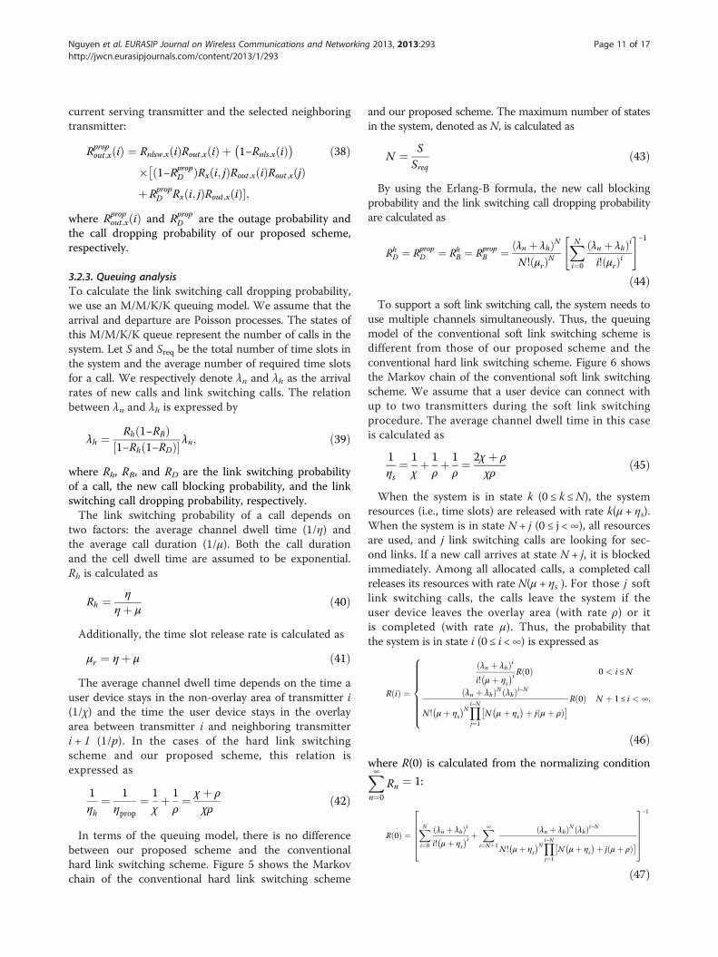
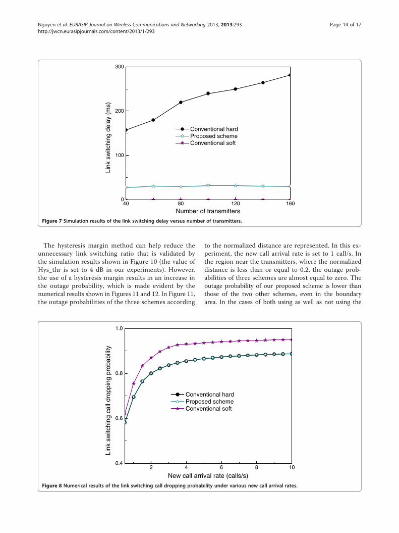
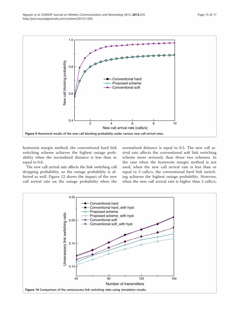
delay among three schemes used in the simulation. In thisexperiment, the conventional hard link switching schemehas the worst performance. During the conventional softlink switching procedure, the connections between userdevices and their serving transmitters are maintained, sothe conventional soft link switching delay is zero regardlessof the number of transmitters. By eliminating the scanningperiod, which is the main cause of the link switching delay,our proposed scheme effectively reduces the data transmis-sion interruption. The link switching delay of our proposedscheme only suffers from a disassociation process betweenuser devices and their current serving transmitters.Figures 8 and 9 show the numerical results of the link
switching call dropping probability and new call blocking
.

Table 1 Parameter assumptions
Parameter Value
Photodetector area, A 0.9 cm2
Signal transmission coefficient of optical filter, TS(ψ) 1.0
Receiver FOV, ΨC 60°
Transmitter semi-angle at half power, ϕ1/2 15°
Refractive index of optical concentrator, α 1.78
Transmitted power, Pt 30 mW
MacBeaconOrder, BO 9
MacSuperframeOrder, SO 8
ScanDuration, n 5
Number of channels, k 7
Path loss exponent, p 3
Scanning threshold, Scan_thr −67 dBm
Association threshold, Assoc_thr −80 dBm
Link switching threshold, LS_thr −86 dBm
τ 3
Detector responsivity, β 0.53 A/W
Shot noise, σ2shot 0.031 × 10⁻¹⁸ A2
Thermal noise, σ2thermal 8.2 × 10⁻¹⁶ A2
SINR threshold, Out_thr −92 dBm
Average non-overlay-staying time, 1/χ 10
Average overlay-staying time, 1/ρ 3
Average call duration, 1/μ 80 s
Number of time slots, S 160
Average number of time slots required by a call, Sreq 1
Velocity of user devices 0.5 m/s
Number of user devices 10
Room dimensions 25 × 25 m2
Initial distance between two adjacent transmitters 3 m
MAC bit rate 10 Mbps
Nguyen et al. EURASIP Journal on Wireless Communications and Networking 2013, 2013:293 Page 13 of 17http://jwcn.eurasipjournals.com/content/2013/1/293
probability under various new call arrival rates. Our pro-posed scheme and the conventional hard link switchingscheme achieve the same performance, whereas the con-ventional soft link switching scheme achieves the worstresults among the three schemes. This result can beexplained by the fact that because the conventionalsoft link switching scheme allocates more resources toa call (multiple transmitters serve a link switching callsimultaneously), the system runs out of free resourcesfaster than in the case of the two other schemes. Add-itionally, when the new call arrival rate increases, thelink switching call dropping probability and the new callblocking probability also increases.In the hard link switching case, the link switching delay
is increased along with the increase in the number oftransmitters in the system. The number of transmitters
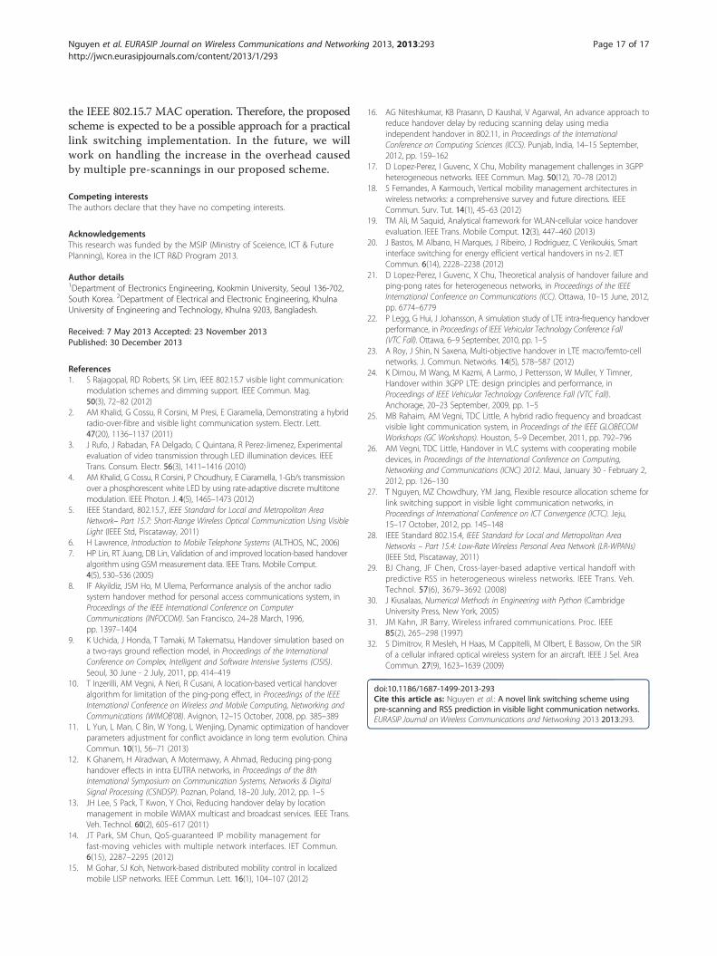
also affects the unnecessary link switching ratio, as shownin Figure 10. The unnecessary link switching ratio is a par-ameter used to assess the performance of a link switchingscheme in terms of coping with the ping-pong effect. Theconventional hard and soft link switching schemes onlychoose the next serving transmitters for user devicesbased on the RSS values of neighboring transmitters at theselection time, so their unnecessary link switching ratiosare equal. The simulation results shown in Figure 10 helpin validating this assessment. Utilizing the knowledge ofprevious RSS values of neighboring transmitters combinedwith the RSS prediction scheme, our proposed schemehelps in choosing the next serving transmitters for userdevices more precisely, so the unnecessary link switchingratio is decreased as well.To deeply evaluate the performance of our proposed
scheme compared to the conventional hard and soft linkswitching schemes, we apply a hysteresis margin-basedmethod to the three schemes. In the hysteresis margin-based method, the best neighboring transmitter is chosento be the next serving transmitter of a user device if itsRSS value is larger than the RSS value of the current serv-ing transmitter of the user device by a hysteresis margin.Using the hysteresis margin-based method, the valuesof the Rnls,x(i) and Rx(i,j) probabilities are respectivelymodified as
Rhystnls;x ið Þ ¼ R Pr x; ið Þ≥ LS thrð Þð j j Pr;pred j; tnþ1ð Þ−Pr x; ið Þ < Hys thr
� ��
¼Z∞−∞
Q
LS thrPt
− �H x; ið Þσ
0BB@
1CCA:
1ffiffiffiffiffiffi2π
pσe−
G2o2σ2dGo
þZ∞−∞
Q
�H x; jð Þ−Hys thr þ Pr x; ið ÞγPt
σ
0BB@
1CCA:
1ffiffiffiffiffiffi2π
pσe−
G2o2σ2dGo
ð50Þ
and
Rhystx i; jð Þ ¼ R½ Pr;pred j; tnþ1ð Þ‐Pr x; ið Þ ≥Hys thr� �
& Pr;pred j; tnþ1ð Þ > Pr;pred k; tnþ1ð Þ� �& Pr;pred j; tnþ1ð Þ‐Pr j; tnð Þ > 0� ��
¼Z∞−∞
Q
Hys thr þ Pr x; ið ÞγPt
− �H x; jð Þσ
0BB@
1CCA
�Y
k≠j;∀k;j∈Nt
QH x; kð Þ− �H x; jð Þ
σ
�:
1ffiffiffiffiffiffi2π
pσe−
G2o2σ2dGo
ð51Þ
where Hys_thr is a predefined value of the hysteresismargin.
40 80 120 1600
100
200
300
Link
sw
itchi
ng d
elay
(m
s)
Number of transmitters
Conventional hardProposed schemeConventional soft
Figure 7 Simulation results of the link switching delay versus number of transmitters.
Nguyen et al. EURASIP Journal on Wireless Communications and Networking 2013, 2013:293 Page 14 of 17http://jwcn.eurasipjournals.com/content/2013/1/293
The hysteresis margin method can help reduce theunnecessary link switching ratio that is validated bythe simulation results shown in Figure 10 (the value ofHys_thr is set to 4 dB in our experiments). However,the use of a hysteresis margin results in an increase inthe outage probability, which is made evident by thenumerical results shown in Figures 11 and 12. In Figure 11,the outage probabilities of the three schemes according
2 40.4
0.6
0.8
1.0
Link
sw
itchi
ng c
all d
ropp
ing
prob
abili
ty
New call arri
ConveProposConve
Figure 8 Numerical results of the link switching call dropping probab
to the normalized distance are represented. In this ex-periment, the new call arrival rate is set to 1 call/s. Inthe region near the transmitters, where the normalizeddistance is less than or equal to 0.2, the outage prob-abilities of three schemes are almost equal to zero. Theoutage probability of our proposed scheme is lower thanthose of the two other schemes, even in the boundaryarea. In the cases of both using as well as not using the
6 8 10
val rate (calls/s)
ntional harded scheme
ntional soft
ility under various new call arrival rates.
2 4 6 8 100.4
0.6
0.8
1.0
New
cal
l blo
ckin
g pr
obab
ility
New call arrival rate (calls/s)
Conventional hardProposed schemeConventional soft
Figure 9 Numerical results of the new call blocking probability under various new call arrival rates.
Nguyen et al. EURASIP Journal on Wireless Communications and Networking 2013, 2013:293 Page 15 of 17http://jwcn.eurasipjournals.com/content/2013/1/293
hysteresis margin method, the conventional hard linkswitching scheme achieves the highest outage prob-ability when the normalized distance is less than orequal to 0.8.The new call arrival rate affects the link switching call
dropping probability, so the outage probability is af-fected as well. Figure 12 shows the impact of the newcall arrival rate on the outage probability when the
40 80
0.10
0.15
0.20
0.25
Unn
eces
sary
link
sw
itchi
ng r
atio
Number o
Conventional hardConventional hard_wProposed schemeProposed scheme_wConventional softConventional soft_w
Figure 10 Comparison of the unnecessary link switching ratio using s
normalized distance is equal to 0.5. The new call ar-rival rate affects the conventional soft link switchingscheme more seriously than those two schemes. Inthe case when the hysteresis margin method is notused, when the new call arrival rate is less than orequal to 3 calls/s, the conventional hard link switch-ing achieves the highest outage probability. However,when the new call arrival rate is higher than 3 calls/s,
120 160
f transmitters
ith hyst
ith hyst
ith hyst
imulation results.

0.0 0.2 0.4 0.6 0.8 1.00.00
0.02
0.04
0.06
0.08
Out
age
prob
abili
ty
Normalized distance
Conventional hardConventional hard_with hystProposed schemeProposed scheme_with hystConventional softConventional soft_with hyst
Figure 11 Numerical results of the outage probability according to normalized distance.
Nguyen et al. EURASIP Journal on Wireless Communications and Networking 2013, 2013:293 Page 16 of 17http://jwcn.eurasipjournals.com/content/2013/1/293
the outage probability of the conventional soft link switch-ing scheme becomes the highest.
5. ConclusionsThis paper has presented a novel hard link switchingscheme, which overcomes the drawbacks of conventionalhard and soft link switching schemes, for VLC networks.The proposed scheme uses pre-scanning and predictive
2 40.00
0.01
0.02
0.03
0.04
0.05
0.06
Out
age
prob
abili
ty
New call arr
ConConProProConCon
Figure 12 Numerical results of the outage probability under various
RSS methods to reduce the link switching delay and theunnecessary link switching ratio. In addition, the SINRand the outage probability are analyzed with respect tothe link switching situation in a VLC environment. Theproposed scheme achieves a lower outage probabilitycompared to the conventional hard and soft link switch-ing schemes. To utilize our proposed scheme, there isno need to change the hardware of the user devices and
6 8 10
ival rate (calls/s)
ventional hardventional hard_with hystposed schemeposed scheme_with hystventional softventional soft_with hyst
new call arrival rates.
Nguyen et al. EURASIP Journal on Wireless Communications and Networking 2013, 2013:293 Page 17 of 17http://jwcn.eurasipjournals.com/content/2013/1/293
the IEEE 802.15.7 MAC operation. Therefore, the proposedscheme is expected to be a possible approach for a practicallink switching implementation. In the future, we willwork on handling the increase in the overhead causedby multiple pre-scannings in our proposed scheme.
Competing interestsThe authors declare that they have no competing interests.
AcknowledgementsThis research was funded by the MSIP (Ministry of Sceience, ICT & FuturePlanning), Korea in the ICT R&D Program 2013.
Author details1Department of Electronics Engineering, Kookmin University, Seoul 136-702,South Korea. 2Department of Electrical and Electronic Engineering, KhulnaUniversity of Engineering and Technology, Khulna 9203, Bangladesh.
Received: 7 May 2013 Accepted: 23 November 2013Published: 30 December 2013
References1. S Rajagopal, RD Roberts, SK Lim, IEEE 802.15.7 visible light communication:
modulation schemes and dimming support. IEEE Commun. Mag.50(3), 72–82 (2012)
2. AM Khalid, G Cossu, R Corsini, M Presi, E Ciaramelia, Demonstrating a hybridradio-over-fibre and visible light communication system. Electr. Lett.47(20), 1136–1137 (2011)
3. J Rufo, J Rabadan, FA Delgado, C Quintana, R Perez-Jimenez, Experimentalevaluation of video transmission through LED illumination devices. IEEETrans. Consum. Electr. 56(3), 1411–1416 (2010)
4. AM Khalid, G Cossu, R Corsini, P Choudhury, E Ciaramella, 1-Gb/s transmissionover a phosphorescent white LED by using rate-adaptive discrete multitonemodulation. IEEE Photon. J. 4(5), 1465–1473 (2012)
5. IEEE Standard, 802.15.7, IEEE Standard for Local and Metropolitan AreaNetwork– Part 15.7: Short-Range Wireless Optical Communication Using VisibleLight (IEEE Std, Piscataway, 2011)
6. H Lawrence, Introduction to Mobile Telephone Systems (ALTHOS, NC, 2006)7. HP Lin, RT Juang, DB Lin, Validation of and improved location-based handover
algorithm using GSM measurement data. IEEE Trans. Mobile Comput.4(5), 530–536 (2005)
8. IF Akyildiz, JSM Ho, M Ulema, Performance analysis of the anchor radiosystem handover method for personal access communications system, inProceedings of the IEEE International Conference on ComputerCommunications (INFOCOM). San Francisco, 24–28 March, 1996,pp. 1397–1404
9. K Uchida, J Honda, T Tamaki, M Takematsu, Handover simulation based ona two-rays ground reflection model, in Proceedings of the InternationalConference on Complex, Intelligent and Software Intensive Systems (CISIS).Seoul, 30 June - 2 July, 2011, pp. 414–419
10. T Inzerilli, AM Vegni, A Neri, R Cusani, A location-based vertical handoveralgorithm for limitation of the ping-pong effect, in Proceedings of the IEEEInternational Conference on Wireless and Mobile Computing, Networking andCommunications (WIMOB’08). Avignon, 12–15 October, 2008, pp. 385–389
11. L Yun, L Man, C Bin, W Yong, L Wenjing, Dynamic optimization of handoverparameters adjustment for conflict avoidance in long term evolution. ChinaCommun. 10(1), 56–71 (2013)
12. K Ghanem, H Alradwan, A Motermawy, A Ahmad, Reducing ping-ponghandover effects in intra EUTRA networks, in Proceedings of the 8thInternational Symposium on Communication Systems, Networks & DigitalSignal Processing (CSNDSP). Poznan, Poland, 18–20 July, 2012, pp. 1–5
13. JH Lee, S Pack, T Kwon, Y Choi, Reducing handover delay by locationmanagement in mobile WiMAX multicast and broadcast services. IEEE Trans.Veh. Technol. 60(2), 605–617 (2011)
14. JT Park, SM Chun, QoS-guaranteed IP mobility management forfast-moving vehicles with multiple network interfaces. IET Commun.6(15), 2287–2295 (2012)
15. M Gohar, SJ Koh, Network-based distributed mobility control in localizedmobile LISP networks. IEEE Commun. Lett. 16(1), 104–107 (2012)
16. AG Niteshkumar, KB Prasann, D Kaushal, V Agarwal, An advance approach toreduce handover delay by reducing scanning delay using mediaindependent handover in 802.11, in Proceedings of the InternationalConference on Computing Sciences (ICCS). Punjab, India, 14–15 September,2012, pp. 159–162
17. D Lopez-Perez, I Guvenc, X Chu, Mobility management challenges in 3GPPheterogeneous networks. IEEE Commun. Mag. 50(12), 70–78 (2012)
18. S Fernandes, A Karmouch, Vertical mobility management architectures inwireless networks: a comprehensive survey and future directions. IEEECommun. Surv. Tut. 14(1), 45–63 (2012)
19. TM Ali, M Saquid, Analytical framework for WLAN-cellular voice handoverevaluation. IEEE Trans. Mobile Comput. 12(3), 447–460 (2013)
20. J Bastos, M Albano, H Marques, J Ribeiro, J Rodriguez, C Verikoukis, Smartinterface switching for energy efficient vertical handovers in ns-2. IETCommun. 6(14), 2228–2238 (2012)
21. D Lopez-Perez, I Guvenc, X Chu, Theoretical analysis of handover failure andping-pong rates for heterogeneous networks, in Proceedings of the IEEEInternational Conference on Communications (ICC). Ottawa, 10–15 June, 2012,pp. 6774–6779
22. P Legg, G Hui, J Johansson, A simulation study of LTE intra-frequency handoverperformance, in Proceedings of IEEE Vehicular Technology Conference Fall(VTC Fall). Ottawa, 6–9 September, 2010, pp. 1–5
23. A Roy, J Shin, N Saxena, Multi-objective handover in LTE macro/femto-cellnetworks. J. Commun. Networks. 14(5), 578–587 (2012)
24. K Dimou, M Wang, M Kazmi, A Larmo, J Pettersson, W Muller, Y Timner,Handover within 3GPP LTE: design principles and performance, inProceedings of IEEE Vehicular Technology Conference Fall (VTC Fall).Anchorage, 20–23 September, 2009, pp. 1–5
25. MB Rahaim, AM Vegni, TDC Little, A hybrid radio frequency and broadcastvisible light communication system, in Proceedings of the IEEE GLOBECOMWorkshops (GC Workshops). Houston, 5–9 December, 2011, pp. 792–796
26. AM Vegni, TDC Little, Handover in VLC systems with cooperating mobiledevices, in Proceedings of the International Conference on Computing,Networking and Communications (ICNC) 2012. Maui, January 30 - February 2,2012, pp. 126–130
27. T Nguyen, MZ Chowdhury, YM Jang, Flexible resource allocation scheme forlink switching support in visible light communication networks, inProceedings of International Conference on ICT Convergence (ICTC). Jeju,15–17 October, 2012, pp. 145–148
28. IEEE Standard 802.15.4, IEEE Standard for Local and Metropolitan AreaNetworks – Part 15.4: Low-Rate Wireless Personal Area Network (LR-WPANs)(IEEE Std, Piscataway, 2011)
29. BJ Chang, JF Chen, Cross-layer-based adaptive vertical handoff withpredictive RSS in heterogeneous wireless networks. IEEE Trans. Veh.Technol. 57(6), 3679–3692 (2008)
30. J Kiusalaas, Numerical Methods in Engineering with Python (CambridgeUniversity Press, New York, 2005)
31. JM Kahn, JR Barry, Wireless infrared communications. Proc. IEEE85(2), 265–298 (1997)
32. S Dimitrov, R Mesleh, H Haas, M Cappitelli, M Olbert, E Bassow, On the SIRof a cellular infrared optical wireless system for an aircraft. IEEE J Sel. AreaCommun. 27(9), 1623–1639 (2009)
doi:10.1186/1687-1499-2013-293Cite this article as: Nguyen et al.: A novel link switching scheme usingpre-scanning and RSS prediction in visible light communication networks.EURASIP Journal on Wireless Communications and Networking 2013 2013:293.