Embed Size (px)
Citation preview

Research ArticlePolarization Division Multiplexing of OFDM Radio-over-FiberSignals in Passive Optical Networks
Maria Morant, Joaquin Pérez, and Roberto Llorente
Universitat Politecnica de Valencia, Camino de Vera s/n, 46022 Valencia, Spain
Correspondence should be addressed to Maria Morant; [email protected]
Received 31 July 2013; Accepted 13 January 2014; Published 27 February 2014
Academic Editor: Zoran Ikonic
Copyright © 2014 Maria Morant et al. This is an open access article distributed under the Creative Commons Attribution License,which permits unrestricted use, distribution, and reproduction in any medium, provided the original work is properly cited.
This paper describes the state-of-the-art of polarization multiplexing for optical networks transmission. The use of polarizationdivision multiplexing (PDM) permits to multiply the user capacity and increase the spectral efficiency. Combining PDM andorthogonal frequency division multiplexed (OFDM) modulation allows maximizing the optical transmission capacity. Theexperimental demonstration of transmitting OFDM signals following ECMA-368 ultrawide band (UWB) standard in radio-over-fiber using PDM in passive optical networks is herein reported. The impact of cross-polarization and cochannel crosstalk isevaluated experimentally in a three-user OFDM-UWB subcarrier multiplexed (SCM) configuration per polarization. Each SCMuses up to three OFDM-UWB channels of 200Mbit/s each, achieving an aggregated bitrate of 1.2 Gbit/s with 0.76 bit/s/Hz spectralefficiency when using PDM transmission. The experimental results for the polarization-multiplexed SCM indicate that a 4 dBadditional polarization crosstalk interference can be expected compared to a nonpolarization-multiplexed transmission systemwhich translates to 2.4 dB EVM penalty in the UWB signals. The successful PDM transmission of SCM multiuser OFDM-UWBover a passive optical network of 25 km standard-single mode fiber (SSMF) reach is demonstrated.
1. Introduction
The ever-growing transmission capacity demand in opticaltransmission systemshas brought out the necessity of increas-ing the spectral efficiency employing different transmissiontechniques. Several approaches have been proposed to date inorder to increase the transmission capacity, that is, bitrate bynumber of users. In particular, the use of efficientmodulationformats altogether with advanced multiplexing techniqueshas been indicated as an interesting approach.
New modulation formats have been reported suitable forproviding higher bitrate to the final customer. Especially,orthogonal frequency division multiplexing (OFDM) modu-lation has been adopted by several wireless standards such as3GPP long-term evolution (LTE) or IEEE 802.16 worldwideinteroperability for microwave access (WiMAX), betweenothers. Also, new transmission technologies based on spread-ing techniques such as ultrawide band (UWB) use OFDMmodulation.These signals can achieve high spectral efficiencywhen using several hundreds of OFDM subcarriers. Anotheradvantage of the OFDM signals is the capability to correct
multipath fading thanks to the cyclic prefix of the OFDMsignal. For these reasons, OFDM suitability for optical com-munications has attracted a lot of attention in the fiber-opticcommunity in the last decade [1].
Optical communication systems are developing rapidlyto provide high-bitrate services to the final customer usingfiber-to-the-home (FTTH) networks. Moreover, as the useof wireless services employing OFDM modulation is widelyextended, radio-over-fiber has been appointed as a rapidand cost-effective solution to facilitate the deployment ofintegrated access networks and to reach customer premiseswith high bit rate wireless signals [2]. Using a radio-over-fibersystem, we can transport different OFDM-based wirelesssignals in its native format and regulated frequency band.
However, the ever-growing wireless services demandjointly with the radio spectral scarcity pointed out thenecessity of increasing the spectral efficiency, combining newmodulation formats with advanced multiplexing techniques.
One optical technique used to improve the efficiencyof optical communication systems is polarization divisionmultiplexing (PDM). The use of PDM permits multiplying
Hindawi Publishing CorporationAdvances in Optical TechnologiesVolume 2014, Article ID 269524, 9 pageshttp://dx.doi.org/10.1155/2014/269524
2 Advances in Optical Technologies
1
0
−
−1−1
0
1 1
0
−1
+S1 +S2
+S3
−1
−
0
1
−1
−
0
1
+S1 +S2
+S3
∘
Linear +45∘
Circularlef-handed
Ellipticalright-handed
Pol. A
Pol. B90∘
Pol. A
Pol. B
f
Ch1A Ch2A
WiMAX
Pol. A
Pol. B
f
Ch1A Ch2A UWB
UWB
Ch1B Ch2B Ch3A
Ch3B
· · ·
· · ·
(a) (b)
(c)
(d)
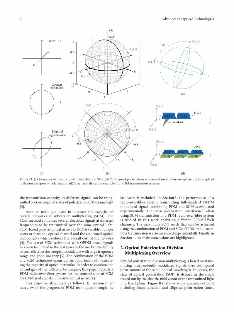
Figure 1: (a) Examples of linear, circular, and elliptical SOP. (b) Orthogonal polarization representation in Poincare sphere. (c) Example oforthogonal ellipses of polarization. (d) Spectrum allocation examples for PDM transmission systems.
the transmission capacity, as different signals can be trans-mitted over orthogonal states of polarization of the same light[3].
Another technique used to increase the capacity ofoptical networks is subcarrier multiplexing (SCM). TheSCM method combines several electrical signals at differentfrequencies to be transmitted over the same optical light.SCM-based passive optical networks (PONs) enable multipleusers to share the optical channel and the associated opticalcomponents which reduces the overall cost of the network[4]. The use of SCM techniques with OFDM-based signalshas been facilitated in the last years by the market availabilityof cost-effective electroopticmodulators with large frequencyrange and good linearity [5]. The combination of the PDMand SCM techniques opens up the opportunity of maximiz-ing the capacity of optical networks. In order to combine theadvantages of the different techniques; this paper reports aPDM radio-over-fiber system for the transmission of SCMOFDM-based signals in passive optical networks.
This paper is structured as follows. In Section 2, anoverview of the progress of PDM techniques through the
last years is included. In Section 3, the performance of aradio-over-fiber system transmitting full-standard OFDMmodulated signals combining PDM and SCM is evaluatedexperimentally. The cross-polarization interference whenusing SCM transmission in a PDM radio-over-fiber systemis studied in this work analyzing different OFDM-UWBchannels. The maximum PON reach that can be achievedusing the combination of PDM and SCMOFDM radio-over-fiber transmission is alsomeasured experimentally. Finally, inSection 4, the main conclusions are highlighted.
2. Optical Polarization DivisionMultiplexing Overview
Optical polarization division multiplexing is based on trans-mitting independently modulated signals over orthogonalpolarizations of the same optical wavelength. In optics, thestate of optical polarization (SOP) is defined as the shapetraced out by the electric-field vector of the transmitted lightin a fixed plane. Figure 1(a) shows some examples of SOP,including linear, circular, and elliptical polarization states.

Advances in Optical Technologies 3
Linear polarization is obtained when the direction of theelectric vector is constant (the electric-field vectors alongwith 𝐸
𝑥and 𝐸
𝑦directions are in phase). When 𝐸
𝑥and 𝐸
𝑦
are exactly ninety degrees out of phase, we have circularpolarization. There are right-handed or left-handed circu-lar/elliptical polarizations, depending on which direction theelectric-field vector rotates, that is, if the electric-field vectoris seen rotating clockwise or counterclockwise.
Figure 1(b) shows an example of two orthogonal SOPrepresented in the Poincare sphere. The polarization state isdefined using the Stokes parameters that can be representedin the Poincare sphere over the three-dimensional vectorof Cartesian coordinates called 𝑆
1, 𝑆2, and 𝑆
3. The right
circular polarization pole (RCP) is included in the sphere forreference. In the example presented in Figures 1(b) and 1(c),the polarization states were measured with Optellios PS2300optical polarization analyzer. As it is described in Figure 1(b),two polarizations are orthogonal if they are separated by 180∘in the Poincare sphere. Figure 1(c) shows the polarizationellipses for each polarization. In the representation of polar-ization ellipses, two states are orthogonal if they have a 90∘phase shift (as sine and cosine).
The polarization multiplexing method can be explainedfrom the similarity with the techniques used in microwavecommunications. In wireless links, the user bandwidth canbe improved if two orthogonally polarized radio frequencysignals are transmitted. At the receiver, two antennas withdifferent polarization and orientation are used to discrimi-nate each of the signals. The same occurs in optical systems:at the receiver, the two orthogonal states of polarization aredetected, obtaining each of the modulated signals indepen-dently. If the orthogonality is maintained through the opticalsystem, at the receiver, each of the modulated signals canbe recovered. But SOP orthogonality is degraded due to thepropagation in optical networks [6] due to stress in the glassfiber (bending and twisting), moving the fiber, or even ambi-ent temperature changes. For this reason, it is important toevaluate if the crosstalk due to cross-polarization interferenceis limiting the performance at the receiver.
Several techniques have been proposed to mitigate theinterference coming from cross-polarization. One techniqueis based on frequency interleaving of the adjacent channelsthat are orthogonally polarized [7]. Polarization interleavemultiplexing systems have achieved experimentally up to1.6 bit/s/Hz spectrum efficiency as demonstrated by Soto-bayashi et al. [8].
The main impairments suffered by optical PDM systemsare due to cross-phase modulation (XPM) [9] and polariza-tion-mode dispersion (PMD) [10]. Nelson et al. [11] assessedthe impairments caused by first-order PMD in the fiber usinga non-return-to-zero (NRZ) polarization-multiplexed systemwith 40Gb/s per channel and 0.8 bit/s/Hz spectral efficiency.The measured system penalty of 1 dB in instantaneous dif-ferential group delay (DGD) pointed out that polarization-multiplexed systems are five times more sensitive to PMDcompared with nonpolarization-multiplexed systems due tocrosstalk [11]. However, a 121.9 Gb/s polarization-multiplexedtransmission using coherent detection was demonstratedby Jansen et al. [12] with 4 OFDM channels at 2 bit/s/Hz
spectral efficiency over 1000 km of standard-single modefiber (SSMF).
The receiver of PDM-OFDM system can be seen as amul-tiple inputmultiple output (MIMO) system 2×2.Thus, digitalsignal processing (DSP) algorithm based on MIMO process-ing can be used for improving the optical transmission, asproposed in the literature for wireless communications [13].Recently, PDM systems have been demonstrated as a viablesolution for fully standardized wireless MIMO provisionusing radio-over-fiber polarization-multiplexed long-reachoptical transmission [14]. Two different optical detectionapproaches can be implemented: direct or coherent detection.For simplicity of the receiver, in this paper, we will focuson direct detection, but the network reach could be furtherextended using coherent detection or adding MIMO digi-tal processing. For example, a PON architecture of 20 kmof SSMF was demonstrated with a 40Gb/s PDM-OFDMtransmission includingMIMOdigital signal processing at thereceiver [15].
3. PDM OFDM-UWB Radio-over-FiberTransmission System
As it was introduced previously, OFDM has been appointedas an effective modulation scheme to increase the user bitrateand spectral efficiency. Although the OFDM signal needsadditional overheads due to the cyclic prefix, the trainingsymbols for channel estimation, and pilot subcarriers forphase noise compensation, the performance ofOFDMsignalsis more robust to multipath fading and to the impairmentscaused by chromatic dispersion or PMD. For these reasons,using OFDM signals can increase the efficiency and theflexibility of access optical networks while reducing imple-mentation cost. However, due to the limited technology ofcommercial digital-to-analog converters (DAC) [15], in orderto obtain very high bitrates, the combination of PDM andOFDM systems is an interesting solution.
As OFDM signals are currently used by most of the user-orientedwireless standards (such asDVB-T,WiMAX, LTE, orUWB), we propose to combine PDM distribution in a radio-over-fiber system transmitting full-standard OFDM signalsin its native format. The OFDM signals is transmitted in thecorresponding regulated frequency band, so no upconversionor frequency shift is needed at the receiver, which simplifiesthe optical network terminator at customer premises [16]and, in consequence, reduces the cost for both the final userand the operator. Moreover, the radio-over-fiber systems aretransparent to the signals that are transmitted through thenetwork, which enables including new signals to the networkas soon as they appear in the market [17]. In this case, weselected OFDM-UWB signals for the evaluation of the PDMtransmission in passive optical networks. UWB radio oper-ates in a large frequency range (i.e., from 3.1 to 10.6GHz) andemits very low power spectral densities (−41.3 dBm/MHz)to minimize the interference over other radio services [18].In ECMA standard 368, the UWB band is divided in 12channels of 528MHz bandwidth each for OFDM signals with128 subcarriers [19]. These are also called multiband OFDMsignals. The growing interest of UWB technology focuses
4 Advances in Optical Technologies
DSA 80000BPIN
Amplifier
(1)
(2)
MZ-EOM1MZ-EOM2
EDFA VOA
(3) (4)
(5)
(6)
AmplifierUWB TX2
Pol. A
Pol. B
UWB TX1
PC PC
PCPC PC
Amplifier
SSMF Pol. A
Pol. B
EVM
(b)
Pol. ATFC5A
TFC5BTFC6A TFC7A
TFC6B TFC7B
Pol. A
TFC6ATFC7B
Pol. A
Pol. BPol. B
Pol. B
TFC6A TFC7ATFC6B TFC7B
1 user: User number 1
2 users:
3 users:
f
f
fPol. A
Pol. B
TX1:TX2:
TX1:TX2:
1:2:
Central office
User premises
User
User number 1 User number 2
(a)
90∘ L
PBC PBS
𝜆 = 1555nm
number 1User
number 2User
number 3
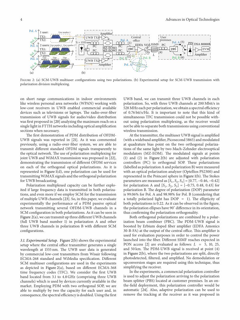
Figure 2: (a) SCM-UWB multiuser configurations using two polarizations. (b) Experimental setup for SCM-UWB transmission withpolarization division multiplexing.
on short range communications in indoor environmentslike wireless personal area networks (WPAN) working withlow-cost receivers in UWB enabled commercial availabledevices such as televisions or laptops. The radio-over-fibertransmission of UWB signals for audio/video distributionwas first proposed in [20] analyzing the maximum reach on asingle light in FTTHnetworks including optical amplificationsections when necessary.
The first demonstration of PDM distribution of OFDM-UWB signals was reported in [21]. As it was commentedpreviously, using a radio-over-fiber system, we are able totransmit different standard OFDM signals transparently tothe optical network. The use of polarization multiplexing forjoint UWB and WiMAX transmission was proposed in [22],demonstrating the transmission of different OFDM serviceson each of the orthogonal optical polarizations. As it isrepresented in Figure 1(d), one polarization can be used fortransmittingWiMAX signals and the orthogonal polarizationfor UWB broadcasting.
Polarization multiplexed capacity can be further explo-ited if large frequency data is transmitted in both polariza-tions, and even more if we employ SCM for the transmissionof multiple UWB channels [23]. So, in this paper, we evaluateexperimentally the performance of a PDM passive opticalnetwork transmitting several OFDM-UWB channels in aSCM configuration in both polarizations. As it can be seen inFigure 2(a), we can transmit up three differentUWBchannels(full UWB band number 1) in polarization A and otherthree UWB channels in polarization B with different SCMconfigurations.
3.1. Experimental Setup. Figure 2(b) shows the experimentalsetup where the central office transmitter generates a singlewavelength at 1555 nm. The UWB user data is generatedby commercial low-cost transmitters from Wisair followingECMA-268 standard and WiMedia specification. DifferentSCM multiuser configurations are used in the experimentsas depicted in Figure 2(a), based on different ECMA-368time frequency codes (TFC). We consider the first UWBband located from 3.1 to 4.8GHz (comprising three UWBchannels) which is used by devices currently available in themarket. Employing PDM with two orthogonal SOP, we areable to multiply by two the capacity for each user and, inconsequence, the spectral efficiency is doubled. Using the first
UWB band, we can transmit three UWB channels in eachpolarization. So, with three UWB channels at 200Mbit/s in528MHz each per polarization, we obtain a spectral efficiencyof 0.76 bit/s/Hz. It is important to note that this kind ofsimultaneous TFC transmission could not be possible with-out using polarization multiplexing, as the receiver wouldnot be able to separate both transmissions using conventionalwireless transmission.
At the transmitter, the multiuser UWB signal is amplified(with a wideband amplifier, Picosecond 5865) andmodulatedat quadrature bias point on the two orthogonal polariza-tions of the same light by two Mach-Zehnder electroopticalmodulators (MZ-EOM). The modulated signals at points(1) and (2) in Figure 2(b) are adjusted with polarizationcontrollers (PC) to orthogonal SOP. These polarizations(labelled as polarizationA and polarization B)weremeasuredwith an optical polarization analyzer (Optellios PS2300) andrepresented in the Poincare sphere in Figure 1(b). The Stokesparameters are measured as [𝑆
1, 𝑆2, 𝑆3] = [0.77, −0.46, −0.42]
for polarization A and [𝑆1, 𝑆2, 𝑆3] = [−0.75, 0.48, 0.43] for
polarization B. The degree of polarization (DOP) parameteris 99.06% for Pol. A and 98.98% for Pol. B (considering thata totally polarized light has DOP = 1). The ellipticity ofboth polarizations is 0.22. As it can be observed in the figure,the polarization ellipses have 90∘ difference in its orientation,thus confirming the polarization orthogonality.
Both orthogonal polarizations are combined by a polar-ization beam combiner (PBC). The PDM-UWB signal isboosted by Erbium doped fiber amplifier (EDFA Amonics30-B-FA) at the output of the central office. This amplifier isused for evaluation purposes in order to control the powerlaunched into the fiber. Different SSMF reaches expected inPON access [2] are evaluated as follows: 𝐿 = 5, 10, 25,and 50 km. The PDM-UWB signal is received at point (4)in Figure 2(b), where the two polarizations are split, directlyphotodetected, filtered, and amplified. No demodulation orupconversion stages are required using this technique, thussimplifying the receiver.
In the experiments, a commercial polarization controlleris used to adjust the polarization arriving to the polarizationbeam splitter (PBS) located at customer premises. In an on-the-field deployment, this polarization controller would beautomatic [24]. Also, adaptive polarization can be used toremove the tracking at the receiver as it was proposed in
Advances in Optical Technologies 5
(a)
(b)
Crosstalk Pol. A discrimination
Frequency (GHz)
UWB on Pol. A in (5) UWB on Pol. B in (5)Po
wer
(dBm
)
−90
−80
−70
−60
−50
−40
Pow
er (d
Bm)
−90
−80
−70
−60
−50
−40
3.0 3.5 4.0 4.5 5.0
Frequency (GHz)3.0 3.5 4.0 4.5 5.0
Crosstalk−78dBm
Noise:−82dBm
30 dB
User number 1
User number 2
User number 3
UWB on Pol. A in (6) UWB on Pol. B in (6)
Pow
er (d
Bm)
−90
−80
−70
−60
−50
−40
Pow
er (d
Bm)
−90
−80
−70
−60
−50
−40
Frequency (GHz)3.0 3.5 4.0 4.5 5.0
Frequency (GHz)3.0 3.5 4.0 4.5 5.0
Crosstalk Pol. Bdiscrimination
33dB
User number 1
User number 2
User number 3
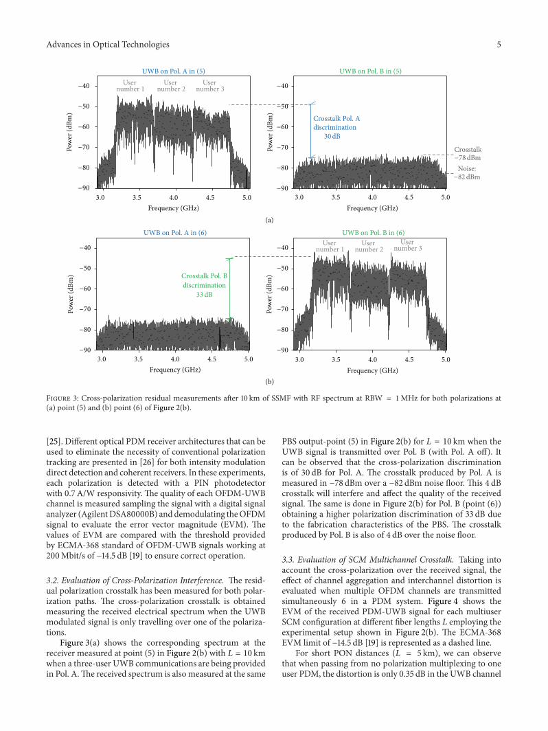
Figure 3: Cross-polarization residual measurements after 10 km of SSMF with RF spectrum at RBW = 1MHz for both polarizations at(a) point (5) and (b) point (6) of Figure 2(b).
[25]. Different optical PDM receiver architectures that can beused to eliminate the necessity of conventional polarizationtracking are presented in [26] for both intensity modulationdirect detection and coherent receivers. In these experiments,each polarization is detected with a PIN photodetectorwith 0.7 A/W responsivity. The quality of each OFDM-UWBchannel is measured sampling the signal with a digital signalanalyzer (AgilentDSA80000B) anddemodulating theOFDMsignal to evaluate the error vector magnitude (EVM). Thevalues of EVM are compared with the threshold providedby ECMA-368 standard of OFDM-UWB signals working at200Mbit/s of −14.5 dB [19] to ensure correct operation.
3.2. Evaluation of Cross-Polarization Interference. The resid-ual polarization crosstalk has been measured for both polar-ization paths. The cross-polarization crosstalk is obtainedmeasuring the received electrical spectrum when the UWBmodulated signal is only travelling over one of the polariza-tions.
Figure 3(a) shows the corresponding spectrum at thereceiver measured at point (5) in Figure 2(b) with 𝐿 = 10 kmwhen a three-user UWB communications are being providedin Pol. A.The received spectrum is also measured at the same
PBS output-point (5) in Figure 2(b) for 𝐿 = 10 km when theUWB signal is transmitted over Pol. B (with Pol. A off). Itcan be observed that the cross-polarization discriminationis of 30 dB for Pol. A. The crosstalk produced by Pol. A ismeasured in −78 dBm over a −82 dBm noise floor. This 4 dBcrosstalk will interfere and affect the quality of the receivedsignal. The same is done in Figure 2(b) for Pol. B (point (6))obtaining a higher polarization discrimination of 33 dB dueto the fabrication characteristics of the PBS. The crosstalkproduced by Pol. B is also of 4 dB over the noise floor.
3.3. Evaluation of SCM Multichannel Crosstalk. Taking intoaccount the cross-polarization over the received signal, theeffect of channel aggregation and interchannel distortion isevaluated when multiple OFDM channels are transmittedsimultaneously 6 in a PDM system. Figure 4 shows theEVM of the received PDM-UWB signal for each multiuserSCM configuration at different fiber lengths 𝐿 employing theexperimental setup shown in Figure 2(b). The ECMA-368EVM limit of −14.5 dB [19] is represented as a dashed line.
For short PON distances (𝐿 = 5 km), we can observethat when passing from no polarization multiplexing to oneuser PDM, the distortion is only 0.35 dB in the UWB channel

6 Advances in Optical Technologies
−21
−20
−19
−18
−17
−16
−15
−14
−13
EVM
(dB)
NoPDM
1 userPDM
L = 5km
A2 usersPDM
B3 usersPDM
A B
TFC6TFC7TFC5
(a)
TFC6TFC7TFC5
−21
−20
−19
−18
−17
−16
−15
−14
−13
EVM
(dB)
NoPDM
1 userPDM
L = 10km
A2 usersPDM
B3 usersPDM
A B
(b)
TFC6TFC7TFC5
−21
−20
−19
−18
−17
−16
−15
−14
−13
EVM
(dB)
NoPDM
1 userPDM
L = 25km
A2 usersPDM
B3 usersPDM
A B
(c)
Figure 4: PDM-UWB EVM performance of each UWB channel in different SCMmultiuser configurations versus PON reach: (a) 𝐿 = 5 km,(b) 𝐿 = 10 km, and (c) 𝐿 = 25 km.
No PDM 1 user PDM 2 users PDM 3 users PDM
EVM = −20.27 dB EVM = −19.85dB EVM = −19.43dB EVM = −18.52dB
L=5
km
(a)
EVM = −18.24 dB EVM = −17.02dB EVM = −15.89dB EVM = −15.24dB
L=25
km
(b)
Figure 5: Constellations of the center channel TFC6 with different SCM multiuser configurations using or not PDM for (a) 𝐿 = 5 km and(b) 𝐿 = 25 km. 24UWB symbols represented the following: blue dots indicate data symbols and red dots correspond to pilot and guardsymbols.
working at TFC6. When adding a second user (cochannelinterference), the EVM is 0.42 dB worse than a single userwith different TFC. Finally, transmitting the three-user UWBchannels, the EVM in TFC6 is −18.52 dB (0.91 dB worsethan two users with PDM). For longer distances (𝐿 =25 km), the EVM penalty is of 1.2 dB from no polariza-tion to single user PDM and of 3 dB to three users usingPDM. Symbol degradation can be seen in the quadrature
phase shift keying (QPSK) constellations represented inFigure 5.
3.4. Evaluation of Maximum Reach in PON. Once the effectof multiuser transmission is evaluated, the SCM-UWB per-formance after 𝐿 km repeater-less optical transmission inPDMnetworks is studied using different launch power levels.The experimental setup was shown in Figure 2(b), where a

Advances in Optical Technologies 7
No PDM
Pol. BPol. A
5 10 25 50
EVM
(dB)
TFC5
L (km)
ECMA-368 limit
−24
−20
−16
−12
−8
−4
(a)
No PDM
Pol. BPol. A
TFC6
5 10 25 50L (km)
EVM
(dB)
−24
−20
−16
−12
−8
−4
(b)
No PDM
Pol. BPol. A
TFC7
5 10 25 50L (km)
EVM
(dB)
−24
−20
−16
−12
−8
−4
(c)
Figure 6: EVM performance using PDM with 7 dBm optical launch power versus using fiber reach (L) for (a) user number 1 TFC5, (b) usernumber 2 TFC6, and (c) user number 3 TFC7.
No PDM
Pol. BPol. A
EVM
(dB)
ECMA-368 limit
TFC5
−22
−18
−14
−10
−6
−2
−3 −2 −1 0 1 2 3 4 5 6 7
PLaunch (dBm)
(a)
TFC6
EVM
(dB)
−22
−18
−14
−10
−6
−2
−3 −2 −1 0 1 2 3 4 5 6 7
PLaunch (dBm)
No PDM
Pol. BPol. A
(b)
No PDM
Pol. BPol. A
TFC7
EVM
(dB)
−22
−18
−14
−10
−6
−2
−3 −2 −1 0 1 2 3 4 5 6 7
PLaunch (dBm)
(c)
Figure 7: EVM performance using PDM measured after 25 km SSMF for (a) user number 1 TFC5, (b) user number 2 TFC6, and (c) usernumber 3 TFC7.
variable optical attenuator (VOA) at point (3) is used tochange the optical power level launched from the centraloffice (from −3 to 7 dBm). The EDFA pump level was keptfixed for all measurements in order to keep the samenoise conditions. In this case, the three first UWB chan-nels are transmitted (3 users configuration represented inFigure 2(a)), each one working at 200Mbit/s.
In order to evaluate the penalty induced by the proposedPDM technique for OFDM-UWB radio-over-fiber distribu-tion, the UWB performance using single polarization is eval-uated measuring only one path separately, for example, thesignal from point (1) to point (5) in Figure 2(b). The openedblank symbols represent single polarization transmission (NoPDM). These results are compared with the performancemeasured using PDM.The experimental results are shown inFigure 6 for different PON distances from 5 km to 50 km ofSSMF.
The results indicate that the SCM-UWB multiuser signaltransmitted on both polarizations achieve successful com-munication (EVM under −14.5 dB [19]) for each user/TFCover PON distances up to 25 km of SSMF. A 50 km networkcould be reached for the lowest frequency UWB channelif extra error correction is applied. For higher frequency,
UWBchannels dispersion compensation [27] or intermediateoptical amplification [16] would be needed.
The performance with the launch power is representedin Figure 7 for 𝐿 = 25 km. Comparing the results obtainedwith PDM to the ones with single polarization (No PDM),it can be observed that the interference between orthogonalpolarizations induces a maximum penalty of 5.5 dB when thelaunch power level is below 0 dBm, and less than 2.4 dB, ifit is above 3 dBm. So, according to the experimental results,the reach of the proposed PDM system is estimated in 25 kmusing a launch power level from the central office of 5 dBmwhich is adequate for typical PONnetworks deployments [4].
4. Conclusion
This paper reviews the progress of polarization divisionmultiplexing techniques applied to optical networks com-munications and in particular to radio-over-fiber transmis-sion. PDM is based on transmitting independently mod-ulated signals over orthogonal polarizations of the sameoptical wavelength which permits multiplying the bitrateand the spectral efficiency transmission. As the polariza-tion changes with the fiber propagation, we evaluated the

8 Advances in Optical Technologies
cross-polarization interference in radio-over-fiber systemswith the transmission of standard OFDM-based UWB sig-nals. Also, the cochannel crosstalk was evaluated experimen-tally combining PDM with a three-user SCM configuration.Three UWB channels working each at 200Mbit/s weretransmitted in a PDM radio-over-fiber system, achieving anaggregated bitrate of 1.2 Gbit/s with 0.76 bit/s/Hz spectralefficiency.
The experimental results for the polarization-multiplexedSCM system indicate that a 4 dB additional polarizationcrosstalk interference can be expected compared to a non-polarization-multiplexed transmission system.This crosstalkinterference is translated to 2.4 dB EVMpenalty in the qualityof the OFDM-UWB signals.
A successful PDM-UWB transmission was demon-strated for PON of 25 km SSMF for launch power levelsof 5 dBm from the central office achieving a better EVMthan −14.5 dB ECMA-368 threshold in all three SCM UWBuser’s channels. This transmission is done without using anyimpairment compensation technique or inline regenerationstages between the central office and user premises. Furtherimprovement could be achieved using impairment compen-sation, MIMO digital signal processing at the receiver, orcoherent detection.
Conflict of Interests
The authors declare that there is no conflict of interestsregarding the publication of this paper.
Acknowledgments
This work has been supported by Spain National PlanProject MODAL “Few-mode propagation technology in sin-gle mode fibre” (TEC2012-38558-C02-01). UPV ProjectMUMOX“Opticalmodalmultiplexing for high-performancenetwork interconnection” (PAID-05-12 SP20120821) is alsoacknowledged. M. Morant’s work is supported by GeneralitatValenciana VALi+D Postdoc Program. J. Perez’s work issupported by SpanishMINECO Juan de la Cierva FellowshipJCI-2012-14805.
References
[1] I. Morita, “Optical OFDM for high-speed transmission,” in Pro-ceedings of the 14th OptoElectronics and Communications Con-ference (OECC ’09), July 2009.
[2] T. Koonen, M. Garcıa Larrode, P. Urban et al., “Fibre-basedversatile broadband access and in-building networks,” in Pro-ceedings of the IET Workshop from Access to Metro, December2007.
[3] M. I. Hayee, M. C. Cardakli, A. B. Sahin, and A. E. Willner,“Doubling of bandwidth utilization using two orthogonal polar-izations and power unbalancing in a polarization-division-multiplexing scheme,” IEEE Photonics Technology Letters, vol.13, no. 8, pp. 881–883, 2001.
[4] L. G. Kazovsky, W.-T. Shaw, D. Gutierrez, N. Cheng, and S.-W.Wong, “Next-generation optical access networks,” IEEE/OSA
Journal of Lightwave Technology, vol. 25, no. 11, pp. 3428–3442,2007.
[5] M. Morant, R. Llorente, J. Hauden, T. Quinlan, A. Mottet, andS. Walker, “Dual-drive LiNbO
3interferometric Mach-Zehnder
architecture with extended linear regime for high peak-to-average OFDM-based communication systems,”Optics Express,vol. 19, no. 26, pp. 197–202, 2011.
[6] L. J. Cimini, I. M. I. Habbab, R. K. John, and A. A. M. Saleh,“Preservation of polarization orthogonality through a linearoptical system,”Electronics Letters, vol. 23, no. 25, pp. 1365–1366,1987.
[7] T. Ito, T. Ono, Y. Yano et al., “Feasibility study on over 1 bit/s/Hzhigh spectral efficiency WDM with optical duobinary codingand polarization interleave multiplexing,” in Proceedings of theOptical Fiber Communication Conference (OFC ’97), pp. 43–44,February 1997.
[8] H. Sotobayashi, W. Chujo, and K.-I. Kitayama, “1.6 bit/s/Hz,6.4 Tbit/s OCDM/WDM (4OCDM × 40WDM × 40Gbit/s)transmission experiment,” in Proceedings of the 27th EuropeanConference on Optical Communication (ECOC ’01), vol. 6, pp.6–7, 2001.
[9] B. C. Collings and L. Boivin, “Nonlinear polarization evolutioninduced by cross-phasemodulation and its impact on transmis-sion systems,” IEEE Photonics Technology Letters, vol. 12, no. 11,pp. 1582–1584, 2000.
[10] J. P.Gordon andH.Kogelnik, “PMD fundamentals: Polarizationmode dispersion in optical fibers,” Proceedings of the NationalAcademy of Sciences of the United States of America, vol. 97, no.9, pp. 4541–4550, 2000.
[11] L. E. Nelson, T. N. Nielsen, and H. Kogelnik, “Observation ofPMD-induced coherent crosstalk in polarization-multiplexedtransmission,” IEEE Photonics Technology Letters, vol. 13, no. 7,pp. 378–390, 2001.
[12] S. L. Jansen, I. Morita, and H. Tanaka, “10 × 121.9-Gb/s PDM-OFDM transmission with 2-b/s/Hz spectral efficiency over1,000 km of SSMF,” in Proceedings of the Optical Fiber Commu-nication Conference and Exposition/National Fiber Optic Engi-neers Conference (OFC/NFOEC ’08), PDP2, February 2008.
[13] D. Gesbert, M. Shafi, D.-S. Shiu, P. J. Smith, and A. Naguib,“From theory to practice: an overview of MIMO space-timecoded wireless systems,” IEEE Journal on Selected Areas in Com-munications, vol. 21, no. 4, pp. 281–282, 2003.
[14] M. Morant, R. Llorente, and J. Prat, “LTE advanced carrieraggregation supporting fully standard 3GPP MIMO by opticalpolarization multiplexing,” in Proceedings of the Optical FiberCommunicationConference andExposition/National FiberOpticEngineers Conference (OFC/NFOEC ’14), paper M3D.2, March2014.
[15] D. Qian, N. Cvijetic, J. Hu, and T. Wang, “40-Gb/s MIMO-OFDM-PON using polarization multiplexing and direct-detection,” in Proceedings of Optical Fiber Communication Con-ference and Exposition/National Fiber Optic Engineers Confer-ence (OFC/NFOEC ’09), paper OMV3, March.
[16] M. Morant, J. Perez, R. Llorente, and J. Marti, “Combined anal-ysis of OFDM-UWB transmission in hybrid wireless-opticalaccess networks,” IEEE Photonics Technology Letters, vol. 21, no.19, pp. 1378–1380, 2009.
[17] M. Morant, T. Quinlan, S. Walker, and R. Llorente, ““Realworld” FTTH optical-to-radio interface performance for bi-directional multi-format OFDM wireless signal transmission,”in Proceedings of the Optical Fiber Communication Conference
Advances in Optical Technologies 9
and Exposition and the National Fiber Optic Engineers Confer-ence (OFC/NFOEC ’11), paper NTuB6, March 2011.
[18] FCC 02-48, Revision of Part 15 of the Commission’s RulesRegarding Ultra-Wideband Transmission Systems, FCC, 2002.
[19] ECMA-368 International Standard, High Rate Ultra WidebandPHY and MAC Standard, 2005.
[20] R. Llorente, T. Alves, M. Morant et al., “Ultra-wideband radiosignals distribution in FTTH networks,” IEEE Photonics Tech-nology Letters, vol. 20, no. 11, pp. 945–947, 2008.
[21] M. Morant, J. Perez, R. Llorente, and J. Marti, “Transmission of1.2 Gbit/s polarization-multiplexed UWB Signals in PON with0.76 bit/s/Hz spectral efficiency,” in Proceedings of Optical FiberCommunication Conference (OFC ’09), paper OTuJ6, March2009.
[22] J. Perez,M.Morant, R. Llorente, and J.Martı, “Joint distributionof polarization-multiplexed UWB andWiMAX radio in PON,”Journal of Lightwave Technology, vol. 27, no. 12, pp. 1912–1919,2009.
[23] M. Morant, J. Perez, and R. Llorente, “Effect of multi-channelMB-OFDM UWB radio-over-fiber transmission using polar-ization multiplexed distribution in FTTH networks,” in Pro-ceedings of the Access Networks and In-House Communications(ANIC ’10), paper AThA6, June 2010.
[24] General Photonics, “Reset-free polarization stabilizer—Pola-Stay,” http://www.generalphotonics.com/pdf/PolaStay.pdf.
[25] T. Pratt, B. Walkenhorst, and S. Nguyen, “Adaptive polarizationtransmission of OFDM signals in channels with polarizationmode dispersion and polarization-dependent loss,” IEEE Trans-actions onWireless Communications, vol. 8, no. 7, pp. 3354–3359,2009.
[26] M. T. Core, “Cross polarization interference cancellation forfiber optic systems,” IEEE Journal of Lightwave Technology, vol.24, no. 1, pp. 305–312, 2006.
[27] T. Alves and A. Cartaxo, “Performance degradation due toOFDM-UWB radio signal transmission along dispersive single-mode fiber,” IEEE Photonics Technology Letters, vol. 21, no. 3, pp.158–160, 2009.

International Journal of
AerospaceEngineeringHindawi Publishing Corporationhttp://www.hindawi.com Volume 2014
RoboticsJournal of
Hindawi Publishing Corporationhttp://www.hindawi.com Volume 2014
Hindawi Publishing Corporationhttp://www.hindawi.com Volume 2014
Active and Passive Electronic Components
Control Scienceand Engineering
Journal of
Hindawi Publishing Corporationhttp://www.hindawi.com Volume 2014
International Journal of
RotatingMachinery
Hindawi Publishing Corporationhttp://www.hindawi.com Volume 2014
Hindawi Publishing Corporation http://www.hindawi.com
Journal ofEngineeringVolume 2014
Submit your manuscripts athttp://www.hindawi.com
VLSI Design
Hindawi Publishing Corporationhttp://www.hindawi.com Volume 2014
Hindawi Publishing Corporationhttp://www.hindawi.com Volume 2014
Shock and Vibration
Hindawi Publishing Corporationhttp://www.hindawi.com Volume 2014
Civil EngineeringAdvances in
Acoustics and VibrationAdvances in
Hindawi Publishing Corporationhttp://www.hindawi.com Volume 2014
Hindawi Publishing Corporationhttp://www.hindawi.com Volume 2014
Electrical and Computer Engineering
Journal of
Advances inOptoElectronics
Hindawi Publishing Corporation http://www.hindawi.com
Volume 2014
The Scientific World JournalHindawi Publishing Corporation http://www.hindawi.com Volume 2014
SensorsJournal of
Hindawi Publishing Corporationhttp://www.hindawi.com Volume 2014
Modelling & Simulation in EngineeringHindawi Publishing Corporation http://www.hindawi.com Volume 2014
Hindawi Publishing Corporationhttp://www.hindawi.com Volume 2014
Chemical EngineeringInternational Journal of Antennas and
Propagation
International Journal of
Hindawi Publishing Corporationhttp://www.hindawi.com Volume 2014
Hindawi Publishing Corporationhttp://www.hindawi.com Volume 2014
Navigation and Observation
International Journal of
Hindawi Publishing Corporationhttp://www.hindawi.com Volume 2014
DistributedSensor Networks
International Journal of