Embed Size (px)
Citation preview

Optical Space Division Multiplexing


5
Evolution of optical communications systems and future developments
6
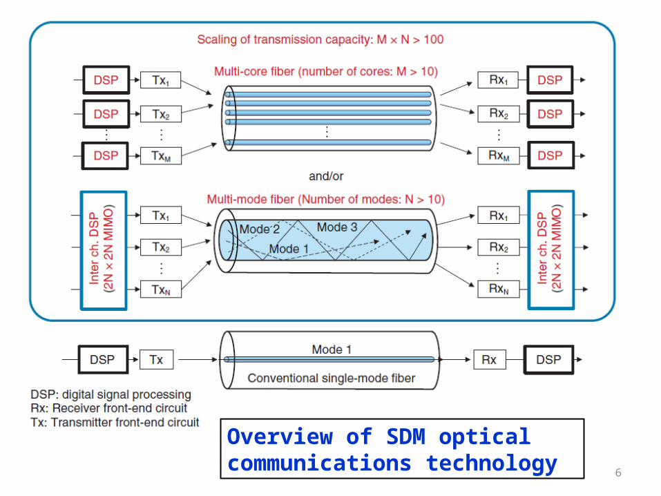
Overview of SDM optical communications technology

7
State of SDM research and development

8
Study toward dense SDM optical communications

Copyright © 2013 Nokia Siemens Networks

A brief history of Optical CommunicationThe original optical format used on-off-keying (OOK), with bits indicated by “light on” and “light off” states.
• The introduction of differential binary phase shift keying (DPSK) increased the receiver sensitivity and as such allowed for higher data rates, whereas differential quadrature phase shift keying (DQPSK) doubled the spectral effficiency.
• Capacity was then increased by increasing the bandwidth, but higher bandwidth is more vulnerable to distortion, so there are limits on how far this approach can go.
• Spectral efficiency was doubled yet again by transmitting and receiving information in two orthogonal polarizations.
• The arrival of coherent technology solved many underlying issues. Nokia Siemens Networks releasedits coherent transponder technology for 40 Gb/s in 2009. This was followed by 100 Gb/s in 2011.

Coherent technology blends optics and electronics, transforming the optical signal to the electrical domain by mixing it with a reference of the carrier frequency. This enables data to pass between the two domains complete with amplitude, polarization and phase information, which was not previously possible. Today’s coherent systems typically use a so-called 50 GHz grid. They have a reach in excess of 2,500 km depending on fiber type and system configuration.
Coherent detection with digital signal processing (DSP) improves receiver sensitivity, spectral efficiency and impairment compensation to increase the robustness and performance of the system, as shown in Table 1. Finally, the transmitter and receiver structures remain the same regardless of the modulation format. This makes it possible to deploy flexible rate transponders that use varying modulation formats depending on the given reach in the system.

The Limits of Single-Mode FibersOn a standard single-mode fiber with conventional optical amplifiers, higher order modulation formats cannot reach 2,000 km because of the required high optical signal-to-noise ratio.
• New, ultra-low-loss fibers with a high effective area and Raman amplification will be needed to overcome the 2,000 km limit with data rates of 400 Gb/s or more.
• Employing FlexiGrid, the improvements in spectral efficiency over standard single-mode fiber will only achieve a 20% boost in capacity, leading to a significant shortfall.

Ways to modulate and multiplex channels to increase system capacity in optical transmission.

Multi-Core and Multi-Mode Fibers
Solid-core record breakerIn 2012, Nokia Siemens Networks demonstrated a record capacity of 57.6 Tb/s transmitted over multi-mode fibers. This is six times the capacity of current 100 Gb/s systems and more than doubled the previous record over multi-mode fiber. The demonstration featured 200 Gb/s DP-16QAM per mode and wavelength transmitted over three spatial modes and 96 channels in the extended C-band. The transmission distance was 119 km with inline multi-mode amplification.
Hollow Core Record Breaker
Nokia Siemens Networks demonstrated record-breaking single mode capacity over hollow-core fiber in the first ever demonstration of coherent technology over this fiber type. The experiment achieved a capacity of 24 Tb/s. The researchers used single-mode transmission of 96 wavelength channels carrying dual polarization 32QAM modulation.


NATURE PHOTONICS | VOL 8 | MAY 2014 | www.nature.com/naturephotonics
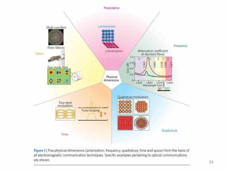
Five physical dimensions can be employed to carry optical data (Fig. 1): time, frequency, space, polarization and quadrature. These dimensions can be simultaneously used to greatly increase the bit rate of a communication system.
To avoid a ‘capacity crunch’, future optical networks will need to simultaneously transmit multiple spatial channels. For spatial multiplexing to be practical, the upgrade path from legacy wavelength-division multiplexed systems needs to be smooth and to consider integration-induced crosstalk from the outset.

Compatibility: As long as parallel fibre strands are available within a deployed cable, operators will want to make use of those, based on existing and deployed wavelength bands for which mature components are available. Hence, hybrid network architectures that use parallel fibre strands on some spans and possibly new SDM-specific fibre on other spans must be supported (see Fig. 2). A transition to new wavelength bands seems unlikely unless it results in a substantial (orders of magnitude) increase in system capacity and/or repeater spacing.
Integration: To follow historic trends and reduce cost and energy consumption per transmitted bit by about 20% per year, integration and unification of equipment in parallel WDM systems is essential. As shown in Fig. 2, integration may take place on a systems level (including network management and control), on a network element level (including reconfigurable optical add/drop multiplexers (ROADMs)), on a transponder level (similar to what is currently being done for spectral superchannel interfaces, where multiple signals at adjacent wavelengths are cohesively bonded to form a single architectural entity), on an optical amplifier level, and on a fibre and splice/ connection level to reduce installation costs.
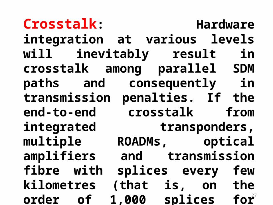
Crosstalk: Hardware integration at various levels will inevitably result in crosstalk among parallel SDM paths and consequently in transmission penalties. If the end-to-end crosstalk from integrated transponders, multiple ROADMs, optical amplifiers and transmission fibre with splices every few kilometres (that is, on the order of 1,000 splices for long-haul
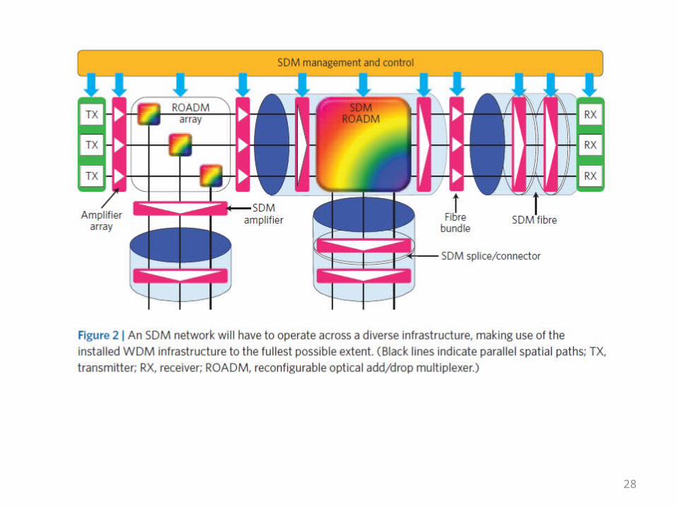
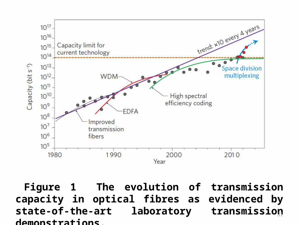
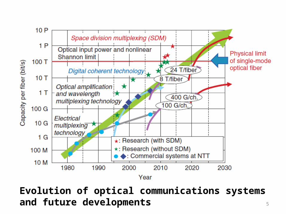
Figure 1 The evolution of transmission capacity in optical fibres as evidenced by state-of-the-art laboratory transmission demonstrations.

Figure 1 The evolution of transmission capacity in optical fibres as evidenced by state-of-the-art laboratory transmission demonstrations. The data points represent the highest capacity transmission numbers (all transmission distances considered) reported at the post deadline sessions of the annual Optical Fiber Communications Conference over the period 1982 to the present. The transmission capacity of a single fibre increases by a factor of approximately 10 every four years. Key previous technological breakthroughs include the development of low-loss SMFs, the EDFA, WDM and high-spectral-efficiency coding through DSP-enabled coherent transmission. The data points for SDM also include results from the postdeadline session of the annual European Conference on Optical Communications in 2011 and 2012. SDM seems poised to provide the next big jump in transmission capacity.
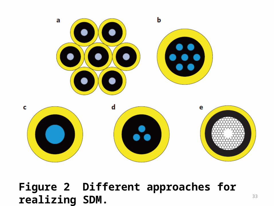
Figure 2 Different approaches for realizing SDM.
Figure 2 Different approaches for realizing SDM.a- Fibre bundles composed of physically independent SMFs with reduced cladding thickness could provide increased core packing densities relative to current fibre cables. However, ‘in-fibre’ SDM is required to achieve the higher core densities and integration levels ultimately desired.
b- MCF containing multiple independent cores with sufficiently large spacing to limit crosstalk. Fibres with up to 19 cores have been demonstrated for long-haul transmission — higher core counts are possible for short-haul applications (for example, data communications) for which higher levels of crosstalk per unit length can be tolerated.

35
c- FMF with a core dimension/numerical aperture set to guide a restricted number of modes (typically 6–12 distinct modes, including all degeneracies and polarizations).
d- Coupled-core fibres support supermodes that allow higher spatial mode densities than isolated-core fibres. MIMO processing is essential to address the inherent mode coupling.
e- Photonic bandgap fibres guide light in an air core and thus offer ultralow optical nonlinearity and potentially lower losses than solid-core fibres. Work is currently being conducted to determine whether such fibres can support MD

Figure 3 The many components needed to fully exploit the advantages of high-density SDM. a, Elegantly scalable passive multiplexers.
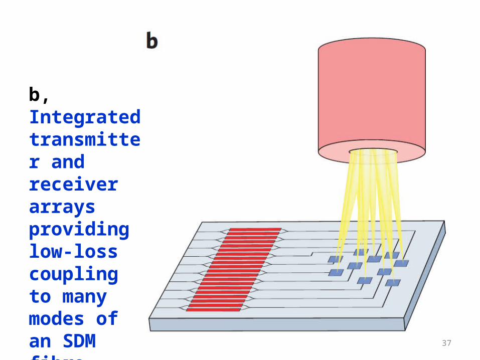
b, Integrated transmitter and receiver arrays providing low-loss coupling to many modes of an SDM fibre.
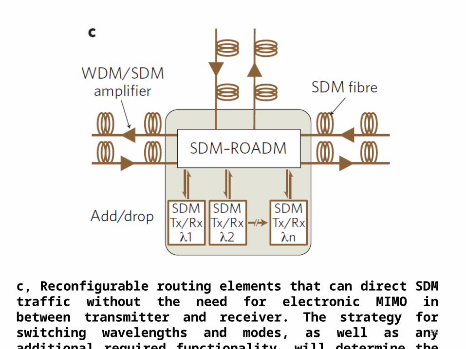
c, Reconfigurable routing elements that can direct SDM traffic without the need for electronic MIMO in between transmitter and receiver. The strategy for switching wavelengths and modes, as well as any additional required functionality, will determine the complexity of the ROADM architecture.

Table1 Summary of progress in SDM system experiments. Upper rows (shaded in purple) show experiments utilizing multicore fibres (MCF). Center row (shaded blue) shows a MCF-FMF result. Lower rows (shaded in pink) show transmission results over fewmode fibres (FMF). The channel rate includes polarization multiplexing; the Net Spectral Efficiency and Net Total Capacity exclude the overhead for forward-error-correction. SM: single-mode, FM: few-mode, coupled MCF: coupled-core MCF, mstr-MCF: microstructured, coupled-core MCF. The majority of SDM transmission experiments have utilized either 7-core MCF or FMF supporting 3 spatial modes. The table shows the rapid progress in both reach and net capacity achieved in just two years. Recent experiments utilizing a 12-core MCF and a MCF with hybrid SM and FM cores have demonstrated record net capacities of more than 1 Pb/s.
Progress in Systems Demonstration


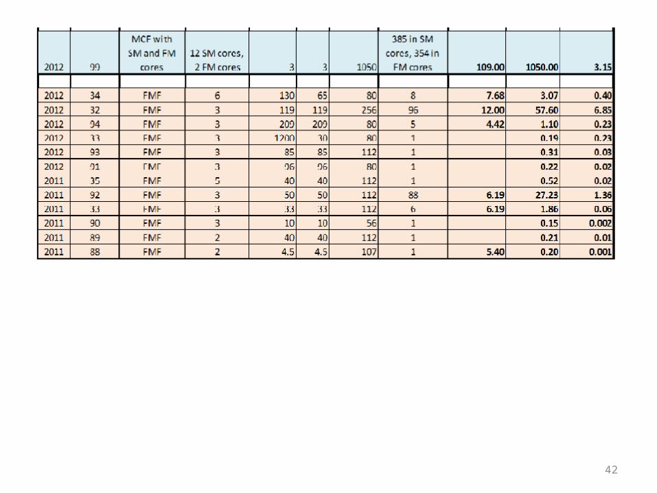
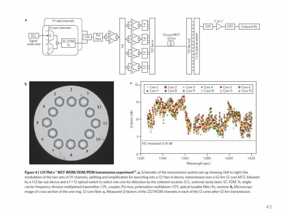
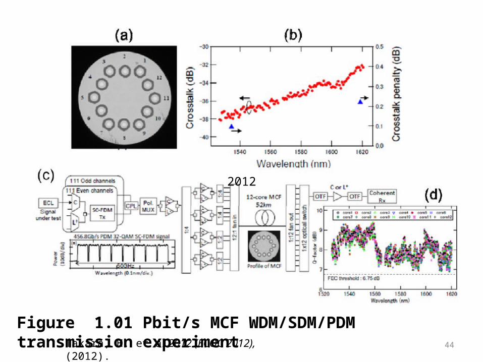
Figure 1.01 Pbit/s MCF WDM/SDM/PDM transmission experiment
2012
Takara, H. et al2012 (ECOC 2012), (2012).

(a) Microscope image of the cross section of the onering,12-core fibre. (b) Total crosstalk from all other cores after transmission over the 52km 12-core MCF and fan-in/fan-out devices (filled circles), and crosstalk penalty measured for two channels (filled triangles).
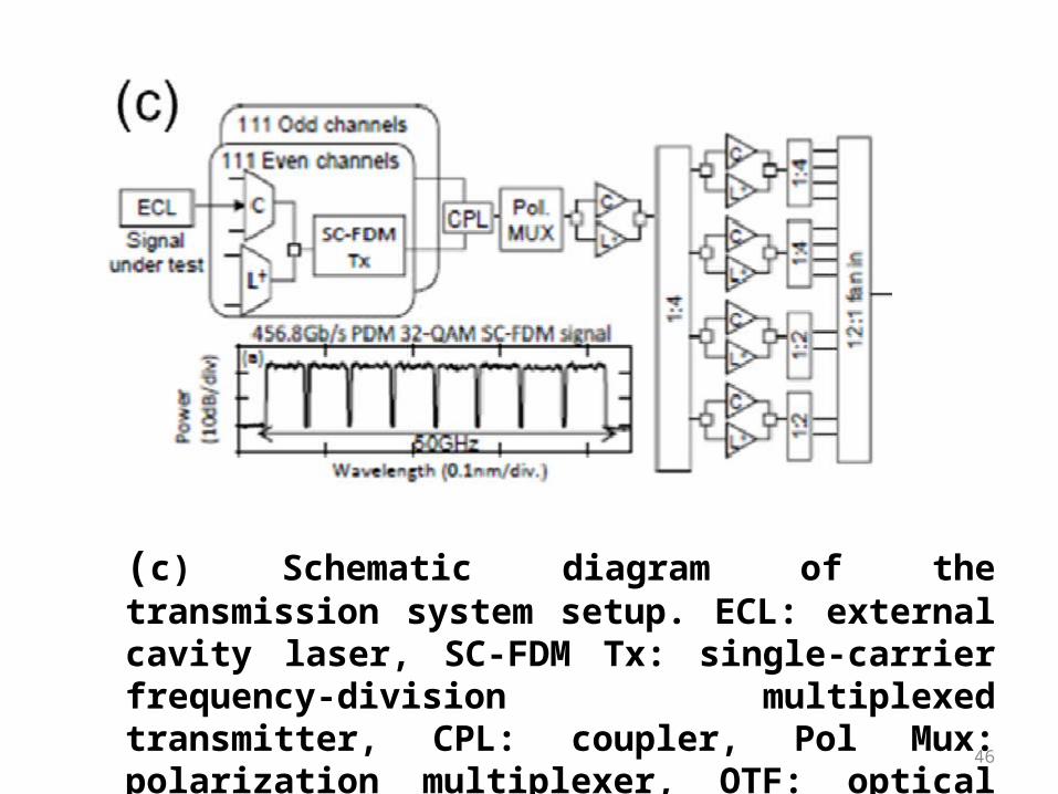
(c) Schematic diagram of the transmission system setup. ECL: external cavity laser, SC-FDM Tx: single-carrier frequency-division multiplexed transmitter, CPL: coupler, Pol Mux: polarization multiplexer, OTF: optical tunable filter, Rx: receiver
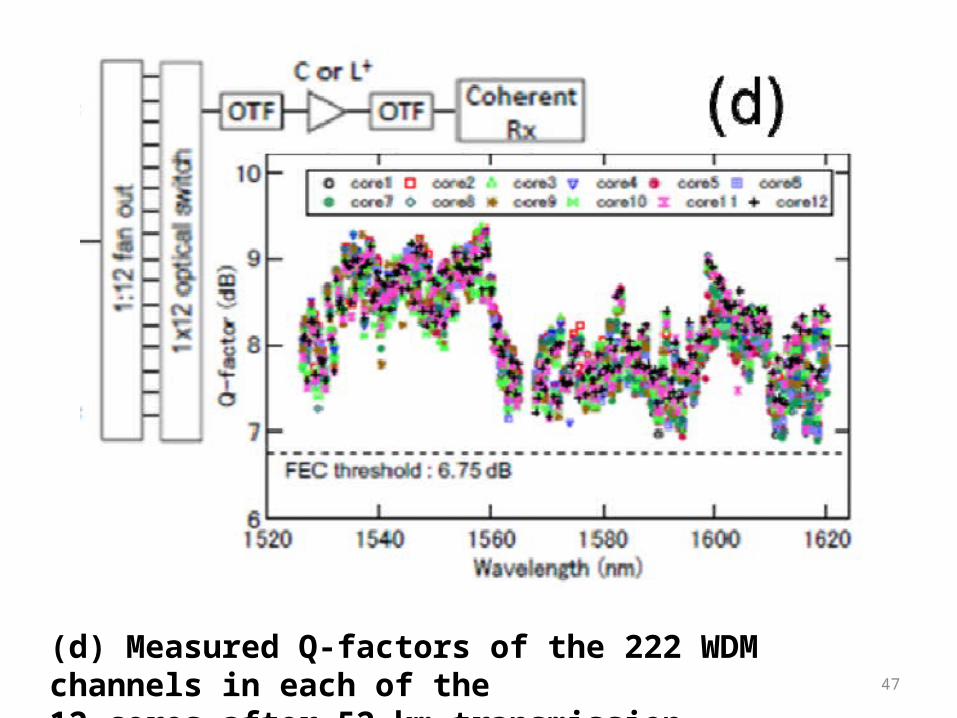
(d) Measured Q-factors of the 222 WDM channels in each of the12 cores after 52-km transmission.

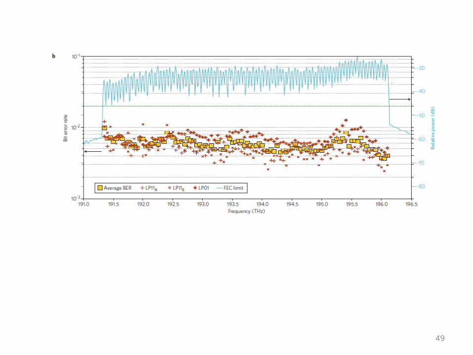
Figure 5 | 57.7 Tbit s−1 amplified WDM/MDM/PDM transmission experiment over a few-mode fibre34,102. a, Schematic of the experimental set-up showing (left to right) the three sets of transmitters for odd and even channels and the channel under test (CUT), splitting and amplification for launch into the mode multiplexer, transmission over the two few-mode-fibre spans with in-line MM-EDFA and mode demultiplexer and simultaneous reception of the channels transmitted in the three modes for MIMO processing. AWG, arrayed waveguide grating multiplexer; DAC, digital-to-analog converter; WSS, wavelength-selective switch; LO, local oscillator. b, Measured bit-error rates (markers) of all 96 channels in each of the three modes and optical spectrum (blue curve) after transmission over the 119 km of few-mode-fibre with a mid-span amplifier. BER, bit error rate; FEC, forward error correction.
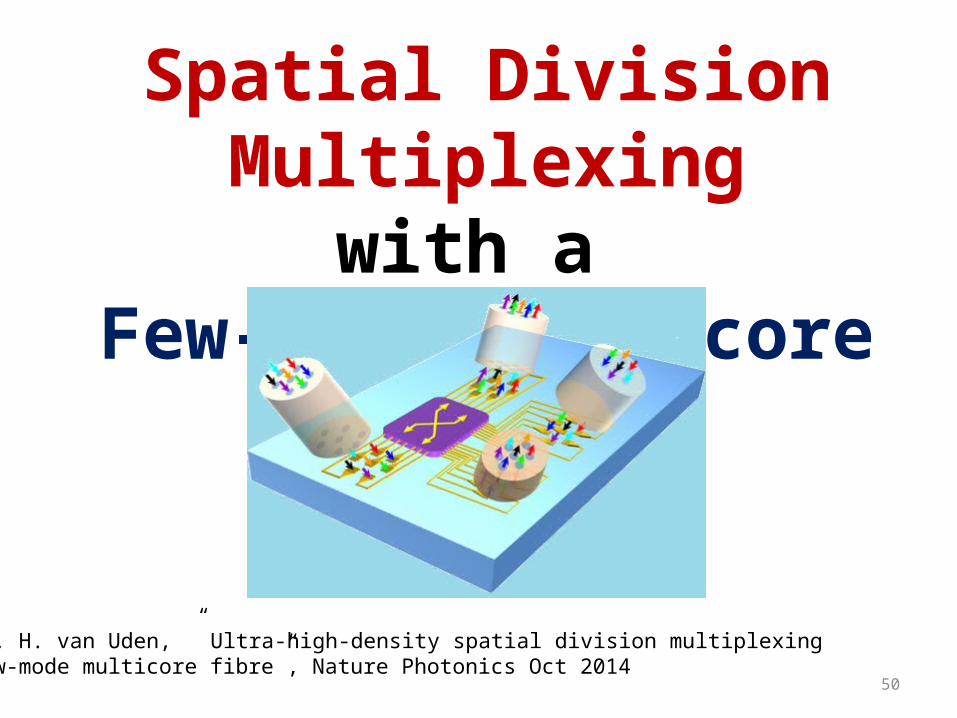
Spatial Division Multiplexingwith a
Few-Mode Multicore Fibre
Ref: R. G. H. van Uden, ” Ultra-high-density spatial division multiplexingwith a few-mode multicore fibre”, Nature Photonics Oct 2014
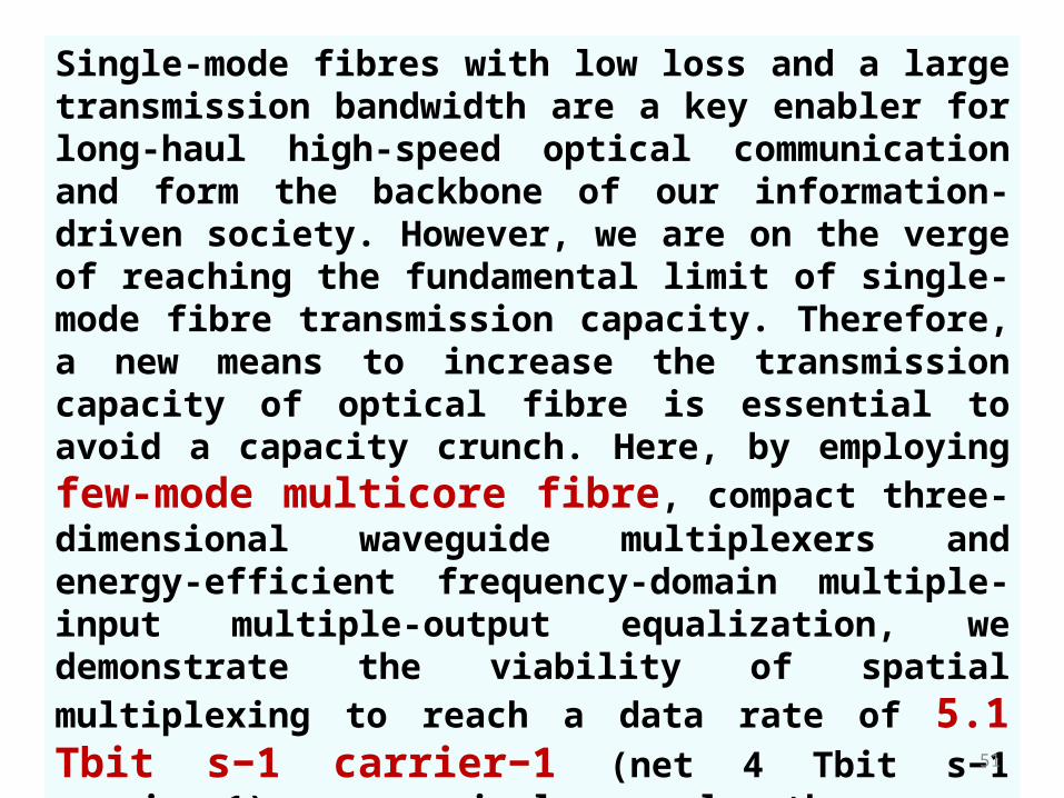
Single-mode fibres with low loss and a large transmission bandwidth are a key enabler for long-haul high-speed optical communication and form the backbone of our information-driven society. However, we are on the verge of reaching the fundamental limit of single-mode fibre transmission capacity. Therefore, a new means to increase the transmission capacity of optical fibre is essential to avoid a capacity crunch. Here, by employing few-mode multicore fibre, compact three-dimensional waveguide multiplexers and energy-efficient frequency-domain multiple-input multiple-output equalization, we demonstrate the viability of spatial multiplexing to reach a data rate of 5.1 Tbit s−1 carrier−1 (net 4 Tbit s−1 carrier−1) on a single wavelength over a single fibre. Furthermore, by combining this approach with wavelength division multiplexing with 50 wavelength carriers on a dense 50 GHz grid, a gross transmission throughput of 255 Tbit s−1 (net 200 Tbit s−1) over a 1 km fibre link is achieved.
Single-mode fibre transmission, is rapidly approaching its fundamental capacity limits
In the past, capacity increases in SMF transmission systems have been achieved by exploiting various dimensions, including polarization and wavelength division multiplexing, in tandem with advanced modulation formats and coherent transmission techniquesTo alleviate the corresponding costs and increased energy requirements associated with the linear capacity scaling from using additional SMFs, spatial division multiplexing (SDM) within a single fibre can provide a solution.

SDM is achieved through multiple-input multiple-output (MIMO) transmission, employing the spatial modes of a multimode fibre (MMF), or multiple single-mode cores, as channels. Recently, a distinct type of MMF, the few-mode fibre (FMF), has been developed to co-propagate three or six linear polarized (LP) modes. Driven by rapid enhancements in high-speed electronics, digital signal processing (DSP) MIMO techniques can faithfully recover mixed transmission channels, allowing spectral efficiency increases as spatial channels occupy the same wavelength.

In this work, ultra-high-capacity transmission over a 1 km is demonstrated using

Hole-Assisted Few-Mode Multicore Fibre

Figure 1 | Few-mode multicore fibre characteristics. a, FM-MCF cross-section, which is butt-coupled to the 3D waveguide.
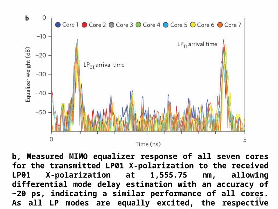
b, Measured MIMO equalizer response of all seven cores for the transmitted LP01 X-polarization to the received LP01 X-polarization at 1,555.75 nm, allowing differential mode delay estimation with an accuracy of 20 ps, indicating a ∼similar performance of all cores. As all LP modes are equally excited, the respective MIMO equalizer matrix elements are similar.
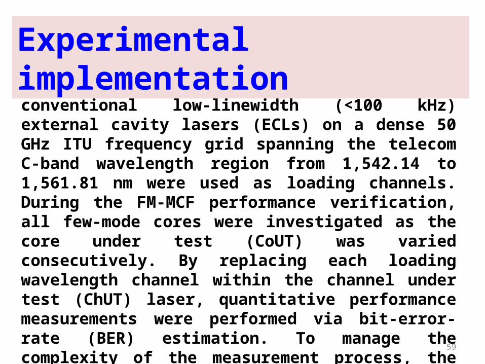
At the transmitter side (Fig. 2a), 50 conventional low-linewidth (<100 kHz) external cavity lasers (ECLs) on a dense 50 GHz ITU frequency grid spanning the telecom C-band wavelength region from 1,542.14 to 1,561.81 nm were used as loading channels. During the FM-MCF performance verification, all few-mode cores were investigated as the core under test (CoUT) was varied consecutively. By replacing each loading wavelength channel within the channel under test (ChUT) laser, quantitative performance measurements were performed via bit-error-rate (BER) estimation. To manage the complexity of the measurement process, the transmitter ChUT laser was split into two equal tributaries, with the second tributary acting as a remote local oscillator (LO) for all 700 measurements.
Experimental implementation

As the transmitter and receiver shared the same laser source, a 10 km SMF was inserted into the LO path to minimize the impact of laser phase coherence. All carriers were modulated by a lithium niobate (LiNbO3) IQ-modulator, which was driven by two digital-to-analog converters (DACs), representing the in-phase and quadrature components, to generate a 24.3 GBaud 16 or 32 QAM signal. Higher-order modulation formats are particularly interesting for fibre performance investigation because of their susceptibility to impairments in the transmission channel. Before transmission, the modulated carriers were decorrelated consecutively for polarization, carriers, modes and cores. The relative powers of the decorrelated carriers are shown in Fig. 2b, showing a relatively equal power distribution over the entire transmitted wavelength band.
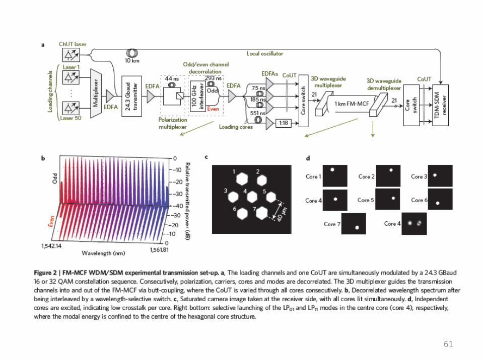

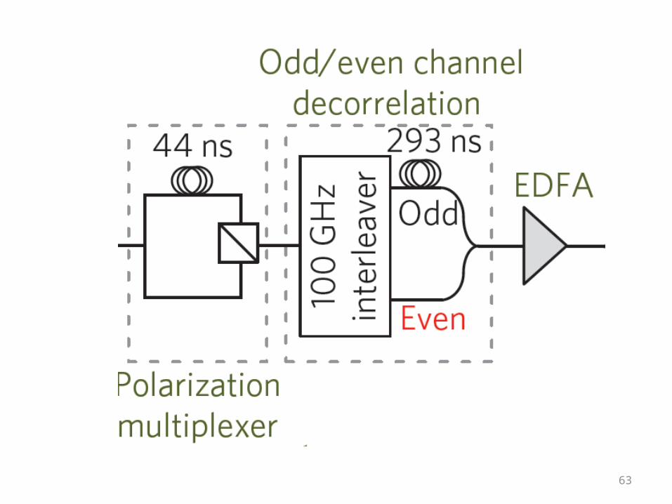


Decorrelated wavelength spectrum after being interleaved by a wavelength-selective switch.

Saturated camera image taken at the receiver side, with all cores lit simultaneously

Independent cores are excited, indicating low crosstalk per core. Right bottom: selective launching of the LP01 and LP11 modes in the centre core (core 4), respectively, where the modal energy is confined to the centre of the hexagonal core structure.

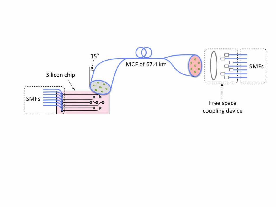
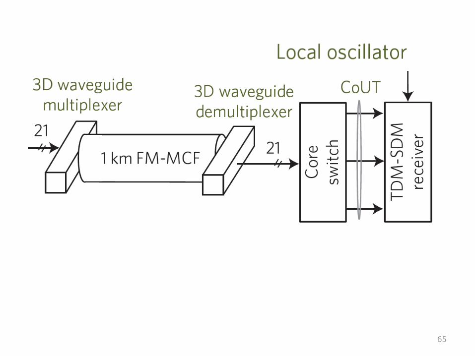
The 21 SMF inputs (with a 127 μm pitch V-groove) were attached to waveguides (assigned in seven sets of three waveguides) and inscribed in a hexagonal arrangement with a diameter of 80 μm to match the core arrangement and structure of the FM-MCF (Fig. 3a). The individual square waveguides have a cross-sectional effective area of 36 μm2 (Fig. 3b), and each set of three waveguides was placed in a triangular arrangement38. This arrangement minimizes insertion losses, while equally exciting the LP01 and LP11 degenerate modes in each core to minimize mode-dependent loss (MDL). The MDL was approximated at 1.5–2 dB and the insertion loss on average was 1.1 dB across all 21 waveguides (excluding fibre) at 1,550 nm. The total end-to-end loss measured after transmission was 12 dB (including multiplexer and demultiplexer 3D waveguide), which is in line with single-core few-mode results34. Crosstalk was measured by individually exciting the different cores. The measured crosstalk value was below −70 dB km−1.
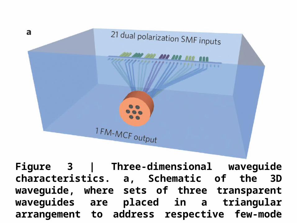
Figure 3 | Three-dimensional waveguide characteristics. a, Schematic of the 3D waveguide, where sets of three transparent waveguides are placed in a triangular arrangement to address respective few-mode cores.
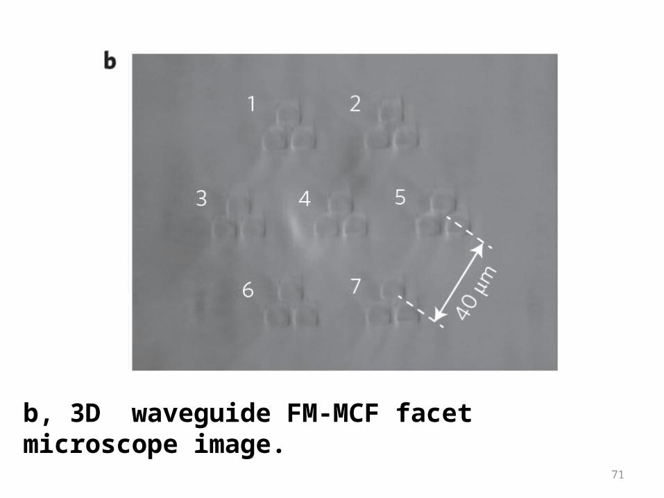
b, 3D waveguide FM-MCF facet microscope image.

To enable mode measurement after FM-MCF propagation, an elegant few-mode measurement technique is proposed and devised . The essence of the technique is shown in Fig. 4a, where the novel time-domain multiplexed (TDM) SDM receiver with two dual-polarization coherent receivers is used for simultaneous reception of the three transmitted
modes per core. The first coherent receiver receives the first mode and a second coherent receiver receives the remaining two modes, demonstrating the potential scaling of received modes in both time and number of dualpolarization coherent receivers.

Figure 4 | TDM-SDM receiver characterization. a, TDM-SDM receiver, where one dual polarization mode is received by coherent receiver 1 and two modes are serially received by coherent receiver 2. The AOMs act as signal gates, with a closing time corresponding to the propagation time of the delay fibre, enabled by the trigger generator. The variable optical attenuator (VOA) ensures equal power reception of both modes. In the digital domain, the serialized signals are parallelized to construct three received dual-polarization modes.
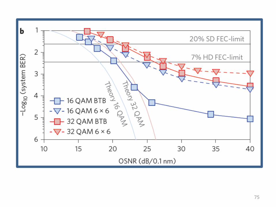
To demonstrate the FM-MCF transmission capabilities, first the transmitter and receiver performance is characterized by noise loading at the transmitter side for optical signal-to-noise ratio (OSNR) measurements as depicted in Fig. 4b. At the 40 dB OSNR level, with respect to back-to-back measurements, the 6 × 6 single channel MIMO measurements for 16 and 32 QAM indicate a modest error floor increase of 2 × 10⁻⁴ and 8 × 10⁻⁴ for single wavelength transmission, respectively. This BER increase is mainly attributed to residual channel interference after the frequency domain MIMO equalizer unravels the channels.
Results
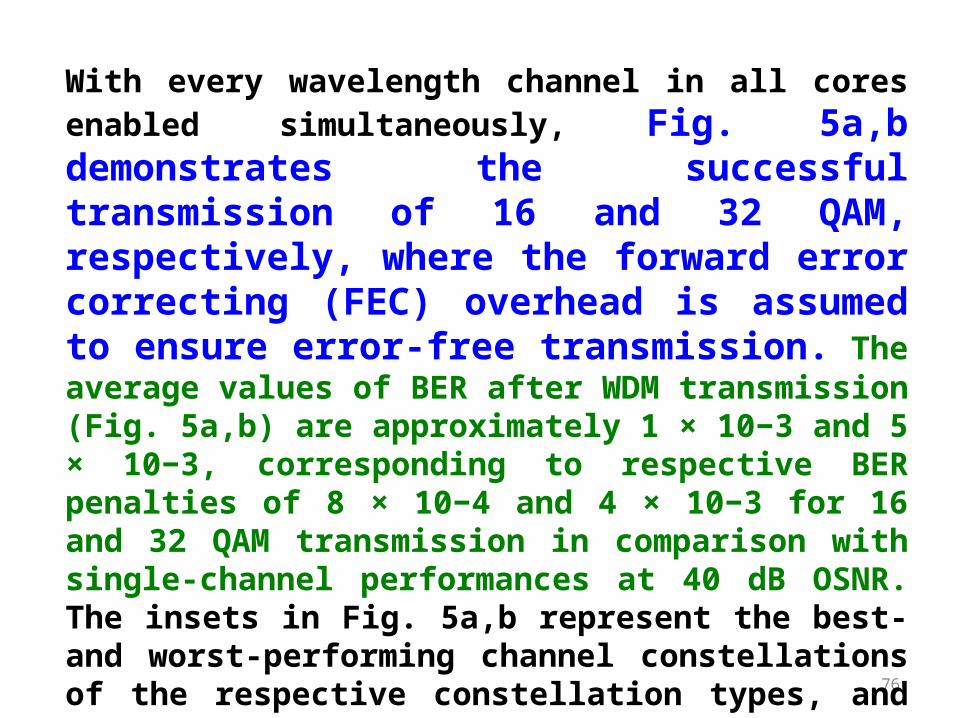
With every wavelength channel in all cores enabled simultaneously, Fig. 5a,b demonstrates the successful transmission of 16 and 32 QAM, respectively, where the forward error correcting (FEC) overhead is assumed to ensure error-free transmission. The average values of BER after WDM transmission (Fig. 5a,b) are approximately 1 × 10⁻³ and 5 × 10⁻³, corresponding to respective BER penalties of 8 × 10⁻⁴ and 4 × 10⁻³ for 16 and 32 QAM transmission in comparison with single-channel performances at 40 dB OSNR. The insets in Fig. 5a,b represent the best- and worst-performing channel constellations of the respective constellation types, and the gross aggregate transmission capacity of 255.15 Tbit s−1 signifies the potential high-density space-division-multiplexing capabilities of the hole-assisted FM-MCF.

Figure 5 | Transmission results. a, 16 QAM transmission performance. All channels perform well below the 7% hard decision FEC limit required to ensure error-free transmission for a 81.6 bit s−1 Hz−1 gross spectral efficiency.
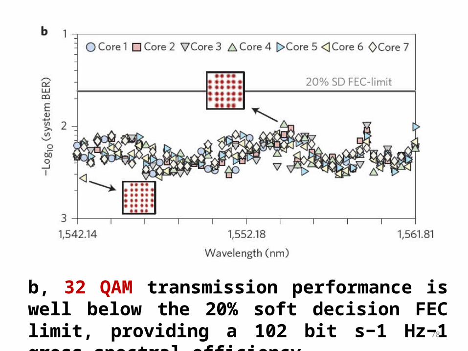
b, 32 QAM transmission performance is well below the 20% soft decision FEC limit, providing a 102 bit s−1 Hz−1 gross spectral efficiency
However, inherent to space-division-multiplexed transmission is a received power difference between transmitted channels, denoted by the MDL. Obtained from mutual information estimation, MDL is a figure of merit for establishing the theoretical transmission capacity, which is computed through singular value decomposition of the transmission channel matrix, obtained by least squares channel estimation. The MDL figures of all wavelength carriers are presented in Fig. 5c,d, with average estimated MDLs of 3.9 dB and 4.4 dB for 16 and 32 QAM, respectively. The small MDL differences are attributed to slight misalignment between the cores and (de)multiplexer, as well as wavelength-dependent mode field excitation during the experiment.
Mode-dependent loss (MDL)

c, 16 QAM transmission measured MDL figures for all transmitted channels, averaging at 3.9 dB.