Embed Size (px)
Citation preview

Research ArticleNumerical Simulation of Creep Damage and Life Prediction ofSuperalloy Turbine Blade
Donghuan Liu,1 Haisheng Li,2 and Yinghua Liu3
1Department of Applied Mechanics, University of Science and Technology Beijing, Beijing 100083, China2National Center for Materials Service Safety, University of Science and Technology Beijing, Beijing 100083, China3School of Aerospace, Tsinghua University, Beijing 100084, China
Correspondence should be addressed to Yinghua Liu; [email protected]
Received 13 September 2014; Accepted 2 December 2014
Academic Editor: Chenfeng Li
Copyright © 2015 Donghuan Liu et al. This is an open access article distributed under the Creative Commons Attribution License,which permits unrestricted use, distribution, and reproduction in any medium, provided the original work is properly cited.
Creep caused failure is an important failure mode of the turbine blade. A numerical approach of life assessment of the superalloyturbine blade is proposed in the present paper based on the Lemaitre-Chaboche creep damagemodel.Material damage is introducedinto each element based on the ANSYS APDL function, and the creep damage effect is considered through the modificationof Young’s modulus. At last, the strength life and stiffness life of the blade can be obtained through the maximum damage andmaximum creep strain criterion, respectively. The present method can not only consider the effect of creep damage, but also givethe time histories of the element stresses, damage, and creep strain.The above life prediction results based on the proposedmethodare compared with the 𝜃 projection method, and the results suggest that the present life prediction method of turbine blade isfeasible and turbine blade’s life in the present study is determined by creep fracture rather than creep deformation.
1. Introduction
Creep failure is one of the most important failure modesof turbine blade. Creep is the progressive time-dependentinelastic deformation under mechanical load and high tem-perature. The creep process is accompanied by many dif-ferent microstructural rearrangements including dislocationmovement, aging of microstructure, and grain-boundarycavitation. Over the preceding decades, many numericaland experimental investigations have been performed toimprove the knowledge of creep of structures under hightemperature. Creep constitutive relationship, creep damageevolution equation, and creep life prediction method arethree main topics.
Hayhurst et al. presented a methodology for accuratelycalibrating constitutive parameters for a 1/2Cr–1/2Mo–1/4Vferritic steel. The accurate description achieved is attributedto the physical basis of the constitutive equations and par-ticularly to the state variables that represents the coarseningof the carbide precipitates and the creep constrained cavitygrowth [1, 2]. Hore and Ghosh developed a simple method
of estimating material parameters for Dyson-McLean model[3]. Constitutive equations for time independent plasticityand creep of 316 stainless steel at 550∘C were given by Hay-hurst et al. [4]. Ma et al. presented a method for determiningthe power law creep constants using the small punch (SP)creep test [5]. The biggest advantage of SP creep test isthat it can be used to evaluate remaining creep life usingvery small specimens extracted from in-service components.Saad et al. developed amaterial constitutivemodel for the P91and the P92 steels under cyclic loading and high tempera-ture conditions [6]. Bolton proposed a characteristic-strainmodel of creep of analyzing long term-relaxed stresses andcreep strains in engineering components under steady load[7]. Bolton independently examined the worked examplepresented in BSI document PD6605-1:1998, to illustrate theselection, validation, and extrapolation of a creep rupturemodel using statistical analysis [8]. Wilshire and Scharningpresented a new approach to analysis of stress rupture dataallowing rationalization, extrapolation, and interpretation ofmultibatch creep life measurements reported for ferritic 1Cr–0.5Mo tube steel [9]. Holdsworth et al. reviewed results are
Hindawi Publishing CorporationMathematical Problems in EngineeringVolume 2015, Article ID 732502, 10 pageshttp://dx.doi.org/10.1155/2015/732502

2 Mathematical Problems in Engineering
of an ECCC work program to investigate procedures for thepractical representation of mean creep behavior for well-specified alloys from large multisource, multicast strain-timedatasets. Leinster proposed a method of creep rupture dataextrapolation based on physical processes [10].
Zhang et al. studied creep-fatigue interaction damageevolution of the nuclear engineeringmaterials modified 9Cr–1Mo steel with continuum damage mechanics (CDM) theory[11]. Wilshire and Burt interpreted normal creep curves interms of the deformation mechanisms controlling strainaccumulation and the damage processes causing tertiaryacceleration and eventual failure [12]. Hyde et al. usedsingle-state variable and three-state variable creep damageconstitutive models to investigate the material behavior oftwo P91 steels of differing strength [13]. Spindler determinedthe material properties of some creep and constant strainrate tests on a Type 347 weld metal, and then various creepdamage models are used to predict the creep damage in somecreep-fatigue tests on the same Type 347 weld metal [14, 15].Guan et al. presented quantitative study of creep cavity areaof HP40 furnace tubes [16]. Hyde et al. presented a novelmodelling process for creep crack growth prediction of a316 stainless steel using continuum damage mechanics, inconjunctionwith finite element (FE) analysis [17]. Smith et al.investigated the type IV creep cavity accumulation and failurein steel welds [18].
Mackerle reviewed the finite element methods appliedto creep and creep fracture/damage of engineering materialsand structures from the theoretical as well as practical pointsof view [19]. Masuyama interrupted large-size cross-weldcreep rupture testing at given creep life fractions until ruptureto measure the hardness, microstructure, and potential dropin the heat affected zones of welds to clarify creep degradationin welds of Mod.9Cr-1Mo steel [20]. Ling et al. performedseveral small punch creep tests on Type 304 stainless steel at650∘C and presented a finite element model with modifiedKachanov-Rabotnov creep damage constitutive equations[21]. Izaki et al. proposed a residual creep life assessmentmethod for boiler pipes using small punch creep (SPC) test[22]. Masse and Lejeail numerically investigated the creepbehaviour anddamagemechanisms ofmodified 9Cr1Mo steelbetween 450∘C and 650∘C [23, 24]. Weber et al. developed amethod for creep life prediction for pipe bends withGraham-Wallas creep law [25]. Oldham and Abou-Hanna presented afast and effective method for creep-fatigue life prediction of9Cr-1Mo (grade 91) for a temperature range of 500∘C−550∘C[26]. Oh et al. proposed a method to simulate creep failureusing finite element damage analysis and the method wasapplied to simulate creep crack growth in six different typesof cracked specimens of 316H at 550∘C. The creep damagemodel is based on the creep ductility exhaustion concept, andincremental damage is defined by the ratio of incrementalcreep strain and multiaxial creep ductility [27, 28]. Yao et al.grouped the existing theories and creep design approachesinto three categories, that is, the classical plastic theory (CPT)based approach, the cavity growth mechanism (CGM) basedapproach, and the continuum damage mechanics (CDM)based approach [29].
Beside these, many efforts are devoted to the life pre-diction of turbine blade. Lewis and Beckwith reviewedthe life prediction approaches of the turbine blade [30].Abu et al. provided a life assessment tool for aero jet engineblades by integrating suitable models and software with theNeu/Sehitoglu damage model [31]. Marahleh et al. predictedthe operating life of service-exposed blades used in industrialgas turbines [32]. Chen et al. proposed a power-exponentfunctionmodel for the life prediction of turbine blades undercreep-fatigue interaction [33, 34]. Rodrıguez et al. developedartificial neural network (ANN) to predict the useful life(UL) of the blades [35]. Schonbauer et al. investigated theinfluence of corrosion pits on the endurable fatigue loadingin different environments and at various stress ratios for 12%Cr steam turbine blade steel [36]. Tawancy and Al-Hadhramicompared the microstructural changes of unused and usedblades in power generation [37].
Although many researches have conducted on the creepperformance of the turbine blade, previous works alwaysperform the finite element calculation through complex creepand damage relations with user subroutine. In the presentresearch, a simple and feasible approach is proposed toinvestigate the creep life of turbine blade.
2. Material Characterization
This section gives the thermophysical parameters, creepconstitutions, and creep damage evolution relationship of theturbine blade material GH4169. GH4169 is a domestic hightemperature alloy, known as Inconel 718 in USA.
Thermal and mechanical properties such as thermalconductivity, specific heat, elastic modulus, Poisson’s ratio,and thermal expansion coefficient are presented in Tables 1, 2,3, 4, and 5 [38].These parameters are temperature-dependent.Density of GH4169 is 8240 kg/m3 and is assumed to be aconstant.
The most important and widely used constitutive equa-tion to predict the secondary creep is Norton’s power lawequation:
𝜀cr = 𝐶1𝜎𝐶2e−𝐶3/𝑇, (1)
where 𝜀cr is the steady state creep strain rate, 𝜎 is stress (MPa),𝑇 is temperature (K), 𝐶
1, 𝐶2, and 𝐶
3are material constant
which should be determined based on creep test data, andthey are 𝐶
1= 2.147 × 10
−70.03, 𝐶2= 10.171, and 𝐶
3=
50825.890, respectively [39].Creep caused damage is also considered in the present
research, and the damage evolution relationship is given bythe modified Lemaitre-Chaboche model [40]:
𝑑𝐷𝐶
𝑑𝑡= (
𝜎
𝐴)
𝑟
(1 − 𝐷𝐶)−𝑘
, (2)
where𝐷𝐶is the creep damage, 𝑡 is time (h), 𝜎 is stress (MPa),
and 𝑘 is given by
𝑘 = 𝑎0+ 𝑎1(𝜎 − 𝑧) + 𝑎
2(𝜎 − 𝑧)
2
, (3)
where 𝑟, 𝐴, 𝑎0, 𝑎1, 𝑎2, and 𝑧 are material constant which
should be determined based on creep test data and are shownin Table 6 [41].
Mathematical Problems in Engineering 3
Table 1: Thermal conductivity of GH4169 with different temperatures.
T/∘C 100 200 300 400 500 600 700 800 900 1000𝜆/(W/(m⋅∘C)) 14.7 15.9 17.8 18.3 19.6 21.2 22.8 23.6 27.6 30.4
Table 2: Specific heat of GH4169 with different temperatures.
T/∘C 300 400 500 600 700 800 900 1000C/(J/(kg⋅∘C)) 481.4 493.9 514.8 539 573.4 615.3 657.2 707.4
Table 3: Elastic modulus of GH4169 with different temperatures.
𝑇/∘C 25 400 500 650 750𝐸/GPa 205 175.5 168.5 142 130.5
Table 4: Poisson’s ratio of GH4169 with different temperatures.
𝑇/∘C 25 300 400 500 600 650 750𝜇 0.321 0.329 0.339 0.344 0.355 0.361 0.381
It should be noted that as (2) is nonlinear, the computa-tion of the damage is an iterative process.
3. Thermomechanical Analysis
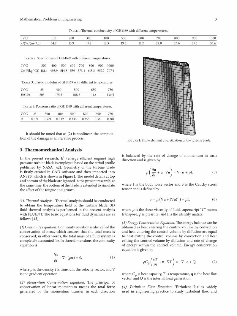
In the present research, 𝐸3 (energy efficient engine) highpressure turbine blade is employed based on the airfoil profilepublished by NASA [42]. Geometry of the turbine bladeis firstly created in CAD software and then imported intoANSYS, which is shown in Figure 1. The model details at topand bottomof the blade are ignored in the present research; atthe same time, the bottomof the blade is extended to simulatethe effect of the tongue and groove.
3.1. Thermal Analysis. Thermal analysis should be conductedto obtain the temperature field of the turbine blade. 3Dfluid thermal analysis is performed in the present analysiswith FLUENT. The basic equations for fluid dynamics are asfollows [43].
(1) Continuity Equation.Continuity equation is also called theconservation of mass, which ensures that the total mass isconserved; in other words, the total mass of a fluid system iscompletely accounted for. In three dimensions, the continuityequation is
𝜕𝜌
𝜕𝑡+ ∇ ⋅ (𝜌u) = 0, (4)
where 𝜌 is the density, 𝑡 is time, u is the velocity vector, and ∇is the gradient operator.
(2) Momentum Conservation Equation. The principal ofconservation of linear momentum means the total forcegenerated by the momentum transfer in each direction
Figure 1: Finite element discretization of the turbine blade.
is balanced by the rate of change of momentum in eachdirection and is given by
𝜌(𝜕u𝜕𝑡+ u ⋅ ∇u) = ∇ ⋅ 𝜎 + 𝜌f , (5)
where f is the body force vector and 𝜎 is the Cauchy stresstensor and is defined by
𝜎 = 𝜇 (∇u + (∇u)𝑇) − 𝑝I, (6)
where 𝜇 is the shear viscosity of fluid, superscript “𝑇” meanstranspose, 𝑝 is pressure, and I is the identity matrix.
(3) Energy Conservation Equation.The energy balance can beobtained as heat entering the control volume by convectionand heat entering the control volume by diffusion are equalto heat exiting the control volume by convection and heatexiting the control volume by diffusion and rate of changeof energy within the control volume. Energy conservationequation is given by
𝜌𝐶𝑝(𝜕𝑇
𝜕𝑡+ u ⋅ ∇𝑇) = −∇ ⋅ q + 𝑄, (7)
where 𝐶𝑝is heat capacity, 𝑇 is temperature, q is the heat flux
vector, and 𝑄 is the internal heat generation.
(4) Turbulent Flow Equation. Turbulent 𝑘-𝜀 is widelyused in engineering practice to study turbulent flow, and

4 Mathematical Problems in Engineering
Table 5: Thermal expansion coefficient of GH4169 with different temperatures.
𝑇/∘C 100 200 300 400 500 600 700 800 900 1000𝛼/(10−6∘C−1) 11.8 13.0 13.5 14.1 14.4 14.8 15.4 17 18.4 18.7
Table 6: Thermal expansion coefficient of GH4169 with differenttemperatures.
Parameter 𝑟 𝐴 𝑧 𝑎0
𝑎1
𝑎2
Value 13.19 1209 733.25 13.2478 0.7865 × 10⁻⁴ 0.1924 × 10⁻³
the turbulent kinetic 𝑘 equation and turbulent dissipation 𝜀equation are given, respectively, by
𝜕 (𝜌𝑘)
𝜕𝑡+ ∇ ⋅ (𝜌u𝑘) = ∇ ⋅ ((𝜇 + 𝜇𝑡
𝜎𝑘
)∇𝑘) − 𝜌𝜀 + 𝜇𝑡𝑃𝐺,
𝜕 (𝜌𝜀)
𝜕𝑡+ ∇ ⋅ (𝜌u𝜀) = ∇ ⋅ ((𝜇 + 𝜇𝑡
𝜎𝜀
)∇𝜀)
− 𝜌𝐶2
𝜀2
𝑘+ 𝜇𝑡𝐶1
𝜀
𝑘𝑃𝐺,
(8)
where turbulent viscosity coefficient 𝜇𝑡and turbulent kinetic
generation term 𝑃𝐺satisfied
𝜇𝑡= 𝜌𝐶𝜇
𝑘2
𝜀,
𝑃𝐺= 2 [(
𝜕𝑢
𝜕𝑥)
2
+ (𝜕V𝜕𝑦)
2
+ (𝜕𝑤
𝜕𝑧)
2
]
+ (𝜕𝑢
𝜕𝑦+𝜕V𝜕𝑥)
2
+ (𝜕𝑢
𝜕𝑧+𝜕𝑤
𝜕𝑥)
2
+ (𝜕V𝜕𝑧+𝜕𝑤
𝜕𝑦)
2
,
(9)
where 𝑘 is turbulent kinetic energy, 𝜀 is the turbulentdissipation rate, and 𝜇
𝑡, 𝜎𝑘, 𝜎𝜀, 𝐶1, 𝐶2, and 𝐶
𝜇are constant.
The fluid heat transfer analysis is conducted with FLU-ENT after importing the finite element model from ANSYS.
Convective heat transfer boundary is applied at the innersurface of the cooling channel of the turbine blade, and theconvective heat transfer coefficient and wall temperature areassumed to be 400W/m2K and 600K, respectively. The inletpressure is 1.324MPa and the inlet temperature is 1633 K.Temperature field of the turbine blade is given in Figure 2.
It can be seen from Figure 3 that the temperature isranging from 770K to 920K, and the maximal temperatureis about 920K at the bottom of the leading edge. In general,when temperature is larger than 0.3 times of the melt point,creepwill become important, and themelt point of GH4169 isabout 1533K, which means creep plays a very important rolein the life prediction of the turbine blade.
3.2. Mechanical Analysis. There are different sources of loadsimposed on the turbine blade. Due to the rotation, the blade is
Temperature (K)
920
910
900
890
880
870
860
850
840
830
820
810
800
790
780
Figure 2: Temperature field of the turbine blade.
Mises stress (MPa)
800
750
700
650
600
550
500
450
400
350
300
250
200
150
10050
Figure 3: Equivalent stress field of the turbine blade under inertialforce.

Mathematical Problems in Engineering 5
Mises stress (MPa)
140
130
120
110
100
90
80
70
60
50
40
30
20
10
Figure 4: Equivalent stress field of the turbine blade under temper-ature.
subjected to inertial forcewhich acts along the axial direction,and the angular velocity of the blade is 13223 rpm. Aero-dynamic pressure is not considered in the present research.Temperature field obtained in the previous section is appliedon the finite element node as body forces. The computationis conducted with ANSYS, and SOLID185 element withhexahedron mesh is used. There are 11026 meshes and 14630nodes. Three load cases are calculated; only inertial force,only temperature, both inertial force and temperature, andthe equivalent stress field of the turbine blade under thesethree conditions are shown in Figures 3, 4, and 5, respectively.
It can be seen from Figures 3–5 that, under individualinertial force and temperature, the maximal equivalent stressof the turbine blade is 800MPa and 140MPa respectively,while with the consideration of both inertial force andtemperature, the maximal equivalent stress is 850MPa. It isfound that inertial force is the primary source of the bladestress, and thermal stress is secondary. The main effect of thetemperature is that of activation of the creep process.
4. Creep Life Prediction
4.1. Computational Flowchart. Equations (1) and (2) areimplemented within ANSYS in the present research. Withthe development of the creep process, the stress is relaxedand becomes smaller, while creep damage becomes larger. Asdamage is affected by stress and temperature, which is quitedifferent from element to element, creep in each element isdifferent. In the present research, effect of damage to the bladeis realized by changing Young’s modulus of the material:
𝐸 = 𝐸0(1 − 𝐷
𝐶) , (10)
Mises stress (MPa)
850
800
750
700
650
600
550
500
450
400
350
300
250
200
150
10050
Figure 5: Equivalent stress field of the turbine blade under bothinertial force and temperature.
where𝐸 is present Young’smodulus and𝐸0is original Young’s
modulus. It is noted that even original Young’s modulus ofeach element is different as the temperature of each elementis different.
The computations are conducted by the following steps.
Step 1. Import CAD model of the turbine blade into ANSYS.
Step 2. Mesh the turbine blade and assign every element withdifferent material number.
Step 3. Import finite element model into FLUENT andperform the fluid heat transfer computation to obtain the heatflux field of the outer surface of the turbine blade.
Step 4. Import the heat flux field of the outer surface of theturbine blade obtained in Step 3 and apply boundary condi-tions at the surface of the cooling channel and then performthe heat transfer computation to obtain the temperature fieldof the turbine blade.
Step 5. Switch element type from thermal analysis to struc-tural analysis and apply node temperature obtained in Step 4as body force and structural boundary conditions and inertialforce. Initialize the damage of each element.
Step 6. Begin computation and give displacement, stress, andstrain.
Step 7. Compute element damage with (2).
Step 8. Evaluate the safety of the turbine blade with failurecriterion. If the turbine blade is failed, the present time will

6 Mathematical Problems in Engineering
Mises stress (MPa)
500
450
400
350
300
250
200
150
100
50
Figure 6: Equivalent stress of the turbine blade after creep 441 h.
be the lifetime of the turbine blade. If not, modify Young’smodulus of each element with element damage obtained inStep 7 and then turn to Step 6 to perform computation of thenext time step.
Two-creep failure criterion is considered in the presentresearch, one is creep rupture when the maximum damageof the structure reaches a threshold value, and the other iscreep deformation failure when the creep strain or creepdeformation reaches a threshold value. In the present paper,lifetime based on these two failure modes is called strengthlifetime and stiffness lifetime, respectively, since the gapbetween the rotor and stator is usually less than 1/1000 of therotational radius of the blade to prevent or reduce the gasleakage through the blade tip-gap.
Load and boundary conditions in creep analysis are thesame as in the mechanical analysis, and during the wholecomputation these conditions are assumed to be constant.
4.2. Strength Lifetime. In the present research, thresholdvalue of element damage is defined by 𝐷
𝐶= 0.4, as
the remaining creep time before complete failure occurs isvery small compared to the total creep time. Time whenthe maximal element damage reaches 0.4 is defined as thestrength lifetime of the turbine blade. It is found that thestrength lifetime of the turbine blade in the present researchis 441 h, with a maximal element damage of 0.415. After creepfor 441 h, the equivalent stress and element damage of theturbine blade are shown in Figures 6 and 7, respectively.Figures 8 and 9 give the evolution of the maximal elementdamage and maximal equivalent stress.
Compared with Figures 5 and 6, it can be found that aftercreep for 441 h, the maximal equivalent stress decreases from
Damage
1
0.1
0.01
0.001
0.0001
1E−05
1E−06
1E−07
1E−08
1E−09
1E−10
1E−11
1E−12
Figure 7: Element damage of the turbine blade after creep 441 h.
0.5
0.4
0.3
0.2
0.1
0.00 100 200 300 400 500
Time t (h)
Max
imum
dam
age i
n bl
adeD
max
Figure 8: Evolution of the maximal element damage.
800MPa to 558MPa. It can be seen from Figure 7 that themaximal element damage locates at the area that maximalstress exists, this is, because the damage is primarily affectedby the stress as shown in (2). The evolution of the maximalelement damage shown in Figure 8 reveals that the maximalelement damage increases linearly at the first and secondcreep stages and then at the third stage, damage increasesrapidly until rupture. Figure 9 shows the relaxation of themaximal equivalent stress; it is very clear that stress decreasesrapidly at the very beginning and after a very short time, stressbegins the steady relaxation until the end of the creep whenstress decreases rapidly to fracture.

Mathematical Problems in Engineering 7
725
700
675
650
625
600
575
5500 100 200 300 400 500
Time t (h)
Max
imum
stre
ss in
bla
de (M
Pa)
Figure 9: Evolution of the maximal equivalent stress.
Equivalent creep strain
0.005
0.00455
0.0041
0.00365
0.0032
0.00275
0.0023
0.00185
0.0014
0.00095
0.0005
Figure 10: Creep strain of the turbine blade after creep 443 h.
4.3. Stiffness Lifetime. In the present research, threshold valueof creep strain is defined by 𝜀cr = 1% [44]. Figures 10 and 11show the creep strain field of the turbine blade after creeps433 h and 855 h, respectively.
It can be seen from Figures 10 and 11 that, after creep443 h, the maximal creep strain of the turbine blade is0.5997%, and it is smaller than the threshold value andthe threshold value is reached at 856 h with the maximalcreep strain 1.07%, which means the stiffness lifetime of theturbine blade is 856 h. Compared with the strength lifetimeand stiffness lifetime, it is found that strength lifetime ismuch smaller than the stiffness lifetime which means that
Equivalent creep strain
0.01
0.009
0.008
0.007
0.006
0.005
0.004
0.003
0.002
0.001
Figure 11: Creep strain of the turbine blade after creep 856 h.
the turbine blade may be broken before too much deforma-tion exists.
5. Comparisons with 𝜃 Projection Method
𝜃 projection method is a widely used method in the lifetimeprediction of high temperature structures. It is proposed byUK’s National Physical Laboratory [45], and this methodassumed that the creep strain can be given by
𝜀𝑐= 𝜀0+ 𝜃1(1 − e(−𝜃2𝑡)) + 𝜃
3(e(𝜃4𝑡) − 1) , (11)
where 𝜀𝑐is the creep strain, 𝜀
0is the initial strain before creep
occurs, and 𝑡 is time. 𝜃1(1− e(−𝜃2𝑡)) and 𝜃
3(e(𝜃4𝑡) −1) represent
the creep at the first stage and the third stage, respectively.𝜃𝑖(𝑖 = 1, 2, 3, 4) are experimentally determined constants,
and they should satisfy
log 𝜃𝑖= 𝑎𝑖+ 𝑏𝑖𝑇 + 𝑐𝑖𝜎 + 𝑑𝑖𝜎𝑇, (12)
where 𝑇 is temperature and 𝜎 is stress. 𝑎𝑖, 𝑏𝑖, 𝑐𝑖, and 𝑑
𝑖are
material constant, once they are obtained and 𝜃𝑖under any
temperature and stress can be determined by (12), and thecreep strain can be obtained by (11); then the creep lifetimeof the structure will be obtained.
Based on the experimental results of GH4169 [46], 𝜃𝑖(𝑖 =
1, 2, 3, 4) are firstly determined and given in Table 7. Then 𝑎𝑖,
𝑏𝑖, 𝑐𝑖, and 𝑑
𝑖can be determined by data fitting with (12), and
they are given in Table 8. Comparisons of experimental data[46] and fitting data are shown in Figures 12, 13, and 14, and15.
It is found that the fitting data compare very well with theexperimental results, so the 𝜃 projection method can be used

8 Mathematical Problems in Engineering
Table 7: Parameters of 𝜃𝑖
with different temperature and stress.
Temperature/∘C Stress/MPa 𝜃1
𝜃2
𝜃3
𝜃4
600 740 0.010296 0.284201 2.093486 × 10⁻⁶ 0.172685
650 750 0.013662 0.030494 2.421462 × 10⁻⁷ 0.086381
660 700 0.016081 0.019141 6.367507 × 10⁻⁶ 0.066379
670 700 0.007818 0.083223 1.419716 × 10⁻⁴ 0.066127
0 10 20 30 40 50 600
0.0050.01
0.0150.02
0.0250.03
0.0350.04
Time (h)
Cree
p str
ain
Fitting curveData
T = 873K, 𝜎 = 740MPa
Figure 12: Comparisons of experimental data [46] and fitting dataunder 873K and 740MPa.
Table 8: Parameters of 𝑎𝑖
, 𝑏𝑖
, 𝑐𝑖
, and 𝑑𝑖
with different 𝜃𝑖
.
Parameter 𝑎𝑖
𝑏𝑖
𝑐𝑖
𝑑𝑖
𝜃1
425.933468 −0.649289 −0.581509 0.000883
𝜃2
−1040.439613 1.578947 1.423707 −0.002164
𝜃3
−1836.649917 2.817091 2.489243 −0.003832
𝜃4
−74.340425 0.110132 0.104673 −0.000157
to predict the creep lifetime of the GH4169 turbine blade.As shown in Section 3, the temperature and stress of the hotpoint of the turbine blade are 804K and 699MPa, respec-tively; substituting these two values in (12), 𝜃
𝑖(𝑖 = 1, 2, 3, 4)
can be obtained. Then substituting 𝜃𝑖(𝑖 = 1, 2, 3, 4) into (11)
and assigns 𝜀𝑐= 1%, 𝜀
0= 0, we can obtain the lifetime
of the turbine blade with the 𝜃 projection method, whichis 729.5 h, and this value compared well with the stiffnesslifetime (856 h) by direct simulation. This comparison alsoshows the feasibility of the present numerical approach.
6. Conclusions
A numerical approach of lifetime prediction of the turbineblade with creep damage is proposed in the present paperand then applied to the lifetime prediction of high pressureturbine blade. The present approach can directly give theevolution of element stress, creep deformation, and elementdamage, which is very useful in the life prediction of hightemperature structures. Lifetime of the turbine bladewith twodifferent creep failure criterions, as well as the 𝜃 projectionmethod, is given. Numerical results show that the present
Time (h)0 20 40 60 80 100 120 140
0
0.005
0.01
0.015
0.02
0.025
0.03
0.035
Cree
p str
ain
T = 923K, 𝜎 = 750MPa
Fitting curveData
Figure 13: Comparisons of experimental data [46] and fitting dataunder 923K and 750MPa.
0 20 40 60 80 100 120 1400
0.0050.01
0.0150.02
0.0250.03
0.0350.04
0.045
Cree
p str
ain
Time (h)
T = 933K, 𝜎 = 700MPa
Fitting curveData
Figure 14: Comparisons of experimental data [46] and fitting dataunder 933K and 700MPa.
numerical approach based on creep damage for lifetimeprediction of high temperature structure is feasible andreliable and provides a technical support for high temperaturestructure safety evaluation and design. With the creep failurecriterion of creep rupture and creep deformation failure, thelifetime of the turbine blade is 441 h and 856 h, respectively,and lifetime with 𝜃 projection method also based on creepdeformation criterion is 729.5 h.The difference of the lifetimewith different failure criterion shows different failure mech-anism, and it is found that turbine blade failure is mainly

Mathematical Problems in Engineering 9
0 10 20 30 40 50 60 700
0.005
0.01
0.015
0.02
0.025
Cree
p str
ain
Time (h)
T = 943K, 𝜎 = 700MPa
Fitting curveData
Figure 15: Comparisons of experimental data [46] and fitting dataunder 943K and 700MPa.
caused by creep rupture; in other words, the blade may bebroken before the creep deformation reaches its limitation.
The present paper provides an alternative method to pre-dict high temperature structure lifetime with creep damage,and future work should consider the effect of the interactionof creep and fatigue. Meanwhile, the present paper just showsthe application of the present method in GH4169 and theapplication of the present method in other superalloys is alsointeresting.
Conflict of Interests
The authors declare that there is no conflict of interestsregarding the publication of this paper.
Acknowledgments
This project is supported by the National High TechnologyResearch and Development Program of China (Grant no.2012AA03A513), the National Science Foundation for Dis-tinguished Young Scholars of China (Project no. 11325211),National Natural Science Foundation of China (Project no.11302023), and Fundamental Research Funds for the CentralUniversities (Project no. FRF-TP-14-030A1).
References
[1] R. Mustata and D. R. Hayhurst, “Creep constitutive equationsfor a 0.5Cr 0.5 Mo 0.25V ferritic steel in the temperaturerange 565∘C–675∘C,” International Journal of Pressure Vesselsand Piping, vol. 82, no. 5, pp. 363–372, 2005.
[2] R. J. Hayhurst, R. Mustata, and D. R. Hayhurst, “Creep con-stitutive equations for parent, Type IV, R-HAZ, CG-HAZ andweldmaterial in the range 565–640∘C for Cr-Mo-Vweldments,”International Journal of Pressure Vessels and Piping, vol. 82, no.2, pp. 137–144, 2005.
[3] S. Hore and R. N. Ghosh, “Computer simulation of the hightemperature creep behaviour of Cr-Mo steels,”Materials Scienceand Engineering A, vol. 528, no. 19-20, pp. 6095–6102, 2011.
[4] D. R. Hayhurst, F. Vakili-Tahami, and J. Q. Zhou, “Constitutiveequation for time independent plasticity and creep of 316stainless steel at 550∘C,” International Journal of Pressure Vesselsand Piping, vol. 80, no. 2, pp. 97–109, 2003.
[5] Y. W. Ma, S. Shim, and K. B. Yoon, “Assessment of power lawcreep constants of Gr91 steel using small punch creep tests,”Fatigue & Fracture of Engineering Materials & Structures, vol.32, no. 12, pp. 951–960, 2009.
[6] A. A. Saad, T. H. Hyde, W. Sun, C. J. Hyde, and D. W. J. Tanner,“Characterization of viscoplasticity behaviour of P91 and P92power plant steels,” International Journal of Pressure Vessels andPiping, vol. 111-112, pp. 246–252, 2013.
[7] J. Bolton, “Analysis of structures based on a characteristic-strainmodel of creep,” International Journal of Pressure Vessels andPiping, vol. 85, no. 1-2, pp. 108–116, 2008.
[8] J. Bolton, “The extrapolation of creep rupture data by PD6605—an independent case study,” International Journal of PressureVessels and Piping, vol. 88, no. 4, pp. 158–165, 2011.
[9] B. Wilshire and P. J. Scharning, “Extrapolation of creep life datafor 1Cr-0.5Mo steel,” International Journal of Pressure Vesselsand Piping, vol. 85, no. 10, pp. 739–743, 2008.
[10] M. G. Leinster, “A method of creep rupture data extrapolationbased on physical processes,” International Journal of PressureVessels and Piping, vol. 85, no. 10, pp. 701–710, 2008.
[11] G. Zhang, Y. Zhao, F. Xue et al., “Creep-fatigue interactiondamage model and its application in modified 9Cr-1Mo steel,”Nuclear Engineering and Design, vol. 241, no. 12, pp. 4856–4861,2011.
[12] B. Wilshire and H. Burt, “Damage evolution during creep ofsteels,” International Journal of Pressure Vessels and Piping, vol.85, no. 1-2, pp. 47–54, 2008.
[13] T. H. Hyde, A. A. Becker, W. Sun, and J. A. Williams, “Finite-element creep damage analyses of P91 pipes,” InternationalJournal of Pressure Vessels and Piping, vol. 83, no. 11-12, pp. 853–863, 2006.
[14] M. W. Spindler, “The prediction of creep damage in type 347weld metal. Part I: the determination of material propertiesfrom creep and tensile tests,” International Journal of PressureVessels and Piping, vol. 82, no. 3, pp. 175–184, 2005.
[15] M. W. Spindler, “The prediction of creep damage in Type 347weld metal: part II creep fatigue tests,” International Journal ofPressure Vessels and Piping, vol. 82, no. 3, pp. 185–194, 2005.
[16] K. Guan, H. Xu, and Z. Wang, “Quantitative study of creepcavity area of HP40 furnace tubes,” Nuclear Engineering andDesign, vol. 235, no. 14, pp. 1447–1456, 2005.
[17] C. J. Hyde, T. H. Hyde, W. Sun, and A. A. Becker, “Damagemechanics based predictions of creep crack growth in 316stainless steel,” Engineering Fracture Mechanics, vol. 77, no. 12,pp. 2385–2402, 2010.
[18] D. J. Smith, N. S. Walker, and S. T. Kimmins, “Type IV creepcavity accumulation and failure in steel welds,” InternationalJournal of Pressure Vessels and Piping, vol. 80, no. 9, pp. 617–627,2003.
[19] J. Mackerle, “Creep and creep fracture/damage finite elementmodelling of engineering materials and structures: an adden-dum,” International Journal of Pressure Vessels and Piping, vol.81, no. 5, pp. 381–392, 2004.
[20] F. Masuyama, “Creep degradation in welds of Mod.9Cr-1Mosteel,” International Journal of Pressure Vessels and Piping, vol.83, no. 11-12, pp. 819–825, 2006.

10 Mathematical Problems in Engineering
[21] X. Ling, Y. Zheng, Y. You, and Y. Chen, “Creep damage insmall punch creep specimens of Type 304 stainless steel,”International Journal of Pressure Vessels and Piping, vol. 84, no.5, pp. 304–309, 2007.
[22] T. Izaki, T. Kobayashi, J. Kusumoto, and A. Kanaya, “A creeplife assessmentmethod for boiler pipes using small punch creeptest,” International Journal of Pressure Vessels and Piping, vol. 86,no. 9, pp. 637–642, 2009.
[23] T. Masse and Y. Lejeail, “Creep behaviour and failure modellingof modified 9Cr1Mo steel,”Nuclear Engineering and Design, vol.246, pp. 220–232, 2012.
[24] T. Masse and Y. Lejeail, “Creep mechanical behaviour ofmodified 9Cr1Mo steel weldments: experimental analysis andmodelling,” Nuclear Engineering and Design, vol. 254, pp. 97–110, 2013.
[25] J. Weber, A. Klenk, and M. Rieke, “A new method of strengthcalculation and lifetime prediction of pipe bends operating inthe creep range,” International Journal of Pressure Vessels andPiping, vol. 82, no. 2, pp. 77–84, 2005.
[26] J. Oldham and J. Abou-Hanna, “A numerical investigation ofcreep-fatigue life prediction utilizing hysteresis energy as adamage parameter,” International Journal of Pressure Vessels andPiping, vol. 88, no. 4, pp. 149–157, 2011.
[27] C.-S. Oh, N.-H. Kim, Y.-J. Kim, C. Davies, K. Nikbin, and D.Dean, “Creep failure simulations of 316H at 550∘C. Part I. Amethod and validation,” Engineering Fracture Mechanics, vol.78, no. 17, pp. 2966–2977, 2011.
[28] N.-H. Kim, C.-S. Oh, Y.-J. Kim, C. M. Davies, K. Nikbin, and D.W. Dean, “Creep failure simulations of 316H at 550∘C: part II—effects of specimen geometry and loading mode,” EngineeringFracture Mechanics, vol. 105, pp. 169–181, 2013.
[29] H.-T. Yao, F.-Z. Xuan, Z. Wang, and S.-T. Tu, “A review of creepanalysis and design under multi-axial stress states,” NuclearEngineering and Design, vol. 237, no. 18, pp. 1969–1986, 2007.
[30] B. Lewis and L. Beckwith, “A unified approach to turbine bladelife prediction,” SAE Transactions, vol. 91, pp. 4496–4512, 1982.
[31] A. O. Abu, S. Eshati, P. Laskaridis, and R. Singh, “Aero-engineturbine blade life assessment using the Neu/Sehitoglu damagemodel,” International Journal of Fatigue, vol. 61, pp. 160–169,2014.
[32] G. Marahleh, A. R. I. Kheder, and H. F. Hamad, “Creep lifeprediction of service-exposed turbine blades,”Materials Scienceand Engineering A, vol. 433, no. 1-2, pp. 305–309, 2006.
[33] L. Chen, Y. Liu, and L. Xie, “Power-exponent function modelfor low-cycle fatigue life prediction and its applications—partI: models and validations,” International Journal of Fatigue, vol.29, no. 1, pp. 1–9, 2007.
[34] L. Chen, Y. Liu, and L. Xie, “Power-exponent function modelfor low-cycle fatigue life prediction and its applications—part II: life prediction of turbine blades under creep-fatigueinteraction,” International Journal of Fatigue, vol. 29, no. 1, pp.10–19, 2007.
[35] J. A. Rodrıguez, Y. El Hamzaoui, J. A. Hernandez, J. C. Garcıa, J.E. Flores, and A. L. Tejeda, “The use of artificial neural network(ANN) for modeling the useful life of the failure assessment inblades of steam turbines,” Engineering Failure Analysis, vol. 35,pp. 562–575, 2013.
[36] B. M. Schonbauer, S. E. Stanzl-Tschegg, A. Perlega et al.,“Fatigue life estimation of pitted 12% Cr steam turbine bladesteel in different environments and at different stress ratios,”International Journal of Fatigue, vol. 65, pp. 33–43, 2014.
[37] H. M. Tawancy and L. M. Al-Hadhrami, “Comparative per-formance of turbine blades used in power generation: damagevs. microstructure and superalloy composition selected for theapplication,” Engineering Failure Analysis, vol. 46, pp. 76–91,2014.
[38] H. C. Yu and X. R. Wu, Handbook of Aero-Engine Materials,Aviation Industry Press, Beijing, China, 2010, (Chinese).
[39] L. Li, Y. D. Song, and X. R. Huang, “Analysis on creep and creeplife of rotors connecting bolts,” Technology & New Process, vol.6, pp. 75–79, 2010 (Chinese).
[40] X. X. Liu, X. R. Zhang, X. J. Yan, and J. X. Nie, “The finiteelement analysis of HLCF life prediction for PM FGH95 basedon damage mechanics,” Journal of Aerospace Power, vol. 18, no.1, pp. 101–108, 2003 (Chinese).
[41] L. Zhang, Research of fatigue failure on high-temperature partsbased on damage mechanics [Ph.D. thesis], Beijing University ofAeronautics and Astronautics, 1995, (Chinese).
[42] R. D. Thulin and H. D. Singer, “NASA energy efficient enginehigh-pressure turbine detailed design report,” CR-165608, 1984.
[43] J. N. Reddy and D. K. Gartling, The Finite Element Method inHeat Transfer and Fluid Dynamics, CRC Press, New York, NY,USA, 2000.
[44] C. L. Meng and S. Q. Rao, “Study on predict methods aboutcreep break life of turbine blade,” Journal of Beijing Technologyand Bussiness University, vol. 20, pp. 52–54, 2002 (Chinese).
[45] R. W. Evans and B. Wilshire, Creep of Metals and Alloys, TheInstitute of Metals, London, UK, 1985.
[46] S.-G. Tian, Z.-G. Zhao, L.-Q. Chen et al., “Influence of directaged treatment on creep behaviors of hot continuous rollingGH4169 superalloy,” Journal of Aeronautical Materials, vol. 30,no. 5, pp. 14–18, 2010 (Chinese).

Submit your manuscripts athttp://www.hindawi.com
Hindawi Publishing Corporationhttp://www.hindawi.com Volume 2014
MathematicsJournal of
Hindawi Publishing Corporationhttp://www.hindawi.com Volume 2014
Mathematical Problems in Engineering
Hindawi Publishing Corporationhttp://www.hindawi.com
Differential EquationsInternational Journal of
Volume 2014
Applied MathematicsJournal of
Hindawi Publishing Corporationhttp://www.hindawi.com Volume 2014
Probability and StatisticsHindawi Publishing Corporationhttp://www.hindawi.com Volume 2014
Journal of
Hindawi Publishing Corporationhttp://www.hindawi.com Volume 2014
Mathematical PhysicsAdvances in
Complex AnalysisJournal of
Hindawi Publishing Corporationhttp://www.hindawi.com Volume 2014
OptimizationJournal of
Hindawi Publishing Corporationhttp://www.hindawi.com Volume 2014
CombinatoricsHindawi Publishing Corporationhttp://www.hindawi.com Volume 2014
International Journal of
Hindawi Publishing Corporationhttp://www.hindawi.com Volume 2014
Operations ResearchAdvances in
Journal of
Hindawi Publishing Corporationhttp://www.hindawi.com Volume 2014
Function Spaces
Abstract and Applied AnalysisHindawi Publishing Corporationhttp://www.hindawi.com Volume 2014
International Journal of Mathematics and Mathematical Sciences
Hindawi Publishing Corporationhttp://www.hindawi.com Volume 2014
The Scientific World JournalHindawi Publishing Corporation http://www.hindawi.com Volume 2014
Hindawi Publishing Corporationhttp://www.hindawi.com Volume 2014
Algebra
Discrete Dynamics in Nature and Society
Hindawi Publishing Corporationhttp://www.hindawi.com Volume 2014
Hindawi Publishing Corporationhttp://www.hindawi.com Volume 2014
Decision SciencesAdvances in
Discrete MathematicsJournal of
Hindawi Publishing Corporationhttp://www.hindawi.com
Volume 2014 Hindawi Publishing Corporationhttp://www.hindawi.com Volume 2014
Stochastic AnalysisInternational Journal of