Embed Size (px)
Citation preview

Research ArticleDamping Estimation from Free Decay Responses ofCables with MR Dampers
Felix Weber1 and Hans Distl2
1Structural Engineering Research Laboratory, Swiss Federal Laboratories for Materials Science and Technology (Empa),Uberlandstrasse 129, 8600 Dubendorf, Switzerland2Maurer Sohne GmbH & Co. KG, Frankfurter Ring 193, 80807 Munchen, Germany
Correspondence should be addressed to Felix Weber; [email protected]
Received 14 January 2015; Accepted 19 February 2015
Academic Editor: Vincenzo Gattulli
Copyright © 2015 F. Weber and H. Distl. This is an open access article distributed under the Creative Commons AttributionLicense, which permits unrestricted use, distribution, and reproduction in any medium, provided the original work is properlycited.
This paper discusses the damping measurements on cables with real-time controlled MR dampers that were performed on alaboratory scale single strand cable and on cables of the Sutong Bridge, China. The control approach aims at producing amplitudeand frequency independent cable damping which is confirmed by the tests. The experimentally obtained cable damping incomparison to the theoretical value due to optimal linear viscous damping reveals that support conditions of the cable anchors,force tracking errors in the actual MR damper force, energy spillover to higher modes, and excitation and sensor cables hangingon the stay cable must be taken into consideration for the interpretation of the identified cable damping values.
1. Introduction
Observations on long free span stay cable bridges showthat stay cables are susceptible to large amplitude vibrationsbecause of their low inherent damping and length of severalhundred meters. Well-known examples are the DongtingLake Bridge in China [1], the Franjo Tudjman Bridge inCroatia [2], and the Alamillo Bridge in Spain [3]. Theexcitationmechanisms are based on combined rain-wind anddry wind effects [4–7] or parametric excitation [8]. In orderto make cables safe against these disturbing mechanisms, thelogarithmic decrement of cables should be at least 3% to 4%according to the fib bulletin 30 [9]. This can be achievedby the very effective but also costly solution of hydraulicactuators that are installed in cable axis [10] or by transversedampers which represent the commonly adopted solutionsince transverse cable dampers represent more economicalsolution than the active tendons and can also be installed asretrofit measure.
The design of transverse cable dampers is based on thedesign of the linear viscous damper. Its design parameteris the viscous damper coefficient which can be optimally
tuned for maximum damping of one mode of vibration [11–13]. The usual requirement on real stay cable bridges is tomitigate the first three or four cable modes by the transversedamper.Then, the viscous damper coefficient is designed to afrequency which is between the lowest and highest eigenfre-quencies of the targeted modes. In order to ensure sufficientdamping according to [9] in each targeted mode with thisdesign, the damper position must be increased comparedto the situation of one targeted mode [14]. However, theincreased damper position may undesirably affect the aes-thetics of the bridge and tall damper supports may be costly.Another approach to provide sufficient damping in severaltargeted modes by transverse dampers is the adoption ofpassive friction dampers [15]. The drawback of this approachis that passive friction dampers evoke amplitude dependentcable damping whereby the damping at small and large cableamplitudes may become insufficient [16, 17].
The need to generate cable damping by transverse damp-ers which is independent of the actually vibrating mode,that is, the actual frequency of vibration, and is independentof the actual cable displacement amplitude triggered thedevelopment of controlled stay cable damping systems of
Hindawi Publishing Corporatione Scientific World JournalVolume 2015, Article ID 861954, 14 pageshttp://dx.doi.org/10.1155/2015/861954

2 The Scientific World Journal
which most are based on semiactively controlled magne-torheological (MR) dampers due to their suitable force rangeand fail-safe behaviour. The authors of [18–21] showed thatMRdampers operated in the passivemode, that is, at constantcurrent, yield amplitude dependent cable damping due to thepredominant friction behaviour of the actual MR damperforce at constant current. As shown in [17, 22, 23], this can beavoided by controlling the friction force level in proportionto the collocated displacement amplitude. Another strategyis to emulate viscous damping with MR dampers where theviscous damper coefficient is adjusted to the actual frequencyof vibration [24, 25]. Both approaches evoke frequency andamplitude independent cable damping and the resultingcable damping is equal to the value due to optimal viscousdamping of a taut string [12]. In order to make full use ofthe controllability of MR dampers, the damping force mustbe shaped by a superimposed negative stiffness force which isobtained from the clipped optimal control approach [26–31],from amplitude proportional friction damping with negativestiffness [32] or clipped viscous damping with negativestiffness [33, 34]. As shown in [32], the approaches [26–34]are able to produce twice as much damping in a taut stringas optimal viscous damping due to the negative stiffnessemulation by the semiactive MR damper force [35, 36].
The verification of the damping efficiency of the afore-mentioned control strategies on real stay cables with trans-verse MR dampers is commonly realized by free decay testsfrom which the cable damping is assessed by the logarithmicdecrement method [20, 37, 38]. Since these tests are con-ducted on real stay cables, it is reasonable to compare theobtained cable damping values not only to the theoreticallyachievable value due to optimal viscous damping of a tautstring [12], that is, a cable without flexural rigidity and simplysupported ends, but also to the theoretically achievable valuedue to optimal viscous damping of a cable with typicalflexural rigidity and fixed supported ends [39–42] which isthe aim of this paper. Free decay tests on three different cableswith different anchors and cycle energy controlled (CEC)MRdamper are described. The comparison of the obtained cabledamping values to the abovementioned theoretic benchmarkvalues shows that support conditions, force tracking errorsin the actual MR damper force, energy spillover to highermodes, and the presence of excitation and sensor cablesmust be taken into consideration for the interpretation of theresults.
The layout of the paper is as follows. Section 2 intro-duces transverse damping of a taut string by viscous andenergy equivalent friction dampers based on which the CECapproach for MR dampers is derived. Section 3 describesthe experimental validation of the CEC approach on a sin-gle strand cable and discusses the obtained cable dampingresults. The same is done in Section 4 for a CEC controlledstay cable of the Sutong Bridge with provisional anchorsand a CEC controlled stay cable on the Sutong Bridge withcommon anchors. The paper is closed by a short summarywith concluding remarks.
(a1) (a2) (a3)
fc𝜔Xa
f f
F
xa xa xa
Factmr
(a)
a
TT
L
(b)
Figure 1: Force displacement trajectories (a) of linear viscousdamper (a1), passive friction damper (a2), and MR damper atconstant current (a3); taut string with transverse damper (b).
2. Control of Friction Type Dampers
2.1. Passive Viscous Damper. The prototype damper is thepassive viscous damper whose force 𝑓 is proportional to itsvelocity ��
𝑎:
𝑓 = 𝑐��𝑎, (1)
where 𝑐 denotes the damper viscous coefficient (Figure 1(a1)).If this damper type is used as transverse cable damper at thedistance 𝑎 from the left support of a taut string with length 𝐿,tension force𝑇, and radial frequency 𝜔 of the vibratingmode(Figure 1(b)), 𝑐must be selected as follows [11–13]:
𝑐 =𝑇
𝑎𝜔(2)
tomaximize the theoretically attainable cable damping whichis given here by the logarithmic decrement
𝛿theo ≅ 𝜋𝑎
𝐿. (3)
Due to 𝑐 ∼ 𝜔−1 in (2), viscous dampers can maximize thecable damping in one mode only. If several modes are tobe mitigated, as it is typically required for real stay cablebridges [9], 𝑐 is designed to a frequency between the lowestand highest eigenfrequencies of the targeted modes [14]. Inorder to secure that the damping in each targeted mode ofthe cable with transverse damper is equal to or greater thanthe recommended value of 3% to 4% to make the cables safeagainst rain-wind induced vibrations [9], the relative damperposition 𝑎/𝐿 must be increased compared to the situationwhen only one mode is targeted. However, increased damperposition undesirably affects the aesthetics of the bridge and iscostly due to tall damper supports.
2.2. Passive Friction Damper. The other prototype damper isthe passive friction damper.The simplest frictionmodel is theCoulomb friction approach
𝑓 = 𝐹 sgn (��𝑎) , (4)
The Scientific World Journal 3
where 𝐹 denotes the friction force amplitude (Figure 1(a2)).Balancing the cycle energies of passive viscous and frictiondampers yields
𝜋𝑐𝜔𝑋2𝑎= 4𝐹𝑋
𝑎, (5)
where𝑋𝑎is the damper displacement amplitude.The friction
force amplitude𝐹 formaximumcable damping is obtained bythe substitution of (2) into (5):
𝐹 =𝜋
4
𝑇
𝑎𝑋𝑎. (6)
Expression (6) shows that passive friction dampers maximizethe cable damping for one damper amplitude and conse-quently for one cable amplitude only [16, 17], but the tuningof 𝐹 does not depend on 𝜔 and thereby does not depend onthe mode of vibration. In order to overcome the drawbackof frequency dependent cable damping in case of passiveviscous dampers and amplitude dependent cable dampingin case of passive friction dampers, two possible approachesexist to generate frequency and amplitude independent cabledamping: dampers with controllable 𝑐 [24, 25] and damperswith controllable 𝐹 of which the latter approach is describednext.
2.3. Controlled Friction Type Damper. According to (6), thedesired force 𝑓des of a controlled friction damper that gen-erates frequency and amplitude independent cable dampingbecomes
𝑓des = sgn (��𝑎) (
𝜋
4
𝑇
𝑎)𝑋𝑎
(7)
which is fully dissipative because of 𝑓des ∼ sgn(��𝑎). Thus,
a semiactive device such as a controllable damper is able toemulate (7). Due to the big required damping forces for staycable mitigation by transverse dampers at damper positionsin the range of 1% to 4%, semiactive MR dampers representthe appropriate choice to track (7). However, as the analysisof a controlled friction damper on a taut string in [17] shows,the controlled friction force (7) evokes almost rectangularshaped cable displacement at damper position which leadsto large curvatures and consequently high bending stressesin the cable at damper position which eventually may lead topremature material fatigue. Hence, (7) does not represent theoptimal solution for stay cable damping.
In order to derive a control law that avoids prematurematerial fatigue on the cable at damper position, it is worthlooking at the force displacement trajectories of MR dampersat constant current (Figure 2). It is seen from Figure 2 thatthe actual MR damper force 𝑓act
mr can be described as thesuperposition of the strongly current dependent friction forceamplitude 𝐹act
mr and the weakly current dependent viscousforce component; thus,
𝑓actmr = 𝐹
actmr sgn (��𝑎) + 𝑐mr��𝑎, (8)
where 𝑐mr denotes the MR damper viscous coefficient andthe preyield stiffness of 𝑓act
mr is neglected (Bingham model).
0 5 10 15 20
0
5
10
15
20 Stribeck effect
Stribeck effect
fac
tm
r(k
N)
xa (mm)
Displacement: sine, 20mm, 1Hz
−20
−15
−10
−5
−20 −15 −10 −5
cmr𝜔Xa
Fac
tm
r(iac
tm
r)
iactmr = 0.0Aiactmr = 1.0Aiactmr = 2.0A
iactmr = 3.0Aiactmr = 3.5A
Figure 2: Force displacement trajectories of MR damper force atconstant current.
Considering that 𝐹actmr is a strong function of the actual MR
damper current 𝑖actmr, the proposed control approach here aimsat
(a) controlling 𝐹actmr in proportion to𝑋
𝑎,
(b) defining the desired value of 𝐹actmr such that the
cycle energy of 𝑓actmr is equal to the cycle energy of
optimal viscous damping ((2), Figure 1(a3)) to ensuremaximum cable damping (3).
Thus, the desired friction force amplitude 𝐹desmr to be tracked
in real-time by 𝐹actmr of the MR damper is
𝐹desmr =
𝜋
4𝑋𝑎{𝑇
𝑎− 𝑐mr𝜔} (9)
which ends up in constant actual current 𝑖actmr as long as𝑋𝑎 doesnot change and varies only a little from cycle to cycle duringcable resonant vibrations since then cable amplitudes andconsequently𝑋
𝑎change slowly over time.The resulting force
displacement trajectories therefore do include the small vis-cous force component 𝑐mr��𝑎 as depicted in Figure 2 wherebythe cable displacement at damper position is not rectangularshaped as for pure friction damping. Since𝐹act
mr is controlled inproportion to𝑋
𝑎, the resulting cable damping is independent
of the actual cable amplitude. Due to the existent but smallviscous component 𝑐mr��𝑎, the resulting cable damping is notfully but almost independent of the actual cable frequency.The control law (9) is called cycle energy control (CEC)approach because it leads to the same energy dissipation asoptimal viscous damping (5); detailed information on CEC isavailable in [23].

4 The Scientific World Journal
Figure 3: Cable damper test set-up at Empa.
3. Cable Damping Tests onLaboratory Scale Cable
3.1. Cable Damper Set-Up at Empa. The CEC approach wasexperimentally tested with a rotational MR damper on a steelwire strand of length 𝐿 = 16.54m and tensioned at 22 kN.Its mass per unit length 𝑚 including the additional massesvisible in Figure 3 was 5.85 kg/m; the resulting fundamentalfrequency 𝑓
1was 2.0Hz. The damper was positioned at 𝑎 =
0.66mwhich corresponds to 4% of the cable length. TheMRdamper under consideration showed a pronounced frictionforce behaviour at constant current with a residual force ofapproximately 13N and a maximum force of approximately167N at 3.5 A while the viscous force component was negli-gibly small; that is, 𝑐mr ≈ 0Ns/m. More information on thisrotational MR damper and its working behaviour is availablein [43]. The actual cable displacement at damper position𝑥𝑎was measured by a laser triangulation sensor which was
used as the only input to the real-time controller (dSPACE)to compute𝑋
𝑎based on the latest amplitude and the desired
control force (9). The corresponding desired MR dampercurrent 𝑖desmr was estimated from amapping approach [23].Theamplifier of type KEPCO was adopted as current driver toensure 𝑖actmr ≈ 𝑖
desmr . The actual MR damper force was measured
by a 500N load cell between cable and damper rod to double-check the force tracking accuracy.
3.2. Cable Damping Assessment. The cable damping is as-sessed from free decay curves logarithmic decrementmethod[37, 38]:
𝛿mea (𝑡𝑖) = ln(
𝑋𝑐(𝑡𝑖)
𝑋𝑐(𝑡𝑖+ 𝑇𝑑)) , (10)
where 𝑋𝑐(𝑡𝑖) denotes the amplitude at time instant 𝑡
𝑖of
the cable displacement 𝑥𝑐that was measured by a laser
triangulation sensor at 3.58m from the left anchor and 𝑇𝑑
is the damped time period. The free decay data is evaluatedboth from peak to peak, which is denoted as the point-to-point logarithmic decrement and by the exponential fit of thepeaks during the decay to derive the best average estimate ofthe logarithmic decrement.
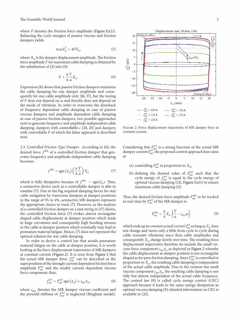
3.3. Test Results. The cable was excited directly by hand atits fundamental eigenfrequency at midspan. The logarithmic
decrement of mode 1 is determined when the MR damperforce is controlled by the CEC approach (9) andwhen theMRdamper is operated in the passive mode, that is, at constant𝑖actmr, as benchmark. As observed from Figure 4(a), the point-to-point logarithmic decrement hardly varies during thefree decay whereby the decay envelope is exponentiallyshaped when the CEC approach is adopted. Hence, the cabledamping is independent of amplitude as targeted by CEC.The measured mean logarithmic decrement 𝛿
meaof 8.73%
divided by the theoretically attainable value 𝛿theo (3) yieldsthe damping efficiency 𝜂 as follows:
𝜂 =𝛿mea
𝛿theo(11)
whose average value of all (four) CEC tests is approximately70%. The efficiency loss of approximately 30% relative tooptimal viscous damping (2) is explained by the cableflexural rigidity and fixed supported ends of the strand underconsideration whereby approximately only 80% of 𝛿theo canbe expected [39]. This loss of approximately 20% is alsoconfirmed by the difference of approximately 19% at 4% of thecable length [40] between the mode shapes of a cable withoutflexural rigidity and simply supported ends and a cable withflexural rigidity and fixed supported ends.The remaining 10%of losses are interpreted as the sum of losses due to forcetracking errors and due to the small bearing play (which ismandatory!) of both hinged joints of the damper that reducethe effective damper motion.
When the MR damper is operated in the passivemode (Figure 4(b)), the point-to-point logarithmic decre-ment strongly depends on amplitude due to the uncontrolled,that is, constant, friction force amplitude 𝐹act
mr as long as thedamper works (section 1). Within section 2, the constantfriction force amplitude 𝐹act
mr starts to lock the cable at damperposition that is confirmed by 𝑥
𝑎. At the beginning of section
3, the cable can be considered to be fully locked by theuncontrolled 𝐹act
mr whereby the cable vibrates as the casewithout external damper and 𝛿mea(𝑡
𝑖) converges towards the
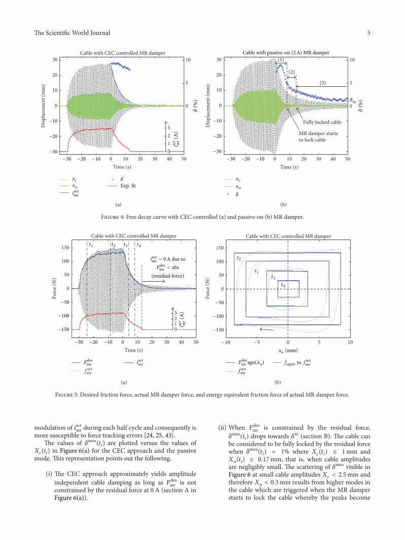
inherent logarithmic decrement 𝛿in ≈ 1%.The real-time force tracking depicted in Figure 5(a) shows
that 𝐹actmr is smaller than max(𝑓act
mr ), due to the peak forcewhich occurs at the end of each half damper cycle; seeFigure 5(b). The force tracking accuracy is assessed by thecomparison of 𝐹des
mr multiplied by sgn(��𝑎) (measured ��
𝑎) to
get the blue force displacement trajectories with the frictionforce 𝑓equiv which is the energy equivalent of the actual(measured) MR damper force 𝑓act
mr and computed as follows:
𝑓equiv = sgn (��𝑎) {
1
4𝑋𝑎
∫𝑇𝑑
0
𝑓actmr ��𝑎𝑑𝑡} . (12)
The numerical comparison of 𝑓equiv with 𝐹desmr sgn(��𝑎) within
the four selected time windows yields the average forcetracking error of 5.72%. This fairly small force tracking erroris the direct result of the CEC approach which ends upin 𝑖actmr = constant during each half cycle in contrast to, forexample, the emulation of viscous damping that requires fast
The Scientific World Journal 5
Cable with CEC controlled MR damper
0 10 20 30 40 50
0
10
20
30
Time (s)
Disp
lace
men
t (m
m)
10
5
0
321
−30
−20
−10
−30 −20 −10
𝛿(%
)
iact
mr
(A)
0
xcxa
iactmr
𝛿Exp. fit
(a)
0 10 20 30 40 50
0
10
20
30
Time (s)
Disp
lace
men
t (m
m)
10
5
0
MR damper startsto lock cable
(1)
(2)
(3)
Fully locked cable
𝛿(%
)
Cable with passive-on (2A) MR damper
−30
−20
−10
−30 −20 −10
𝛿in
xcxa
𝛿
(b)
Figure 4: Free decay curve with CEC controlled (a) and passive-on (b) MR damper.
0
50
100
150
Forc
e (N
)
0 10 20 30 40 50Time (s)
3210
Cable with CEC controlled MR damper
−150
−100
−50
−30 −20 −10
t1 t2 t3 t4
iactmr = 0A due toFdes
mr < abs
iact
mr
(A)
(residual force)
iactmr
factmr
Fdesmr
(a)
0 5 10
0
50
100
150
Forc
e (N
)
Cable with CEC controlled MR damper
−150
−100
−50
−10 −5
t1
t2
t3t4
fequiv to factmrFdes
mr sgn( a)x
factmr
xa (mm)
(b)
Figure 5: Desired friction force, actual MR damper force, and energy equivalent friction force of actual MR damper force.
modulation of 𝑖actmr during each half cycle and consequently ismore susceptible to force tracking errors [24, 25, 43].
The values of 𝛿mea(𝑡𝑖) are plotted versus the values of
𝑋𝑐(𝑡𝑖) in Figure 6(a) for the CEC approach and the passive
mode. This representation points out the following.
(i) The CEC approach approximately yields amplitudeindependent cable damping as long as 𝐹des
mr is notconstrained by the residual force at 0A (section A inFigure 6(a)).
(ii) When 𝐹desmr is constrained by the residual force,
𝛿mea(𝑡𝑖) drops towards 𝛿in (section B). The cable can
be considered to be fully locked by the residual forcewhen 𝛿mea(𝑡
𝑖) ≈ 1% where 𝑋
𝑐(𝑡𝑖) ≤ 1mm and
𝑋𝑎(𝑡𝑖) ≤ 0.17mm, that is, when cable amplitudes
are negligibly small. The scattering of 𝛿mea visible inFigure 6 at small cable amplitudes 𝑋
𝑐< 2.5mm and
therefore 𝑋𝑎< 0.3mm results from higher modes in
the cable which are triggered when the MR damperstarts to lock the cable whereby the peaks become

6 The Scientific World Journal
0 5 10 15 20 25 30 350
1
2
3
4
5
6
7
8
9
10 B AC
Amplitude dependent 𝛿 due touncontrolled predominant friction
damping at constant current
Xc (mm)
𝛿(%
)
𝛿in
Passive-on, 2ACEC No damper
(a)
0 5 10 15 20 25 30 350
1
2
3
4
5
6
7
8
9
10
𝛿in
𝛿(%
)
Xc (mm)
CEC (4 tests)CEC (4 tests)CEC (4 tests)CEC (4 tests)
0A0.75A1A1.5A No damper
2A2.5A3A
(b)
Figure 6: Logarithmic decrement versus cable displacement amplitude.
modulated and consequently 𝛿mea is scattered. Thiscould be avoided by stronger bandpass filtering of themeasured cable displacement 𝑥
𝑐which is not done
here in order to show the true cable response.(iii) The passive mode of the MR damper evokes strongly
amplitude dependent 𝛿mea(𝑡𝑖) due to the uncon-
trolled, that is, constant, friction force amplitude 𝐹actmr .
At point C 𝛿mea(𝑡𝑖) due to 2A and 𝛿mea(𝑡
𝑖) due to CEC
are approximately equal because 𝐹actmr resulting from
2A is correctly tuned to the actual damper amplitudewhich occurs when𝑋
𝑐≈ 18mm.
Figure 6(b) plots the curves of all passive mode tests and theresults of all (four) CEC tests. It is seen that the CEC approachtracks the maxima of the curves due to passive mode whichproves that the gain (𝜋𝑇)/(4𝑎) in (9) is correct.
4. Cable Damping Tests with Cables ofSutong Bridge
4.1. Cable Damping Tests at Fasten Nippon Steel, China.The CEC approach was developed at Empa in 2004/2005and tested by hybrid simulations at Empa in 2006 witha cylindrical MR damper as later installed on the SutongBridge. In 2007, this adaptive stay cable damping system wastested by the authors on a 228m long stay cable at FastenNippon Steel, China, which is described subsequently.
4.1.1. Test Set-Up. The stay cable was of the same type as thatinstalled on the Sutong Bridge. The cable was anchored at itsboth ends by provisional anchors, one of which is depictedin Figure 7(a).The force characteristics of the cylindrical MRdamper visible in Figure 7(b) are those shown in Figure 2where the current dependent friction force amplitude 𝐹act
mr is
highlighted by the horizontal dashed line and 𝑐mr of approxi-mately 24.7 kNs/m must not be neglected. The relevant testcable properties are given in Figure 7(c) which resulted in𝑓1≈ 0.65Hz. The cable was excited directly by hand at
the nodal point of the targeted mode. The cable responseswere measured at quarter span and damper position withaccelerometers and acquired with an 8-channel IO-board ofNI using the software LabVIEW. The real-time controller,current driver, and position sensor used for these tests wereof the same type as that later installed in the Sutong Bridge.The cable damping was measured for
(i) the three damper positions 5.95m (𝑎/𝐿 = 2.61%),6.56m (𝑎/𝐿 = 2.88%), and 7.81m (𝑎/𝐿 = 3.43%),
(ii) modes 1, 2, and 3,(iii) the CEC controlled MR damper,(iv) the MR damper in passive-off (0A) mode supposing
a power breakdown of the mains and, at the sametime, a power breakdownof the accumulators that canprovide the required power for 48 h.
4.1.2. Test Results. A selection of the free decay tests is shownin Figures 8(a), 8(b), and 9(a) for CEC, modes 1, 2, and 3,and 𝑎 = 6.56m; one test in passive-off mode is depictedin Figure 9(b). The point-to-point logarithmic decrement isevaluated within the free decay phase with 𝑖actmr > 0A whichindicates that 𝐹des
mr is not constrained by the residual forcewhereby force tracking is possible and the resulting cabledamping is determined by the CEC approach. It is observedthat, as for the tests at Empa, 𝛿mea does hardly vary whenthe desired friction force amplitude 𝐹des
mr (9) can be trackedby the actual friction force amplitude 𝐹act
mr . This is achievedfor modes 1, 2, and 3 as seen from Table 1 which proves

The Scientific World Journal 7
(a) (b)
Pos.sensor
a
L/4 = 57mL = 228m
m = 60.5 kg/mT ⋍ 5300kN
iactmr
xa
xc
Real-time controller with current driver
LabVIEW based data acquisition
(c)
Figure 7: Cable damping tests at Fasten Nippon Steel, China: provisional anchor of test cable (a); tested damper positions (b); sketch of testset-up (c).
0 20 40 60 80
0
0.5
1
1.5
Time (s)
1
0.5
0
0
5
10
Acce
lera
tion
(m/s2)
Mode 1, a = 6.56m, CEC controlled MR damper
−0.5
−1
−1.5
−20
𝛿(%
)
iact
mr=0
A an
d
Xc>1.5
m/s2
iactmr𝛿xa2
xc
iact
mr
(A)
(a)
0 10 20 30 40 50 60
0
1
2
3
Time (s)
1
0.50
0.25
0
0
5
10
.
−1
−2
−20 −10−3
Acce
lera
tion
(m/s2)
iact
mr
(A)
𝛿(%
)
iact
mr=0
A an
d
Xc>1.5
m/s2
Mode 2, a = 6.56m, CEC controlled MR damper
iactmr𝛿xa2
xc
(b)
Figure 8: Free decay tests with CEC controlled MR damper at damper position 𝑎 = 6.56m for mode 1 (a) and mode 2 (b).

8 The Scientific World Journal
0 10 20 30 40
0
1
2
3
4
Time (s)
0
5
10
1
0.50
0
Mode 3, a = 6.56m, CEC controlled MR damper
−1
−2
−3
−4
Acce
lera
tion
(m/s2)
−20 −10
iact
mr
(A)
iactmr = 0A andXc > 1.5m/s2
iactmr𝛿xa2
xc
𝛿(%
)(a)
0 10 20 30 40 50 60
0
1
2
3
4
5
Time (s)
0
5
10
−1
−2
−3
−4
−5
Acce
lera
tion
(m/s2)
−20 −10
𝛿(%
)
Mode 2, a = 6.56m, passive-off (0A) MR damper
Xc > 1.5m/s2
𝛿
xa2
xc
(b)
Figure 9: Free decay tests with CEC controlled MR damper at damper position 𝑎 = 6.56m for mode 3 (a) and with passive-off (0A) MRdamper at 𝑎 = 6.56m for mode 2.
Table 1: Measured mean logarithmic decrement due to CEC.
𝑎 (m) Mode 𝛿mea
(%) 0.8𝛿theo (%) 𝛿theo (%) 𝜂 (%)
5.951 6.94 6.56 8.20 84.632 7.68 6.56 8.20 93.663 7.97 6.56 8.20 97.20
6.561 7.49 7.23 9.04 82.852 7.75 7.23 9.04 85.733 8.11 7.23 9.04 89.71
7.811 10.44 8.61 10.76 97.032 10.19 8.61 10.76 94.703 10.63 8.61 10.76 98.79
that the CEC approach does not only lead to amplitude butalso lead to almost frequency independent cable damping asintended (see Section 2). The comparison of 𝛿
meato 0.8𝛿theo,
which is the expected value for a cable with flexural rigidityand fixed supported ends [39], yields 𝜂 > 100% which isphysically impossible. In contrast, the numbers of 𝜂which arederived with 𝛿theo = 𝜋𝑎/𝐿, that is, for a cable without flexuralrigidity and simply supported ends, are more reasonable.It is therefore concluded that the provisional anchors ofthis test cable did allow the rotation whereby the cableanchors behaved more like simply supported ends than fixedsupported ends.
According to [40], the mode shapes at approximately6.65m/228m ≈ 2.88% of 𝐿 of a cable with flexural rigidityand fixed supported ends and a cable without flexural rigidityand simply supported ends differ by approximately 23.8%.Subtracting 23.8% from the values of 𝜂 listed in Table 1 leadsto values in the range between 60% and 75% which is closeto the efficiency obtained at the Empa test cable (Section 3.3).
Thus, the force tracking errors in the Sutong MR damper areof the same order as those in the laboratory scale rotationalMR damper on the Empa cable.
The logarithmic decrement is also determined withinthe section 𝑖actmr = 0 to estimate the cable damping when𝐹desmr cannot be tracked by the MR damper due to the
residual force constraint. This evaluation is constrained to��𝑐≥ 1.5m/s2 to avoid scattering effects in 𝛿mea due to
measurement noise in ��𝑐. The values of 𝛿mea within this
range are between 4% and 7% which agree well with thevalues obtained with passive-off MR damper (Figure 9(b)).The suboptimal but not small values of 𝛿mea at 0 A resultfrom the proper design of the passive MR damper viscouscoefficient 𝑐mr of approximately 24.7 kNs/m (see Figure 2)that avoids clamping effects whereby cable vibrations are alsomitigated during a breakdown of themains and accumulatorsat the same time.
4.2. Cable Damping Tests on Sutong Bridge
4.2.1. Layout of Stay Cable Damping System. The bridgeowner decided to mitigate the longest six stay cables, thatis, cable number 29 with 𝐿 = 483m and 𝑓
1≈ 0.28Hz
to cable number 34 with 𝐿 = 543m and 𝑓1≈ 0.25Hz,
by CEC controlled MR dampers which gives in total 48CEC controlled MR dampers on the bridge. Always 12 MRdampers are connected to one centralized real-time con-troller with 12 current drivers. EachMR damper is controlledin a single control loop according to the collocated positionsensor that is mounted between MR damper cylinder andcable whereby 𝑥
𝑎is measured (Figure 10(a)).TheMRdamper
force range was model-based designed to be able to mitigatecable amplitudes of mode 1 of up to 𝐿/1700 according tothe fib bulletin 30 [9]. Cables number 10 to number 28
The Scientific World Journal 9
(a) (b)
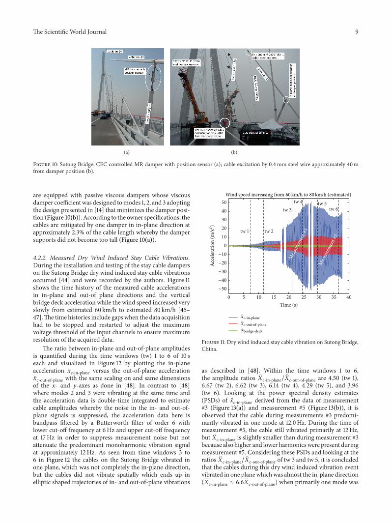
Figure 10: Sutong Bridge: CEC controlled MR damper with position sensor (a); cable excitation by 0.4mm steel wire approximately 40mfrom damper position (b).
are equipped with passive viscous dampers whose viscousdamper coefficientwas designed tomodes 1, 2, and 3 adoptingthe design presented in [14] that minimizes the damper posi-tion (Figure 10(b)). According to the owner specifications, thecables are mitigated by one damper in in-plane direction atapproximately 2.3% of the cable length whereby the dampersupports did not become too tall (Figure 10(a)).
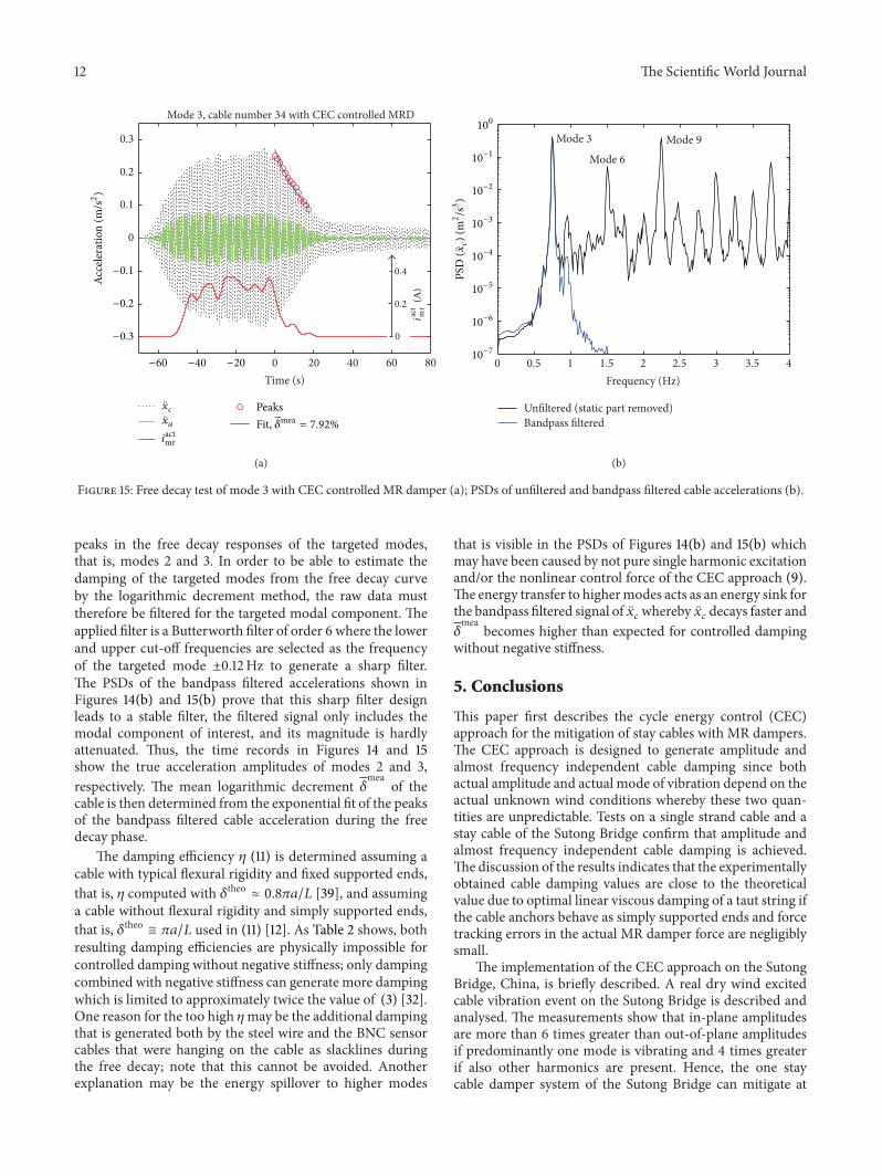
4.2.2. Measured Dry Wind Induced Stay Cable Vibrations.During the installation and testing of the stay cable damperson the Sutong Bridge dry wind induced stay cable vibrationsoccurred [44] and were recorded by the authors. Figure 11shows the time history of the measured cable accelerationsin in-plane and out-of plane directions and the verticalbridge deck acceleration while the wind speed increased veryslowly from estimated 60 km/h to estimated 80 km/h [45–47].The time histories include gaps when the data acquisitionhad to be stopped and restarted to adjust the maximumvoltage threshold of the input channels to ensure maximumresolution of the acquired data.
The ratio between in-plane and out-of-plane amplitudesis quantified during the time windows (tw) 1 to 6 of 10 seach and visualized in Figure 12 by plotting the in-planeacceleration ��
𝑐-in-plane versus the out-of-plane acceleration��𝑐-out-of-plane with the same scaling on and same dimensions
of the 𝑥- and 𝑦-axes as done in [48]. In contrast to [48]where modes 2 and 3 were vibrating at the same time andthe acceleration data is double-time integrated to estimatecable amplitudes whereby the noise in the in- and out-of-plane signals is suppressed, the acceleration data here isbandpass filtered by a Butterworth filter of order 6 withlower cut-off frequency at 6Hz and upper cut-off frequencyat 17Hz in order to suppress measurement noise but notattenuate the predominant monoharmonic vibration signalat approximately 12Hz. As seen from time windows 3 to6 in Figure 12 the cables on the Sutong Bridge vibrated inone plane, which was not completely the in-plane direction,but the cables did not vibrate spatially which ends up inelliptic shaped trajectories of in- and out-of-plane vibrations
0 5 10 15 20 25 30 35 40
01020304050
Time (s)
tw 3tw 4
tw 6
tw 2
tw 5
tw 1
Mea
sure
men
t #3
Mea
sure
men
t #5
−50
−40
−30
−20
−10
Acce
lera
tion
(m/s2)
Wind speed increasing from 60km/h to 80km/h (estimated)
-in-planexc
-out-of-planexc
bridge-deckx
Figure 11: Dry wind induced stay cable vibration on Sutong Bridge,China.
as described in [48]. Within the time windows 1 to 6,the amplitude ratios ��
𝑐-in-plane/��𝑐-out-of-plane are 4.50 (tw 1),6.67 (tw 2), 6.62 (tw 3), 6.14 (tw 4), 4.29 (tw 5), and 3.96(tw 6). Looking at the power spectral density estimates(PSDs) of ��
𝑐-in-plane derived from the data of measurement#3 (Figure 13(a)) and measurement #5 (Figure 13(b)), it isobserved that the cable during measurements #3 predomi-nantly vibrated in one mode at 12.0Hz. During the time ofmeasurement #5, the cable still vibrated primarily at 12Hz,but ��
𝑐-in-plane is slightly smaller than during measurement #3because also higher and lower harmonics were present duringmeasurement #5. Considering these PSDs and looking at theratios ��
𝑐-in-plane/��𝑐-out-of-plane of tw 3 and tw 5, it is concludedthat the cables during this dry wind induced vibration eventvibrated in one planewhichwas almost the in-plane direction(��𝑐-in-plane ≈ 6.6��
𝑐-out-of-plane) when primarily one mode was

10 The Scientific World Journal
0 1 2
0
0.5
1
1.5
2
−2 −1
−1.5
−0.5
Time window 1 (10 s)xc-
in-p
lane
(m/s2)
xc-out-of-plane (m/s2)
−2
−1
(a)
0 5
012345
−2
−3
−4
−5−5
−1
Time window 2 (10 s)
xc-
in-p
lane
(m/s2)
xc-out-of-plane (m/s2)
(b)
0 10 20 30
0
10
20
30
−20
−20−30
−30
−10
−10
xc-
in-p
lane
(m/s2)
xc-out-of-plane (m/s2)
Time window 3 (10 s)
(c)
0 50
01020304050
−30
−20
−10
−40
−50−50
Time window 4 (10 s)
xc-
in-p
lane
(m/s2)
xc-out-of-plane (m/s2)
(d)
0 20 40
010203040
Time window 5 (10 s)
−30
−20
−10
−40
−40 −20
xc-out-of-plane (m/s2)
xc-
in-p
lane
(m/s2)
(e)
0 20 40
0
10
20
30
40 Time window 6 (10 s)
−30
−20
−10
−40−40 −20
xc-
in-p
lane
(m/s2)
xc-out-of-plane (m/s2)
(f)
Figure 12: Dry wind induced stay cable vibration on Sutong Bridge, China: in-plane versus out-of-plane cable accelerations during 10 s oftime windows 1 to 6 (a–f).
excited, that is, when a resonant vibration occurred. Whenalso other harmonicswere present (tw 5, tw 6), that is, no pureresonant vibration event occurred, the cables still vibrated inone plane, but the inclination angle relative to the in-planedirection was slightly larger. Hence, large amplitude cablevibrations occurred predominantly in in-plane direction andoscillated primarily at one frequency since then all disturbingenergy excited one mode. This understanding of a typicalresonant vibration event is strengthened by the observationson the Franjo Tudjman Bridge in Croatia where a strongspring storm in 2005 led to in-plane cable vibrations ofup to 1 m midspan amplitudes [2]. Thus, the in-plane onedamper system of the Sutong Bridge can be assumed to beable to mitigate the predominant cable oscillations. It is alsounderstood that two damper systems, as, for example, thoseinstalled on the Dongting Lake Bridge [1], the ShandongBinzhou Yellow River Highway Bridge [29], or the RusskyBridge [25], are able to mitigate efficiently also the out-of-plane direction and thereby represent a more robust solutionto the problem of unpredictable cable vibrations but are alsomore costly due to the doubled number of dampers and themore complex damper supports [49, 50].
4.2.3. Test Results. The envisaged goal of the free decay testson the Sutong Bridge was to identify the cable damping ofmodes 1, 2, and 3 of selected cables with CEC controlledMR damper, with passive-off MR damper, with passive oildamper, and without damper. A 0.4mm steel wire was usedto excite the cables by two men pulling on the steel wire atthe pace of the targeted eigenfrequency using a metronome(Figure 10(b)). In order to maximize the damper motionamplitude to ensure that the CEC approach with 𝑖actmr >0A was triggered, the steel wire was placed on the cableas far away from the damper position as possible, that is,approximately 40m (Figure 10(b)).When the cable amplitudecould not be increased anymore because the excitation powerwas balanced by the dissipated power in the damper and theinherent cable damping, the steel wire was released and thenremained in hanging manner as a slackline on the stay cable tominimize additional damping by the steel wire to the cable.
The excitation of mode 1 turned out to be impossiblebecause the excitation of mode 1 requires elongating the cordlength of the cable for which the twomen powered excitationforce was too small [51]. Modes 2 and 3 could be excited tosufficient large amplitudes which evoked 𝑖actmr > 0A in the

The Scientific World Journal 11
0 10 20 30 40 50Frequency (Hz)
Measurement #3
PSD
(xc-
in-p
lane
) (m
2/s3)
105
104
103
102
101
100
10−1
10−2
10−3
Predominantmode at 12.0Hz
(a)
Measurement #5
0 10 20 30 40 50Frequency (Hz)
5.8
Hz
12.0
Hz
17.4
Hz
35.4
Hz
PSD
(xc-
in-p
lane
) (m
2/s3)
105
104
103
102
101
100
10−1
10−2
10−3
(b)
Figure 13: PSDs of in-plane acceleration of measurement #3 (a) and measurement #5 (b).
0 20 40 60 80
0
0.05
0.1
0.15
0.2
Time (s)
Mode 2, cable number 34 with CEC controlled MRD
0.5
0
0.25
Acce
lera
tion
(m/s2)
−0.05
−0.1
−0.15
−0.2−20−40−60
iact
mr
(A)
xcxa
iactmr
PeaksFit, = 9.26%𝛿mea
(a)
0 0.5 1 1.5 2 2.5 3 3.5 4Frequency (Hz)
Mode 2Mode 4
Mode 6
Mode 8 Mode 10
PSD
(xc) (
m2/s3)
100
10−1
10−2
10−3
10−4
10−5
10−6
10−7
Unfiltered (static part removed)Bandpass filtered
(b)
Figure 14: Free decay test of mode 2 with CEC controlled MR damper (a); PSDs of unfiltered and bandpass filtered cable accelerations (b).
MR damper due to the CEC approach as seen from Figures14(a) and 15(a). As seen from Figures 14(b) and 15(b), whenthe cable was excited by the steel wire at the pace of mode2 (0.497Hz), also modes 4, 6, 8, and so forth were excitedbecause the time period of mode 2 is a multiple of the time
periods of these modes. Similarly, the excitation of the cableat the pace of mode 3 (0.749Hz) also triggered modes 6,9, 12, and so forth since the time period of mode 3 is amultiple of the time periods of these modes. The undesiredexcitation of these higher harmonics evokes additional local
12 The Scientific World Journal
0
0.1
0.2
0.3
0 20 40 60 80Time (s)
Mode 3, cable number 34 with CEC controlled MRD
0.4
0
0.2
xcxa
iactmr
PeaksFit, = 7.92%𝛿mea
−0.1
−0.2
−0.3
−20−40−60
Acce
lera
tion
(m/s2)
iact
mr
(A)
(a)
0 0.5 1 1.5 2 2.5 3 3.5 4Frequency (Hz)
Mode 3
Mode 6Mode 9
Unfiltered (static part removed)Bandpass filtered
PSD
(xc) (
m2/s3)
100
10−1
10−2
10−3
10−4
10−5
10−6
10−7
(b)
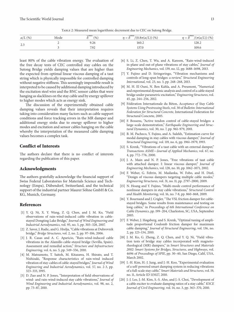
Figure 15: Free decay test of mode 3 with CEC controlled MR damper (a); PSDs of unfiltered and bandpass filtered cable accelerations (b).
peaks in the free decay responses of the targeted modes,that is, modes 2 and 3. In order to be able to estimate thedamping of the targeted modes from the free decay curveby the logarithmic decrement method, the raw data musttherefore be filtered for the targeted modal component. Theapplied filter is a Butterworth filter of order 6 where the lowerand upper cut-off frequencies are selected as the frequencyof the targeted mode ±0.12Hz to generate a sharp filter.The PSDs of the bandpass filtered accelerations shown inFigures 14(b) and 15(b) prove that this sharp filter designleads to a stable filter, the filtered signal only includes themodal component of interest, and its magnitude is hardlyattenuated. Thus, the time records in Figures 14 and 15show the true acceleration amplitudes of modes 2 and 3,respectively. The mean logarithmic decrement 𝛿
meaof the
cable is then determined from the exponential fit of the peaksof the bandpass filtered cable acceleration during the freedecay phase.
The damping efficiency 𝜂 (11) is determined assuming acable with typical flexural rigidity and fixed supported ends,that is, 𝜂 computed with 𝛿theo ≈ 0.8𝜋𝑎/𝐿 [39], and assuminga cable without flexural rigidity and simply supported ends,that is, 𝛿theo ≅ 𝜋𝑎/𝐿 used in (11) [12]. As Table 2 shows, bothresulting damping efficiencies are physically impossible forcontrolled damping without negative stiffness; only dampingcombined with negative stiffness can generate more dampingwhich is limited to approximately twice the value of (3) [32].One reason for the too high 𝜂may be the additional dampingthat is generated both by the steel wire and the BNC sensorcables that were hanging on the cable as slacklines duringthe free decay; note that this cannot be avoided. Anotherexplanation may be the energy spillover to higher modes
that is visible in the PSDs of Figures 14(b) and 15(b) whichmay have been caused by not pure single harmonic excitationand/or the nonlinear control force of the CEC approach (9).The energy transfer to highermodes acts as an energy sink forthe bandpass filtered signal of ��
𝑐whereby ��
𝑐decays faster and
𝛿mea
becomes higher than expected for controlled dampingwithout negative stiffness.
5. Conclusions
This paper first describes the cycle energy control (CEC)approach for the mitigation of stay cables with MR dampers.The CEC approach is designed to generate amplitude andalmost frequency independent cable damping since bothactual amplitude and actual mode of vibration depend on theactual unknown wind conditions whereby these two quan-tities are unpredictable. Tests on a single strand cable and astay cable of the Sutong Bridge confirm that amplitude andalmost frequency independent cable damping is achieved.The discussion of the results indicates that the experimentallyobtained cable damping values are close to the theoreticalvalue due to optimal linear viscous damping of a taut string ifthe cable anchors behave as simply supported ends and forcetracking errors in the actual MR damper force are negligiblysmall.
The implementation of the CEC approach on the SutongBridge, China, is briefly described. A real dry wind excitedcable vibration event on the Sutong Bridge is described andanalysed. The measurements show that in-plane amplitudesare more than 6 times greater than out-of-plane amplitudesif predominantly one mode is vibrating and 4 times greaterif also other harmonics are present. Hence, the one staycable damper system of the Sutong Bridge can mitigate at
The Scientific World Journal 13
Table 2: Measured mean logarithmic decrement due to CEC on Sutong Bridge.
𝑎/𝐿 (%) Mode 𝛿mea
(%) 𝜂 = 𝛿mea/(0.8𝜋(𝑎/𝐿)) (%) 𝜂 = 𝛿
mea/(𝜋(𝑎/𝐿)) (%)
2.3 2 9.26 160.2 128.23 7.92 137.0 109.6
least 80% of the cable vibration energy. The evaluation ofthe free decay tests of CEC controlled stay cables on theSutong Bridge yields damping values that are higher thanthe expected from optimal linear viscous damping of a tautstring which is physically impossible for controlled dampingwithout negative stiffness.This seemingly impossible result isinterpreted to be caused by additional damping introduced bythe excitation steel wire and the BNC sensor cables that werehanging as slacklines on the stay cable and by energy spilloverto higher modes which acts as energy sink.
The discussion of the experimentally obtained cabledamping values reveals that their interpretation requirestaking into consideration many factors such as cable supportconditions and force tracking errors in the MR damper andadditional energy sinks due to energy spillover to highermodes and excitation and sensor cables hanging on the cablewhereby the interpretation of the measured cable dampingvalues becomes a complex task.
Conflict of Interests
The authors declare that there is no conflict of interestsregarding the publication of this paper.
Acknowledgments
The authors gratefully acknowledge the financial support ofSwiss Federal Laboratories for Materials Science and Tech-nology (Empa), Dubendorf, Switzerland, and the technicalsupport of the industrial partnerMaurer Sohne GmbH&Co.KG, Munich, Germany.
References
[1] Y. Q. Ni, X. Y. Wang, Z. Q. Chen, and J. M. Ko, “Fieldobservations of rain-wind-induced cable vibration in cable-stayed Dongting Lake Bridge,” Journal of Wind Engineering andIndustrial Aerodynamics, vol. 95, no. 5, pp. 303–328, 2007.
[2] Z. Savor, J. Radic, and G. Hrelja, “Cable vibrations at Dubrovnikbridge,” Bridge Structures, vol. 2, no. 2, pp. 97–106, 2006.
[3] J. R. Casas and A. C. Aparicio, “Rain-wind-induced cablevibrations in the Alamillo cable-stayed bridge (Sevilla, Spain).Assessment and remedial action,” Structure and InfrastructureEngineering, vol. 6, no. 5, pp. 549–556, 2010.
[4] M. Matsumoto, T. Saitoh, M. Kitazawa, H. Shirato, and T.Nishizaki, “Response characteristics of rain-wind inducedvibration of stay-cables of cable-stayed bridges,” Journal ofWindEngineering and Industrial Aerodynamics, vol. 57, no. 2-3, pp.323–333, 1995.
[5] D. Zuo and N. P. Jones, “Interpretation of field observations ofwind- and rain-wind-induced stay cable vibrations,” Journal ofWind Engineering and Industrial Aerodynamics, vol. 98, no. 2,pp. 73–87, 2010.
[6] S. Li, Z. Chen, T. Wu, and A. Kareem, “Rain-wind-inducedin-plane and out-of-plane vibrations of stay cables,” Journal ofEngineering Mechanics, vol. 139, no. 12, pp. 1688–1698, 2013.
[7] Y. Fujino and D. Siringoringo, “Vibration mechanisms andcontrols of long-span bridges: a review,” Structural EngineeringInternational, vol. 23, no. 3, pp. 248–268, 2013.
[8] M. H. El Ouni, N. Ben Kahla, and A. Preumont, “Numericaland experimental dynamic analysis and control of a cable stayedbridge under parametric excitation,”Engineering Structures, vol.45, pp. 244–256, 2012.
[9] Federation Internationale du Beton, Acceptance of Stay CableSystemsUsing Prestressing Steels, vol. 30 ofBulletin: InternationalFederation for Structural Concrete, International Federation forStructural Concrete, 2005.
[10] F. Bossens, “Active tendon control of cable-stayed bridges: alarge-scale demonstration,” Earthquake Engineering and Struc-tural Dynamics, vol. 30, no. 7, pp. 961–979, 2001.
[11] B. M. Pacheco, Y. Fujino, and A. Sulekh, “Estimation curve formodal damping in stay cables with viscous damper,” Journal ofStructural Engineering, vol. 119, no. 6, pp. 1961–1979, 1993.
[12] S. Krenk, “Vibrations of a taut cable with an external damper,”Transactions ASME—Journal of Applied Mechanics, vol. 67, no.4, pp. 772–776, 2000.
[13] J. A. Main and N. P. Jones, “Free vibrations of taut cablewith attached damper. I: linear viscous damper,” Journal ofEngineering Mechanics, vol. 128, no. 10, pp. 1062–1071, 2002.
[14] F. Weber, G. Feltrin, M. Maslanka, W. Fobo, and H. Distl,“Design of viscous dampers targeting multiple cable modes,”Engineering Structures, vol. 31, no. 11, pp. 2797–2800, 2009.
[15] N. Hoang and Y. Fujino, “Multi-mode control performance ofnonlinear dampers in stay cable vibrations,” Structural Controland Health Monitoring, vol. 16, no. 7-8, pp. 860–868, 2009.
[16] Y. Bournand and J. Crigler, “The VSL friction damper for cable-stayed bridges. Some results from maintenance and testing onlong cables,” in Proceedings of 6th International Conference onCable Dynamics, pp. 199–204, Charleston, SC, USA, September2005.
[17] F. Weber, J. Høgsberg, and S. Krenk, “Optimal tuning of ampli-tude proportional Coulomb friction damper for maximumcable damping,” Journal of Structural Engineering, vol. 136, no.2, pp. 123–134, 2010.
[18] J. M. Ko, G. Zheng, Z. Q. Chen, and Y. Q. Ni, “Field vibra-tion tests of bridge stay cables incorporated with magneto-rheological (MR) dampers,” in Smart Structures and Materials2002: Smart Systems for Bridges, Structures, and Highways, vol.4696 of Proceedings of SPIE, pp. 30–40, San Diego, Calif, USA,March 2002.
[19] I.-H. Kim, H.-J. Jung, and J.-H. Koo, “Experimental evaluationof a self-powered smart damping system in reducing vibrationsof a full-scale stay cable,” SmartMaterials and Structures, vol. 19,no. 11, Article ID 115027, 2010.
[20] J.-J. Lee, J.-M. Kim, S.-S. Ahn, and J.-S. Choi, “Development ofa cable exciter to evaluate damping ratios of a stay cable,” KSCEJournal of Civil Engineering, vol. 14, no. 3, pp. 363–370, 2010.

14 The Scientific World Journal
[21] H. J. Zhou and L. M. Sun, “Damping of stay cable with passive-on magnetorheological dampers: a full-scale test,” InternationalJournal of Civil Engineering, vol. 11, no. 3, pp. 154–159, 2013.
[22] F.Weber andC. Boston, “Energy based optimization of viscous-friction dampers on cables,” SmartMaterials and Structures, vol.19, no. 4, Article ID 045025, 2010.
[23] F. Weber, H. Distl, G. Feltrin, and M. Motavalli, “Cycle energycontrol of magnetorheological dampers on cables,” SmartMate-rials and Structures, vol. 18, no. 1, Article ID 015005, 16 pages,2009.
[24] M. Maslanka, B. Sapinski, and J. Snamina, “Experimental studyof vibration control of a cable with an attached MR damper,”Journal of Theoretical and Applied Mechanics, vol. 45, no. 4, pp.893–917, 2007.
[25] F. Weber and H. Distl, “Amplitude and frequency independentcable damping of Sutong Bridge and Russky Bridge by MRdampers,” Structural Control and HealthMonitoring, vol. 22, no.2, pp. 237–254, 2015.
[26] Y. F. Duan, Y. Q. Ni, and J. M. Ko, “State-derivative feedbackcontrol of cable vibration using semiactive magnetorheologicaldampers,”Computer-Aided Civil and Infrastructure Engineering,vol. 20, no. 6, pp. 431–449, 2005.
[27] R. E. Christenson, B. F. Spencer Jr., and E. A. Johnson,“Experimental verification of smart cable damping,” Journal ofEngineering Mechanics, vol. 132, no. 3, pp. 268–278, 2006.
[28] Y. F. Duan, Y. Q. Ni, and J. M. Ko, “Cable vibration control usingmagnetorheological dampers,” Journal of Intelligent MaterialSystems and Structures, vol. 17, no. 4, pp. 321–325, 2006.
[29] H. Li, M. Liu, J. Li, X. Guan, and J. Ou, “Vibration control ofstay cables of the shandong binzhou yellow river highway bridgeusing magnetorheological fluid dampers,” Journal of BridgeEngineering, vol. 12, no. 4, pp. 401–409, 2007.
[30] H. Li, M. Liu, and J. Ou, “Negative stiffness characteristicsof active and semi-active control systems for stay cables,”Structural Control and HealthMonitoring, vol. 15, no. 2, pp. 120–142, 2008.
[31] W. J. Wu and C. S. Cai, “Cable vibration control with a semi-active MR damper-numerical simulation and experimentalverification,” Structural Engineering and Mechanics, vol. 34, no.5, pp. 611–623, 2010.
[32] C. Boston, F. Weber, and L. Guzzella, “Optimal semi-activedamping of cables: evolutionary algorithms and closed-formsolutions,” Smart Materials and Structures, vol. 18, no. 5, ArticleID 055006, 9 pages, 2009.
[33] F. Weber and C. Boston, “Clipped viscous damping with neg-ative stiffness for semi-active cable damping,” Smart Materialsand Structures, vol. 20, no. 4, Article ID 045007, 2011.
[34] F. Weber, “Bouc-Wen model-based real-time force trackingscheme for MR dampers,” Smart Materials and Structures, vol.22, no. 4, Article ID 045012, 12 pages, 2013.
[35] F. Weber, C. Boston, and M. Maslanka, “An adaptive tunedmass damper based on the emulation of positive and negativestiffness with an MR damper,” Smart Materials and Structures,vol. 20, no. 1, Article ID 015012, 2011.
[36] F. Weber and M. Maslanka, “Precise stiffness and dampingemulation with MR dampers and its application to semi-activetunedmass dampers ofWolgogradBridge,” SmartMaterials andStructures, vol. 23, no. 1, Article ID 015019, 2014.
[37] H. Bachmann, W. J. Ammann, F. Deischl et al., VibrationProblems in Structures: Practical Guidelines, Birkhauser, Basel,Switzerland, 1995.
[38] C. Glaeser, W. Brand, E. Kuhn, and T. MacK, “Testing, moni-toring andmaintenance of parallel strand cables—example: elbebridge schoenebeck,” Beton- und Stahlbetonbau, vol. 109, no. 7,pp. 463–472, 2014.
[39] N. Hoang and Y. Fujino, “Analytical study on bending effects ina stay cable with a damper,” Journal of Engineering Mechanics,vol. 133, no. 11, pp. 1241–1246, 2007.
[40] C. Boston, F. Weber, and L. Guzzella, “Optimal semi-activedamping of cables with bending stiffness,” Smart Materials andStructures, vol. 20, no. 5, Article ID 055005, 2011.
[41] M. Liu and G. Zhang, “Damping of stay cable-passive dampersystem with effects of cable bending stiffness and damperstiffness,” Applied Mechanics and Materials, vol. 204-208, pp.4513–4517, 2012.
[42] D.-H. Dan, Y.-Y. Chen, and R. Xiao, “On damping optimizationof stay cable-damper system in consideration of design andimplementation factors,” Journal of Vibration Engineering, vol.27, no. 2, pp. 246–254, 2014.
[43] F. Weber, “Robust force tracking control scheme for MRdampers,” Structural Control and Health Monitoring. In press.
[44] H. Wang, A. Li, J. Niu, Z. Zong, and J. Li, “Long-term moni-toring of wind characteristics at Sutong Bridge site,” Journal ofWind Engineering and Industrial Aerodynamics, vol. 115, pp. 39–47, 2013.
[45] Y. L. Xu andZ.Yu, “Mitigation of three-dimensional vibration ofinclined sag cable using discrete oil dampers—II. Application,”Journal of Sound andVibration, vol. 214, no. 4, pp. 675–693, 1998.
[46] F. Magalhaes, E. Caetano, A. Cunha, O. Flamand, and G. Gril-laud, “Ambient and free vibration tests of the Millau Viaduct:evaluation of alternative processing strategies,” EngineeringStructures, vol. 45, pp. 372–384, 2012.
[47] S. Li, Z. Chen, T. Wu, and A. Kareem, “Rain-wind-inducedin-plane and out-of-plane vibrations of stay cables,” Journal ofEngineering Mechanics, vol. 139, no. 12, pp. 1688–1698, 2013.
[48] D. Zuo and N. P. Jones, “Interpretation of field observations ofwind- and rain-wind-induced stay cable vibrations,” Journal ofWind Engineering and Industrial Aerodynamics, vol. 98, no. 2,pp. 73–87, 2010.
[49] F.Weber, “Design of a passive two dash-pot damping system forspatial cable vibrations,” SmartMaterials and Structures, vol. 22,no. 6, Article ID 067001, p. 5, 2013.
[50] H. Zhou, L. Sun, and F. Xing, “Damping of full-scale stay cablewith viscous damper: experiment and analysis,” Advances inStructural Engineering, vol. 17, no. 2, pp. 265–274, 2014.
[51] S. Krenk and J. R. Høgsberg, “Damping of cables by a transverseforce,” Journal of Engineering Mechanics, vol. 131, no. 4, pp. 340–348, 2005.

International Journal of
AerospaceEngineeringHindawi Publishing Corporationhttp://www.hindawi.com Volume 2014
RoboticsJournal of
Hindawi Publishing Corporationhttp://www.hindawi.com Volume 2014
Hindawi Publishing Corporationhttp://www.hindawi.com Volume 2014
Active and Passive Electronic Components
Control Scienceand Engineering
Journal of
Hindawi Publishing Corporationhttp://www.hindawi.com Volume 2014
International Journal of
RotatingMachinery
Hindawi Publishing Corporationhttp://www.hindawi.com Volume 2014
Hindawi Publishing Corporation http://www.hindawi.com
Journal ofEngineeringVolume 2014
Submit your manuscripts athttp://www.hindawi.com
VLSI Design
Hindawi Publishing Corporationhttp://www.hindawi.com Volume 2014
Hindawi Publishing Corporationhttp://www.hindawi.com Volume 2014
Shock and Vibration
Hindawi Publishing Corporationhttp://www.hindawi.com Volume 2014
Civil EngineeringAdvances in
Acoustics and VibrationAdvances in
Hindawi Publishing Corporationhttp://www.hindawi.com Volume 2014
Hindawi Publishing Corporationhttp://www.hindawi.com Volume 2014
Electrical and Computer Engineering
Journal of
Advances inOptoElectronics
Hindawi Publishing Corporation http://www.hindawi.com
Volume 2014
The Scientific World JournalHindawi Publishing Corporation http://www.hindawi.com Volume 2014
SensorsJournal of
Hindawi Publishing Corporationhttp://www.hindawi.com Volume 2014
Modelling & Simulation in EngineeringHindawi Publishing Corporation http://www.hindawi.com Volume 2014
Hindawi Publishing Corporationhttp://www.hindawi.com Volume 2014
Chemical EngineeringInternational Journal of Antennas and
Propagation
International Journal of
Hindawi Publishing Corporationhttp://www.hindawi.com Volume 2014
Hindawi Publishing Corporationhttp://www.hindawi.com Volume 2014
Navigation and Observation
International Journal of
Hindawi Publishing Corporationhttp://www.hindawi.com Volume 2014
DistributedSensor Networks
International Journal of