Embed Size (px)
Citation preview

Research ArticleEstimation of Parasitic Resistance of Electrolytic Capacitorand Filter Inductor and Prediction of Input Filter InducedOscillations in a Switch-Mode Magnet Power Supply
Rajul Lal Gour1 Mangesh Borage2 Alok Singh2 and Sunil Tiwari2
1Department of Electrical Engineering Jabalpur Engineering College Jabalpur Madhya Pradesh India2Power Supplies and Industrial Accelerator Division Raja Ramanna Centre for Advanced Technology Indore Madhya Pradesh India
Correspondence should be addressed to Rajul Lal Gour rajul1230rediffcom
Received 30 June 2016 Revised 27 September 2016 Accepted 1 November 2016
Academic Editor Don Mahinda Vilathgamuwa
Copyright copy 2016 Rajul Lal Gour et alThis is an open access article distributed under the Creative Commons Attribution Licensewhich permits unrestricted use distribution and reproduction in any medium provided the original work is properly cited
In switch-mode power converters with large ratings it is important to be able to predict the parasitic resistances associated withcircuit elements such as electrolytic capacitor and filter inductor in the initial converter design stage itself to avoid the cost and timeassociated with actual design prototype fabrication and testing of these components Knowing the values of parasitic elements isalso important as they decide the possibility of closed-loop instability besides affecting the other circuit parameters In this papera way to estimate the equivalent series resistance of electrolytic capacitor and the winding resistance of filter inductor is proposedleading to their closed form expressions in terms of system parameters Using these procedure to predict the closed-loop instabilityinduced due to the input filter is exemplified with illustrative calculations
1 Introduction
In particle accelerators various magnets are used to bendfocus and steer the beam of high energy charged particlessuch that the particles aremaintained on the desired path andin the desired orbit [1] These magnets namely dipole mag-net quadrupole magnet sextupole magnet and so forth aremostly electromagnets in which the magnetic field producedis proportional to the current flowing in their coilsThereforea large number of current controlled power supplies are usedto feed the coils of electromagnets These magnet powersupplies apart from being output current controlled havesome special characteristics as compared to general purposepower supplies Since the strength and quality of themagneticfield produced by the electromagnet depend on the currentpassing through it the output current stability of the magnetpower supply is required to be of the order of 10 to 1000parts per million (ppm) The power supply is required to beoperated inDC slow ramped or pulsedmode and sometimesrequired to track the set value The load is inductive andsince it is always connected in the circuit the load resistance
variations are minor small changes are induced only becauseof the change in operating temperatures
A large number of topologies have been used to developmagnet power supplies The choices of topologies depend onthe output power rating and other operational requirementsMultipulse thyristor rectifiers [2] transistor series pass linearregulators with preregulators switch-mode power supplieswith high-frequency isolation transformer [3] and switch-mode power converter with line frequency isolation [4ndash8]have been generally used Every architecture has its ownmerits and demerits The switch-mode power converter withline frequency isolation (called the chopper-type converter) isone of themostwidely used topologymainly due to simplicityand ruggedness [4ndash8] The block diagram of chopper-typeconverter is shown in Figure 1The converter is fed through arectifier which is followed by a second-order filter consistingof inductance 119871119891 and capacitance 119862119891 A three-phase trans-former (not shown in the diagram) precedes the rectifier tostep down the line voltage tomatch itwith the required outputDC voltage 119881119900 and DC output current 119868119900 across the magnetload with the AC mains voltage An insulated gate bipolar
Hindawi Publishing CorporationAdvances in Power ElectronicsVolume 2016 Article ID 7609103 9 pageshttpdxdoiorg10115520167609103
2 Advances in Power Electronics
Lf
Ll
Cf
Cd3-phase
Rectifier
++
+C
C
G
E
L
D
Rd
Rl
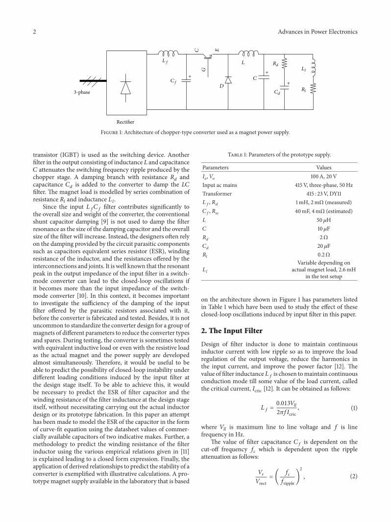
Figure 1 Architecture of chopper-type converter used as a magnet power supply
transistor (IGBT) is used as the switching device Anotherfilter in the output consisting of inductance 119871 and capacitance119862 attenuates the switching frequency ripple produced by thechopper stage A damping branch with resistance 119877119889 andcapacitance 119862119889 is added to the converter to damp the 119871119862filter The magnet load is modelled by series combination ofresistance 119877119897 and inductance 119871 119897
Since the input 119871119891119862119891 filter contributes significantly tothe overall size and weight of the converter the conventionalshunt capacitor damping [9] is not used to damp the filterresonance as the size of the damping capacitor and the overallsize of the filter will increase Instead the designers often relyon the damping provided by the circuit parasitic componentssuch as capacitors equivalent series resistor (ESR) windingresistance of the inductor and the resistances offered by theinterconnections and joints It is well known that the resonantpeak in the output impedance of the input filter in a switch-mode converter can lead to the closed-loop oscillations ifit becomes more than the input impedance of the switch-mode converter [10] In this context it becomes importantto investigate the sufficiency of the damping of the inputfilter offered by the parasitic resistors associated with itbefore the converter is fabricated and tested Besides it is notuncommon to standardize the converter design for a group ofmagnets of different parameters to reduce the converter typesand spares During testing the converter is sometimes testedwith equivalent inductive load or even with the resistive loadas the actual magnet and the power supply are developedalmost simultaneously Therefore it would be useful to beable to predict the possibility of closed-loop instability underdifferent loading conditions induced by the input filter atthe design stage itself To be able to achieve this it wouldbe necessary to predict the ESR of filter capacitor and thewinding resistance of the filter inductance at the design stageitself without necessitating carrying out the actual inductordesign or its prototype fabrication In this paper an attempthas been made to model the ESR of the capacitor in the formof curve-fit equation using the datasheet values of commer-cially available capacitors of two indicative makes Further amethodology to predict the winding resistance of the filterinductor using the various empirical relations given in [11]is explained leading to a closed form expression Finally theapplication of derived relationships to predict the stability of aconverter is exemplified with illustrative calculations A pro-totype magnet supply available in the laboratory that is based
Table 1 Parameters of the prototype supply
Parameters Values119868119900 119881119900 100A 20VInput ac mains 415V three-phase 50HzTransformer 415 23V DY11119871119891 119877119904119897 1mH 2mΩ (measured)119862119891 119877119904119888 40mF 4mΩ (estimated)119871 50 120583H119862 10 120583F119877119889 2Ω119862119889 20 120583F119877119897 02Ω119871 119897
Variable depending onactual magnet load 26mH
in the test setup
on the architecture shown in Figure 1 has parameters listedin Table 1 which have been used to study the effect of theseclosed-loop oscillations induced by input filter in this paper
2 The Input Filter
Design of filter inductor is done to maintain continuousinductor current with low ripple so as to improve the loadregulation of the output voltage reduce the harmonics inthe input current and improve the power factor [12] Thevalue of filter inductance119871119891 is chosen tomaintain continuousconduction mode till some value of the load current calledthe critical current 119868cric [12] It can be obtained as follows
119871119891 = 00131198811198971198972120587119891119868cric (1)
where 119881119897119897 is maximum line to line voltage and 119891 is linefrequency in Hz
The value of filter capacitance 119862119891 is dependent on thecut-off frequency 119891119888 which is dependent upon the rippleattenuation as follows
119881119903119881rect= ( 119891119888119891ripple)
2
(2)
Advances in Power Electronics 3
Rsl Lf
Cf3-phase
Rectifier
Zo+
Rsc
Figure 2 Input filter with parasitic resistances
where 119881119903 is the ripple voltage at the output of 119871119891119862119891 filter119881rect is the unfiltered rectifier voltage and 119891ripple is the ripplefrequency at the output of the rectifier The ratio (119881119903119881rect) orthe attenuation required is governed by the allowable currentin the magnet load at the ripple frequency Having decidedthe value of filter cut-off frequency 119891119888 the value of filtercapacitor is defined by
119862119891 = 1412058721198912119888 119871119891 (3)
Figure 2 shows the input filter section of the circuit shownin Figure 1 The ESR of capacitor 119877119904119888 and winding resis-tance of the inductor 119877119904119897 are explicitly shown The outputimpedance 119885119900 of the filter in terms of the filter componentscan be derived as follows
119885119900 = 1198711198911198621198911198771199041198881199042 + (119871119891 + 119862119891119877119904119888119877119904119897) 119904 + 1198771199041198971198711198911198621198911199042 + 119862119891 (119877119904119888 + 119877119904119897) 119904 + 1 (4)
A typical plot of (4) is shown in Figure 3 exhibiting peakingat the resonant frequency The maximum output impedance119885119900 (max) can be derived as
119885119900 (max) = 119871119891 + 119862119891119877119904119888119877119904119897119862119891 (119877119904119888 + 119877119904119897) (5)
As the large value of output impedance of the input filtercan deteriorate the audio susceptibility of the supply andcause the closed-loop oscillations under certain conditionsthis filter has to be damped to reduce the peak resonance [9]A common passive way of damping is to use shunt capacitordamping [9] which is generally used in the damping ofthe output 119871119862 filter of the chopper as shown in Figure 1The values of filter component are small and the value andsize of additional damping capacitor 119862119889 become practicallymanageable
On the other hand in case of the input filter cut-offfrequency is typically 20ndash30Hz or lower if the output currentstability specification of the power supply is stringent Sincethe magnet power supplies are typically low-voltage high-current type the value of filter capacitance is already largeand it becomes practically difficult to provide shunt capacitordamping The damping therefore is solely offered by thecircuit parasitic components 119877119904119888 and 119877119904119897
minus80minus60minus40minus20
020
Mag
nitu
de (d
B)
minus90minus45
04590
Phas
e (de
g)
100 101 102 103 104 10510minus1
Frequency (Hz)
100 101 102 103 104 10510minus1
Frequency (Hz)
Figure 3 Plot of (4) showing the variation of output impedance ofthe input filter as a function of frequency (119871119891 = 1mH 119862119891 = 40mF119877119904119888 = 4mΩ 119877119904119897 = 1mΩ)
3 Input Impedance ofthe Switch-Mode Converter
It has been shown that a potential problem of closed-loopinstability arises when the output impedance of the inputfilter becomes large than the input impedance of the switch-mode converter To study how this input filter affects theoverall response of the system the effect of the input filterimpedance on the transfer function of the system has to betaken into account This can be done using Middlebrookrsquosextra element theorem [9] According to which the modifiedtransfer function of the system on addition of the extraelement can be deduced by
1198661015840 (119904) = 119866119901 (119904) (1 + 119885119900 (119904) 119885119873 (119904))(1 + 119885119900 (119904) 119885119863 (119904)) (6)
where 1198661015840(119904) is the modified duty cycle to output transferfunction of the converter with input filter and 119866119901(119904) is theduty cycle to output transfer function of converter withoutthe input filter given by
119866119901 (119904) = 119881119889 (1198861119904 + 1) (1198862119904 + 1)11990111199044 + 11990121199043 + 11990131199042 + 1199014119904 + 1 (7)
where
1198861 = 1198621198891198771198891198862 = 119871 1198971198771198971199011 = 119862119871119862119889119877119889119871 1198971198771198971199012 = (119862119871119862119889119877119889 + 119862119871119871 119897119877119897 + 119871119862119889119871 119897119877119897 )
4 Advances in Power Electronics
100 101 102 103 104 10510minus1
Frequency (Hz)
100 101 102 103 104 10510minus1
Frequency (Hz)
minus90minus45
04590
Phas
e (de
g)
minus20minus10
010203040
Mag
nitu
de (d
B)
(a)
100 101 102 103 104 10510minus1
Frequency (Hz)
100 101 102 103 104 10510minus1
Frequency (Hz)
minus200
20406080
Mag
nitu
de (d
B)
180
225
270
Phas
e (de
g)
(b)
Figure 4 Plots of (9) and (11) showing (a) typical variation in 119885119863 and (b) typical variation in 119885119873 (119871 = 50 120583H 119862 = 10 120583F 119862119889 = 50 120583F119877119889 = 2Ω 119871 119897 = 26mH 119877119897 = 01Ω)
1199013 = (119862119871 + 119871119862119889119877119889119877119897 + 119871119862119889 + 119871 119897119862119889119877119889119877119897 )
1199014 = (119871119862119889119877119889119877119897 + 119871119877119897 +
119871 119897119877119897) (8)
with 119871 119862 119862119889 119877119889 119871 119897 and 119877119897 being the converter parametersshown in Figure 1119885119900(119904) is the output impedance of the input filter given by(4)119885119863(119904) also known as driving point impedance is theThevenin equivalent impedance seen from the converterinput side with input set to zero [9] For the converter shownin Figure 1 it can be derived as follows
119885119863 (119904) = 11198892 (
11986011199044 + 11986021199043 + 11986031199042 + 1198604119904 + 11987711989711986111199043 + 11986121199042 + 1198613119904 + 1 ) (9)
where 119889 is the duty cycle of the converter and
1198601 = 119871119871 1198971198771198891198621198621198891198602 = (119871119871 119897119862119889 + 119871119877119897119877119889119862119889119862 + 119871119871 119897119862)1198603 = (119862119889119871 119897119877119889 + 119862119889119871119877119897 + 119862119889119871119877119889 + 119862119871119877119897)1198604 = (119871 + 119871 119897 + 119862119889119877119897119877119889)1198611 = 119871 1198971198771198891198621198891198621198612 = (119871 119897119862119889 + 119871 119897119862 + 119877119897119877119889119862119889119862)1198613 = (119877119889119862119889 + 119877119897119862 + 119877119897119862119889)
(10)
119885119873(119904) is the impedance seen through the input port withinput voltage nulled to zero [9] For the converter shown inFigure 1 it can be derived as follows
119885119873 (119904) = minus 11198892 (119877119897 + 119871 119897 (119904)) (11)
Typical plots of (9) and (11) are shown in Figure 4 From (9)and (11) it can be inferred that both 119885119863(119904) and 119885119873(119904) aredependent on the duty cycle of the converterThe closed-loopinstability occurs when output impedance of filter is greaterthan the input impedance of SMPS [10] As the duty cycleof switch-mode converter is increased 119885119863 and 119885119873 decreaseTherefore the highest duty cycle (119889 = 1) is considered asthe worst case for design 119885119863 and 119885119873 also depend on theinductance and resistance values of the magnet load Figure 5shows the plots of119885119863 illustratively for different combinationsof 119877119897 and 119871 119897 (119871 119897 = 100mH 26mH and 119877119897 = 01Ω)superimposed on 119885119900 (119871119891 = 1mH 119862119891 = 40mF 119877119904119888 = 4mΩ119877119904119897 = 1mΩ) The graphs with different values of load induc-tance are shown to emphasize the effect of load inductanceon stability From the plots it can be observed that a highinductive load ensures the stability of the regulator becausethe high inductance offers high input impedance even at thelow frequencies However with loads with lower inductanceand the pure resistive load the system may become unstableTherefore the resistive load case at the maximum duty cyclebecomes the worst case conditions as far as the possibilityof input filter induced oscillations is concerned Thus thecondition for stability can be stated as follows
119885119900 (max) le 119877119897 (12)
Since the value of 119885119900 (max) given by (5) depends alsoon 119877119904119897 and 119877119904119888 besides the values of 119871119891 and 119862119891 it would benecessary to be able to predict 119877119904119897 and 119877119904119888 at the design stageitself without necessitating to carry out the actual inductordesign or its prototype fabrication
4 Estimation of Capacitor ESR
Electrolytic capacitors are commonly used as the filter capac-itor in the front end mains rectifier circuits In this section anattempt tomodel the ESR of filter capacitor is presented basedon the datasheet values of commercially available capacitorsESR of a capacitor is the sum of resistance of dielectric plate
Advances in Power Electronics 5
minus90minus45
04590
Phas
e (de
g)
minus100minus50
050
100
Mag
nitu
de (d
B)
Zo
ZD(Rl = 01 ohm Ll = 26mH)ZD(Rl = 01 ohm Ll = 100mH)
ZD(Rl = 01 ohm)
Zo
ZD(Rl = 01 ohm Ll = 26mH)ZD(Rl = 01 ohm Ll = 100mH)
ZD(Rl = 01 ohm)
100 101 102 103 104 10510minus1
Frequency (Hz)
100 101 102 103 104 10510minus1
Frequency (Hz)
Figure 5 Impedance of regulator with inductive and resistive load(119871 = 50 120583H 119862 = 10 120583F 119862119889 = 50 120583F 119877119889 = 2Ω 119871 119897 = 100mH26mH 119877119897 = 01Ω)
material electrolytic solution and lead terminals Duringthe design of the filter the ESR values determine how muchAC ripple current can the capacitor withstand The ESR of acapacitor also depends on its value voltage rating maximumdatasheet temperature type of construction ripple currentrating manufacturer and so forth Therefore perhaps it isdifficult to obtain a unique relationship that would describethe ESR of a capacitor as a function of its value alone
The relationship between ESR and the capacitance valueis studied by analyzing datasheet values of various capacitorsof two representative makes (Make-X and Make-Y) rated for100V 200V 450V and 85∘C with screw terminals Firstlythe datasheet values of ESR of the individual capacitors areplotted as a function of capacitance value for different voltageratings (as shown by the 998779 and I markers in Figure 6) Sec-ondly it is a commonpractice to use capacitor banks inwhichvarious capacitors are connected in parallel either because asingle capacitorwith required value voltage rating and ripplecurrent rating is not available or to increase the ripple currentrating or to reduce ESR Therefore the capacitor banks inwhich maximum up to 10 identical capacitors are connectedin parallel are also considered The calculated effective ESRvalue of such banks is also plotted as a function of effectivecapacitance (as shown by ◻ and loz in Figure 6) In principlethe capacitor banks in which capacitors are connected inseries can also be considered for data generation Howeversuch capacitor banks are not commonly encountered since amagnet power supply is typically a low-voltage high-currenttype and therefore not considered in Figure 6 The results are
Table 2 Values of coefficients 119860 and 119861Capacitor voltage rating 119860 119861100V 31 times 10minus4 079200V 3509 times 10minus4 0816450V 3864 times 10minus4 0769
summarized in Figure 6 for 100V 200V and 450V screwterminal electrolytic capacitors rated for 85∘C
From Figure 6 it can be observed that the relationshipbetween 119877119904119888 and 119862119891 can be expressed in following generalform
119877119904119888 = 119860119862(minus119861)119891 (13)
where coefficients119860 and119861 for different voltage ratings of elec-trolytic capacitors of different voltage ratings are tabulated inTable 2 By following the generalmethod described above onecan obtain the relationship between ESR and the capacitancevalue for capacitors of the required voltage rating
The ESR 119877119904119888 can be written in terms of system parametersfrom (1) (3) and (13)
119877119904119888 = 119860(37035119891119868cric1205871198811198971198971198912119888 )minus119861
(14)
which further can be alternatively arranged as follows
119877119904119888 = 119860(50119891 (119868cric119868119900)1205871198912119888 )minus119861
(119877119897)119861 (15)
where 119868119900 is the rated output currentThus the ESR of the filtercapacitor can be predicted from the above relationships
5 Estimation of InductorrsquosWinding Resistance
Various empirical relationships that can be used to predict thevolume and surface area of an inductor are given in [11] basedon function of many parameters such as inductance valuecurrent operating flux density current density temperaturerise and core configuration Using these relationships thefollowing derivation is proposed to predict the windingresistance of an inductor at the design stage itself usingvarious system parameters and without having to design theactual inductor or to prototype it
The value of input filter inductor 119871119891 is fixed based on (1)The total energy stored by the inductor is related to the areaproduct 119860119901 given by [11]
119860119901 = (2119864 times 104119896119906119896119895119861119898 )
114
(16)
where 119861119898 is the maximum flux density (just before satura-tion) and 119896119895 is a constant related to core configuration [11]119864 isenergy stored in inductor and 119896119906 is window utilization factor
Energy stored in inductor is given by
119864 = 121198711198911198682119900 (17)
6 Advances in Power Electronics
Curve fit equation
0
001
002
003
004
005
006
007
008
009ES
R (Ω
)
001 01 10001Capacitance (F)
ESR = 31 times 10minus4C(minus079)
Individual capacitors of Make-XParallel combination of capacitors of Make-XIndividual capacitors of Make-YParallel combination of capacitors of Make-Y
(a)
0
001
002
003
004
005
006
007
008
009
01
ESR
(Ω)
001 01 10001Capacitance (F)
ESR = 3059 times 10minus4C(minus0816)
Curve fit equation
Individual capacitors of Make-XParallel combination of capacitors of Make-XIndividual capacitors of Make-YParallel combination of capacitors of Make-Y
(b)
0
001
002
003
004
005
006
007
008
009
ESR
(Ω)
001 01 10001Capacitance (F)
ESR = 3846 times 10minus4C(minus0769)
Individual capacitors of Make-XParallel combination of capacitors of Make-XIndividual capacitors of Make-YParallel combination of capacitors of Make-YCurve fit equation
(c)
Figure 6 Relationship between ESR and capacitance value of electrolytic capacitors obtained for (a) 100V (b) 200V and (c) 450V screwterminal electrolytic capacitors rated for 85∘C
Substituting the value of 119871119891 from (1) in (17) we get
119864 = 12 (001311988111989711989711986821199002120587119891119868cric ) (18)
Now substituting the value of 119864 from (18) in (16) we get
119860119901 = ( 13011988111989711989711986821199002120587119891119868cric119896119906119896119895119861119898)114
(19)
During operation due to the presence of parasitic wind-ing resistance 119877119904119897 some energy is lost in the form of heatDue to these copper losses the temperature of the inductorincreases The rise in temperature Δ119879 of surface area 119860 119905is related to the copper losses incurred by the inductor asfollows
1198682119900119877119904119897 = 119860 119905120595 (20)
Advances in Power Electronics 7
where 120595 is temperature constant given by
Δ119879 = 450 (120595)0826 (21)
Typically120595 = 007 forΔ119879 = 50∘ and120595 = 003 forΔ119879 = 25∘CFurther the surface area 119860 119905 of the inductor is also related
to the area product as [11]
119860 119905 = 119896119904radic119860119901 (22)
where 119896119904 is a constant dependent on the core configurationThe value of 119896119904 and 119896119895 for different types of core is given in [11]
Substituting value of 119860119901 from (19) in (22) we get
119860 119905 = 119896119904 ( 13011988111989711989711986821199002120587119891119868cric119896119906119896119895119861119898)057
(23)
And from (20) and (23) we get
1198682119900119877119904119897 = 120595119896119904 ( 13011988111989711989711986821199002120587119891119868cric119896119906119896119895119861119898)057
(24)
Hence the winding resistance 119877119904119897 of the filter inductor interms of the system parameters can be given as follows
119877119904119897 = 120595119896119904 (119868119900)(minus086) ( 1301198811198971198972120587119891119896119906119896119895119861119898119868cric)057
(25)
The above equation can be alternatively written in terms ofrated output power 119875119900 and rated output current 119868119900 as
119877119904119897 = 120595119896119904 (119868119900)(minus2) ( 1001198751199002120587119891119896119906119896119895119861119898 (119868cric119868119900))057
(26)
6 Predicting Possibility ofClosed-Loop Oscillations
The previous sections deal with the estimation of parasiticresistors associated with electrolytic capacitor and filterinductor These parasitic resistors along with other parasiticresistors such as those of interconnecting wires and bus barsand joints offer damping to the filter The other parasiticresistance due to interconnections and joints can be neglectedsafely as they will offer additional damping If the dampingoffered by 119877119904119888 and 119877119904119897 is sufficient to satisfy inequality of(12) the closed-loop system will be stable else the input filtercan induce closed-loop oscillations This is exemplified withillustrative calculations in this section for a converter whosemajor parameters are listed in Tables 3 and 1 For the designof input filter the ratio (119868cric119868119900) is used as an independentvariable Electrolytic capacitors of 100V rating are consideredfor estimation The calculations are done using a spreadsheetprogram with the following steps
(i) Calculate 119871119891 using (1)(ii) Calculate 119862119891 using (3)(iii) Calculate 119877119904119897 using (25)(iv) Calculate 119877119904119888 using (14)
Table 3 Parameters of converter for illustrative calculations
Parameters Values119881119897119897 23V119891 50Hz119891119888 25Hz119861119898 1 T119896119895 366 [11]119896119904 392 [11]119896119906 04 [11]120595 003 [11]119868119900 100A119881119900 20V
Filte
r ind
ucto
r (H
) ESR
(Ω) w
indi
ng
resis
tanc
e (Ω) fi
lter c
apac
itanc
e (F)
Winding resistance of inductor (ohm)
01 1001IcricIo
1E minus 05
1E minus 03
1E minus 01
1E + 01
Filter inductance Lf (H)ESR of capacitor (ohm)Filter capacitance Cf (F)
Figure 7 Variation of filter parameters with 119868cric
The results of the calculations are summarized in Figure 7From Figure 7 it can be observed that as the value of criticalinductor current 119868cric increases the value of filter capacitanceincreases as it is directly proportional to 119868cric whereas valueof filter inductor and the parasitic resistances 119877119904119897 and 119877119904119888decrease This is due to the inverse relation between theseparameters and 119868cric Next the value of119885119900 (max) is calculatedfrom (5) and summarized in Figure 8 It can be observedthat as the value of critical current 119868cric increases the outputimpedance of the system decreases The critical conditionariseswhen119885119900 (max) becomes equal to the resistance as givenby (12) In the present case the converter will be stable if119868cric119868119900 is chosen to be more than 007 To verify the resultsof Figure 8 two illustrative operating points in the unstableregion (case I 119868cric119868119900 = 002) and the stable region (case II119868cric119868119900 = 01) are selected Calculated values of the variousparameters are listed in Table 4 The plots of control-to-output transfer function calculated using (6)ndash(11) and puttingparameters from Tables 1 and 4 for these two cases are shownin Figure 9 It can be clearly seen that the system is unstablein case I and stable in case II
8 Advances in Power Electronics
Stable region
Rl
01 1001IcricIo
0
05
1
15
2
25
3
Zo
(max
)(Ω
)
Zo (max)
Figure 8 Variation of 119885119900 (max) with 119868cric
minus30minus20minus10
010203040
Mag
nitu
de (d
B)
minus180minus90
090
180270360
Phas
e (de
g)
101 102 103 104 105
Frequency (Hz)
101 102 103 104 105
Frequency (Hz)
(a)
minus30minus20minus10
0102030
Mag
nitu
de (d
B)
minus180
minus90
0
90
Phas
e (de
g)
101 102 103 104 105
Frequency (Hz)
101 102 103 104 105
Frequency (Hz)
(b)
Figure 9 Control-to-output transfer function of in (a) case I and (b) case II
Table 4 Parameters for calculation of control-to-output transferfunction
Parameter Case I Case II119868cric119868119900 002 01119885119900 (max) 098Ω 011Ω119871119891 476 120583H 952 120583H119862119891 0085 F 0425 F119877119904119897 34mΩ 13mΩ119877119904119888 22mΩ 627mΩ
7 Conclusion
An ability to estimate ESR of electrolytic capacitors andwinding resistance of inductor used in front end input filterthereby enabling the prediction of possibility of a closed-loop instability in a magnet power supply in the design stageitself is of great practical importance A way to estimatethe capacitor ESR using datasheet values of commerciallyavailable capacitors and winding resistance of the filter
inductor using empirical relationships is proposed in thispaper that resulted in closed form expressions used to identifythe stable operating region of the converter using simplespreadsheet calculations
Disclosure
Rajul Lal Gour carried out M Tech project work atPower Supplies and Industrial Accelerator Division of RajaRamanna Centre for Advanced Technology Indore duringDecember 2015 to June 2016
Competing Interests
The authors declare that they have no competing interests
References
[1] P J Bryant ldquoPerformance requirements for acceleratorsrdquo inProceedings of the Power Converters for Particle AcceleratorsHyatt Conference Montreux Switzerland March 1990
Advances in Power Electronics 9
[2] A Elkiaeligr C Nielsen A Jensen and C Soslashrensen ldquoLow voltagehigh current SCR controlled magnet power supplyrdquo in Pro-ceedings of the 2nd International Particle Accelerator Conference(IPAC rsquo11) Kyoto Japan 2011
[3] X Qi and Z Xu Resonant Magnet Power Supply System for theRapid Cycle Synchrotron of Chinese Spallation Neutron SourceAPAC Proceedings Gyeongju Korea 2004
[4] F Long ldquoStatus and trends in magnet power converter tech-nology for acceleratorrdquo in Proceedings of the 5th InternationalParticle Accelerator Conference (IPAC rsquo14) Dresden Germany2014
[5] J-CHuang Y-SWong andK-B Liu ldquoImprovement of outputcurrent characteristics for BIRA MCOR30 correction magnetpower supplyrdquo in Proceedings of the IPAC San Sebastian SpainSeptember 2011
[6] YHuaihai Z ZhongzuG Yaling et al ldquoA design of switchmag-net power supplyrdquo in Proceedings of the 19th International Con-ference on Cyclotrons and Their Applications (CYCLOTRONSrsquo10) Institute of Modern Physics Chinese Academy of ScienceLanzhou China September 2010
[7] S C Kim S H Ahn J C Yoon J M Kim C D Park and KR Kim ldquoMagnet power supplies performance at PSL-II storageringrdquo in Proceedings of the IPAC Pohang Korea 2016
[8] S H Jeong K-H Park H S Suh et al ldquoStatus of the fabricationof PAL-XFELmagnet power suppliesrdquo inProceedings of the FELDaejeon Korea 2015
[9] R D Middlebrook and S Cuk Advances in Switched-ModePower Conversion Volume I and II TESLAco 2nd edition 1983
[10] R W Ercikson and D Maksimovic Fundamentals of PowerElectronics Springer Berlin Germany 2nd edition 2001
[11] C W T McLyman Transformer and Inductor Handbook PHI2nd edition 2003
[12] NMohan TMUndeland andWP RobbinsPower ElectronicsConverter Application and Design John Wiley amp Sons NewYork NY USA 3rd edition 2002
International Journal of
AerospaceEngineeringHindawi Publishing Corporationhttpwwwhindawicom Volume 2014
RoboticsJournal of
Hindawi Publishing Corporationhttpwwwhindawicom Volume 2014
Hindawi Publishing Corporationhttpwwwhindawicom Volume 2014
Active and Passive Electronic Components
Control Scienceand Engineering
Journal of
Hindawi Publishing Corporationhttpwwwhindawicom Volume 2014
International Journal of
RotatingMachinery
Hindawi Publishing Corporationhttpwwwhindawicom Volume 2014
Hindawi Publishing Corporation httpwwwhindawicom
Journal ofEngineeringVolume 2014
Submit your manuscripts athttpwwwhindawicom
VLSI Design
Hindawi Publishing Corporationhttpwwwhindawicom Volume 2014
Hindawi Publishing Corporationhttpwwwhindawicom Volume 2014
Shock and Vibration
Hindawi Publishing Corporationhttpwwwhindawicom Volume 2014
Civil EngineeringAdvances in
Acoustics and VibrationAdvances in
Hindawi Publishing Corporationhttpwwwhindawicom Volume 2014
Hindawi Publishing Corporationhttpwwwhindawicom Volume 2014
Electrical and Computer Engineering
Journal of
Advances inOptoElectronics
Hindawi Publishing Corporation httpwwwhindawicom
Volume 2014
The Scientific World JournalHindawi Publishing Corporation httpwwwhindawicom Volume 2014
SensorsJournal of
Hindawi Publishing Corporationhttpwwwhindawicom Volume 2014
Modelling amp Simulation in EngineeringHindawi Publishing Corporation httpwwwhindawicom Volume 2014
Hindawi Publishing Corporationhttpwwwhindawicom Volume 2014
Chemical EngineeringInternational Journal of Antennas and
Propagation
International Journal of
Hindawi Publishing Corporationhttpwwwhindawicom Volume 2014
Hindawi Publishing Corporationhttpwwwhindawicom Volume 2014
Navigation and Observation
International Journal of
Hindawi Publishing Corporationhttpwwwhindawicom Volume 2014
DistributedSensor Networks
International Journal of
2 Advances in Power Electronics
Lf
Ll
Cf
Cd3-phase
Rectifier
++
+C
C
G
E
L
D
Rd
Rl
Figure 1 Architecture of chopper-type converter used as a magnet power supply
transistor (IGBT) is used as the switching device Anotherfilter in the output consisting of inductance 119871 and capacitance119862 attenuates the switching frequency ripple produced by thechopper stage A damping branch with resistance 119877119889 andcapacitance 119862119889 is added to the converter to damp the 119871119862filter The magnet load is modelled by series combination ofresistance 119877119897 and inductance 119871 119897
Since the input 119871119891119862119891 filter contributes significantly tothe overall size and weight of the converter the conventionalshunt capacitor damping [9] is not used to damp the filterresonance as the size of the damping capacitor and the overallsize of the filter will increase Instead the designers often relyon the damping provided by the circuit parasitic componentssuch as capacitors equivalent series resistor (ESR) windingresistance of the inductor and the resistances offered by theinterconnections and joints It is well known that the resonantpeak in the output impedance of the input filter in a switch-mode converter can lead to the closed-loop oscillations ifit becomes more than the input impedance of the switch-mode converter [10] In this context it becomes importantto investigate the sufficiency of the damping of the inputfilter offered by the parasitic resistors associated with itbefore the converter is fabricated and tested Besides it is notuncommon to standardize the converter design for a group ofmagnets of different parameters to reduce the converter typesand spares During testing the converter is sometimes testedwith equivalent inductive load or even with the resistive loadas the actual magnet and the power supply are developedalmost simultaneously Therefore it would be useful to beable to predict the possibility of closed-loop instability underdifferent loading conditions induced by the input filter atthe design stage itself To be able to achieve this it wouldbe necessary to predict the ESR of filter capacitor and thewinding resistance of the filter inductance at the design stageitself without necessitating carrying out the actual inductordesign or its prototype fabrication In this paper an attempthas been made to model the ESR of the capacitor in the formof curve-fit equation using the datasheet values of commer-cially available capacitors of two indicative makes Further amethodology to predict the winding resistance of the filterinductor using the various empirical relations given in [11]is explained leading to a closed form expression Finally theapplication of derived relationships to predict the stability of aconverter is exemplified with illustrative calculations A pro-totype magnet supply available in the laboratory that is based
Table 1 Parameters of the prototype supply
Parameters Values119868119900 119881119900 100A 20VInput ac mains 415V three-phase 50HzTransformer 415 23V DY11119871119891 119877119904119897 1mH 2mΩ (measured)119862119891 119877119904119888 40mF 4mΩ (estimated)119871 50 120583H119862 10 120583F119877119889 2Ω119862119889 20 120583F119877119897 02Ω119871 119897
Variable depending onactual magnet load 26mH
in the test setup
on the architecture shown in Figure 1 has parameters listedin Table 1 which have been used to study the effect of theseclosed-loop oscillations induced by input filter in this paper
2 The Input Filter
Design of filter inductor is done to maintain continuousinductor current with low ripple so as to improve the loadregulation of the output voltage reduce the harmonics inthe input current and improve the power factor [12] Thevalue of filter inductance119871119891 is chosen tomaintain continuousconduction mode till some value of the load current calledthe critical current 119868cric [12] It can be obtained as follows
119871119891 = 00131198811198971198972120587119891119868cric (1)
where 119881119897119897 is maximum line to line voltage and 119891 is linefrequency in Hz
The value of filter capacitance 119862119891 is dependent on thecut-off frequency 119891119888 which is dependent upon the rippleattenuation as follows
119881119903119881rect= ( 119891119888119891ripple)
2
(2)
Advances in Power Electronics 3
Rsl Lf
Cf3-phase
Rectifier
Zo+
Rsc
Figure 2 Input filter with parasitic resistances
where 119881119903 is the ripple voltage at the output of 119871119891119862119891 filter119881rect is the unfiltered rectifier voltage and 119891ripple is the ripplefrequency at the output of the rectifier The ratio (119881119903119881rect) orthe attenuation required is governed by the allowable currentin the magnet load at the ripple frequency Having decidedthe value of filter cut-off frequency 119891119888 the value of filtercapacitor is defined by
119862119891 = 1412058721198912119888 119871119891 (3)
Figure 2 shows the input filter section of the circuit shownin Figure 1 The ESR of capacitor 119877119904119888 and winding resis-tance of the inductor 119877119904119897 are explicitly shown The outputimpedance 119885119900 of the filter in terms of the filter componentscan be derived as follows
119885119900 = 1198711198911198621198911198771199041198881199042 + (119871119891 + 119862119891119877119904119888119877119904119897) 119904 + 1198771199041198971198711198911198621198911199042 + 119862119891 (119877119904119888 + 119877119904119897) 119904 + 1 (4)
A typical plot of (4) is shown in Figure 3 exhibiting peakingat the resonant frequency The maximum output impedance119885119900 (max) can be derived as
119885119900 (max) = 119871119891 + 119862119891119877119904119888119877119904119897119862119891 (119877119904119888 + 119877119904119897) (5)
As the large value of output impedance of the input filtercan deteriorate the audio susceptibility of the supply andcause the closed-loop oscillations under certain conditionsthis filter has to be damped to reduce the peak resonance [9]A common passive way of damping is to use shunt capacitordamping [9] which is generally used in the damping ofthe output 119871119862 filter of the chopper as shown in Figure 1The values of filter component are small and the value andsize of additional damping capacitor 119862119889 become practicallymanageable
On the other hand in case of the input filter cut-offfrequency is typically 20ndash30Hz or lower if the output currentstability specification of the power supply is stringent Sincethe magnet power supplies are typically low-voltage high-current type the value of filter capacitance is already largeand it becomes practically difficult to provide shunt capacitordamping The damping therefore is solely offered by thecircuit parasitic components 119877119904119888 and 119877119904119897
minus80minus60minus40minus20
020
Mag
nitu
de (d
B)
minus90minus45
04590
Phas
e (de
g)
100 101 102 103 104 10510minus1
Frequency (Hz)
100 101 102 103 104 10510minus1
Frequency (Hz)
Figure 3 Plot of (4) showing the variation of output impedance ofthe input filter as a function of frequency (119871119891 = 1mH 119862119891 = 40mF119877119904119888 = 4mΩ 119877119904119897 = 1mΩ)
3 Input Impedance ofthe Switch-Mode Converter
It has been shown that a potential problem of closed-loopinstability arises when the output impedance of the inputfilter becomes large than the input impedance of the switch-mode converter To study how this input filter affects theoverall response of the system the effect of the input filterimpedance on the transfer function of the system has to betaken into account This can be done using Middlebrookrsquosextra element theorem [9] According to which the modifiedtransfer function of the system on addition of the extraelement can be deduced by
1198661015840 (119904) = 119866119901 (119904) (1 + 119885119900 (119904) 119885119873 (119904))(1 + 119885119900 (119904) 119885119863 (119904)) (6)
where 1198661015840(119904) is the modified duty cycle to output transferfunction of the converter with input filter and 119866119901(119904) is theduty cycle to output transfer function of converter withoutthe input filter given by
119866119901 (119904) = 119881119889 (1198861119904 + 1) (1198862119904 + 1)11990111199044 + 11990121199043 + 11990131199042 + 1199014119904 + 1 (7)
where
1198861 = 1198621198891198771198891198862 = 119871 1198971198771198971199011 = 119862119871119862119889119877119889119871 1198971198771198971199012 = (119862119871119862119889119877119889 + 119862119871119871 119897119877119897 + 119871119862119889119871 119897119877119897 )
4 Advances in Power Electronics
100 101 102 103 104 10510minus1
Frequency (Hz)
100 101 102 103 104 10510minus1
Frequency (Hz)
minus90minus45
04590
Phas
e (de
g)
minus20minus10
010203040
Mag
nitu
de (d
B)
(a)
100 101 102 103 104 10510minus1
Frequency (Hz)
100 101 102 103 104 10510minus1
Frequency (Hz)
minus200
20406080
Mag
nitu
de (d
B)
180
225
270
Phas
e (de
g)
(b)
Figure 4 Plots of (9) and (11) showing (a) typical variation in 119885119863 and (b) typical variation in 119885119873 (119871 = 50 120583H 119862 = 10 120583F 119862119889 = 50 120583F119877119889 = 2Ω 119871 119897 = 26mH 119877119897 = 01Ω)
1199013 = (119862119871 + 119871119862119889119877119889119877119897 + 119871119862119889 + 119871 119897119862119889119877119889119877119897 )
1199014 = (119871119862119889119877119889119877119897 + 119871119877119897 +
119871 119897119877119897) (8)
with 119871 119862 119862119889 119877119889 119871 119897 and 119877119897 being the converter parametersshown in Figure 1119885119900(119904) is the output impedance of the input filter given by(4)119885119863(119904) also known as driving point impedance is theThevenin equivalent impedance seen from the converterinput side with input set to zero [9] For the converter shownin Figure 1 it can be derived as follows
119885119863 (119904) = 11198892 (
11986011199044 + 11986021199043 + 11986031199042 + 1198604119904 + 11987711989711986111199043 + 11986121199042 + 1198613119904 + 1 ) (9)
where 119889 is the duty cycle of the converter and
1198601 = 119871119871 1198971198771198891198621198621198891198602 = (119871119871 119897119862119889 + 119871119877119897119877119889119862119889119862 + 119871119871 119897119862)1198603 = (119862119889119871 119897119877119889 + 119862119889119871119877119897 + 119862119889119871119877119889 + 119862119871119877119897)1198604 = (119871 + 119871 119897 + 119862119889119877119897119877119889)1198611 = 119871 1198971198771198891198621198891198621198612 = (119871 119897119862119889 + 119871 119897119862 + 119877119897119877119889119862119889119862)1198613 = (119877119889119862119889 + 119877119897119862 + 119877119897119862119889)
(10)
119885119873(119904) is the impedance seen through the input port withinput voltage nulled to zero [9] For the converter shown inFigure 1 it can be derived as follows
119885119873 (119904) = minus 11198892 (119877119897 + 119871 119897 (119904)) (11)
Typical plots of (9) and (11) are shown in Figure 4 From (9)and (11) it can be inferred that both 119885119863(119904) and 119885119873(119904) aredependent on the duty cycle of the converterThe closed-loopinstability occurs when output impedance of filter is greaterthan the input impedance of SMPS [10] As the duty cycleof switch-mode converter is increased 119885119863 and 119885119873 decreaseTherefore the highest duty cycle (119889 = 1) is considered asthe worst case for design 119885119863 and 119885119873 also depend on theinductance and resistance values of the magnet load Figure 5shows the plots of119885119863 illustratively for different combinationsof 119877119897 and 119871 119897 (119871 119897 = 100mH 26mH and 119877119897 = 01Ω)superimposed on 119885119900 (119871119891 = 1mH 119862119891 = 40mF 119877119904119888 = 4mΩ119877119904119897 = 1mΩ) The graphs with different values of load induc-tance are shown to emphasize the effect of load inductanceon stability From the plots it can be observed that a highinductive load ensures the stability of the regulator becausethe high inductance offers high input impedance even at thelow frequencies However with loads with lower inductanceand the pure resistive load the system may become unstableTherefore the resistive load case at the maximum duty cyclebecomes the worst case conditions as far as the possibilityof input filter induced oscillations is concerned Thus thecondition for stability can be stated as follows
119885119900 (max) le 119877119897 (12)
Since the value of 119885119900 (max) given by (5) depends alsoon 119877119904119897 and 119877119904119888 besides the values of 119871119891 and 119862119891 it would benecessary to be able to predict 119877119904119897 and 119877119904119888 at the design stageitself without necessitating to carry out the actual inductordesign or its prototype fabrication
4 Estimation of Capacitor ESR
Electrolytic capacitors are commonly used as the filter capac-itor in the front end mains rectifier circuits In this section anattempt tomodel the ESR of filter capacitor is presented basedon the datasheet values of commercially available capacitorsESR of a capacitor is the sum of resistance of dielectric plate
Advances in Power Electronics 5
minus90minus45
04590
Phas
e (de
g)
minus100minus50
050
100
Mag
nitu
de (d
B)
Zo
ZD(Rl = 01 ohm Ll = 26mH)ZD(Rl = 01 ohm Ll = 100mH)
ZD(Rl = 01 ohm)
Zo
ZD(Rl = 01 ohm Ll = 26mH)ZD(Rl = 01 ohm Ll = 100mH)
ZD(Rl = 01 ohm)
100 101 102 103 104 10510minus1
Frequency (Hz)
100 101 102 103 104 10510minus1
Frequency (Hz)
Figure 5 Impedance of regulator with inductive and resistive load(119871 = 50 120583H 119862 = 10 120583F 119862119889 = 50 120583F 119877119889 = 2Ω 119871 119897 = 100mH26mH 119877119897 = 01Ω)
material electrolytic solution and lead terminals Duringthe design of the filter the ESR values determine how muchAC ripple current can the capacitor withstand The ESR of acapacitor also depends on its value voltage rating maximumdatasheet temperature type of construction ripple currentrating manufacturer and so forth Therefore perhaps it isdifficult to obtain a unique relationship that would describethe ESR of a capacitor as a function of its value alone
The relationship between ESR and the capacitance valueis studied by analyzing datasheet values of various capacitorsof two representative makes (Make-X and Make-Y) rated for100V 200V 450V and 85∘C with screw terminals Firstlythe datasheet values of ESR of the individual capacitors areplotted as a function of capacitance value for different voltageratings (as shown by the 998779 and I markers in Figure 6) Sec-ondly it is a commonpractice to use capacitor banks inwhichvarious capacitors are connected in parallel either because asingle capacitorwith required value voltage rating and ripplecurrent rating is not available or to increase the ripple currentrating or to reduce ESR Therefore the capacitor banks inwhich maximum up to 10 identical capacitors are connectedin parallel are also considered The calculated effective ESRvalue of such banks is also plotted as a function of effectivecapacitance (as shown by ◻ and loz in Figure 6) In principlethe capacitor banks in which capacitors are connected inseries can also be considered for data generation Howeversuch capacitor banks are not commonly encountered since amagnet power supply is typically a low-voltage high-currenttype and therefore not considered in Figure 6 The results are
Table 2 Values of coefficients 119860 and 119861Capacitor voltage rating 119860 119861100V 31 times 10minus4 079200V 3509 times 10minus4 0816450V 3864 times 10minus4 0769
summarized in Figure 6 for 100V 200V and 450V screwterminal electrolytic capacitors rated for 85∘C
From Figure 6 it can be observed that the relationshipbetween 119877119904119888 and 119862119891 can be expressed in following generalform
119877119904119888 = 119860119862(minus119861)119891 (13)
where coefficients119860 and119861 for different voltage ratings of elec-trolytic capacitors of different voltage ratings are tabulated inTable 2 By following the generalmethod described above onecan obtain the relationship between ESR and the capacitancevalue for capacitors of the required voltage rating
The ESR 119877119904119888 can be written in terms of system parametersfrom (1) (3) and (13)
119877119904119888 = 119860(37035119891119868cric1205871198811198971198971198912119888 )minus119861
(14)
which further can be alternatively arranged as follows
119877119904119888 = 119860(50119891 (119868cric119868119900)1205871198912119888 )minus119861
(119877119897)119861 (15)
where 119868119900 is the rated output currentThus the ESR of the filtercapacitor can be predicted from the above relationships
5 Estimation of InductorrsquosWinding Resistance
Various empirical relationships that can be used to predict thevolume and surface area of an inductor are given in [11] basedon function of many parameters such as inductance valuecurrent operating flux density current density temperaturerise and core configuration Using these relationships thefollowing derivation is proposed to predict the windingresistance of an inductor at the design stage itself usingvarious system parameters and without having to design theactual inductor or to prototype it
The value of input filter inductor 119871119891 is fixed based on (1)The total energy stored by the inductor is related to the areaproduct 119860119901 given by [11]
119860119901 = (2119864 times 104119896119906119896119895119861119898 )
114
(16)
where 119861119898 is the maximum flux density (just before satura-tion) and 119896119895 is a constant related to core configuration [11]119864 isenergy stored in inductor and 119896119906 is window utilization factor
Energy stored in inductor is given by
119864 = 121198711198911198682119900 (17)
6 Advances in Power Electronics
Curve fit equation
0
001
002
003
004
005
006
007
008
009ES
R (Ω
)
001 01 10001Capacitance (F)
ESR = 31 times 10minus4C(minus079)
Individual capacitors of Make-XParallel combination of capacitors of Make-XIndividual capacitors of Make-YParallel combination of capacitors of Make-Y
(a)
0
001
002
003
004
005
006
007
008
009
01
ESR
(Ω)
001 01 10001Capacitance (F)
ESR = 3059 times 10minus4C(minus0816)
Curve fit equation
Individual capacitors of Make-XParallel combination of capacitors of Make-XIndividual capacitors of Make-YParallel combination of capacitors of Make-Y
(b)
0
001
002
003
004
005
006
007
008
009
ESR
(Ω)
001 01 10001Capacitance (F)
ESR = 3846 times 10minus4C(minus0769)
Individual capacitors of Make-XParallel combination of capacitors of Make-XIndividual capacitors of Make-YParallel combination of capacitors of Make-YCurve fit equation
(c)
Figure 6 Relationship between ESR and capacitance value of electrolytic capacitors obtained for (a) 100V (b) 200V and (c) 450V screwterminal electrolytic capacitors rated for 85∘C
Substituting the value of 119871119891 from (1) in (17) we get
119864 = 12 (001311988111989711989711986821199002120587119891119868cric ) (18)
Now substituting the value of 119864 from (18) in (16) we get
119860119901 = ( 13011988111989711989711986821199002120587119891119868cric119896119906119896119895119861119898)114
(19)
During operation due to the presence of parasitic wind-ing resistance 119877119904119897 some energy is lost in the form of heatDue to these copper losses the temperature of the inductorincreases The rise in temperature Δ119879 of surface area 119860 119905is related to the copper losses incurred by the inductor asfollows
1198682119900119877119904119897 = 119860 119905120595 (20)
Advances in Power Electronics 7
where 120595 is temperature constant given by
Δ119879 = 450 (120595)0826 (21)
Typically120595 = 007 forΔ119879 = 50∘ and120595 = 003 forΔ119879 = 25∘CFurther the surface area 119860 119905 of the inductor is also related
to the area product as [11]
119860 119905 = 119896119904radic119860119901 (22)
where 119896119904 is a constant dependent on the core configurationThe value of 119896119904 and 119896119895 for different types of core is given in [11]
Substituting value of 119860119901 from (19) in (22) we get
119860 119905 = 119896119904 ( 13011988111989711989711986821199002120587119891119868cric119896119906119896119895119861119898)057
(23)
And from (20) and (23) we get
1198682119900119877119904119897 = 120595119896119904 ( 13011988111989711989711986821199002120587119891119868cric119896119906119896119895119861119898)057
(24)
Hence the winding resistance 119877119904119897 of the filter inductor interms of the system parameters can be given as follows
119877119904119897 = 120595119896119904 (119868119900)(minus086) ( 1301198811198971198972120587119891119896119906119896119895119861119898119868cric)057
(25)
The above equation can be alternatively written in terms ofrated output power 119875119900 and rated output current 119868119900 as
119877119904119897 = 120595119896119904 (119868119900)(minus2) ( 1001198751199002120587119891119896119906119896119895119861119898 (119868cric119868119900))057
(26)
6 Predicting Possibility ofClosed-Loop Oscillations
The previous sections deal with the estimation of parasiticresistors associated with electrolytic capacitor and filterinductor These parasitic resistors along with other parasiticresistors such as those of interconnecting wires and bus barsand joints offer damping to the filter The other parasiticresistance due to interconnections and joints can be neglectedsafely as they will offer additional damping If the dampingoffered by 119877119904119888 and 119877119904119897 is sufficient to satisfy inequality of(12) the closed-loop system will be stable else the input filtercan induce closed-loop oscillations This is exemplified withillustrative calculations in this section for a converter whosemajor parameters are listed in Tables 3 and 1 For the designof input filter the ratio (119868cric119868119900) is used as an independentvariable Electrolytic capacitors of 100V rating are consideredfor estimation The calculations are done using a spreadsheetprogram with the following steps
(i) Calculate 119871119891 using (1)(ii) Calculate 119862119891 using (3)(iii) Calculate 119877119904119897 using (25)(iv) Calculate 119877119904119888 using (14)
Table 3 Parameters of converter for illustrative calculations
Parameters Values119881119897119897 23V119891 50Hz119891119888 25Hz119861119898 1 T119896119895 366 [11]119896119904 392 [11]119896119906 04 [11]120595 003 [11]119868119900 100A119881119900 20V
Filte
r ind
ucto
r (H
) ESR
(Ω) w
indi
ng
resis
tanc
e (Ω) fi
lter c
apac
itanc
e (F)
Winding resistance of inductor (ohm)
01 1001IcricIo
1E minus 05
1E minus 03
1E minus 01
1E + 01
Filter inductance Lf (H)ESR of capacitor (ohm)Filter capacitance Cf (F)
Figure 7 Variation of filter parameters with 119868cric
The results of the calculations are summarized in Figure 7From Figure 7 it can be observed that as the value of criticalinductor current 119868cric increases the value of filter capacitanceincreases as it is directly proportional to 119868cric whereas valueof filter inductor and the parasitic resistances 119877119904119897 and 119877119904119888decrease This is due to the inverse relation between theseparameters and 119868cric Next the value of119885119900 (max) is calculatedfrom (5) and summarized in Figure 8 It can be observedthat as the value of critical current 119868cric increases the outputimpedance of the system decreases The critical conditionariseswhen119885119900 (max) becomes equal to the resistance as givenby (12) In the present case the converter will be stable if119868cric119868119900 is chosen to be more than 007 To verify the resultsof Figure 8 two illustrative operating points in the unstableregion (case I 119868cric119868119900 = 002) and the stable region (case II119868cric119868119900 = 01) are selected Calculated values of the variousparameters are listed in Table 4 The plots of control-to-output transfer function calculated using (6)ndash(11) and puttingparameters from Tables 1 and 4 for these two cases are shownin Figure 9 It can be clearly seen that the system is unstablein case I and stable in case II
8 Advances in Power Electronics
Stable region
Rl
01 1001IcricIo
0
05
1
15
2
25
3
Zo
(max
)(Ω
)
Zo (max)
Figure 8 Variation of 119885119900 (max) with 119868cric
minus30minus20minus10
010203040
Mag
nitu
de (d
B)
minus180minus90
090
180270360
Phas
e (de
g)
101 102 103 104 105
Frequency (Hz)
101 102 103 104 105
Frequency (Hz)
(a)
minus30minus20minus10
0102030
Mag
nitu
de (d
B)
minus180
minus90
0
90
Phas
e (de
g)
101 102 103 104 105
Frequency (Hz)
101 102 103 104 105
Frequency (Hz)
(b)
Figure 9 Control-to-output transfer function of in (a) case I and (b) case II
Table 4 Parameters for calculation of control-to-output transferfunction
Parameter Case I Case II119868cric119868119900 002 01119885119900 (max) 098Ω 011Ω119871119891 476 120583H 952 120583H119862119891 0085 F 0425 F119877119904119897 34mΩ 13mΩ119877119904119888 22mΩ 627mΩ
7 Conclusion
An ability to estimate ESR of electrolytic capacitors andwinding resistance of inductor used in front end input filterthereby enabling the prediction of possibility of a closed-loop instability in a magnet power supply in the design stageitself is of great practical importance A way to estimatethe capacitor ESR using datasheet values of commerciallyavailable capacitors and winding resistance of the filter
inductor using empirical relationships is proposed in thispaper that resulted in closed form expressions used to identifythe stable operating region of the converter using simplespreadsheet calculations
Disclosure
Rajul Lal Gour carried out M Tech project work atPower Supplies and Industrial Accelerator Division of RajaRamanna Centre for Advanced Technology Indore duringDecember 2015 to June 2016
Competing Interests
The authors declare that they have no competing interests
References
[1] P J Bryant ldquoPerformance requirements for acceleratorsrdquo inProceedings of the Power Converters for Particle AcceleratorsHyatt Conference Montreux Switzerland March 1990
Advances in Power Electronics 9
[2] A Elkiaeligr C Nielsen A Jensen and C Soslashrensen ldquoLow voltagehigh current SCR controlled magnet power supplyrdquo in Pro-ceedings of the 2nd International Particle Accelerator Conference(IPAC rsquo11) Kyoto Japan 2011
[3] X Qi and Z Xu Resonant Magnet Power Supply System for theRapid Cycle Synchrotron of Chinese Spallation Neutron SourceAPAC Proceedings Gyeongju Korea 2004
[4] F Long ldquoStatus and trends in magnet power converter tech-nology for acceleratorrdquo in Proceedings of the 5th InternationalParticle Accelerator Conference (IPAC rsquo14) Dresden Germany2014
[5] J-CHuang Y-SWong andK-B Liu ldquoImprovement of outputcurrent characteristics for BIRA MCOR30 correction magnetpower supplyrdquo in Proceedings of the IPAC San Sebastian SpainSeptember 2011
[6] YHuaihai Z ZhongzuG Yaling et al ldquoA design of switchmag-net power supplyrdquo in Proceedings of the 19th International Con-ference on Cyclotrons and Their Applications (CYCLOTRONSrsquo10) Institute of Modern Physics Chinese Academy of ScienceLanzhou China September 2010
[7] S C Kim S H Ahn J C Yoon J M Kim C D Park and KR Kim ldquoMagnet power supplies performance at PSL-II storageringrdquo in Proceedings of the IPAC Pohang Korea 2016
[8] S H Jeong K-H Park H S Suh et al ldquoStatus of the fabricationof PAL-XFELmagnet power suppliesrdquo inProceedings of the FELDaejeon Korea 2015
[9] R D Middlebrook and S Cuk Advances in Switched-ModePower Conversion Volume I and II TESLAco 2nd edition 1983
[10] R W Ercikson and D Maksimovic Fundamentals of PowerElectronics Springer Berlin Germany 2nd edition 2001
[11] C W T McLyman Transformer and Inductor Handbook PHI2nd edition 2003
[12] NMohan TMUndeland andWP RobbinsPower ElectronicsConverter Application and Design John Wiley amp Sons NewYork NY USA 3rd edition 2002
International Journal of
AerospaceEngineeringHindawi Publishing Corporationhttpwwwhindawicom Volume 2014
RoboticsJournal of
Hindawi Publishing Corporationhttpwwwhindawicom Volume 2014
Hindawi Publishing Corporationhttpwwwhindawicom Volume 2014
Active and Passive Electronic Components
Control Scienceand Engineering
Journal of
Hindawi Publishing Corporationhttpwwwhindawicom Volume 2014
International Journal of
RotatingMachinery
Hindawi Publishing Corporationhttpwwwhindawicom Volume 2014
Hindawi Publishing Corporation httpwwwhindawicom
Journal ofEngineeringVolume 2014
Submit your manuscripts athttpwwwhindawicom
VLSI Design
Hindawi Publishing Corporationhttpwwwhindawicom Volume 2014
Hindawi Publishing Corporationhttpwwwhindawicom Volume 2014
Shock and Vibration
Hindawi Publishing Corporationhttpwwwhindawicom Volume 2014
Civil EngineeringAdvances in
Acoustics and VibrationAdvances in
Hindawi Publishing Corporationhttpwwwhindawicom Volume 2014
Hindawi Publishing Corporationhttpwwwhindawicom Volume 2014
Electrical and Computer Engineering
Journal of
Advances inOptoElectronics
Hindawi Publishing Corporation httpwwwhindawicom
Volume 2014
The Scientific World JournalHindawi Publishing Corporation httpwwwhindawicom Volume 2014
SensorsJournal of
Hindawi Publishing Corporationhttpwwwhindawicom Volume 2014
Modelling amp Simulation in EngineeringHindawi Publishing Corporation httpwwwhindawicom Volume 2014
Hindawi Publishing Corporationhttpwwwhindawicom Volume 2014
Chemical EngineeringInternational Journal of Antennas and
Propagation
International Journal of
Hindawi Publishing Corporationhttpwwwhindawicom Volume 2014
Hindawi Publishing Corporationhttpwwwhindawicom Volume 2014
Navigation and Observation
International Journal of
Hindawi Publishing Corporationhttpwwwhindawicom Volume 2014
DistributedSensor Networks
International Journal of

International Journal of
AerospaceEngineeringHindawi Publishing Corporationhttpwwwhindawicom Volume 2014
RoboticsJournal of
Hindawi Publishing Corporationhttpwwwhindawicom Volume 2014
Hindawi Publishing Corporationhttpwwwhindawicom Volume 2014
Active and Passive Electronic Components
Control Scienceand Engineering
Journal of
Hindawi Publishing Corporationhttpwwwhindawicom Volume 2014
International Journal of
RotatingMachinery
Hindawi Publishing Corporationhttpwwwhindawicom Volume 2014
Hindawi Publishing Corporation httpwwwhindawicom
Journal ofEngineeringVolume 2014
Submit your manuscripts athttpwwwhindawicom
VLSI Design
Hindawi Publishing Corporationhttpwwwhindawicom Volume 2014
Hindawi Publishing Corporationhttpwwwhindawicom Volume 2014
Shock and Vibration
Hindawi Publishing Corporationhttpwwwhindawicom Volume 2014
Civil EngineeringAdvances in
Acoustics and VibrationAdvances in
Hindawi Publishing Corporationhttpwwwhindawicom Volume 2014
Hindawi Publishing Corporationhttpwwwhindawicom Volume 2014
Electrical and Computer Engineering
Journal of
Advances inOptoElectronics
Hindawi Publishing Corporation httpwwwhindawicom
Volume 2014
The Scientific World JournalHindawi Publishing Corporation httpwwwhindawicom Volume 2014
SensorsJournal of
Hindawi Publishing Corporationhttpwwwhindawicom Volume 2014
Modelling amp Simulation in EngineeringHindawi Publishing Corporation httpwwwhindawicom Volume 2014
Hindawi Publishing Corporationhttpwwwhindawicom Volume 2014
Chemical EngineeringInternational Journal of Antennas and
Propagation
International Journal of
Hindawi Publishing Corporationhttpwwwhindawicom Volume 2014
Hindawi Publishing Corporationhttpwwwhindawicom Volume 2014
Navigation and Observation
International Journal of
Hindawi Publishing Corporationhttpwwwhindawicom Volume 2014
DistributedSensor Networks
International Journal of
![Medicago truncatula as a Model for Nonhost Resistance in Legume-Parasitic Plant Interactions1[C]](https://img.pdfslide.us/doc/110x75/61fb24ae2e268c58cd5aa846/medicago-truncatula-as-a-model-for-nonhost-resistance-in-legume-parasitic-plant.jpg)