Embed Size (px)
Citation preview

Journal of Instrumentation
Research and development of a dedicatedcollimator for 142 MeV fast neutrons for imagingusing a D-T generatorTo cite this article I Sabo-Napadensky et al 2012 JINST 7 C06005
View the article online for updates and enhancements
Recent citationsA simulation study of a fan-beam time-of-flight fast-neutron tomography systemShifeng Sun and Xiaoping Ouyang
-
Preliminary Experimentation of FastNeutron Radiography with D-T NeutronGenerator at BARCS Bishnoi et al
-
The Soreq Applied Research AcceleratorFacility (SARAF) Overview researchprograms and future plansIsrael Mardor et al
-
This content was downloaded from IP address 6521228167 on 09102021 at 0519
2012 JINST 7 C06005
PUBLISHED BY IOP PUBLISHING FOR SISSA MEDIALAB
RECEIVED December 18 2011ACCEPTED April 17 2012PUBLISHED June 11 2012
2nd INTERNATIONAL WORKSHOP ON FAST NEUTRON DETECTORS AND APPLICATIONSNOVEMBER 6ndash11 2011EIN GEDI ISRAEL
Research and development of a dedicated collimatorfor 142 MeV fast neutrons for imaging using a D-Tgenerator
I Sabo-Napadensky1 R Weiss-Babai A Gayer D Vartsky D Bar I MorR Chacham-Zada M Cohen and N Tamim
NDT Department Soreq NRCYavne Israel
E-mail irissabogmailcom
ABSTRACT One of the main problems in neutron imaging is the scattered radiation that accom-panies the direct neutrons that reach the imaging detectors and affect the image quality We havedeveloped a dedicated collimator for 142 MeV fast neutrons The collimator optimizes the amountof scattered radiation to primary neutrons that arrive at the imaging plane We have used differentmaterials within the collimator in order to lower the scattered radiation that arrives at the scannedobject The image quality and the signal to noise ratios that are measured show that a mixture ofBORAX (Na2B4O7middot10H2O) and water in the experimental beam collimator give the best resultsWe have used GEANT4 to simulate the collimator performance the simulations predict the op-timized material looking on the ratios of the scattered to primary neutrons that contribute in thedetector We present our experimental setup report the results of the experimental and relatedsimulation studies with neutrons beam generated by a 142 MeV D-T neutron generator
KEYWORDS Inspection with neutrons Detection of defects Neutron detectors (cold thermal fastneutrons) Neutron radiography
1Corresponding author
ccopy 2012 IOP Publishing Ltd and Sissa Medialab srl doi1010881748-0221706C06005
2012 JINST 7 C06005
Contents
1 Introduction 111 Scatter 112 Image Quality (IQ) parameters 213 Fan and cone beam configurations 2
2 Experimental setup 221 The upstream collimator 322 The downstream collimator 5
3 Experimental Results 531 Scatter from the scanned object 532 Lowering the scatter from the surroundings 833 Optimization of the moderating material 9
4 Simulation results 13
5 Conclusions 15
1 Introduction
Neutron imaging suffers from scatter phenomena degrading the image quality The collimation ofthe beam is a major component in the process of lowering the scatter caused by neutrons and gam-mas that accompany the primary neutrons The motivation of this work is to reduce the amount ofscattered particles that arrive to the detector to a minimum in order to maintain better image quality
11 Scatter
The most important mechanism of interaction between neutrons and the inspected object is scat-tering However the desired attenuated signal one would like to measure in the detector is theresult of primary neutrons The result of scattered neutrons that are measured in the detector isimage contrast degradation in the radiography images and artifacts such as streaks and cupping intomography images
In conventional x-ray CT this problem is mostly dealt with hardware solutions such as high Zmaterials anti-scatter grids which are part of the detecting system preventing the scattered photonsfrom reaching the detector There are also numerous attempts to solve the issue by using softwarecorrections [1ndash3] Both are complicated do not solve the problem completely and may eventu-ally induce new artifacts In the case of neutrons the hardware solution that exists for x-ray isimpossible
ndash 1 ndash
2012 JINST 7 C06005
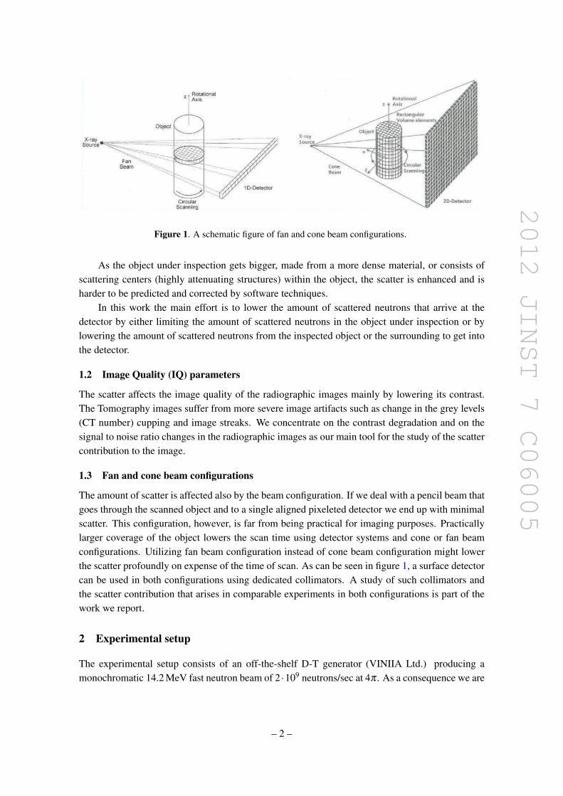
Figure 1 A schematic figure of fan and cone beam configurations
As the object under inspection gets bigger made from a more dense material or consists ofscattering centers (highly attenuating structures) within the object the scatter is enhanced and isharder to be predicted and corrected by software techniques
In this work the main effort is to lower the amount of scattered neutrons that arrive at thedetector by either limiting the amount of scattered neutrons in the object under inspection or bylowering the amount of scattered neutrons from the inspected object or the surrounding to get intothe detector
12 Image Quality (IQ) parameters
The scatter affects the image quality of the radiographic images mainly by lowering its contrastThe Tomography images suffer from more severe image artifacts such as change in the grey levels(CT number) cupping and image streaks We concentrate on the contrast degradation and on thesignal to noise ratio changes in the radiographic images as our main tool for the study of the scattercontribution to the image
13 Fan and cone beam configurations
The amount of scatter is affected also by the beam configuration If we deal with a pencil beam thatgoes through the scanned object and to a single aligned pixeleted detector we end up with minimalscatter This configuration however is far from being practical for imaging purposes Practicallylarger coverage of the object lowers the scan time using detector systems and cone or fan beamconfigurations Utilizing fan beam configuration instead of cone beam configuration might lowerthe scatter profoundly on expense of the time of scan As can be seen in figure 1 a surface detectorcan be used in both configurations using dedicated collimators A study of such collimators andthe scatter contribution that arises in comparable experiments in both configurations is part of thework we report
2 Experimental setup
The experimental setup consists of an off-the-shelf D-T generator (VINIIA Ltd) producing amonochromatic 142 MeV fast neutron beam of 2 middot109 neutronssec at 4π As a consequence we are
ndash 2 ndash
2012 JINST 7 C06005
Figure 2 The scheme of the experimental layout
limited on one hand by the flux to short distances which means more scattered neutrons arrive at thedetectors and on the other hand to smaller scanned objects which means less scattered neutrons arescattered in the object itself The generator is followed by an upstream beam collimator the scannedobject which is located at its exit is followed by a downstream collimator that serves only in thefan collimation configuration and last in the beam line follows the detection system (figures 2 3)
The detection system consists of a Polystyrene scintillating fiber array screen with an activearea of 200times200 mm 30 (or 10) mm depth and 05 (or 10) mm pixel size The neutrons arriveat the detector interact in the fiber scintillating screen producing light image Optics transfer theimage to the image-intensifier and a CCD camera views the image created at the phosphor of theimage intensifier [4]
Two phantoms are used in the experiment
1 A Point Spread Function (PSF) phantom a stainless steel cylinder shaped with a concentriccylinder hole in it (figure 4)
2 A Modulation Transfer Phantom (MTF) a box shaped stainless steel with slits in differentsizes (figure 4)
Next to the generator there is a plastic scintillator neutron detector that serves as a referencedetector for beam monitoring (figure 2)
21 The upstream collimator
The upstream collimator is a stainless steel ldquobarrelrdquo shaped container It is 1000 mm long with aradius of 275 mm and side wall of 2 mm wide material (figure 5) The cone beam defined apertureis 24ndash107 mm squared aperture at entrance and exit of the beam respectively The barrel is filled
ndash 3 ndash
2012 JINST 7 C06005
Figure 3 A picture of the experiment
Figure 4 The PSF stainless steel phantom (left) the MTF stainless steel phantom (right)
with one of the three different moderating materials examined The results for the three differentmoderating materials are compared as part of the optimization studies
In order to define the fan beam configuration a fan beam definer made of 5 borated polyethy-lene is put into the cone hole Once it is in the hole it defines a horizontal fan beam of 8 mm gapThe width of the fan beam gap was optimized in order to get maximum SNR and contrast
ndash 4 ndash
2012 JINST 7 C06005
Figure 5 The upstream collimator Illustrations of the cone beam collimator fan beam definer and fan beamcollimator
Figure 6 The downstream collimator
22 The downstream collimator
The downstream collimator (figure 6) serves mostly in the fan configuration It is a 600 mm long320times280 mm2 5 borated polyethylene collimator with a 8 mm gap It is located 150 mm down-stream of the phantom 150 mm upstream of the detector
3 Experimental Results
31 Scatter from the scanned object
The scatter effect was checked in cone configuration in several consecutive experiments in order toverify that we actually deal with scatter although the object under examination is not large
ndash 5 ndash
2012 JINST 7 C06005
Figure 7 The PSF images ldquonearrdquo (upper left image) and ldquofarrdquo (lower left image) from the detector ThePSF image profiles are shown along with enlarged relevant parts of the images respectively (right images)
Table 1 The calculated contrasts for the different phantom thicknesses with and without the addition of anattached scatterer to the phantom
Thickness ofStainless steel inMTF phantom
Contrastwithoutscatterer
Contrast withscatterer
12 cm 03plusmn1 023plusmn122 cm 022plusmn1 016plusmn1
The influence of the phantom location in respect to the detector on the image contrast ischecked (figure 7) A PSF phantom is positioned either in close proximity to the detector (ldquonearrdquo)or at the exit of the beam collimator the profile (ldquofarrdquo) The images are normalized and analyzedand the contrast (eq (31)) is then calculated from the image profiles
Contrast =Iminus Ibg
Ibg(31)
The resulted contrast when the PSF phantom is located ldquonearrdquo the detector is 048plusmn04 and whenthe PSF phantom is located ldquofarrdquo the contrast is 058plusmn04 The nearer the phantom to the detectorthe contrast lowers as a result of more scattered particles arriving at the detector ( in spite of a rise inthe geometrical un-sharpness that lowers the contrast as the phantom gets further from the detector)
The effect of scatter on the contrast is further studied from images of the MTF phantom whichwas located at the detector with and without a scatterer attached to it (figure 8) The scatterer whichis used is a Polyethylene brick The resulted contrasts are summarized in table 1
From figure 9 it can be clearly seen that the contrast is deteriorated with the attachment of thescatterer to the phantom as a result of more scattered neutrons arriving at the detector Calculations
ndash 6 ndash
2012 JINST 7 C06005
Figure 8 The MTF phantom with and without attached PE scatterer and the resulted images The redrectangles define the profiles studied
Figure 9 The profiles of the thick (22 cm) part of the MTF and thin (12 cm) of the MTF phantom with(two lower curves) and without (two upper curves) the PE scatterer attached to the MTF phantom
along the profiles show deterioration of about 15 The effects of scatterer location and size onthe scatter contribution are also studied by using a set of 6 cm wide Iron boards which are locatedalong the beam line in different distances from the detector each time as can be seen in figure 10
As the scatterer width enlarges the signal is lowered due to more attenuation but the contrastis lowered due to more scatter (figure 12) As the scatterer gets closer to the detector (figure 11nearD) the signal is larger and the contrast lowers The contrast is the highest when the scatterer isthe furthest from the detector at the exit of the beam collimator (figure 11 nearC)
ndash 7 ndash
2012 JINST 7 C06005
Figure 10 The experimental layout for Iron scatterer location and size influence on the image quality study
Figure 11 The profiles of the MTF Phantom image for different locations (mid-middle of beam line nearCmdash near the beam collimator nearD mdash near the detector) of scatterer in the beam line
The results from the above experiments show we can rely on the measurement of contrast asindicator for scatter contribution in the layout of our setup
32 Lowering the scatter from the surroundings
One of the largest scatter contributions in the experiment comes from the neutrons scattered fromthe surroundings Due to the 4π nature of our neutron source and the fact that the experimenttakes place in a sealed hall we expect background neutrons to arrive at the detector Several at-tempts were made to lower the scatter from which the most fruitful was enlarging the shielding ofthe neutron source which raised the SNR in the air profiles of the fan beam configuration from 41to 751 to 91 in consecutive experiments in which a layer of 78 cm wide borated PE was addedeach time to shield the generator As a consequence a massive generator shield was designed onthe basis of former works [5] and related calculations The generator shield was made of 10 cm
ndash 8 ndash
2012 JINST 7 C06005
Figure 12 The profiles of the MTF Phantom image for different scatterer sizes in the same location (middleof beam line) in the beam line
wide iron serving as the inelastic scatterer around the generator tube surrounded by a 50 cm wideborated polyethylene rich material in H and B with high affinity to capture the already ldquosloweddownrdquo neutrons followed by a 5 cm lead shield in order to ldquocatchrdquo the gammas that emerge fromthe reactions between the boron and hydrogen and the incoming neutrons The contrasts in coneand fan configurationsrsquo images were compared between the setup before and after using the mas-sive shield (figure 13) The Contrast is better using the massive generator shield The Contrast isbetter in fan than in cone configuration (both massive shield setup)
33 Optimization of the moderating material
The beam collimator was optimized in respect to the moderating material within the barrelFor simplicity and ease of use three different materials were used water Borax
(Na2B4O7middot10H2O) ρ=173 grcm3 and Borax and water mixture (Na2B4O7middot14H2O) ρ = 209grcm3 Three consecutive experiments were carried out with the different moderating materials
The beam was monitored using the reference detector (figure 14) and the results were normal-ized accordingly
Figures 15ndash19 show the resulted images and related graphs of the experiments Table 2 sum-marizes the calculated contrasts and SNR values from the resulted images
In figure 17 it can be seen that the signal for the Borax and water mixture derived from thecone air images (figure 16) is the lowest of the three moderating materials indicating less scatteredparticles arriving at the detector and contributing to the signal
In figure 18 it can be seen that the contrast in the cone configuration for the PSF image is bestfor the Borax and water mixture moderating material In figure 19 the SNR is the highest for theBorax and water mixture as a moderating material in the images of the fan beam configuration air
ndash 9 ndash
2012 JINST 7 C06005
Figure 13 PSF profiles with fan (blue) and cone (fuchsia) configuration for the massive shield for cone(yellow) configuration without the massive shield
Figure 14 The beam (signal) as a function of time measured by the beam reference detector
images Both indications show that the scattered contribution that influence both IQ parameters(contrast and SNR) is lower when using a Borax and water mixture as the moderating materialwithin the beam collimator
ndash 10 ndash
2012 JINST 7 C06005
Figure 15 The PSF resulted images and their relative profiles (below each) for cone configuration (left) fanconfiguration (mid) The right image is the fan configuration air image
Figure 16 The cone configuration air image and its resulted profile
Table 2 The contrasts and SNR values for the three different moderating materials for the two beam con-figurations
Moderating materialsFAN Config CONE configSNRminus1(air profiles) Contrast PSF Contrast PSF
BORAX 011plusmn1 097plusmn1 079plusmn1BampW 0017plusmn1 098plusmn1 088plusmn1Water 0088plusmn1 089plusmn1 081plusmn1
In the analysis of the water and Borax moderating materials a slight preference for the Boraxover the water is seen in all IQ aspects as a moderating material
The resulted contrasts and SNR values are summarized in table 2 It is clearly seen that theBorax and water mixture as the moderating material in the beam collimator gives the best IQ resultsThe contrasts values are better for fan configuration than those for cone configuration for all themoderating materials Comparing the results of the Borax and Water moderating materials onecan see that there is a slight advantage to the Borax on water
ndash 11 ndash
2012 JINST 7 C06005
Figure 17 The air image profile for the cone configuration for the three moderating materials The tableshows the averaged differences ratios for the three(B-Borax W-water BampW-Boraxampwater)
Figure 18 The PSF profile for the 3 different moderating materials for cone configuration
ndash 12 ndash
2012 JINST 7 C06005
Figure 19 The profiles of the air images in fan configuration for the different moderating materials
Table 3 Simulation contrast results
Moderating materialsFAN Configuration CONE configurationContrast PSF Contrast PSF
BORAX 083plusmn10 064 plusmn10BampW 091 plusmn10 070plusmn10Water 083 plusmn10 064plusmn10
4 Simulation results
As part of our study the experimental setup was imbedded into GEANT4 and optimized runs werecarried out in different manners A comparison between the three different moderating materialsBorax Borax amp water mixture and water in both fan and cone configurations was made by asimulation of the PSF phantom Figures 20 21 show the profiles of the phantom simulation resultsfor the cone and fan configurations with the three different moderating materials The graphs showthe energy deposited in each fiber in the detector for all the cases
The contrasts were calculated for the simulated PSF phantom within the geometry of the ex-periment as stated above The results are shown in table 3 where it can be seen that the contrastsare always better as expected in the fan configuration The contrasts are best for Borax and watermixture and rather similar for Borax and water for both configurations
In the analysis of the simulationsrsquo results we observed the different components of the energydeposited in the imaging detector The ratios of the direct and scatter radiation contributions andthe total radiation energies for the fan and cone beam configurations were calculated The resultedgraphs and ratios for the direct neutrons component are shown in table 4 and figures 22 23 for thethree different moderating materials It can be observed that the contribution of the direct neutron
ndash 13 ndash
2012 JINST 7 C06005
Figure 20 The phantom profiles for the cone beam configuration for three different moderating materialsBorax Borax amp water mixture and water
Figure 21 The phantom profiles for the fan beam configuration for three different moderating materialsBorax Borax amp water mixture and water
radiation is always larger in the fan configuration in comparison to the cone configuration Forboth configurations the Borax amp water solution gives the highest ratio of direct radiation to totalradiation from the three examined moderating materials
ndash 14 ndash
2012 JINST 7 C06005
Table 4 The average ratios of the direct neutrons radiation energy contribution and the total detected radia-tion energy are shown for the fan and cone configurations for the three different moderating materials
Moderating materialsFAN Configura-tion
CONE configura-tion
DirectRadiation energy contribution []
BORAX 961plusmn17 895plusmn29BampW 970plusmn17 903plusmn27Water 942plusmn20 882plusmn29
Figure 22 The ratios of the direct neutrons radiation contribution and the total radiation detected in eachfiber for the fan configuration and for the three different moderating materials
5 Conclusions
The usage of the Borax and water mixture solution as the moderating material gives the best IQfrom the three different moderating materials which are studied The IQ measures are the SNRand the contrasts in the image The experimental results are consistent with the related simulationThe superiority of the Borax and water solution is for both configurations however comparing theconfigurations for each of the moderating materials we find better IQ for the fan configuration asexpected
ndash 15 ndash
2012 JINST 7 C06005
Figure 23 The ratios of the direct neutrons radiation contribution and the total radiation detected in eachfiber for the cone configuration and for the three different moderating materials
The surroundingsrsquo scatter is reduced meaningfully using a dedicated massive generator shieldwhich was built based on experimental and simulation studies and tested successfully for provenefficiency
As a consequence a dedicated collimator for a D-T generator 142 MeV Fast Neutrons isdeveloped for imaging purposes using the massive generator shield and the Borax and watermixture as the moderating material
References
[1] I Sabo-Napadensky and O Amir Reduction of scattering artifact in multislice CT MJ Flynn edProc SPIE 5745 (2005) 983
[2] J Star-Lack et al Efficient scatter correction using asymmetric kernels Proc SPIE 7258 (2009)72581Z
[3] BR Grogan The development of a parameterized scatter removal algorithm for nuclear materialsidentification system imaging PhD dissertation University of Tennessee Knoxville USA (2010)
[4] I Mor et al High spatial resolution fast-neutron imaging detectors for pulsed fast-neutrontransmission spectroscopy 2009 JINST 4 P05016
[5] American National Standards Institute Neutron radiation protection shielding mdash design principles andconsiderations for the choice of appropriate materials ISO 141522001 ANSI USA (2007)
ndash 16 ndash
2012 JINST 7 C06005
PUBLISHED BY IOP PUBLISHING FOR SISSA MEDIALAB
RECEIVED December 18 2011ACCEPTED April 17 2012PUBLISHED June 11 2012
2nd INTERNATIONAL WORKSHOP ON FAST NEUTRON DETECTORS AND APPLICATIONSNOVEMBER 6ndash11 2011EIN GEDI ISRAEL
Research and development of a dedicated collimatorfor 142 MeV fast neutrons for imaging using a D-Tgenerator
I Sabo-Napadensky1 R Weiss-Babai A Gayer D Vartsky D Bar I MorR Chacham-Zada M Cohen and N Tamim
NDT Department Soreq NRCYavne Israel
E-mail irissabogmailcom
ABSTRACT One of the main problems in neutron imaging is the scattered radiation that accom-panies the direct neutrons that reach the imaging detectors and affect the image quality We havedeveloped a dedicated collimator for 142 MeV fast neutrons The collimator optimizes the amountof scattered radiation to primary neutrons that arrive at the imaging plane We have used differentmaterials within the collimator in order to lower the scattered radiation that arrives at the scannedobject The image quality and the signal to noise ratios that are measured show that a mixture ofBORAX (Na2B4O7middot10H2O) and water in the experimental beam collimator give the best resultsWe have used GEANT4 to simulate the collimator performance the simulations predict the op-timized material looking on the ratios of the scattered to primary neutrons that contribute in thedetector We present our experimental setup report the results of the experimental and relatedsimulation studies with neutrons beam generated by a 142 MeV D-T neutron generator
KEYWORDS Inspection with neutrons Detection of defects Neutron detectors (cold thermal fastneutrons) Neutron radiography
1Corresponding author
ccopy 2012 IOP Publishing Ltd and Sissa Medialab srl doi1010881748-0221706C06005
2012 JINST 7 C06005
Contents
1 Introduction 111 Scatter 112 Image Quality (IQ) parameters 213 Fan and cone beam configurations 2
2 Experimental setup 221 The upstream collimator 322 The downstream collimator 5
3 Experimental Results 531 Scatter from the scanned object 532 Lowering the scatter from the surroundings 833 Optimization of the moderating material 9
4 Simulation results 13
5 Conclusions 15
1 Introduction
Neutron imaging suffers from scatter phenomena degrading the image quality The collimation ofthe beam is a major component in the process of lowering the scatter caused by neutrons and gam-mas that accompany the primary neutrons The motivation of this work is to reduce the amount ofscattered particles that arrive to the detector to a minimum in order to maintain better image quality
11 Scatter
The most important mechanism of interaction between neutrons and the inspected object is scat-tering However the desired attenuated signal one would like to measure in the detector is theresult of primary neutrons The result of scattered neutrons that are measured in the detector isimage contrast degradation in the radiography images and artifacts such as streaks and cupping intomography images
In conventional x-ray CT this problem is mostly dealt with hardware solutions such as high Zmaterials anti-scatter grids which are part of the detecting system preventing the scattered photonsfrom reaching the detector There are also numerous attempts to solve the issue by using softwarecorrections [1ndash3] Both are complicated do not solve the problem completely and may eventu-ally induce new artifacts In the case of neutrons the hardware solution that exists for x-ray isimpossible
ndash 1 ndash
2012 JINST 7 C06005
Figure 1 A schematic figure of fan and cone beam configurations
As the object under inspection gets bigger made from a more dense material or consists ofscattering centers (highly attenuating structures) within the object the scatter is enhanced and isharder to be predicted and corrected by software techniques
In this work the main effort is to lower the amount of scattered neutrons that arrive at thedetector by either limiting the amount of scattered neutrons in the object under inspection or bylowering the amount of scattered neutrons from the inspected object or the surrounding to get intothe detector
12 Image Quality (IQ) parameters
The scatter affects the image quality of the radiographic images mainly by lowering its contrastThe Tomography images suffer from more severe image artifacts such as change in the grey levels(CT number) cupping and image streaks We concentrate on the contrast degradation and on thesignal to noise ratio changes in the radiographic images as our main tool for the study of the scattercontribution to the image
13 Fan and cone beam configurations
The amount of scatter is affected also by the beam configuration If we deal with a pencil beam thatgoes through the scanned object and to a single aligned pixeleted detector we end up with minimalscatter This configuration however is far from being practical for imaging purposes Practicallylarger coverage of the object lowers the scan time using detector systems and cone or fan beamconfigurations Utilizing fan beam configuration instead of cone beam configuration might lowerthe scatter profoundly on expense of the time of scan As can be seen in figure 1 a surface detectorcan be used in both configurations using dedicated collimators A study of such collimators andthe scatter contribution that arises in comparable experiments in both configurations is part of thework we report
2 Experimental setup
The experimental setup consists of an off-the-shelf D-T generator (VINIIA Ltd) producing amonochromatic 142 MeV fast neutron beam of 2 middot109 neutronssec at 4π As a consequence we are
ndash 2 ndash
2012 JINST 7 C06005
Figure 2 The scheme of the experimental layout
limited on one hand by the flux to short distances which means more scattered neutrons arrive at thedetectors and on the other hand to smaller scanned objects which means less scattered neutrons arescattered in the object itself The generator is followed by an upstream beam collimator the scannedobject which is located at its exit is followed by a downstream collimator that serves only in thefan collimation configuration and last in the beam line follows the detection system (figures 2 3)
The detection system consists of a Polystyrene scintillating fiber array screen with an activearea of 200times200 mm 30 (or 10) mm depth and 05 (or 10) mm pixel size The neutrons arriveat the detector interact in the fiber scintillating screen producing light image Optics transfer theimage to the image-intensifier and a CCD camera views the image created at the phosphor of theimage intensifier [4]
Two phantoms are used in the experiment
1 A Point Spread Function (PSF) phantom a stainless steel cylinder shaped with a concentriccylinder hole in it (figure 4)
2 A Modulation Transfer Phantom (MTF) a box shaped stainless steel with slits in differentsizes (figure 4)
Next to the generator there is a plastic scintillator neutron detector that serves as a referencedetector for beam monitoring (figure 2)
21 The upstream collimator
The upstream collimator is a stainless steel ldquobarrelrdquo shaped container It is 1000 mm long with aradius of 275 mm and side wall of 2 mm wide material (figure 5) The cone beam defined apertureis 24ndash107 mm squared aperture at entrance and exit of the beam respectively The barrel is filled
ndash 3 ndash
2012 JINST 7 C06005
Figure 3 A picture of the experiment
Figure 4 The PSF stainless steel phantom (left) the MTF stainless steel phantom (right)
with one of the three different moderating materials examined The results for the three differentmoderating materials are compared as part of the optimization studies
In order to define the fan beam configuration a fan beam definer made of 5 borated polyethy-lene is put into the cone hole Once it is in the hole it defines a horizontal fan beam of 8 mm gapThe width of the fan beam gap was optimized in order to get maximum SNR and contrast
ndash 4 ndash
2012 JINST 7 C06005
Figure 5 The upstream collimator Illustrations of the cone beam collimator fan beam definer and fan beamcollimator
Figure 6 The downstream collimator
22 The downstream collimator
The downstream collimator (figure 6) serves mostly in the fan configuration It is a 600 mm long320times280 mm2 5 borated polyethylene collimator with a 8 mm gap It is located 150 mm down-stream of the phantom 150 mm upstream of the detector
3 Experimental Results
31 Scatter from the scanned object
The scatter effect was checked in cone configuration in several consecutive experiments in order toverify that we actually deal with scatter although the object under examination is not large
ndash 5 ndash
2012 JINST 7 C06005
Figure 7 The PSF images ldquonearrdquo (upper left image) and ldquofarrdquo (lower left image) from the detector ThePSF image profiles are shown along with enlarged relevant parts of the images respectively (right images)
Table 1 The calculated contrasts for the different phantom thicknesses with and without the addition of anattached scatterer to the phantom
Thickness ofStainless steel inMTF phantom
Contrastwithoutscatterer
Contrast withscatterer
12 cm 03plusmn1 023plusmn122 cm 022plusmn1 016plusmn1
The influence of the phantom location in respect to the detector on the image contrast ischecked (figure 7) A PSF phantom is positioned either in close proximity to the detector (ldquonearrdquo)or at the exit of the beam collimator the profile (ldquofarrdquo) The images are normalized and analyzedand the contrast (eq (31)) is then calculated from the image profiles
Contrast =Iminus Ibg
Ibg(31)
The resulted contrast when the PSF phantom is located ldquonearrdquo the detector is 048plusmn04 and whenthe PSF phantom is located ldquofarrdquo the contrast is 058plusmn04 The nearer the phantom to the detectorthe contrast lowers as a result of more scattered particles arriving at the detector ( in spite of a rise inthe geometrical un-sharpness that lowers the contrast as the phantom gets further from the detector)
The effect of scatter on the contrast is further studied from images of the MTF phantom whichwas located at the detector with and without a scatterer attached to it (figure 8) The scatterer whichis used is a Polyethylene brick The resulted contrasts are summarized in table 1
From figure 9 it can be clearly seen that the contrast is deteriorated with the attachment of thescatterer to the phantom as a result of more scattered neutrons arriving at the detector Calculations
ndash 6 ndash
2012 JINST 7 C06005
Figure 8 The MTF phantom with and without attached PE scatterer and the resulted images The redrectangles define the profiles studied
Figure 9 The profiles of the thick (22 cm) part of the MTF and thin (12 cm) of the MTF phantom with(two lower curves) and without (two upper curves) the PE scatterer attached to the MTF phantom
along the profiles show deterioration of about 15 The effects of scatterer location and size onthe scatter contribution are also studied by using a set of 6 cm wide Iron boards which are locatedalong the beam line in different distances from the detector each time as can be seen in figure 10
As the scatterer width enlarges the signal is lowered due to more attenuation but the contrastis lowered due to more scatter (figure 12) As the scatterer gets closer to the detector (figure 11nearD) the signal is larger and the contrast lowers The contrast is the highest when the scatterer isthe furthest from the detector at the exit of the beam collimator (figure 11 nearC)
ndash 7 ndash
2012 JINST 7 C06005
Figure 10 The experimental layout for Iron scatterer location and size influence on the image quality study
Figure 11 The profiles of the MTF Phantom image for different locations (mid-middle of beam line nearCmdash near the beam collimator nearD mdash near the detector) of scatterer in the beam line
The results from the above experiments show we can rely on the measurement of contrast asindicator for scatter contribution in the layout of our setup
32 Lowering the scatter from the surroundings
One of the largest scatter contributions in the experiment comes from the neutrons scattered fromthe surroundings Due to the 4π nature of our neutron source and the fact that the experimenttakes place in a sealed hall we expect background neutrons to arrive at the detector Several at-tempts were made to lower the scatter from which the most fruitful was enlarging the shielding ofthe neutron source which raised the SNR in the air profiles of the fan beam configuration from 41to 751 to 91 in consecutive experiments in which a layer of 78 cm wide borated PE was addedeach time to shield the generator As a consequence a massive generator shield was designed onthe basis of former works [5] and related calculations The generator shield was made of 10 cm
ndash 8 ndash
2012 JINST 7 C06005
Figure 12 The profiles of the MTF Phantom image for different scatterer sizes in the same location (middleof beam line) in the beam line
wide iron serving as the inelastic scatterer around the generator tube surrounded by a 50 cm wideborated polyethylene rich material in H and B with high affinity to capture the already ldquosloweddownrdquo neutrons followed by a 5 cm lead shield in order to ldquocatchrdquo the gammas that emerge fromthe reactions between the boron and hydrogen and the incoming neutrons The contrasts in coneand fan configurationsrsquo images were compared between the setup before and after using the mas-sive shield (figure 13) The Contrast is better using the massive generator shield The Contrast isbetter in fan than in cone configuration (both massive shield setup)
33 Optimization of the moderating material
The beam collimator was optimized in respect to the moderating material within the barrelFor simplicity and ease of use three different materials were used water Borax
(Na2B4O7middot10H2O) ρ=173 grcm3 and Borax and water mixture (Na2B4O7middot14H2O) ρ = 209grcm3 Three consecutive experiments were carried out with the different moderating materials
The beam was monitored using the reference detector (figure 14) and the results were normal-ized accordingly
Figures 15ndash19 show the resulted images and related graphs of the experiments Table 2 sum-marizes the calculated contrasts and SNR values from the resulted images
In figure 17 it can be seen that the signal for the Borax and water mixture derived from thecone air images (figure 16) is the lowest of the three moderating materials indicating less scatteredparticles arriving at the detector and contributing to the signal
In figure 18 it can be seen that the contrast in the cone configuration for the PSF image is bestfor the Borax and water mixture moderating material In figure 19 the SNR is the highest for theBorax and water mixture as a moderating material in the images of the fan beam configuration air
ndash 9 ndash
2012 JINST 7 C06005
Figure 13 PSF profiles with fan (blue) and cone (fuchsia) configuration for the massive shield for cone(yellow) configuration without the massive shield
Figure 14 The beam (signal) as a function of time measured by the beam reference detector
images Both indications show that the scattered contribution that influence both IQ parameters(contrast and SNR) is lower when using a Borax and water mixture as the moderating materialwithin the beam collimator
ndash 10 ndash
2012 JINST 7 C06005
Figure 15 The PSF resulted images and their relative profiles (below each) for cone configuration (left) fanconfiguration (mid) The right image is the fan configuration air image
Figure 16 The cone configuration air image and its resulted profile
Table 2 The contrasts and SNR values for the three different moderating materials for the two beam con-figurations
Moderating materialsFAN Config CONE configSNRminus1(air profiles) Contrast PSF Contrast PSF
BORAX 011plusmn1 097plusmn1 079plusmn1BampW 0017plusmn1 098plusmn1 088plusmn1Water 0088plusmn1 089plusmn1 081plusmn1
In the analysis of the water and Borax moderating materials a slight preference for the Boraxover the water is seen in all IQ aspects as a moderating material
The resulted contrasts and SNR values are summarized in table 2 It is clearly seen that theBorax and water mixture as the moderating material in the beam collimator gives the best IQ resultsThe contrasts values are better for fan configuration than those for cone configuration for all themoderating materials Comparing the results of the Borax and Water moderating materials onecan see that there is a slight advantage to the Borax on water
ndash 11 ndash
2012 JINST 7 C06005
Figure 17 The air image profile for the cone configuration for the three moderating materials The tableshows the averaged differences ratios for the three(B-Borax W-water BampW-Boraxampwater)
Figure 18 The PSF profile for the 3 different moderating materials for cone configuration
ndash 12 ndash
2012 JINST 7 C06005
Figure 19 The profiles of the air images in fan configuration for the different moderating materials
Table 3 Simulation contrast results
Moderating materialsFAN Configuration CONE configurationContrast PSF Contrast PSF
BORAX 083plusmn10 064 plusmn10BampW 091 plusmn10 070plusmn10Water 083 plusmn10 064plusmn10
4 Simulation results
As part of our study the experimental setup was imbedded into GEANT4 and optimized runs werecarried out in different manners A comparison between the three different moderating materialsBorax Borax amp water mixture and water in both fan and cone configurations was made by asimulation of the PSF phantom Figures 20 21 show the profiles of the phantom simulation resultsfor the cone and fan configurations with the three different moderating materials The graphs showthe energy deposited in each fiber in the detector for all the cases
The contrasts were calculated for the simulated PSF phantom within the geometry of the ex-periment as stated above The results are shown in table 3 where it can be seen that the contrastsare always better as expected in the fan configuration The contrasts are best for Borax and watermixture and rather similar for Borax and water for both configurations
In the analysis of the simulationsrsquo results we observed the different components of the energydeposited in the imaging detector The ratios of the direct and scatter radiation contributions andthe total radiation energies for the fan and cone beam configurations were calculated The resultedgraphs and ratios for the direct neutrons component are shown in table 4 and figures 22 23 for thethree different moderating materials It can be observed that the contribution of the direct neutron
ndash 13 ndash
2012 JINST 7 C06005
Figure 20 The phantom profiles for the cone beam configuration for three different moderating materialsBorax Borax amp water mixture and water
Figure 21 The phantom profiles for the fan beam configuration for three different moderating materialsBorax Borax amp water mixture and water
radiation is always larger in the fan configuration in comparison to the cone configuration Forboth configurations the Borax amp water solution gives the highest ratio of direct radiation to totalradiation from the three examined moderating materials
ndash 14 ndash
2012 JINST 7 C06005
Table 4 The average ratios of the direct neutrons radiation energy contribution and the total detected radia-tion energy are shown for the fan and cone configurations for the three different moderating materials
Moderating materialsFAN Configura-tion
CONE configura-tion
DirectRadiation energy contribution []
BORAX 961plusmn17 895plusmn29BampW 970plusmn17 903plusmn27Water 942plusmn20 882plusmn29
Figure 22 The ratios of the direct neutrons radiation contribution and the total radiation detected in eachfiber for the fan configuration and for the three different moderating materials
5 Conclusions
The usage of the Borax and water mixture solution as the moderating material gives the best IQfrom the three different moderating materials which are studied The IQ measures are the SNRand the contrasts in the image The experimental results are consistent with the related simulationThe superiority of the Borax and water solution is for both configurations however comparing theconfigurations for each of the moderating materials we find better IQ for the fan configuration asexpected
ndash 15 ndash
2012 JINST 7 C06005
Figure 23 The ratios of the direct neutrons radiation contribution and the total radiation detected in eachfiber for the cone configuration and for the three different moderating materials
The surroundingsrsquo scatter is reduced meaningfully using a dedicated massive generator shieldwhich was built based on experimental and simulation studies and tested successfully for provenefficiency
As a consequence a dedicated collimator for a D-T generator 142 MeV Fast Neutrons isdeveloped for imaging purposes using the massive generator shield and the Borax and watermixture as the moderating material
References
[1] I Sabo-Napadensky and O Amir Reduction of scattering artifact in multislice CT MJ Flynn edProc SPIE 5745 (2005) 983
[2] J Star-Lack et al Efficient scatter correction using asymmetric kernels Proc SPIE 7258 (2009)72581Z
[3] BR Grogan The development of a parameterized scatter removal algorithm for nuclear materialsidentification system imaging PhD dissertation University of Tennessee Knoxville USA (2010)
[4] I Mor et al High spatial resolution fast-neutron imaging detectors for pulsed fast-neutrontransmission spectroscopy 2009 JINST 4 P05016
[5] American National Standards Institute Neutron radiation protection shielding mdash design principles andconsiderations for the choice of appropriate materials ISO 141522001 ANSI USA (2007)
ndash 16 ndash
2012 JINST 7 C06005
Figure 1 A schematic figure of fan and cone beam configurations
As the object under inspection gets bigger made from a more dense material or consists ofscattering centers (highly attenuating structures) within the object the scatter is enhanced and isharder to be predicted and corrected by software techniques
In this work the main effort is to lower the amount of scattered neutrons that arrive at thedetector by either limiting the amount of scattered neutrons in the object under inspection or bylowering the amount of scattered neutrons from the inspected object or the surrounding to get intothe detector
12 Image Quality (IQ) parameters
The scatter affects the image quality of the radiographic images mainly by lowering its contrastThe Tomography images suffer from more severe image artifacts such as change in the grey levels(CT number) cupping and image streaks We concentrate on the contrast degradation and on thesignal to noise ratio changes in the radiographic images as our main tool for the study of the scattercontribution to the image
13 Fan and cone beam configurations
The amount of scatter is affected also by the beam configuration If we deal with a pencil beam thatgoes through the scanned object and to a single aligned pixeleted detector we end up with minimalscatter This configuration however is far from being practical for imaging purposes Practicallylarger coverage of the object lowers the scan time using detector systems and cone or fan beamconfigurations Utilizing fan beam configuration instead of cone beam configuration might lowerthe scatter profoundly on expense of the time of scan As can be seen in figure 1 a surface detectorcan be used in both configurations using dedicated collimators A study of such collimators andthe scatter contribution that arises in comparable experiments in both configurations is part of thework we report
2 Experimental setup
The experimental setup consists of an off-the-shelf D-T generator (VINIIA Ltd) producing amonochromatic 142 MeV fast neutron beam of 2 middot109 neutronssec at 4π As a consequence we are
ndash 2 ndash
2012 JINST 7 C06005
Figure 2 The scheme of the experimental layout
limited on one hand by the flux to short distances which means more scattered neutrons arrive at thedetectors and on the other hand to smaller scanned objects which means less scattered neutrons arescattered in the object itself The generator is followed by an upstream beam collimator the scannedobject which is located at its exit is followed by a downstream collimator that serves only in thefan collimation configuration and last in the beam line follows the detection system (figures 2 3)
The detection system consists of a Polystyrene scintillating fiber array screen with an activearea of 200times200 mm 30 (or 10) mm depth and 05 (or 10) mm pixel size The neutrons arriveat the detector interact in the fiber scintillating screen producing light image Optics transfer theimage to the image-intensifier and a CCD camera views the image created at the phosphor of theimage intensifier [4]
Two phantoms are used in the experiment
1 A Point Spread Function (PSF) phantom a stainless steel cylinder shaped with a concentriccylinder hole in it (figure 4)
2 A Modulation Transfer Phantom (MTF) a box shaped stainless steel with slits in differentsizes (figure 4)
Next to the generator there is a plastic scintillator neutron detector that serves as a referencedetector for beam monitoring (figure 2)
21 The upstream collimator
The upstream collimator is a stainless steel ldquobarrelrdquo shaped container It is 1000 mm long with aradius of 275 mm and side wall of 2 mm wide material (figure 5) The cone beam defined apertureis 24ndash107 mm squared aperture at entrance and exit of the beam respectively The barrel is filled
ndash 3 ndash
2012 JINST 7 C06005
Figure 3 A picture of the experiment
Figure 4 The PSF stainless steel phantom (left) the MTF stainless steel phantom (right)
with one of the three different moderating materials examined The results for the three differentmoderating materials are compared as part of the optimization studies
In order to define the fan beam configuration a fan beam definer made of 5 borated polyethy-lene is put into the cone hole Once it is in the hole it defines a horizontal fan beam of 8 mm gapThe width of the fan beam gap was optimized in order to get maximum SNR and contrast
ndash 4 ndash
2012 JINST 7 C06005
Figure 5 The upstream collimator Illustrations of the cone beam collimator fan beam definer and fan beamcollimator
Figure 6 The downstream collimator
22 The downstream collimator
The downstream collimator (figure 6) serves mostly in the fan configuration It is a 600 mm long320times280 mm2 5 borated polyethylene collimator with a 8 mm gap It is located 150 mm down-stream of the phantom 150 mm upstream of the detector
3 Experimental Results
31 Scatter from the scanned object
The scatter effect was checked in cone configuration in several consecutive experiments in order toverify that we actually deal with scatter although the object under examination is not large
ndash 5 ndash
2012 JINST 7 C06005
Figure 7 The PSF images ldquonearrdquo (upper left image) and ldquofarrdquo (lower left image) from the detector ThePSF image profiles are shown along with enlarged relevant parts of the images respectively (right images)
Table 1 The calculated contrasts for the different phantom thicknesses with and without the addition of anattached scatterer to the phantom
Thickness ofStainless steel inMTF phantom
Contrastwithoutscatterer
Contrast withscatterer
12 cm 03plusmn1 023plusmn122 cm 022plusmn1 016plusmn1
The influence of the phantom location in respect to the detector on the image contrast ischecked (figure 7) A PSF phantom is positioned either in close proximity to the detector (ldquonearrdquo)or at the exit of the beam collimator the profile (ldquofarrdquo) The images are normalized and analyzedand the contrast (eq (31)) is then calculated from the image profiles
Contrast =Iminus Ibg
Ibg(31)
The resulted contrast when the PSF phantom is located ldquonearrdquo the detector is 048plusmn04 and whenthe PSF phantom is located ldquofarrdquo the contrast is 058plusmn04 The nearer the phantom to the detectorthe contrast lowers as a result of more scattered particles arriving at the detector ( in spite of a rise inthe geometrical un-sharpness that lowers the contrast as the phantom gets further from the detector)
The effect of scatter on the contrast is further studied from images of the MTF phantom whichwas located at the detector with and without a scatterer attached to it (figure 8) The scatterer whichis used is a Polyethylene brick The resulted contrasts are summarized in table 1
From figure 9 it can be clearly seen that the contrast is deteriorated with the attachment of thescatterer to the phantom as a result of more scattered neutrons arriving at the detector Calculations
ndash 6 ndash
2012 JINST 7 C06005
Figure 8 The MTF phantom with and without attached PE scatterer and the resulted images The redrectangles define the profiles studied
Figure 9 The profiles of the thick (22 cm) part of the MTF and thin (12 cm) of the MTF phantom with(two lower curves) and without (two upper curves) the PE scatterer attached to the MTF phantom
along the profiles show deterioration of about 15 The effects of scatterer location and size onthe scatter contribution are also studied by using a set of 6 cm wide Iron boards which are locatedalong the beam line in different distances from the detector each time as can be seen in figure 10
As the scatterer width enlarges the signal is lowered due to more attenuation but the contrastis lowered due to more scatter (figure 12) As the scatterer gets closer to the detector (figure 11nearD) the signal is larger and the contrast lowers The contrast is the highest when the scatterer isthe furthest from the detector at the exit of the beam collimator (figure 11 nearC)
ndash 7 ndash
2012 JINST 7 C06005
Figure 10 The experimental layout for Iron scatterer location and size influence on the image quality study
Figure 11 The profiles of the MTF Phantom image for different locations (mid-middle of beam line nearCmdash near the beam collimator nearD mdash near the detector) of scatterer in the beam line
The results from the above experiments show we can rely on the measurement of contrast asindicator for scatter contribution in the layout of our setup
32 Lowering the scatter from the surroundings
One of the largest scatter contributions in the experiment comes from the neutrons scattered fromthe surroundings Due to the 4π nature of our neutron source and the fact that the experimenttakes place in a sealed hall we expect background neutrons to arrive at the detector Several at-tempts were made to lower the scatter from which the most fruitful was enlarging the shielding ofthe neutron source which raised the SNR in the air profiles of the fan beam configuration from 41to 751 to 91 in consecutive experiments in which a layer of 78 cm wide borated PE was addedeach time to shield the generator As a consequence a massive generator shield was designed onthe basis of former works [5] and related calculations The generator shield was made of 10 cm
ndash 8 ndash
2012 JINST 7 C06005
Figure 12 The profiles of the MTF Phantom image for different scatterer sizes in the same location (middleof beam line) in the beam line
wide iron serving as the inelastic scatterer around the generator tube surrounded by a 50 cm wideborated polyethylene rich material in H and B with high affinity to capture the already ldquosloweddownrdquo neutrons followed by a 5 cm lead shield in order to ldquocatchrdquo the gammas that emerge fromthe reactions between the boron and hydrogen and the incoming neutrons The contrasts in coneand fan configurationsrsquo images were compared between the setup before and after using the mas-sive shield (figure 13) The Contrast is better using the massive generator shield The Contrast isbetter in fan than in cone configuration (both massive shield setup)
33 Optimization of the moderating material
The beam collimator was optimized in respect to the moderating material within the barrelFor simplicity and ease of use three different materials were used water Borax
(Na2B4O7middot10H2O) ρ=173 grcm3 and Borax and water mixture (Na2B4O7middot14H2O) ρ = 209grcm3 Three consecutive experiments were carried out with the different moderating materials
The beam was monitored using the reference detector (figure 14) and the results were normal-ized accordingly
Figures 15ndash19 show the resulted images and related graphs of the experiments Table 2 sum-marizes the calculated contrasts and SNR values from the resulted images
In figure 17 it can be seen that the signal for the Borax and water mixture derived from thecone air images (figure 16) is the lowest of the three moderating materials indicating less scatteredparticles arriving at the detector and contributing to the signal
In figure 18 it can be seen that the contrast in the cone configuration for the PSF image is bestfor the Borax and water mixture moderating material In figure 19 the SNR is the highest for theBorax and water mixture as a moderating material in the images of the fan beam configuration air
ndash 9 ndash
2012 JINST 7 C06005
Figure 13 PSF profiles with fan (blue) and cone (fuchsia) configuration for the massive shield for cone(yellow) configuration without the massive shield
Figure 14 The beam (signal) as a function of time measured by the beam reference detector
images Both indications show that the scattered contribution that influence both IQ parameters(contrast and SNR) is lower when using a Borax and water mixture as the moderating materialwithin the beam collimator
ndash 10 ndash
2012 JINST 7 C06005
Figure 15 The PSF resulted images and their relative profiles (below each) for cone configuration (left) fanconfiguration (mid) The right image is the fan configuration air image
Figure 16 The cone configuration air image and its resulted profile
Table 2 The contrasts and SNR values for the three different moderating materials for the two beam con-figurations
Moderating materialsFAN Config CONE configSNRminus1(air profiles) Contrast PSF Contrast PSF
BORAX 011plusmn1 097plusmn1 079plusmn1BampW 0017plusmn1 098plusmn1 088plusmn1Water 0088plusmn1 089plusmn1 081plusmn1
In the analysis of the water and Borax moderating materials a slight preference for the Boraxover the water is seen in all IQ aspects as a moderating material
The resulted contrasts and SNR values are summarized in table 2 It is clearly seen that theBorax and water mixture as the moderating material in the beam collimator gives the best IQ resultsThe contrasts values are better for fan configuration than those for cone configuration for all themoderating materials Comparing the results of the Borax and Water moderating materials onecan see that there is a slight advantage to the Borax on water
ndash 11 ndash
2012 JINST 7 C06005
Figure 17 The air image profile for the cone configuration for the three moderating materials The tableshows the averaged differences ratios for the three(B-Borax W-water BampW-Boraxampwater)
Figure 18 The PSF profile for the 3 different moderating materials for cone configuration
ndash 12 ndash
2012 JINST 7 C06005
Figure 19 The profiles of the air images in fan configuration for the different moderating materials
Table 3 Simulation contrast results
Moderating materialsFAN Configuration CONE configurationContrast PSF Contrast PSF
BORAX 083plusmn10 064 plusmn10BampW 091 plusmn10 070plusmn10Water 083 plusmn10 064plusmn10
4 Simulation results
As part of our study the experimental setup was imbedded into GEANT4 and optimized runs werecarried out in different manners A comparison between the three different moderating materialsBorax Borax amp water mixture and water in both fan and cone configurations was made by asimulation of the PSF phantom Figures 20 21 show the profiles of the phantom simulation resultsfor the cone and fan configurations with the three different moderating materials The graphs showthe energy deposited in each fiber in the detector for all the cases
The contrasts were calculated for the simulated PSF phantom within the geometry of the ex-periment as stated above The results are shown in table 3 where it can be seen that the contrastsare always better as expected in the fan configuration The contrasts are best for Borax and watermixture and rather similar for Borax and water for both configurations
In the analysis of the simulationsrsquo results we observed the different components of the energydeposited in the imaging detector The ratios of the direct and scatter radiation contributions andthe total radiation energies for the fan and cone beam configurations were calculated The resultedgraphs and ratios for the direct neutrons component are shown in table 4 and figures 22 23 for thethree different moderating materials It can be observed that the contribution of the direct neutron
ndash 13 ndash
2012 JINST 7 C06005
Figure 20 The phantom profiles for the cone beam configuration for three different moderating materialsBorax Borax amp water mixture and water
Figure 21 The phantom profiles for the fan beam configuration for three different moderating materialsBorax Borax amp water mixture and water
radiation is always larger in the fan configuration in comparison to the cone configuration Forboth configurations the Borax amp water solution gives the highest ratio of direct radiation to totalradiation from the three examined moderating materials
ndash 14 ndash
2012 JINST 7 C06005
Table 4 The average ratios of the direct neutrons radiation energy contribution and the total detected radia-tion energy are shown for the fan and cone configurations for the three different moderating materials
Moderating materialsFAN Configura-tion
CONE configura-tion
DirectRadiation energy contribution []
BORAX 961plusmn17 895plusmn29BampW 970plusmn17 903plusmn27Water 942plusmn20 882plusmn29
Figure 22 The ratios of the direct neutrons radiation contribution and the total radiation detected in eachfiber for the fan configuration and for the three different moderating materials
5 Conclusions
The usage of the Borax and water mixture solution as the moderating material gives the best IQfrom the three different moderating materials which are studied The IQ measures are the SNRand the contrasts in the image The experimental results are consistent with the related simulationThe superiority of the Borax and water solution is for both configurations however comparing theconfigurations for each of the moderating materials we find better IQ for the fan configuration asexpected
ndash 15 ndash
2012 JINST 7 C06005
Figure 23 The ratios of the direct neutrons radiation contribution and the total radiation detected in eachfiber for the cone configuration and for the three different moderating materials
The surroundingsrsquo scatter is reduced meaningfully using a dedicated massive generator shieldwhich was built based on experimental and simulation studies and tested successfully for provenefficiency
As a consequence a dedicated collimator for a D-T generator 142 MeV Fast Neutrons isdeveloped for imaging purposes using the massive generator shield and the Borax and watermixture as the moderating material
References
[1] I Sabo-Napadensky and O Amir Reduction of scattering artifact in multislice CT MJ Flynn edProc SPIE 5745 (2005) 983
[2] J Star-Lack et al Efficient scatter correction using asymmetric kernels Proc SPIE 7258 (2009)72581Z
[3] BR Grogan The development of a parameterized scatter removal algorithm for nuclear materialsidentification system imaging PhD dissertation University of Tennessee Knoxville USA (2010)
[4] I Mor et al High spatial resolution fast-neutron imaging detectors for pulsed fast-neutrontransmission spectroscopy 2009 JINST 4 P05016
[5] American National Standards Institute Neutron radiation protection shielding mdash design principles andconsiderations for the choice of appropriate materials ISO 141522001 ANSI USA (2007)
ndash 16 ndash
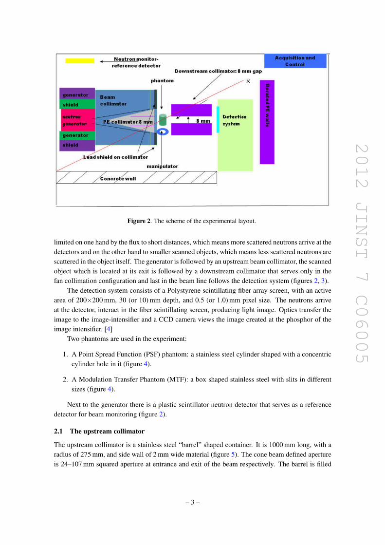
2012 JINST 7 C06005
Figure 2 The scheme of the experimental layout
limited on one hand by the flux to short distances which means more scattered neutrons arrive at thedetectors and on the other hand to smaller scanned objects which means less scattered neutrons arescattered in the object itself The generator is followed by an upstream beam collimator the scannedobject which is located at its exit is followed by a downstream collimator that serves only in thefan collimation configuration and last in the beam line follows the detection system (figures 2 3)
The detection system consists of a Polystyrene scintillating fiber array screen with an activearea of 200times200 mm 30 (or 10) mm depth and 05 (or 10) mm pixel size The neutrons arriveat the detector interact in the fiber scintillating screen producing light image Optics transfer theimage to the image-intensifier and a CCD camera views the image created at the phosphor of theimage intensifier [4]
Two phantoms are used in the experiment
1 A Point Spread Function (PSF) phantom a stainless steel cylinder shaped with a concentriccylinder hole in it (figure 4)
2 A Modulation Transfer Phantom (MTF) a box shaped stainless steel with slits in differentsizes (figure 4)
Next to the generator there is a plastic scintillator neutron detector that serves as a referencedetector for beam monitoring (figure 2)
21 The upstream collimator
The upstream collimator is a stainless steel ldquobarrelrdquo shaped container It is 1000 mm long with aradius of 275 mm and side wall of 2 mm wide material (figure 5) The cone beam defined apertureis 24ndash107 mm squared aperture at entrance and exit of the beam respectively The barrel is filled
ndash 3 ndash
2012 JINST 7 C06005
Figure 3 A picture of the experiment
Figure 4 The PSF stainless steel phantom (left) the MTF stainless steel phantom (right)
with one of the three different moderating materials examined The results for the three differentmoderating materials are compared as part of the optimization studies
In order to define the fan beam configuration a fan beam definer made of 5 borated polyethy-lene is put into the cone hole Once it is in the hole it defines a horizontal fan beam of 8 mm gapThe width of the fan beam gap was optimized in order to get maximum SNR and contrast
ndash 4 ndash
2012 JINST 7 C06005
Figure 5 The upstream collimator Illustrations of the cone beam collimator fan beam definer and fan beamcollimator
Figure 6 The downstream collimator
22 The downstream collimator
The downstream collimator (figure 6) serves mostly in the fan configuration It is a 600 mm long320times280 mm2 5 borated polyethylene collimator with a 8 mm gap It is located 150 mm down-stream of the phantom 150 mm upstream of the detector
3 Experimental Results
31 Scatter from the scanned object
The scatter effect was checked in cone configuration in several consecutive experiments in order toverify that we actually deal with scatter although the object under examination is not large
ndash 5 ndash
2012 JINST 7 C06005
Figure 7 The PSF images ldquonearrdquo (upper left image) and ldquofarrdquo (lower left image) from the detector ThePSF image profiles are shown along with enlarged relevant parts of the images respectively (right images)
Table 1 The calculated contrasts for the different phantom thicknesses with and without the addition of anattached scatterer to the phantom
Thickness ofStainless steel inMTF phantom
Contrastwithoutscatterer
Contrast withscatterer
12 cm 03plusmn1 023plusmn122 cm 022plusmn1 016plusmn1
The influence of the phantom location in respect to the detector on the image contrast ischecked (figure 7) A PSF phantom is positioned either in close proximity to the detector (ldquonearrdquo)or at the exit of the beam collimator the profile (ldquofarrdquo) The images are normalized and analyzedand the contrast (eq (31)) is then calculated from the image profiles
Contrast =Iminus Ibg
Ibg(31)
The resulted contrast when the PSF phantom is located ldquonearrdquo the detector is 048plusmn04 and whenthe PSF phantom is located ldquofarrdquo the contrast is 058plusmn04 The nearer the phantom to the detectorthe contrast lowers as a result of more scattered particles arriving at the detector ( in spite of a rise inthe geometrical un-sharpness that lowers the contrast as the phantom gets further from the detector)
The effect of scatter on the contrast is further studied from images of the MTF phantom whichwas located at the detector with and without a scatterer attached to it (figure 8) The scatterer whichis used is a Polyethylene brick The resulted contrasts are summarized in table 1
From figure 9 it can be clearly seen that the contrast is deteriorated with the attachment of thescatterer to the phantom as a result of more scattered neutrons arriving at the detector Calculations
ndash 6 ndash
2012 JINST 7 C06005
Figure 8 The MTF phantom with and without attached PE scatterer and the resulted images The redrectangles define the profiles studied
Figure 9 The profiles of the thick (22 cm) part of the MTF and thin (12 cm) of the MTF phantom with(two lower curves) and without (two upper curves) the PE scatterer attached to the MTF phantom
along the profiles show deterioration of about 15 The effects of scatterer location and size onthe scatter contribution are also studied by using a set of 6 cm wide Iron boards which are locatedalong the beam line in different distances from the detector each time as can be seen in figure 10
As the scatterer width enlarges the signal is lowered due to more attenuation but the contrastis lowered due to more scatter (figure 12) As the scatterer gets closer to the detector (figure 11nearD) the signal is larger and the contrast lowers The contrast is the highest when the scatterer isthe furthest from the detector at the exit of the beam collimator (figure 11 nearC)
ndash 7 ndash
2012 JINST 7 C06005
Figure 10 The experimental layout for Iron scatterer location and size influence on the image quality study
Figure 11 The profiles of the MTF Phantom image for different locations (mid-middle of beam line nearCmdash near the beam collimator nearD mdash near the detector) of scatterer in the beam line
The results from the above experiments show we can rely on the measurement of contrast asindicator for scatter contribution in the layout of our setup
32 Lowering the scatter from the surroundings
One of the largest scatter contributions in the experiment comes from the neutrons scattered fromthe surroundings Due to the 4π nature of our neutron source and the fact that the experimenttakes place in a sealed hall we expect background neutrons to arrive at the detector Several at-tempts were made to lower the scatter from which the most fruitful was enlarging the shielding ofthe neutron source which raised the SNR in the air profiles of the fan beam configuration from 41to 751 to 91 in consecutive experiments in which a layer of 78 cm wide borated PE was addedeach time to shield the generator As a consequence a massive generator shield was designed onthe basis of former works [5] and related calculations The generator shield was made of 10 cm
ndash 8 ndash
2012 JINST 7 C06005
Figure 12 The profiles of the MTF Phantom image for different scatterer sizes in the same location (middleof beam line) in the beam line
wide iron serving as the inelastic scatterer around the generator tube surrounded by a 50 cm wideborated polyethylene rich material in H and B with high affinity to capture the already ldquosloweddownrdquo neutrons followed by a 5 cm lead shield in order to ldquocatchrdquo the gammas that emerge fromthe reactions between the boron and hydrogen and the incoming neutrons The contrasts in coneand fan configurationsrsquo images were compared between the setup before and after using the mas-sive shield (figure 13) The Contrast is better using the massive generator shield The Contrast isbetter in fan than in cone configuration (both massive shield setup)
33 Optimization of the moderating material
The beam collimator was optimized in respect to the moderating material within the barrelFor simplicity and ease of use three different materials were used water Borax
(Na2B4O7middot10H2O) ρ=173 grcm3 and Borax and water mixture (Na2B4O7middot14H2O) ρ = 209grcm3 Three consecutive experiments were carried out with the different moderating materials
The beam was monitored using the reference detector (figure 14) and the results were normal-ized accordingly
Figures 15ndash19 show the resulted images and related graphs of the experiments Table 2 sum-marizes the calculated contrasts and SNR values from the resulted images
In figure 17 it can be seen that the signal for the Borax and water mixture derived from thecone air images (figure 16) is the lowest of the three moderating materials indicating less scatteredparticles arriving at the detector and contributing to the signal
In figure 18 it can be seen that the contrast in the cone configuration for the PSF image is bestfor the Borax and water mixture moderating material In figure 19 the SNR is the highest for theBorax and water mixture as a moderating material in the images of the fan beam configuration air
ndash 9 ndash
2012 JINST 7 C06005
Figure 13 PSF profiles with fan (blue) and cone (fuchsia) configuration for the massive shield for cone(yellow) configuration without the massive shield
Figure 14 The beam (signal) as a function of time measured by the beam reference detector
images Both indications show that the scattered contribution that influence both IQ parameters(contrast and SNR) is lower when using a Borax and water mixture as the moderating materialwithin the beam collimator
ndash 10 ndash
2012 JINST 7 C06005
Figure 15 The PSF resulted images and their relative profiles (below each) for cone configuration (left) fanconfiguration (mid) The right image is the fan configuration air image
Figure 16 The cone configuration air image and its resulted profile
Table 2 The contrasts and SNR values for the three different moderating materials for the two beam con-figurations
Moderating materialsFAN Config CONE configSNRminus1(air profiles) Contrast PSF Contrast PSF
BORAX 011plusmn1 097plusmn1 079plusmn1BampW 0017plusmn1 098plusmn1 088plusmn1Water 0088plusmn1 089plusmn1 081plusmn1
In the analysis of the water and Borax moderating materials a slight preference for the Boraxover the water is seen in all IQ aspects as a moderating material
The resulted contrasts and SNR values are summarized in table 2 It is clearly seen that theBorax and water mixture as the moderating material in the beam collimator gives the best IQ resultsThe contrasts values are better for fan configuration than those for cone configuration for all themoderating materials Comparing the results of the Borax and Water moderating materials onecan see that there is a slight advantage to the Borax on water
ndash 11 ndash
2012 JINST 7 C06005
Figure 17 The air image profile for the cone configuration for the three moderating materials The tableshows the averaged differences ratios for the three(B-Borax W-water BampW-Boraxampwater)
Figure 18 The PSF profile for the 3 different moderating materials for cone configuration
ndash 12 ndash
2012 JINST 7 C06005
Figure 19 The profiles of the air images in fan configuration for the different moderating materials
Table 3 Simulation contrast results
Moderating materialsFAN Configuration CONE configurationContrast PSF Contrast PSF
BORAX 083plusmn10 064 plusmn10BampW 091 plusmn10 070plusmn10Water 083 plusmn10 064plusmn10
4 Simulation results
As part of our study the experimental setup was imbedded into GEANT4 and optimized runs werecarried out in different manners A comparison between the three different moderating materialsBorax Borax amp water mixture and water in both fan and cone configurations was made by asimulation of the PSF phantom Figures 20 21 show the profiles of the phantom simulation resultsfor the cone and fan configurations with the three different moderating materials The graphs showthe energy deposited in each fiber in the detector for all the cases
The contrasts were calculated for the simulated PSF phantom within the geometry of the ex-periment as stated above The results are shown in table 3 where it can be seen that the contrastsare always better as expected in the fan configuration The contrasts are best for Borax and watermixture and rather similar for Borax and water for both configurations
In the analysis of the simulationsrsquo results we observed the different components of the energydeposited in the imaging detector The ratios of the direct and scatter radiation contributions andthe total radiation energies for the fan and cone beam configurations were calculated The resultedgraphs and ratios for the direct neutrons component are shown in table 4 and figures 22 23 for thethree different moderating materials It can be observed that the contribution of the direct neutron
ndash 13 ndash
2012 JINST 7 C06005
Figure 20 The phantom profiles for the cone beam configuration for three different moderating materialsBorax Borax amp water mixture and water
Figure 21 The phantom profiles for the fan beam configuration for three different moderating materialsBorax Borax amp water mixture and water
radiation is always larger in the fan configuration in comparison to the cone configuration Forboth configurations the Borax amp water solution gives the highest ratio of direct radiation to totalradiation from the three examined moderating materials
ndash 14 ndash
2012 JINST 7 C06005
Table 4 The average ratios of the direct neutrons radiation energy contribution and the total detected radia-tion energy are shown for the fan and cone configurations for the three different moderating materials
Moderating materialsFAN Configura-tion
CONE configura-tion
DirectRadiation energy contribution []
BORAX 961plusmn17 895plusmn29BampW 970plusmn17 903plusmn27Water 942plusmn20 882plusmn29
Figure 22 The ratios of the direct neutrons radiation contribution and the total radiation detected in eachfiber for the fan configuration and for the three different moderating materials
5 Conclusions
The usage of the Borax and water mixture solution as the moderating material gives the best IQfrom the three different moderating materials which are studied The IQ measures are the SNRand the contrasts in the image The experimental results are consistent with the related simulationThe superiority of the Borax and water solution is for both configurations however comparing theconfigurations for each of the moderating materials we find better IQ for the fan configuration asexpected
ndash 15 ndash
2012 JINST 7 C06005
Figure 23 The ratios of the direct neutrons radiation contribution and the total radiation detected in eachfiber for the cone configuration and for the three different moderating materials
The surroundingsrsquo scatter is reduced meaningfully using a dedicated massive generator shieldwhich was built based on experimental and simulation studies and tested successfully for provenefficiency
As a consequence a dedicated collimator for a D-T generator 142 MeV Fast Neutrons isdeveloped for imaging purposes using the massive generator shield and the Borax and watermixture as the moderating material
References
[1] I Sabo-Napadensky and O Amir Reduction of scattering artifact in multislice CT MJ Flynn edProc SPIE 5745 (2005) 983
[2] J Star-Lack et al Efficient scatter correction using asymmetric kernels Proc SPIE 7258 (2009)72581Z
[3] BR Grogan The development of a parameterized scatter removal algorithm for nuclear materialsidentification system imaging PhD dissertation University of Tennessee Knoxville USA (2010)
[4] I Mor et al High spatial resolution fast-neutron imaging detectors for pulsed fast-neutrontransmission spectroscopy 2009 JINST 4 P05016
[5] American National Standards Institute Neutron radiation protection shielding mdash design principles andconsiderations for the choice of appropriate materials ISO 141522001 ANSI USA (2007)
ndash 16 ndash
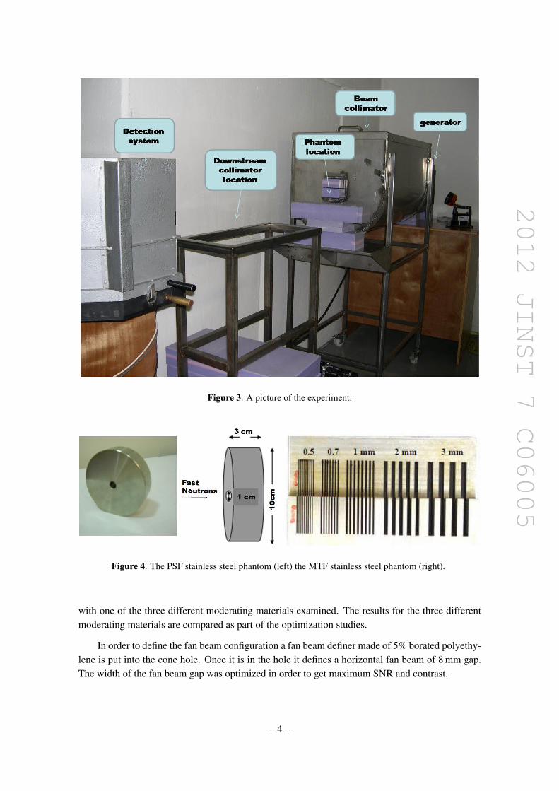
2012 JINST 7 C06005
Figure 3 A picture of the experiment
Figure 4 The PSF stainless steel phantom (left) the MTF stainless steel phantom (right)
with one of the three different moderating materials examined The results for the three differentmoderating materials are compared as part of the optimization studies
In order to define the fan beam configuration a fan beam definer made of 5 borated polyethy-lene is put into the cone hole Once it is in the hole it defines a horizontal fan beam of 8 mm gapThe width of the fan beam gap was optimized in order to get maximum SNR and contrast
ndash 4 ndash
2012 JINST 7 C06005
Figure 5 The upstream collimator Illustrations of the cone beam collimator fan beam definer and fan beamcollimator
Figure 6 The downstream collimator
22 The downstream collimator
The downstream collimator (figure 6) serves mostly in the fan configuration It is a 600 mm long320times280 mm2 5 borated polyethylene collimator with a 8 mm gap It is located 150 mm down-stream of the phantom 150 mm upstream of the detector
3 Experimental Results
31 Scatter from the scanned object
The scatter effect was checked in cone configuration in several consecutive experiments in order toverify that we actually deal with scatter although the object under examination is not large
ndash 5 ndash
2012 JINST 7 C06005
Figure 7 The PSF images ldquonearrdquo (upper left image) and ldquofarrdquo (lower left image) from the detector ThePSF image profiles are shown along with enlarged relevant parts of the images respectively (right images)
Table 1 The calculated contrasts for the different phantom thicknesses with and without the addition of anattached scatterer to the phantom
Thickness ofStainless steel inMTF phantom
Contrastwithoutscatterer
Contrast withscatterer
12 cm 03plusmn1 023plusmn122 cm 022plusmn1 016plusmn1
The influence of the phantom location in respect to the detector on the image contrast ischecked (figure 7) A PSF phantom is positioned either in close proximity to the detector (ldquonearrdquo)or at the exit of the beam collimator the profile (ldquofarrdquo) The images are normalized and analyzedand the contrast (eq (31)) is then calculated from the image profiles
Contrast =Iminus Ibg
Ibg(31)
The resulted contrast when the PSF phantom is located ldquonearrdquo the detector is 048plusmn04 and whenthe PSF phantom is located ldquofarrdquo the contrast is 058plusmn04 The nearer the phantom to the detectorthe contrast lowers as a result of more scattered particles arriving at the detector ( in spite of a rise inthe geometrical un-sharpness that lowers the contrast as the phantom gets further from the detector)
The effect of scatter on the contrast is further studied from images of the MTF phantom whichwas located at the detector with and without a scatterer attached to it (figure 8) The scatterer whichis used is a Polyethylene brick The resulted contrasts are summarized in table 1
From figure 9 it can be clearly seen that the contrast is deteriorated with the attachment of thescatterer to the phantom as a result of more scattered neutrons arriving at the detector Calculations
ndash 6 ndash
2012 JINST 7 C06005
Figure 8 The MTF phantom with and without attached PE scatterer and the resulted images The redrectangles define the profiles studied
Figure 9 The profiles of the thick (22 cm) part of the MTF and thin (12 cm) of the MTF phantom with(two lower curves) and without (two upper curves) the PE scatterer attached to the MTF phantom
along the profiles show deterioration of about 15 The effects of scatterer location and size onthe scatter contribution are also studied by using a set of 6 cm wide Iron boards which are locatedalong the beam line in different distances from the detector each time as can be seen in figure 10
As the scatterer width enlarges the signal is lowered due to more attenuation but the contrastis lowered due to more scatter (figure 12) As the scatterer gets closer to the detector (figure 11nearD) the signal is larger and the contrast lowers The contrast is the highest when the scatterer isthe furthest from the detector at the exit of the beam collimator (figure 11 nearC)
ndash 7 ndash
2012 JINST 7 C06005
Figure 10 The experimental layout for Iron scatterer location and size influence on the image quality study
Figure 11 The profiles of the MTF Phantom image for different locations (mid-middle of beam line nearCmdash near the beam collimator nearD mdash near the detector) of scatterer in the beam line
The results from the above experiments show we can rely on the measurement of contrast asindicator for scatter contribution in the layout of our setup
32 Lowering the scatter from the surroundings
One of the largest scatter contributions in the experiment comes from the neutrons scattered fromthe surroundings Due to the 4π nature of our neutron source and the fact that the experimenttakes place in a sealed hall we expect background neutrons to arrive at the detector Several at-tempts were made to lower the scatter from which the most fruitful was enlarging the shielding ofthe neutron source which raised the SNR in the air profiles of the fan beam configuration from 41to 751 to 91 in consecutive experiments in which a layer of 78 cm wide borated PE was addedeach time to shield the generator As a consequence a massive generator shield was designed onthe basis of former works [5] and related calculations The generator shield was made of 10 cm
ndash 8 ndash
2012 JINST 7 C06005
Figure 12 The profiles of the MTF Phantom image for different scatterer sizes in the same location (middleof beam line) in the beam line
wide iron serving as the inelastic scatterer around the generator tube surrounded by a 50 cm wideborated polyethylene rich material in H and B with high affinity to capture the already ldquosloweddownrdquo neutrons followed by a 5 cm lead shield in order to ldquocatchrdquo the gammas that emerge fromthe reactions between the boron and hydrogen and the incoming neutrons The contrasts in coneand fan configurationsrsquo images were compared between the setup before and after using the mas-sive shield (figure 13) The Contrast is better using the massive generator shield The Contrast isbetter in fan than in cone configuration (both massive shield setup)
33 Optimization of the moderating material
The beam collimator was optimized in respect to the moderating material within the barrelFor simplicity and ease of use three different materials were used water Borax
(Na2B4O7middot10H2O) ρ=173 grcm3 and Borax and water mixture (Na2B4O7middot14H2O) ρ = 209grcm3 Three consecutive experiments were carried out with the different moderating materials
The beam was monitored using the reference detector (figure 14) and the results were normal-ized accordingly
Figures 15ndash19 show the resulted images and related graphs of the experiments Table 2 sum-marizes the calculated contrasts and SNR values from the resulted images
In figure 17 it can be seen that the signal for the Borax and water mixture derived from thecone air images (figure 16) is the lowest of the three moderating materials indicating less scatteredparticles arriving at the detector and contributing to the signal
In figure 18 it can be seen that the contrast in the cone configuration for the PSF image is bestfor the Borax and water mixture moderating material In figure 19 the SNR is the highest for theBorax and water mixture as a moderating material in the images of the fan beam configuration air
ndash 9 ndash
2012 JINST 7 C06005
Figure 13 PSF profiles with fan (blue) and cone (fuchsia) configuration for the massive shield for cone(yellow) configuration without the massive shield
Figure 14 The beam (signal) as a function of time measured by the beam reference detector
images Both indications show that the scattered contribution that influence both IQ parameters(contrast and SNR) is lower when using a Borax and water mixture as the moderating materialwithin the beam collimator
ndash 10 ndash
2012 JINST 7 C06005
Figure 15 The PSF resulted images and their relative profiles (below each) for cone configuration (left) fanconfiguration (mid) The right image is the fan configuration air image
Figure 16 The cone configuration air image and its resulted profile
Table 2 The contrasts and SNR values for the three different moderating materials for the two beam con-figurations
Moderating materialsFAN Config CONE configSNRminus1(air profiles) Contrast PSF Contrast PSF
BORAX 011plusmn1 097plusmn1 079plusmn1BampW 0017plusmn1 098plusmn1 088plusmn1Water 0088plusmn1 089plusmn1 081plusmn1
In the analysis of the water and Borax moderating materials a slight preference for the Boraxover the water is seen in all IQ aspects as a moderating material
The resulted contrasts and SNR values are summarized in table 2 It is clearly seen that theBorax and water mixture as the moderating material in the beam collimator gives the best IQ resultsThe contrasts values are better for fan configuration than those for cone configuration for all themoderating materials Comparing the results of the Borax and Water moderating materials onecan see that there is a slight advantage to the Borax on water
ndash 11 ndash
2012 JINST 7 C06005
Figure 17 The air image profile for the cone configuration for the three moderating materials The tableshows the averaged differences ratios for the three(B-Borax W-water BampW-Boraxampwater)
Figure 18 The PSF profile for the 3 different moderating materials for cone configuration
ndash 12 ndash
2012 JINST 7 C06005
Figure 19 The profiles of the air images in fan configuration for the different moderating materials
Table 3 Simulation contrast results
Moderating materialsFAN Configuration CONE configurationContrast PSF Contrast PSF
BORAX 083plusmn10 064 plusmn10BampW 091 plusmn10 070plusmn10Water 083 plusmn10 064plusmn10
4 Simulation results
As part of our study the experimental setup was imbedded into GEANT4 and optimized runs werecarried out in different manners A comparison between the three different moderating materialsBorax Borax amp water mixture and water in both fan and cone configurations was made by asimulation of the PSF phantom Figures 20 21 show the profiles of the phantom simulation resultsfor the cone and fan configurations with the three different moderating materials The graphs showthe energy deposited in each fiber in the detector for all the cases
The contrasts were calculated for the simulated PSF phantom within the geometry of the ex-periment as stated above The results are shown in table 3 where it can be seen that the contrastsare always better as expected in the fan configuration The contrasts are best for Borax and watermixture and rather similar for Borax and water for both configurations
In the analysis of the simulationsrsquo results we observed the different components of the energydeposited in the imaging detector The ratios of the direct and scatter radiation contributions andthe total radiation energies for the fan and cone beam configurations were calculated The resultedgraphs and ratios for the direct neutrons component are shown in table 4 and figures 22 23 for thethree different moderating materials It can be observed that the contribution of the direct neutron
ndash 13 ndash
2012 JINST 7 C06005
Figure 20 The phantom profiles for the cone beam configuration for three different moderating materialsBorax Borax amp water mixture and water
Figure 21 The phantom profiles for the fan beam configuration for three different moderating materialsBorax Borax amp water mixture and water
radiation is always larger in the fan configuration in comparison to the cone configuration Forboth configurations the Borax amp water solution gives the highest ratio of direct radiation to totalradiation from the three examined moderating materials
ndash 14 ndash
2012 JINST 7 C06005
Table 4 The average ratios of the direct neutrons radiation energy contribution and the total detected radia-tion energy are shown for the fan and cone configurations for the three different moderating materials
Moderating materialsFAN Configura-tion
CONE configura-tion
DirectRadiation energy contribution []
BORAX 961plusmn17 895plusmn29BampW 970plusmn17 903plusmn27Water 942plusmn20 882plusmn29
Figure 22 The ratios of the direct neutrons radiation contribution and the total radiation detected in eachfiber for the fan configuration and for the three different moderating materials
5 Conclusions
The usage of the Borax and water mixture solution as the moderating material gives the best IQfrom the three different moderating materials which are studied The IQ measures are the SNRand the contrasts in the image The experimental results are consistent with the related simulationThe superiority of the Borax and water solution is for both configurations however comparing theconfigurations for each of the moderating materials we find better IQ for the fan configuration asexpected
ndash 15 ndash
2012 JINST 7 C06005
Figure 23 The ratios of the direct neutrons radiation contribution and the total radiation detected in eachfiber for the cone configuration and for the three different moderating materials
The surroundingsrsquo scatter is reduced meaningfully using a dedicated massive generator shieldwhich was built based on experimental and simulation studies and tested successfully for provenefficiency
As a consequence a dedicated collimator for a D-T generator 142 MeV Fast Neutrons isdeveloped for imaging purposes using the massive generator shield and the Borax and watermixture as the moderating material
References
[1] I Sabo-Napadensky and O Amir Reduction of scattering artifact in multislice CT MJ Flynn edProc SPIE 5745 (2005) 983
[2] J Star-Lack et al Efficient scatter correction using asymmetric kernels Proc SPIE 7258 (2009)72581Z
[3] BR Grogan The development of a parameterized scatter removal algorithm for nuclear materialsidentification system imaging PhD dissertation University of Tennessee Knoxville USA (2010)
[4] I Mor et al High spatial resolution fast-neutron imaging detectors for pulsed fast-neutrontransmission spectroscopy 2009 JINST 4 P05016
[5] American National Standards Institute Neutron radiation protection shielding mdash design principles andconsiderations for the choice of appropriate materials ISO 141522001 ANSI USA (2007)
ndash 16 ndash
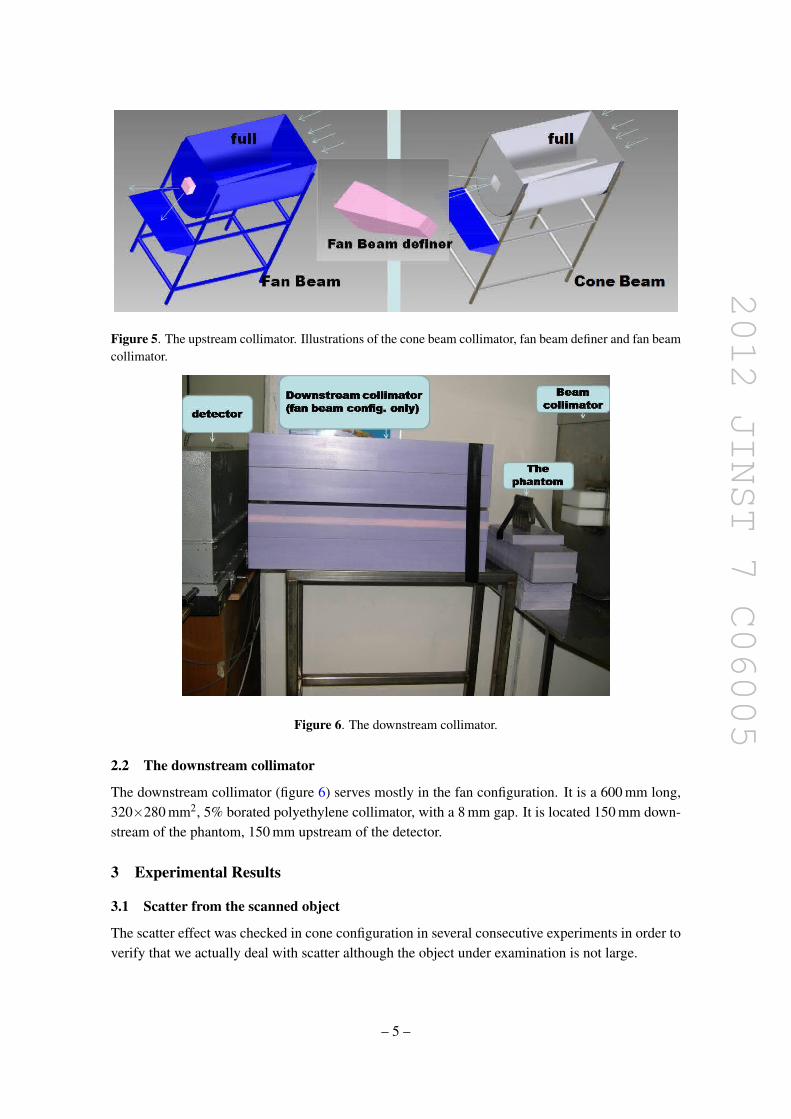
2012 JINST 7 C06005
Figure 5 The upstream collimator Illustrations of the cone beam collimator fan beam definer and fan beamcollimator
Figure 6 The downstream collimator
22 The downstream collimator
The downstream collimator (figure 6) serves mostly in the fan configuration It is a 600 mm long320times280 mm2 5 borated polyethylene collimator with a 8 mm gap It is located 150 mm down-stream of the phantom 150 mm upstream of the detector
3 Experimental Results
31 Scatter from the scanned object
The scatter effect was checked in cone configuration in several consecutive experiments in order toverify that we actually deal with scatter although the object under examination is not large
ndash 5 ndash
2012 JINST 7 C06005
Figure 7 The PSF images ldquonearrdquo (upper left image) and ldquofarrdquo (lower left image) from the detector ThePSF image profiles are shown along with enlarged relevant parts of the images respectively (right images)
Table 1 The calculated contrasts for the different phantom thicknesses with and without the addition of anattached scatterer to the phantom
Thickness ofStainless steel inMTF phantom
Contrastwithoutscatterer
Contrast withscatterer
12 cm 03plusmn1 023plusmn122 cm 022plusmn1 016plusmn1
The influence of the phantom location in respect to the detector on the image contrast ischecked (figure 7) A PSF phantom is positioned either in close proximity to the detector (ldquonearrdquo)or at the exit of the beam collimator the profile (ldquofarrdquo) The images are normalized and analyzedand the contrast (eq (31)) is then calculated from the image profiles
Contrast =Iminus Ibg
Ibg(31)
The resulted contrast when the PSF phantom is located ldquonearrdquo the detector is 048plusmn04 and whenthe PSF phantom is located ldquofarrdquo the contrast is 058plusmn04 The nearer the phantom to the detectorthe contrast lowers as a result of more scattered particles arriving at the detector ( in spite of a rise inthe geometrical un-sharpness that lowers the contrast as the phantom gets further from the detector)
The effect of scatter on the contrast is further studied from images of the MTF phantom whichwas located at the detector with and without a scatterer attached to it (figure 8) The scatterer whichis used is a Polyethylene brick The resulted contrasts are summarized in table 1
From figure 9 it can be clearly seen that the contrast is deteriorated with the attachment of thescatterer to the phantom as a result of more scattered neutrons arriving at the detector Calculations
ndash 6 ndash
2012 JINST 7 C06005
Figure 8 The MTF phantom with and without attached PE scatterer and the resulted images The redrectangles define the profiles studied
Figure 9 The profiles of the thick (22 cm) part of the MTF and thin (12 cm) of the MTF phantom with(two lower curves) and without (two upper curves) the PE scatterer attached to the MTF phantom
along the profiles show deterioration of about 15 The effects of scatterer location and size onthe scatter contribution are also studied by using a set of 6 cm wide Iron boards which are locatedalong the beam line in different distances from the detector each time as can be seen in figure 10
As the scatterer width enlarges the signal is lowered due to more attenuation but the contrastis lowered due to more scatter (figure 12) As the scatterer gets closer to the detector (figure 11nearD) the signal is larger and the contrast lowers The contrast is the highest when the scatterer isthe furthest from the detector at the exit of the beam collimator (figure 11 nearC)
ndash 7 ndash
2012 JINST 7 C06005
Figure 10 The experimental layout for Iron scatterer location and size influence on the image quality study
Figure 11 The profiles of the MTF Phantom image for different locations (mid-middle of beam line nearCmdash near the beam collimator nearD mdash near the detector) of scatterer in the beam line
The results from the above experiments show we can rely on the measurement of contrast asindicator for scatter contribution in the layout of our setup
32 Lowering the scatter from the surroundings
One of the largest scatter contributions in the experiment comes from the neutrons scattered fromthe surroundings Due to the 4π nature of our neutron source and the fact that the experimenttakes place in a sealed hall we expect background neutrons to arrive at the detector Several at-tempts were made to lower the scatter from which the most fruitful was enlarging the shielding ofthe neutron source which raised the SNR in the air profiles of the fan beam configuration from 41to 751 to 91 in consecutive experiments in which a layer of 78 cm wide borated PE was addedeach time to shield the generator As a consequence a massive generator shield was designed onthe basis of former works [5] and related calculations The generator shield was made of 10 cm
ndash 8 ndash
2012 JINST 7 C06005
Figure 12 The profiles of the MTF Phantom image for different scatterer sizes in the same location (middleof beam line) in the beam line
wide iron serving as the inelastic scatterer around the generator tube surrounded by a 50 cm wideborated polyethylene rich material in H and B with high affinity to capture the already ldquosloweddownrdquo neutrons followed by a 5 cm lead shield in order to ldquocatchrdquo the gammas that emerge fromthe reactions between the boron and hydrogen and the incoming neutrons The contrasts in coneand fan configurationsrsquo images were compared between the setup before and after using the mas-sive shield (figure 13) The Contrast is better using the massive generator shield The Contrast isbetter in fan than in cone configuration (both massive shield setup)
33 Optimization of the moderating material
The beam collimator was optimized in respect to the moderating material within the barrelFor simplicity and ease of use three different materials were used water Borax
(Na2B4O7middot10H2O) ρ=173 grcm3 and Borax and water mixture (Na2B4O7middot14H2O) ρ = 209grcm3 Three consecutive experiments were carried out with the different moderating materials
The beam was monitored using the reference detector (figure 14) and the results were normal-ized accordingly
Figures 15ndash19 show the resulted images and related graphs of the experiments Table 2 sum-marizes the calculated contrasts and SNR values from the resulted images
In figure 17 it can be seen that the signal for the Borax and water mixture derived from thecone air images (figure 16) is the lowest of the three moderating materials indicating less scatteredparticles arriving at the detector and contributing to the signal
In figure 18 it can be seen that the contrast in the cone configuration for the PSF image is bestfor the Borax and water mixture moderating material In figure 19 the SNR is the highest for theBorax and water mixture as a moderating material in the images of the fan beam configuration air
ndash 9 ndash
2012 JINST 7 C06005
Figure 13 PSF profiles with fan (blue) and cone (fuchsia) configuration for the massive shield for cone(yellow) configuration without the massive shield
Figure 14 The beam (signal) as a function of time measured by the beam reference detector
images Both indications show that the scattered contribution that influence both IQ parameters(contrast and SNR) is lower when using a Borax and water mixture as the moderating materialwithin the beam collimator
ndash 10 ndash
2012 JINST 7 C06005
Figure 15 The PSF resulted images and their relative profiles (below each) for cone configuration (left) fanconfiguration (mid) The right image is the fan configuration air image
Figure 16 The cone configuration air image and its resulted profile
Table 2 The contrasts and SNR values for the three different moderating materials for the two beam con-figurations
Moderating materialsFAN Config CONE configSNRminus1(air profiles) Contrast PSF Contrast PSF
BORAX 011plusmn1 097plusmn1 079plusmn1BampW 0017plusmn1 098plusmn1 088plusmn1Water 0088plusmn1 089plusmn1 081plusmn1
In the analysis of the water and Borax moderating materials a slight preference for the Boraxover the water is seen in all IQ aspects as a moderating material
The resulted contrasts and SNR values are summarized in table 2 It is clearly seen that theBorax and water mixture as the moderating material in the beam collimator gives the best IQ resultsThe contrasts values are better for fan configuration than those for cone configuration for all themoderating materials Comparing the results of the Borax and Water moderating materials onecan see that there is a slight advantage to the Borax on water
ndash 11 ndash
2012 JINST 7 C06005
Figure 17 The air image profile for the cone configuration for the three moderating materials The tableshows the averaged differences ratios for the three(B-Borax W-water BampW-Boraxampwater)
Figure 18 The PSF profile for the 3 different moderating materials for cone configuration
ndash 12 ndash
2012 JINST 7 C06005
Figure 19 The profiles of the air images in fan configuration for the different moderating materials
Table 3 Simulation contrast results
Moderating materialsFAN Configuration CONE configurationContrast PSF Contrast PSF
BORAX 083plusmn10 064 plusmn10BampW 091 plusmn10 070plusmn10Water 083 plusmn10 064plusmn10
4 Simulation results
As part of our study the experimental setup was imbedded into GEANT4 and optimized runs werecarried out in different manners A comparison between the three different moderating materialsBorax Borax amp water mixture and water in both fan and cone configurations was made by asimulation of the PSF phantom Figures 20 21 show the profiles of the phantom simulation resultsfor the cone and fan configurations with the three different moderating materials The graphs showthe energy deposited in each fiber in the detector for all the cases
The contrasts were calculated for the simulated PSF phantom within the geometry of the ex-periment as stated above The results are shown in table 3 where it can be seen that the contrastsare always better as expected in the fan configuration The contrasts are best for Borax and watermixture and rather similar for Borax and water for both configurations
In the analysis of the simulationsrsquo results we observed the different components of the energydeposited in the imaging detector The ratios of the direct and scatter radiation contributions andthe total radiation energies for the fan and cone beam configurations were calculated The resultedgraphs and ratios for the direct neutrons component are shown in table 4 and figures 22 23 for thethree different moderating materials It can be observed that the contribution of the direct neutron
ndash 13 ndash
2012 JINST 7 C06005
Figure 20 The phantom profiles for the cone beam configuration for three different moderating materialsBorax Borax amp water mixture and water
Figure 21 The phantom profiles for the fan beam configuration for three different moderating materialsBorax Borax amp water mixture and water
radiation is always larger in the fan configuration in comparison to the cone configuration Forboth configurations the Borax amp water solution gives the highest ratio of direct radiation to totalradiation from the three examined moderating materials
ndash 14 ndash
2012 JINST 7 C06005
Table 4 The average ratios of the direct neutrons radiation energy contribution and the total detected radia-tion energy are shown for the fan and cone configurations for the three different moderating materials
Moderating materialsFAN Configura-tion
CONE configura-tion
DirectRadiation energy contribution []
BORAX 961plusmn17 895plusmn29BampW 970plusmn17 903plusmn27Water 942plusmn20 882plusmn29
Figure 22 The ratios of the direct neutrons radiation contribution and the total radiation detected in eachfiber for the fan configuration and for the three different moderating materials
5 Conclusions
The usage of the Borax and water mixture solution as the moderating material gives the best IQfrom the three different moderating materials which are studied The IQ measures are the SNRand the contrasts in the image The experimental results are consistent with the related simulationThe superiority of the Borax and water solution is for both configurations however comparing theconfigurations for each of the moderating materials we find better IQ for the fan configuration asexpected
ndash 15 ndash
2012 JINST 7 C06005
Figure 23 The ratios of the direct neutrons radiation contribution and the total radiation detected in eachfiber for the cone configuration and for the three different moderating materials
The surroundingsrsquo scatter is reduced meaningfully using a dedicated massive generator shieldwhich was built based on experimental and simulation studies and tested successfully for provenefficiency
As a consequence a dedicated collimator for a D-T generator 142 MeV Fast Neutrons isdeveloped for imaging purposes using the massive generator shield and the Borax and watermixture as the moderating material
References
[1] I Sabo-Napadensky and O Amir Reduction of scattering artifact in multislice CT MJ Flynn edProc SPIE 5745 (2005) 983
[2] J Star-Lack et al Efficient scatter correction using asymmetric kernels Proc SPIE 7258 (2009)72581Z
[3] BR Grogan The development of a parameterized scatter removal algorithm for nuclear materialsidentification system imaging PhD dissertation University of Tennessee Knoxville USA (2010)
[4] I Mor et al High spatial resolution fast-neutron imaging detectors for pulsed fast-neutrontransmission spectroscopy 2009 JINST 4 P05016
[5] American National Standards Institute Neutron radiation protection shielding mdash design principles andconsiderations for the choice of appropriate materials ISO 141522001 ANSI USA (2007)
ndash 16 ndash
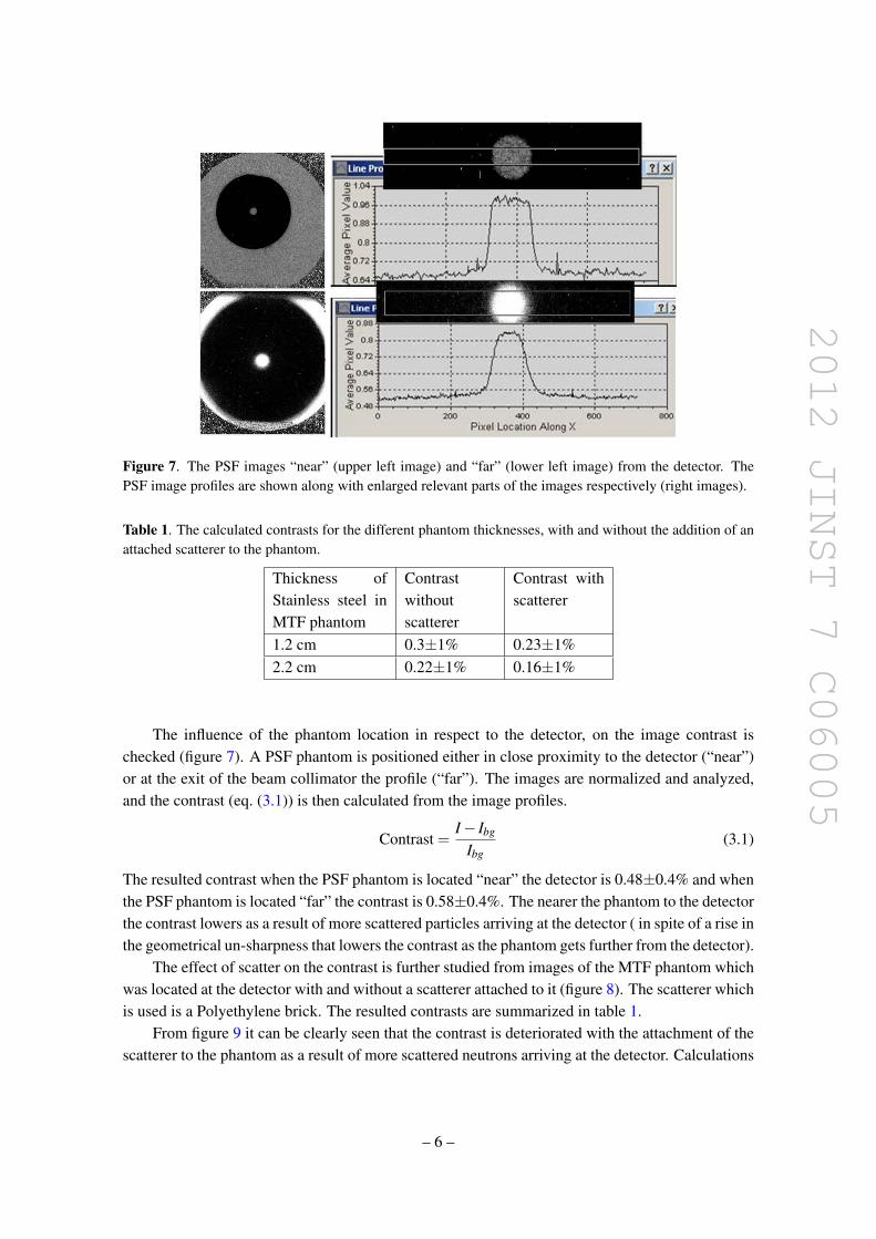
2012 JINST 7 C06005
Figure 7 The PSF images ldquonearrdquo (upper left image) and ldquofarrdquo (lower left image) from the detector ThePSF image profiles are shown along with enlarged relevant parts of the images respectively (right images)
Table 1 The calculated contrasts for the different phantom thicknesses with and without the addition of anattached scatterer to the phantom
Thickness ofStainless steel inMTF phantom
Contrastwithoutscatterer
Contrast withscatterer
12 cm 03plusmn1 023plusmn122 cm 022plusmn1 016plusmn1
The influence of the phantom location in respect to the detector on the image contrast ischecked (figure 7) A PSF phantom is positioned either in close proximity to the detector (ldquonearrdquo)or at the exit of the beam collimator the profile (ldquofarrdquo) The images are normalized and analyzedand the contrast (eq (31)) is then calculated from the image profiles
Contrast =Iminus Ibg
Ibg(31)
The resulted contrast when the PSF phantom is located ldquonearrdquo the detector is 048plusmn04 and whenthe PSF phantom is located ldquofarrdquo the contrast is 058plusmn04 The nearer the phantom to the detectorthe contrast lowers as a result of more scattered particles arriving at the detector ( in spite of a rise inthe geometrical un-sharpness that lowers the contrast as the phantom gets further from the detector)
The effect of scatter on the contrast is further studied from images of the MTF phantom whichwas located at the detector with and without a scatterer attached to it (figure 8) The scatterer whichis used is a Polyethylene brick The resulted contrasts are summarized in table 1
From figure 9 it can be clearly seen that the contrast is deteriorated with the attachment of thescatterer to the phantom as a result of more scattered neutrons arriving at the detector Calculations
ndash 6 ndash
2012 JINST 7 C06005
Figure 8 The MTF phantom with and without attached PE scatterer and the resulted images The redrectangles define the profiles studied
Figure 9 The profiles of the thick (22 cm) part of the MTF and thin (12 cm) of the MTF phantom with(two lower curves) and without (two upper curves) the PE scatterer attached to the MTF phantom
along the profiles show deterioration of about 15 The effects of scatterer location and size onthe scatter contribution are also studied by using a set of 6 cm wide Iron boards which are locatedalong the beam line in different distances from the detector each time as can be seen in figure 10
As the scatterer width enlarges the signal is lowered due to more attenuation but the contrastis lowered due to more scatter (figure 12) As the scatterer gets closer to the detector (figure 11nearD) the signal is larger and the contrast lowers The contrast is the highest when the scatterer isthe furthest from the detector at the exit of the beam collimator (figure 11 nearC)
ndash 7 ndash
2012 JINST 7 C06005
Figure 10 The experimental layout for Iron scatterer location and size influence on the image quality study
Figure 11 The profiles of the MTF Phantom image for different locations (mid-middle of beam line nearCmdash near the beam collimator nearD mdash near the detector) of scatterer in the beam line
The results from the above experiments show we can rely on the measurement of contrast asindicator for scatter contribution in the layout of our setup
32 Lowering the scatter from the surroundings
One of the largest scatter contributions in the experiment comes from the neutrons scattered fromthe surroundings Due to the 4π nature of our neutron source and the fact that the experimenttakes place in a sealed hall we expect background neutrons to arrive at the detector Several at-tempts were made to lower the scatter from which the most fruitful was enlarging the shielding ofthe neutron source which raised the SNR in the air profiles of the fan beam configuration from 41to 751 to 91 in consecutive experiments in which a layer of 78 cm wide borated PE was addedeach time to shield the generator As a consequence a massive generator shield was designed onthe basis of former works [5] and related calculations The generator shield was made of 10 cm
ndash 8 ndash
2012 JINST 7 C06005
Figure 12 The profiles of the MTF Phantom image for different scatterer sizes in the same location (middleof beam line) in the beam line
wide iron serving as the inelastic scatterer around the generator tube surrounded by a 50 cm wideborated polyethylene rich material in H and B with high affinity to capture the already ldquosloweddownrdquo neutrons followed by a 5 cm lead shield in order to ldquocatchrdquo the gammas that emerge fromthe reactions between the boron and hydrogen and the incoming neutrons The contrasts in coneand fan configurationsrsquo images were compared between the setup before and after using the mas-sive shield (figure 13) The Contrast is better using the massive generator shield The Contrast isbetter in fan than in cone configuration (both massive shield setup)
33 Optimization of the moderating material
The beam collimator was optimized in respect to the moderating material within the barrelFor simplicity and ease of use three different materials were used water Borax
(Na2B4O7middot10H2O) ρ=173 grcm3 and Borax and water mixture (Na2B4O7middot14H2O) ρ = 209grcm3 Three consecutive experiments were carried out with the different moderating materials
The beam was monitored using the reference detector (figure 14) and the results were normal-ized accordingly
Figures 15ndash19 show the resulted images and related graphs of the experiments Table 2 sum-marizes the calculated contrasts and SNR values from the resulted images
In figure 17 it can be seen that the signal for the Borax and water mixture derived from thecone air images (figure 16) is the lowest of the three moderating materials indicating less scatteredparticles arriving at the detector and contributing to the signal
In figure 18 it can be seen that the contrast in the cone configuration for the PSF image is bestfor the Borax and water mixture moderating material In figure 19 the SNR is the highest for theBorax and water mixture as a moderating material in the images of the fan beam configuration air
ndash 9 ndash
2012 JINST 7 C06005
Figure 13 PSF profiles with fan (blue) and cone (fuchsia) configuration for the massive shield for cone(yellow) configuration without the massive shield
Figure 14 The beam (signal) as a function of time measured by the beam reference detector
images Both indications show that the scattered contribution that influence both IQ parameters(contrast and SNR) is lower when using a Borax and water mixture as the moderating materialwithin the beam collimator
ndash 10 ndash
2012 JINST 7 C06005
Figure 15 The PSF resulted images and their relative profiles (below each) for cone configuration (left) fanconfiguration (mid) The right image is the fan configuration air image
Figure 16 The cone configuration air image and its resulted profile
Table 2 The contrasts and SNR values for the three different moderating materials for the two beam con-figurations
Moderating materialsFAN Config CONE configSNRminus1(air profiles) Contrast PSF Contrast PSF
BORAX 011plusmn1 097plusmn1 079plusmn1BampW 0017plusmn1 098plusmn1 088plusmn1Water 0088plusmn1 089plusmn1 081plusmn1
In the analysis of the water and Borax moderating materials a slight preference for the Boraxover the water is seen in all IQ aspects as a moderating material
The resulted contrasts and SNR values are summarized in table 2 It is clearly seen that theBorax and water mixture as the moderating material in the beam collimator gives the best IQ resultsThe contrasts values are better for fan configuration than those for cone configuration for all themoderating materials Comparing the results of the Borax and Water moderating materials onecan see that there is a slight advantage to the Borax on water
ndash 11 ndash
2012 JINST 7 C06005
Figure 17 The air image profile for the cone configuration for the three moderating materials The tableshows the averaged differences ratios for the three(B-Borax W-water BampW-Boraxampwater)
Figure 18 The PSF profile for the 3 different moderating materials for cone configuration
ndash 12 ndash
2012 JINST 7 C06005
Figure 19 The profiles of the air images in fan configuration for the different moderating materials
Table 3 Simulation contrast results
Moderating materialsFAN Configuration CONE configurationContrast PSF Contrast PSF
BORAX 083plusmn10 064 plusmn10BampW 091 plusmn10 070plusmn10Water 083 plusmn10 064plusmn10
4 Simulation results
As part of our study the experimental setup was imbedded into GEANT4 and optimized runs werecarried out in different manners A comparison between the three different moderating materialsBorax Borax amp water mixture and water in both fan and cone configurations was made by asimulation of the PSF phantom Figures 20 21 show the profiles of the phantom simulation resultsfor the cone and fan configurations with the three different moderating materials The graphs showthe energy deposited in each fiber in the detector for all the cases
The contrasts were calculated for the simulated PSF phantom within the geometry of the ex-periment as stated above The results are shown in table 3 where it can be seen that the contrastsare always better as expected in the fan configuration The contrasts are best for Borax and watermixture and rather similar for Borax and water for both configurations
In the analysis of the simulationsrsquo results we observed the different components of the energydeposited in the imaging detector The ratios of the direct and scatter radiation contributions andthe total radiation energies for the fan and cone beam configurations were calculated The resultedgraphs and ratios for the direct neutrons component are shown in table 4 and figures 22 23 for thethree different moderating materials It can be observed that the contribution of the direct neutron
ndash 13 ndash
2012 JINST 7 C06005
Figure 20 The phantom profiles for the cone beam configuration for three different moderating materialsBorax Borax amp water mixture and water
Figure 21 The phantom profiles for the fan beam configuration for three different moderating materialsBorax Borax amp water mixture and water
radiation is always larger in the fan configuration in comparison to the cone configuration Forboth configurations the Borax amp water solution gives the highest ratio of direct radiation to totalradiation from the three examined moderating materials
ndash 14 ndash
2012 JINST 7 C06005
Table 4 The average ratios of the direct neutrons radiation energy contribution and the total detected radia-tion energy are shown for the fan and cone configurations for the three different moderating materials
Moderating materialsFAN Configura-tion
CONE configura-tion
DirectRadiation energy contribution []
BORAX 961plusmn17 895plusmn29BampW 970plusmn17 903plusmn27Water 942plusmn20 882plusmn29
Figure 22 The ratios of the direct neutrons radiation contribution and the total radiation detected in eachfiber for the fan configuration and for the three different moderating materials
5 Conclusions
The usage of the Borax and water mixture solution as the moderating material gives the best IQfrom the three different moderating materials which are studied The IQ measures are the SNRand the contrasts in the image The experimental results are consistent with the related simulationThe superiority of the Borax and water solution is for both configurations however comparing theconfigurations for each of the moderating materials we find better IQ for the fan configuration asexpected
ndash 15 ndash
2012 JINST 7 C06005
Figure 23 The ratios of the direct neutrons radiation contribution and the total radiation detected in eachfiber for the cone configuration and for the three different moderating materials
The surroundingsrsquo scatter is reduced meaningfully using a dedicated massive generator shieldwhich was built based on experimental and simulation studies and tested successfully for provenefficiency
As a consequence a dedicated collimator for a D-T generator 142 MeV Fast Neutrons isdeveloped for imaging purposes using the massive generator shield and the Borax and watermixture as the moderating material
References
[1] I Sabo-Napadensky and O Amir Reduction of scattering artifact in multislice CT MJ Flynn edProc SPIE 5745 (2005) 983
[2] J Star-Lack et al Efficient scatter correction using asymmetric kernels Proc SPIE 7258 (2009)72581Z
[3] BR Grogan The development of a parameterized scatter removal algorithm for nuclear materialsidentification system imaging PhD dissertation University of Tennessee Knoxville USA (2010)
[4] I Mor et al High spatial resolution fast-neutron imaging detectors for pulsed fast-neutrontransmission spectroscopy 2009 JINST 4 P05016
[5] American National Standards Institute Neutron radiation protection shielding mdash design principles andconsiderations for the choice of appropriate materials ISO 141522001 ANSI USA (2007)
ndash 16 ndash
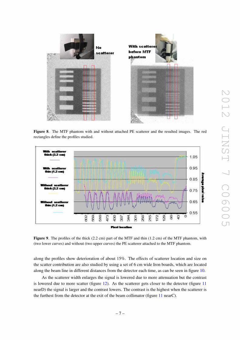
2012 JINST 7 C06005
Figure 8 The MTF phantom with and without attached PE scatterer and the resulted images The redrectangles define the profiles studied
Figure 9 The profiles of the thick (22 cm) part of the MTF and thin (12 cm) of the MTF phantom with(two lower curves) and without (two upper curves) the PE scatterer attached to the MTF phantom
along the profiles show deterioration of about 15 The effects of scatterer location and size onthe scatter contribution are also studied by using a set of 6 cm wide Iron boards which are locatedalong the beam line in different distances from the detector each time as can be seen in figure 10
As the scatterer width enlarges the signal is lowered due to more attenuation but the contrastis lowered due to more scatter (figure 12) As the scatterer gets closer to the detector (figure 11nearD) the signal is larger and the contrast lowers The contrast is the highest when the scatterer isthe furthest from the detector at the exit of the beam collimator (figure 11 nearC)
ndash 7 ndash
2012 JINST 7 C06005
Figure 10 The experimental layout for Iron scatterer location and size influence on the image quality study
Figure 11 The profiles of the MTF Phantom image for different locations (mid-middle of beam line nearCmdash near the beam collimator nearD mdash near the detector) of scatterer in the beam line
The results from the above experiments show we can rely on the measurement of contrast asindicator for scatter contribution in the layout of our setup
32 Lowering the scatter from the surroundings
One of the largest scatter contributions in the experiment comes from the neutrons scattered fromthe surroundings Due to the 4π nature of our neutron source and the fact that the experimenttakes place in a sealed hall we expect background neutrons to arrive at the detector Several at-tempts were made to lower the scatter from which the most fruitful was enlarging the shielding ofthe neutron source which raised the SNR in the air profiles of the fan beam configuration from 41to 751 to 91 in consecutive experiments in which a layer of 78 cm wide borated PE was addedeach time to shield the generator As a consequence a massive generator shield was designed onthe basis of former works [5] and related calculations The generator shield was made of 10 cm
ndash 8 ndash
2012 JINST 7 C06005
Figure 12 The profiles of the MTF Phantom image for different scatterer sizes in the same location (middleof beam line) in the beam line
wide iron serving as the inelastic scatterer around the generator tube surrounded by a 50 cm wideborated polyethylene rich material in H and B with high affinity to capture the already ldquosloweddownrdquo neutrons followed by a 5 cm lead shield in order to ldquocatchrdquo the gammas that emerge fromthe reactions between the boron and hydrogen and the incoming neutrons The contrasts in coneand fan configurationsrsquo images were compared between the setup before and after using the mas-sive shield (figure 13) The Contrast is better using the massive generator shield The Contrast isbetter in fan than in cone configuration (both massive shield setup)
33 Optimization of the moderating material
The beam collimator was optimized in respect to the moderating material within the barrelFor simplicity and ease of use three different materials were used water Borax
(Na2B4O7middot10H2O) ρ=173 grcm3 and Borax and water mixture (Na2B4O7middot14H2O) ρ = 209grcm3 Three consecutive experiments were carried out with the different moderating materials
The beam was monitored using the reference detector (figure 14) and the results were normal-ized accordingly
Figures 15ndash19 show the resulted images and related graphs of the experiments Table 2 sum-marizes the calculated contrasts and SNR values from the resulted images
In figure 17 it can be seen that the signal for the Borax and water mixture derived from thecone air images (figure 16) is the lowest of the three moderating materials indicating less scatteredparticles arriving at the detector and contributing to the signal
In figure 18 it can be seen that the contrast in the cone configuration for the PSF image is bestfor the Borax and water mixture moderating material In figure 19 the SNR is the highest for theBorax and water mixture as a moderating material in the images of the fan beam configuration air
ndash 9 ndash
2012 JINST 7 C06005
Figure 13 PSF profiles with fan (blue) and cone (fuchsia) configuration for the massive shield for cone(yellow) configuration without the massive shield
Figure 14 The beam (signal) as a function of time measured by the beam reference detector
images Both indications show that the scattered contribution that influence both IQ parameters(contrast and SNR) is lower when using a Borax and water mixture as the moderating materialwithin the beam collimator
ndash 10 ndash
2012 JINST 7 C06005
Figure 15 The PSF resulted images and their relative profiles (below each) for cone configuration (left) fanconfiguration (mid) The right image is the fan configuration air image
Figure 16 The cone configuration air image and its resulted profile
Table 2 The contrasts and SNR values for the three different moderating materials for the two beam con-figurations
Moderating materialsFAN Config CONE configSNRminus1(air profiles) Contrast PSF Contrast PSF
BORAX 011plusmn1 097plusmn1 079plusmn1BampW 0017plusmn1 098plusmn1 088plusmn1Water 0088plusmn1 089plusmn1 081plusmn1
In the analysis of the water and Borax moderating materials a slight preference for the Boraxover the water is seen in all IQ aspects as a moderating material
The resulted contrasts and SNR values are summarized in table 2 It is clearly seen that theBorax and water mixture as the moderating material in the beam collimator gives the best IQ resultsThe contrasts values are better for fan configuration than those for cone configuration for all themoderating materials Comparing the results of the Borax and Water moderating materials onecan see that there is a slight advantage to the Borax on water
ndash 11 ndash
2012 JINST 7 C06005
Figure 17 The air image profile for the cone configuration for the three moderating materials The tableshows the averaged differences ratios for the three(B-Borax W-water BampW-Boraxampwater)
Figure 18 The PSF profile for the 3 different moderating materials for cone configuration
ndash 12 ndash
2012 JINST 7 C06005
Figure 19 The profiles of the air images in fan configuration for the different moderating materials
Table 3 Simulation contrast results
Moderating materialsFAN Configuration CONE configurationContrast PSF Contrast PSF
BORAX 083plusmn10 064 plusmn10BampW 091 plusmn10 070plusmn10Water 083 plusmn10 064plusmn10
4 Simulation results
As part of our study the experimental setup was imbedded into GEANT4 and optimized runs werecarried out in different manners A comparison between the three different moderating materialsBorax Borax amp water mixture and water in both fan and cone configurations was made by asimulation of the PSF phantom Figures 20 21 show the profiles of the phantom simulation resultsfor the cone and fan configurations with the three different moderating materials The graphs showthe energy deposited in each fiber in the detector for all the cases
The contrasts were calculated for the simulated PSF phantom within the geometry of the ex-periment as stated above The results are shown in table 3 where it can be seen that the contrastsare always better as expected in the fan configuration The contrasts are best for Borax and watermixture and rather similar for Borax and water for both configurations
In the analysis of the simulationsrsquo results we observed the different components of the energydeposited in the imaging detector The ratios of the direct and scatter radiation contributions andthe total radiation energies for the fan and cone beam configurations were calculated The resultedgraphs and ratios for the direct neutrons component are shown in table 4 and figures 22 23 for thethree different moderating materials It can be observed that the contribution of the direct neutron
ndash 13 ndash
2012 JINST 7 C06005
Figure 20 The phantom profiles for the cone beam configuration for three different moderating materialsBorax Borax amp water mixture and water
Figure 21 The phantom profiles for the fan beam configuration for three different moderating materialsBorax Borax amp water mixture and water
radiation is always larger in the fan configuration in comparison to the cone configuration Forboth configurations the Borax amp water solution gives the highest ratio of direct radiation to totalradiation from the three examined moderating materials
ndash 14 ndash
2012 JINST 7 C06005
Table 4 The average ratios of the direct neutrons radiation energy contribution and the total detected radia-tion energy are shown for the fan and cone configurations for the three different moderating materials
Moderating materialsFAN Configura-tion
CONE configura-tion
DirectRadiation energy contribution []
BORAX 961plusmn17 895plusmn29BampW 970plusmn17 903plusmn27Water 942plusmn20 882plusmn29
Figure 22 The ratios of the direct neutrons radiation contribution and the total radiation detected in eachfiber for the fan configuration and for the three different moderating materials
5 Conclusions
The usage of the Borax and water mixture solution as the moderating material gives the best IQfrom the three different moderating materials which are studied The IQ measures are the SNRand the contrasts in the image The experimental results are consistent with the related simulationThe superiority of the Borax and water solution is for both configurations however comparing theconfigurations for each of the moderating materials we find better IQ for the fan configuration asexpected
ndash 15 ndash
2012 JINST 7 C06005
Figure 23 The ratios of the direct neutrons radiation contribution and the total radiation detected in eachfiber for the cone configuration and for the three different moderating materials
The surroundingsrsquo scatter is reduced meaningfully using a dedicated massive generator shieldwhich was built based on experimental and simulation studies and tested successfully for provenefficiency
As a consequence a dedicated collimator for a D-T generator 142 MeV Fast Neutrons isdeveloped for imaging purposes using the massive generator shield and the Borax and watermixture as the moderating material
References
[1] I Sabo-Napadensky and O Amir Reduction of scattering artifact in multislice CT MJ Flynn edProc SPIE 5745 (2005) 983
[2] J Star-Lack et al Efficient scatter correction using asymmetric kernels Proc SPIE 7258 (2009)72581Z
[3] BR Grogan The development of a parameterized scatter removal algorithm for nuclear materialsidentification system imaging PhD dissertation University of Tennessee Knoxville USA (2010)
[4] I Mor et al High spatial resolution fast-neutron imaging detectors for pulsed fast-neutrontransmission spectroscopy 2009 JINST 4 P05016
[5] American National Standards Institute Neutron radiation protection shielding mdash design principles andconsiderations for the choice of appropriate materials ISO 141522001 ANSI USA (2007)
ndash 16 ndash
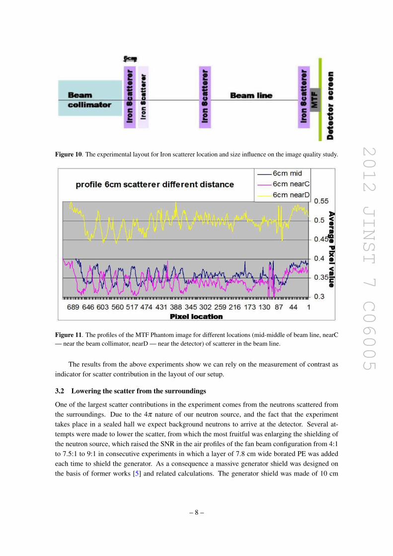
2012 JINST 7 C06005
Figure 10 The experimental layout for Iron scatterer location and size influence on the image quality study
Figure 11 The profiles of the MTF Phantom image for different locations (mid-middle of beam line nearCmdash near the beam collimator nearD mdash near the detector) of scatterer in the beam line
The results from the above experiments show we can rely on the measurement of contrast asindicator for scatter contribution in the layout of our setup
32 Lowering the scatter from the surroundings
One of the largest scatter contributions in the experiment comes from the neutrons scattered fromthe surroundings Due to the 4π nature of our neutron source and the fact that the experimenttakes place in a sealed hall we expect background neutrons to arrive at the detector Several at-tempts were made to lower the scatter from which the most fruitful was enlarging the shielding ofthe neutron source which raised the SNR in the air profiles of the fan beam configuration from 41to 751 to 91 in consecutive experiments in which a layer of 78 cm wide borated PE was addedeach time to shield the generator As a consequence a massive generator shield was designed onthe basis of former works [5] and related calculations The generator shield was made of 10 cm
ndash 8 ndash
2012 JINST 7 C06005
Figure 12 The profiles of the MTF Phantom image for different scatterer sizes in the same location (middleof beam line) in the beam line
wide iron serving as the inelastic scatterer around the generator tube surrounded by a 50 cm wideborated polyethylene rich material in H and B with high affinity to capture the already ldquosloweddownrdquo neutrons followed by a 5 cm lead shield in order to ldquocatchrdquo the gammas that emerge fromthe reactions between the boron and hydrogen and the incoming neutrons The contrasts in coneand fan configurationsrsquo images were compared between the setup before and after using the mas-sive shield (figure 13) The Contrast is better using the massive generator shield The Contrast isbetter in fan than in cone configuration (both massive shield setup)
33 Optimization of the moderating material
The beam collimator was optimized in respect to the moderating material within the barrelFor simplicity and ease of use three different materials were used water Borax
(Na2B4O7middot10H2O) ρ=173 grcm3 and Borax and water mixture (Na2B4O7middot14H2O) ρ = 209grcm3 Three consecutive experiments were carried out with the different moderating materials
The beam was monitored using the reference detector (figure 14) and the results were normal-ized accordingly
Figures 15ndash19 show the resulted images and related graphs of the experiments Table 2 sum-marizes the calculated contrasts and SNR values from the resulted images
In figure 17 it can be seen that the signal for the Borax and water mixture derived from thecone air images (figure 16) is the lowest of the three moderating materials indicating less scatteredparticles arriving at the detector and contributing to the signal
In figure 18 it can be seen that the contrast in the cone configuration for the PSF image is bestfor the Borax and water mixture moderating material In figure 19 the SNR is the highest for theBorax and water mixture as a moderating material in the images of the fan beam configuration air
ndash 9 ndash
2012 JINST 7 C06005
Figure 13 PSF profiles with fan (blue) and cone (fuchsia) configuration for the massive shield for cone(yellow) configuration without the massive shield
Figure 14 The beam (signal) as a function of time measured by the beam reference detector
images Both indications show that the scattered contribution that influence both IQ parameters(contrast and SNR) is lower when using a Borax and water mixture as the moderating materialwithin the beam collimator
ndash 10 ndash
2012 JINST 7 C06005
Figure 15 The PSF resulted images and their relative profiles (below each) for cone configuration (left) fanconfiguration (mid) The right image is the fan configuration air image
Figure 16 The cone configuration air image and its resulted profile
Table 2 The contrasts and SNR values for the three different moderating materials for the two beam con-figurations
Moderating materialsFAN Config CONE configSNRminus1(air profiles) Contrast PSF Contrast PSF
BORAX 011plusmn1 097plusmn1 079plusmn1BampW 0017plusmn1 098plusmn1 088plusmn1Water 0088plusmn1 089plusmn1 081plusmn1
In the analysis of the water and Borax moderating materials a slight preference for the Boraxover the water is seen in all IQ aspects as a moderating material
The resulted contrasts and SNR values are summarized in table 2 It is clearly seen that theBorax and water mixture as the moderating material in the beam collimator gives the best IQ resultsThe contrasts values are better for fan configuration than those for cone configuration for all themoderating materials Comparing the results of the Borax and Water moderating materials onecan see that there is a slight advantage to the Borax on water
ndash 11 ndash
2012 JINST 7 C06005
Figure 17 The air image profile for the cone configuration for the three moderating materials The tableshows the averaged differences ratios for the three(B-Borax W-water BampW-Boraxampwater)
Figure 18 The PSF profile for the 3 different moderating materials for cone configuration
ndash 12 ndash
2012 JINST 7 C06005
Figure 19 The profiles of the air images in fan configuration for the different moderating materials
Table 3 Simulation contrast results
Moderating materialsFAN Configuration CONE configurationContrast PSF Contrast PSF
BORAX 083plusmn10 064 plusmn10BampW 091 plusmn10 070plusmn10Water 083 plusmn10 064plusmn10
4 Simulation results
As part of our study the experimental setup was imbedded into GEANT4 and optimized runs werecarried out in different manners A comparison between the three different moderating materialsBorax Borax amp water mixture and water in both fan and cone configurations was made by asimulation of the PSF phantom Figures 20 21 show the profiles of the phantom simulation resultsfor the cone and fan configurations with the three different moderating materials The graphs showthe energy deposited in each fiber in the detector for all the cases
The contrasts were calculated for the simulated PSF phantom within the geometry of the ex-periment as stated above The results are shown in table 3 where it can be seen that the contrastsare always better as expected in the fan configuration The contrasts are best for Borax and watermixture and rather similar for Borax and water for both configurations
In the analysis of the simulationsrsquo results we observed the different components of the energydeposited in the imaging detector The ratios of the direct and scatter radiation contributions andthe total radiation energies for the fan and cone beam configurations were calculated The resultedgraphs and ratios for the direct neutrons component are shown in table 4 and figures 22 23 for thethree different moderating materials It can be observed that the contribution of the direct neutron
ndash 13 ndash
2012 JINST 7 C06005
Figure 20 The phantom profiles for the cone beam configuration for three different moderating materialsBorax Borax amp water mixture and water
Figure 21 The phantom profiles for the fan beam configuration for three different moderating materialsBorax Borax amp water mixture and water
radiation is always larger in the fan configuration in comparison to the cone configuration Forboth configurations the Borax amp water solution gives the highest ratio of direct radiation to totalradiation from the three examined moderating materials
ndash 14 ndash
2012 JINST 7 C06005
Table 4 The average ratios of the direct neutrons radiation energy contribution and the total detected radia-tion energy are shown for the fan and cone configurations for the three different moderating materials
Moderating materialsFAN Configura-tion
CONE configura-tion
DirectRadiation energy contribution []
BORAX 961plusmn17 895plusmn29BampW 970plusmn17 903plusmn27Water 942plusmn20 882plusmn29
Figure 22 The ratios of the direct neutrons radiation contribution and the total radiation detected in eachfiber for the fan configuration and for the three different moderating materials
5 Conclusions
The usage of the Borax and water mixture solution as the moderating material gives the best IQfrom the three different moderating materials which are studied The IQ measures are the SNRand the contrasts in the image The experimental results are consistent with the related simulationThe superiority of the Borax and water solution is for both configurations however comparing theconfigurations for each of the moderating materials we find better IQ for the fan configuration asexpected
ndash 15 ndash
2012 JINST 7 C06005
Figure 23 The ratios of the direct neutrons radiation contribution and the total radiation detected in eachfiber for the cone configuration and for the three different moderating materials
The surroundingsrsquo scatter is reduced meaningfully using a dedicated massive generator shieldwhich was built based on experimental and simulation studies and tested successfully for provenefficiency
As a consequence a dedicated collimator for a D-T generator 142 MeV Fast Neutrons isdeveloped for imaging purposes using the massive generator shield and the Borax and watermixture as the moderating material
References
[1] I Sabo-Napadensky and O Amir Reduction of scattering artifact in multislice CT MJ Flynn edProc SPIE 5745 (2005) 983
[2] J Star-Lack et al Efficient scatter correction using asymmetric kernels Proc SPIE 7258 (2009)72581Z
[3] BR Grogan The development of a parameterized scatter removal algorithm for nuclear materialsidentification system imaging PhD dissertation University of Tennessee Knoxville USA (2010)
[4] I Mor et al High spatial resolution fast-neutron imaging detectors for pulsed fast-neutrontransmission spectroscopy 2009 JINST 4 P05016
[5] American National Standards Institute Neutron radiation protection shielding mdash design principles andconsiderations for the choice of appropriate materials ISO 141522001 ANSI USA (2007)
ndash 16 ndash
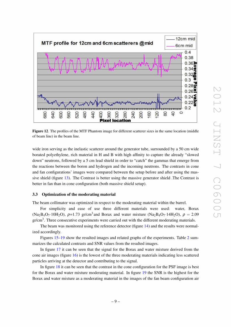
2012 JINST 7 C06005
Figure 12 The profiles of the MTF Phantom image for different scatterer sizes in the same location (middleof beam line) in the beam line
wide iron serving as the inelastic scatterer around the generator tube surrounded by a 50 cm wideborated polyethylene rich material in H and B with high affinity to capture the already ldquosloweddownrdquo neutrons followed by a 5 cm lead shield in order to ldquocatchrdquo the gammas that emerge fromthe reactions between the boron and hydrogen and the incoming neutrons The contrasts in coneand fan configurationsrsquo images were compared between the setup before and after using the mas-sive shield (figure 13) The Contrast is better using the massive generator shield The Contrast isbetter in fan than in cone configuration (both massive shield setup)
33 Optimization of the moderating material
The beam collimator was optimized in respect to the moderating material within the barrelFor simplicity and ease of use three different materials were used water Borax
(Na2B4O7middot10H2O) ρ=173 grcm3 and Borax and water mixture (Na2B4O7middot14H2O) ρ = 209grcm3 Three consecutive experiments were carried out with the different moderating materials
The beam was monitored using the reference detector (figure 14) and the results were normal-ized accordingly
Figures 15ndash19 show the resulted images and related graphs of the experiments Table 2 sum-marizes the calculated contrasts and SNR values from the resulted images
In figure 17 it can be seen that the signal for the Borax and water mixture derived from thecone air images (figure 16) is the lowest of the three moderating materials indicating less scatteredparticles arriving at the detector and contributing to the signal
In figure 18 it can be seen that the contrast in the cone configuration for the PSF image is bestfor the Borax and water mixture moderating material In figure 19 the SNR is the highest for theBorax and water mixture as a moderating material in the images of the fan beam configuration air
ndash 9 ndash
2012 JINST 7 C06005
Figure 13 PSF profiles with fan (blue) and cone (fuchsia) configuration for the massive shield for cone(yellow) configuration without the massive shield
Figure 14 The beam (signal) as a function of time measured by the beam reference detector
images Both indications show that the scattered contribution that influence both IQ parameters(contrast and SNR) is lower when using a Borax and water mixture as the moderating materialwithin the beam collimator
ndash 10 ndash
2012 JINST 7 C06005
Figure 15 The PSF resulted images and their relative profiles (below each) for cone configuration (left) fanconfiguration (mid) The right image is the fan configuration air image
Figure 16 The cone configuration air image and its resulted profile
Table 2 The contrasts and SNR values for the three different moderating materials for the two beam con-figurations
Moderating materialsFAN Config CONE configSNRminus1(air profiles) Contrast PSF Contrast PSF
BORAX 011plusmn1 097plusmn1 079plusmn1BampW 0017plusmn1 098plusmn1 088plusmn1Water 0088plusmn1 089plusmn1 081plusmn1
In the analysis of the water and Borax moderating materials a slight preference for the Boraxover the water is seen in all IQ aspects as a moderating material
The resulted contrasts and SNR values are summarized in table 2 It is clearly seen that theBorax and water mixture as the moderating material in the beam collimator gives the best IQ resultsThe contrasts values are better for fan configuration than those for cone configuration for all themoderating materials Comparing the results of the Borax and Water moderating materials onecan see that there is a slight advantage to the Borax on water
ndash 11 ndash
2012 JINST 7 C06005
Figure 17 The air image profile for the cone configuration for the three moderating materials The tableshows the averaged differences ratios for the three(B-Borax W-water BampW-Boraxampwater)
Figure 18 The PSF profile for the 3 different moderating materials for cone configuration
ndash 12 ndash
2012 JINST 7 C06005
Figure 19 The profiles of the air images in fan configuration for the different moderating materials
Table 3 Simulation contrast results
Moderating materialsFAN Configuration CONE configurationContrast PSF Contrast PSF
BORAX 083plusmn10 064 plusmn10BampW 091 plusmn10 070plusmn10Water 083 plusmn10 064plusmn10
4 Simulation results
As part of our study the experimental setup was imbedded into GEANT4 and optimized runs werecarried out in different manners A comparison between the three different moderating materialsBorax Borax amp water mixture and water in both fan and cone configurations was made by asimulation of the PSF phantom Figures 20 21 show the profiles of the phantom simulation resultsfor the cone and fan configurations with the three different moderating materials The graphs showthe energy deposited in each fiber in the detector for all the cases
The contrasts were calculated for the simulated PSF phantom within the geometry of the ex-periment as stated above The results are shown in table 3 where it can be seen that the contrastsare always better as expected in the fan configuration The contrasts are best for Borax and watermixture and rather similar for Borax and water for both configurations
In the analysis of the simulationsrsquo results we observed the different components of the energydeposited in the imaging detector The ratios of the direct and scatter radiation contributions andthe total radiation energies for the fan and cone beam configurations were calculated The resultedgraphs and ratios for the direct neutrons component are shown in table 4 and figures 22 23 for thethree different moderating materials It can be observed that the contribution of the direct neutron
ndash 13 ndash
2012 JINST 7 C06005
Figure 20 The phantom profiles for the cone beam configuration for three different moderating materialsBorax Borax amp water mixture and water
Figure 21 The phantom profiles for the fan beam configuration for three different moderating materialsBorax Borax amp water mixture and water
radiation is always larger in the fan configuration in comparison to the cone configuration Forboth configurations the Borax amp water solution gives the highest ratio of direct radiation to totalradiation from the three examined moderating materials
ndash 14 ndash
2012 JINST 7 C06005
Table 4 The average ratios of the direct neutrons radiation energy contribution and the total detected radia-tion energy are shown for the fan and cone configurations for the three different moderating materials
Moderating materialsFAN Configura-tion
CONE configura-tion
DirectRadiation energy contribution []
BORAX 961plusmn17 895plusmn29BampW 970plusmn17 903plusmn27Water 942plusmn20 882plusmn29
Figure 22 The ratios of the direct neutrons radiation contribution and the total radiation detected in eachfiber for the fan configuration and for the three different moderating materials
5 Conclusions
The usage of the Borax and water mixture solution as the moderating material gives the best IQfrom the three different moderating materials which are studied The IQ measures are the SNRand the contrasts in the image The experimental results are consistent with the related simulationThe superiority of the Borax and water solution is for both configurations however comparing theconfigurations for each of the moderating materials we find better IQ for the fan configuration asexpected
ndash 15 ndash
2012 JINST 7 C06005
Figure 23 The ratios of the direct neutrons radiation contribution and the total radiation detected in eachfiber for the cone configuration and for the three different moderating materials
The surroundingsrsquo scatter is reduced meaningfully using a dedicated massive generator shieldwhich was built based on experimental and simulation studies and tested successfully for provenefficiency
As a consequence a dedicated collimator for a D-T generator 142 MeV Fast Neutrons isdeveloped for imaging purposes using the massive generator shield and the Borax and watermixture as the moderating material
References
[1] I Sabo-Napadensky and O Amir Reduction of scattering artifact in multislice CT MJ Flynn edProc SPIE 5745 (2005) 983
[2] J Star-Lack et al Efficient scatter correction using asymmetric kernels Proc SPIE 7258 (2009)72581Z
[3] BR Grogan The development of a parameterized scatter removal algorithm for nuclear materialsidentification system imaging PhD dissertation University of Tennessee Knoxville USA (2010)
[4] I Mor et al High spatial resolution fast-neutron imaging detectors for pulsed fast-neutrontransmission spectroscopy 2009 JINST 4 P05016
[5] American National Standards Institute Neutron radiation protection shielding mdash design principles andconsiderations for the choice of appropriate materials ISO 141522001 ANSI USA (2007)
ndash 16 ndash
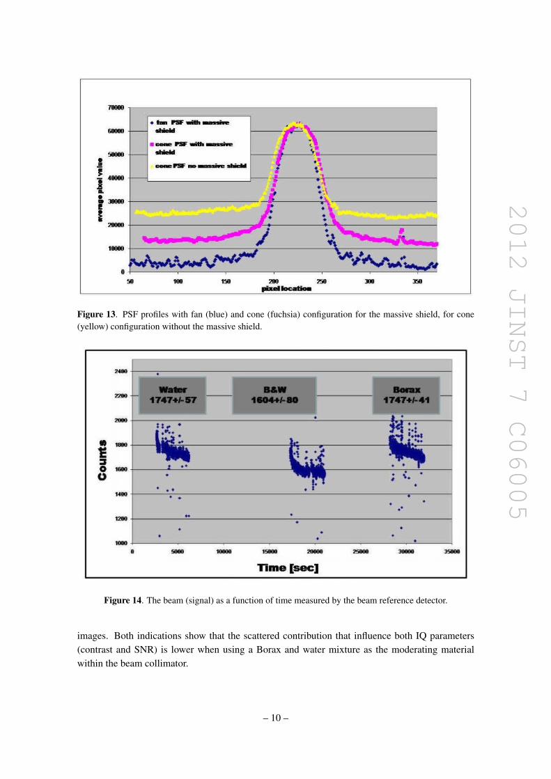
2012 JINST 7 C06005
Figure 13 PSF profiles with fan (blue) and cone (fuchsia) configuration for the massive shield for cone(yellow) configuration without the massive shield
Figure 14 The beam (signal) as a function of time measured by the beam reference detector
images Both indications show that the scattered contribution that influence both IQ parameters(contrast and SNR) is lower when using a Borax and water mixture as the moderating materialwithin the beam collimator
ndash 10 ndash
2012 JINST 7 C06005
Figure 15 The PSF resulted images and their relative profiles (below each) for cone configuration (left) fanconfiguration (mid) The right image is the fan configuration air image
Figure 16 The cone configuration air image and its resulted profile
Table 2 The contrasts and SNR values for the three different moderating materials for the two beam con-figurations
Moderating materialsFAN Config CONE configSNRminus1(air profiles) Contrast PSF Contrast PSF
BORAX 011plusmn1 097plusmn1 079plusmn1BampW 0017plusmn1 098plusmn1 088plusmn1Water 0088plusmn1 089plusmn1 081plusmn1
In the analysis of the water and Borax moderating materials a slight preference for the Boraxover the water is seen in all IQ aspects as a moderating material
The resulted contrasts and SNR values are summarized in table 2 It is clearly seen that theBorax and water mixture as the moderating material in the beam collimator gives the best IQ resultsThe contrasts values are better for fan configuration than those for cone configuration for all themoderating materials Comparing the results of the Borax and Water moderating materials onecan see that there is a slight advantage to the Borax on water
ndash 11 ndash
2012 JINST 7 C06005
Figure 17 The air image profile for the cone configuration for the three moderating materials The tableshows the averaged differences ratios for the three(B-Borax W-water BampW-Boraxampwater)
Figure 18 The PSF profile for the 3 different moderating materials for cone configuration
ndash 12 ndash
2012 JINST 7 C06005
Figure 19 The profiles of the air images in fan configuration for the different moderating materials
Table 3 Simulation contrast results
Moderating materialsFAN Configuration CONE configurationContrast PSF Contrast PSF
BORAX 083plusmn10 064 plusmn10BampW 091 plusmn10 070plusmn10Water 083 plusmn10 064plusmn10
4 Simulation results
As part of our study the experimental setup was imbedded into GEANT4 and optimized runs werecarried out in different manners A comparison between the three different moderating materialsBorax Borax amp water mixture and water in both fan and cone configurations was made by asimulation of the PSF phantom Figures 20 21 show the profiles of the phantom simulation resultsfor the cone and fan configurations with the three different moderating materials The graphs showthe energy deposited in each fiber in the detector for all the cases
The contrasts were calculated for the simulated PSF phantom within the geometry of the ex-periment as stated above The results are shown in table 3 where it can be seen that the contrastsare always better as expected in the fan configuration The contrasts are best for Borax and watermixture and rather similar for Borax and water for both configurations
In the analysis of the simulationsrsquo results we observed the different components of the energydeposited in the imaging detector The ratios of the direct and scatter radiation contributions andthe total radiation energies for the fan and cone beam configurations were calculated The resultedgraphs and ratios for the direct neutrons component are shown in table 4 and figures 22 23 for thethree different moderating materials It can be observed that the contribution of the direct neutron
ndash 13 ndash
2012 JINST 7 C06005
Figure 20 The phantom profiles for the cone beam configuration for three different moderating materialsBorax Borax amp water mixture and water
Figure 21 The phantom profiles for the fan beam configuration for three different moderating materialsBorax Borax amp water mixture and water
radiation is always larger in the fan configuration in comparison to the cone configuration Forboth configurations the Borax amp water solution gives the highest ratio of direct radiation to totalradiation from the three examined moderating materials
ndash 14 ndash
2012 JINST 7 C06005
Table 4 The average ratios of the direct neutrons radiation energy contribution and the total detected radia-tion energy are shown for the fan and cone configurations for the three different moderating materials
Moderating materialsFAN Configura-tion
CONE configura-tion
DirectRadiation energy contribution []
BORAX 961plusmn17 895plusmn29BampW 970plusmn17 903plusmn27Water 942plusmn20 882plusmn29
Figure 22 The ratios of the direct neutrons radiation contribution and the total radiation detected in eachfiber for the fan configuration and for the three different moderating materials
5 Conclusions
The usage of the Borax and water mixture solution as the moderating material gives the best IQfrom the three different moderating materials which are studied The IQ measures are the SNRand the contrasts in the image The experimental results are consistent with the related simulationThe superiority of the Borax and water solution is for both configurations however comparing theconfigurations for each of the moderating materials we find better IQ for the fan configuration asexpected
ndash 15 ndash
2012 JINST 7 C06005
Figure 23 The ratios of the direct neutrons radiation contribution and the total radiation detected in eachfiber for the cone configuration and for the three different moderating materials
The surroundingsrsquo scatter is reduced meaningfully using a dedicated massive generator shieldwhich was built based on experimental and simulation studies and tested successfully for provenefficiency
As a consequence a dedicated collimator for a D-T generator 142 MeV Fast Neutrons isdeveloped for imaging purposes using the massive generator shield and the Borax and watermixture as the moderating material
References
[1] I Sabo-Napadensky and O Amir Reduction of scattering artifact in multislice CT MJ Flynn edProc SPIE 5745 (2005) 983
[2] J Star-Lack et al Efficient scatter correction using asymmetric kernels Proc SPIE 7258 (2009)72581Z
[3] BR Grogan The development of a parameterized scatter removal algorithm for nuclear materialsidentification system imaging PhD dissertation University of Tennessee Knoxville USA (2010)
[4] I Mor et al High spatial resolution fast-neutron imaging detectors for pulsed fast-neutrontransmission spectroscopy 2009 JINST 4 P05016
[5] American National Standards Institute Neutron radiation protection shielding mdash design principles andconsiderations for the choice of appropriate materials ISO 141522001 ANSI USA (2007)
ndash 16 ndash
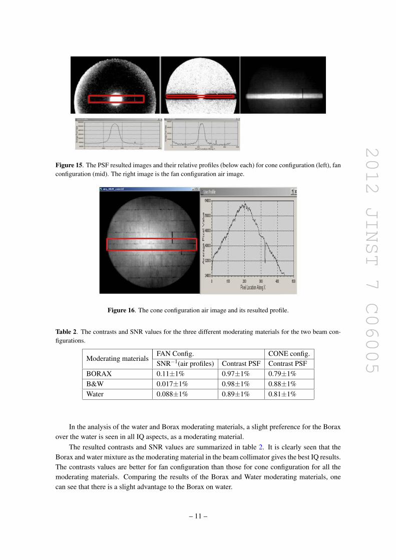
2012 JINST 7 C06005
Figure 15 The PSF resulted images and their relative profiles (below each) for cone configuration (left) fanconfiguration (mid) The right image is the fan configuration air image
Figure 16 The cone configuration air image and its resulted profile
Table 2 The contrasts and SNR values for the three different moderating materials for the two beam con-figurations
Moderating materialsFAN Config CONE configSNRminus1(air profiles) Contrast PSF Contrast PSF
BORAX 011plusmn1 097plusmn1 079plusmn1BampW 0017plusmn1 098plusmn1 088plusmn1Water 0088plusmn1 089plusmn1 081plusmn1
In the analysis of the water and Borax moderating materials a slight preference for the Boraxover the water is seen in all IQ aspects as a moderating material
The resulted contrasts and SNR values are summarized in table 2 It is clearly seen that theBorax and water mixture as the moderating material in the beam collimator gives the best IQ resultsThe contrasts values are better for fan configuration than those for cone configuration for all themoderating materials Comparing the results of the Borax and Water moderating materials onecan see that there is a slight advantage to the Borax on water
ndash 11 ndash
2012 JINST 7 C06005
Figure 17 The air image profile for the cone configuration for the three moderating materials The tableshows the averaged differences ratios for the three(B-Borax W-water BampW-Boraxampwater)
Figure 18 The PSF profile for the 3 different moderating materials for cone configuration
ndash 12 ndash
2012 JINST 7 C06005
Figure 19 The profiles of the air images in fan configuration for the different moderating materials
Table 3 Simulation contrast results
Moderating materialsFAN Configuration CONE configurationContrast PSF Contrast PSF
BORAX 083plusmn10 064 plusmn10BampW 091 plusmn10 070plusmn10Water 083 plusmn10 064plusmn10
4 Simulation results
As part of our study the experimental setup was imbedded into GEANT4 and optimized runs werecarried out in different manners A comparison between the three different moderating materialsBorax Borax amp water mixture and water in both fan and cone configurations was made by asimulation of the PSF phantom Figures 20 21 show the profiles of the phantom simulation resultsfor the cone and fan configurations with the three different moderating materials The graphs showthe energy deposited in each fiber in the detector for all the cases
The contrasts were calculated for the simulated PSF phantom within the geometry of the ex-periment as stated above The results are shown in table 3 where it can be seen that the contrastsare always better as expected in the fan configuration The contrasts are best for Borax and watermixture and rather similar for Borax and water for both configurations
In the analysis of the simulationsrsquo results we observed the different components of the energydeposited in the imaging detector The ratios of the direct and scatter radiation contributions andthe total radiation energies for the fan and cone beam configurations were calculated The resultedgraphs and ratios for the direct neutrons component are shown in table 4 and figures 22 23 for thethree different moderating materials It can be observed that the contribution of the direct neutron
ndash 13 ndash
2012 JINST 7 C06005
Figure 20 The phantom profiles for the cone beam configuration for three different moderating materialsBorax Borax amp water mixture and water
Figure 21 The phantom profiles for the fan beam configuration for three different moderating materialsBorax Borax amp water mixture and water
radiation is always larger in the fan configuration in comparison to the cone configuration Forboth configurations the Borax amp water solution gives the highest ratio of direct radiation to totalradiation from the three examined moderating materials
ndash 14 ndash
2012 JINST 7 C06005
Table 4 The average ratios of the direct neutrons radiation energy contribution and the total detected radia-tion energy are shown for the fan and cone configurations for the three different moderating materials
Moderating materialsFAN Configura-tion
CONE configura-tion
DirectRadiation energy contribution []
BORAX 961plusmn17 895plusmn29BampW 970plusmn17 903plusmn27Water 942plusmn20 882plusmn29
Figure 22 The ratios of the direct neutrons radiation contribution and the total radiation detected in eachfiber for the fan configuration and for the three different moderating materials
5 Conclusions
The usage of the Borax and water mixture solution as the moderating material gives the best IQfrom the three different moderating materials which are studied The IQ measures are the SNRand the contrasts in the image The experimental results are consistent with the related simulationThe superiority of the Borax and water solution is for both configurations however comparing theconfigurations for each of the moderating materials we find better IQ for the fan configuration asexpected
ndash 15 ndash
2012 JINST 7 C06005
Figure 23 The ratios of the direct neutrons radiation contribution and the total radiation detected in eachfiber for the cone configuration and for the three different moderating materials
The surroundingsrsquo scatter is reduced meaningfully using a dedicated massive generator shieldwhich was built based on experimental and simulation studies and tested successfully for provenefficiency
As a consequence a dedicated collimator for a D-T generator 142 MeV Fast Neutrons isdeveloped for imaging purposes using the massive generator shield and the Borax and watermixture as the moderating material
References
[1] I Sabo-Napadensky and O Amir Reduction of scattering artifact in multislice CT MJ Flynn edProc SPIE 5745 (2005) 983
[2] J Star-Lack et al Efficient scatter correction using asymmetric kernels Proc SPIE 7258 (2009)72581Z
[3] BR Grogan The development of a parameterized scatter removal algorithm for nuclear materialsidentification system imaging PhD dissertation University of Tennessee Knoxville USA (2010)
[4] I Mor et al High spatial resolution fast-neutron imaging detectors for pulsed fast-neutrontransmission spectroscopy 2009 JINST 4 P05016
[5] American National Standards Institute Neutron radiation protection shielding mdash design principles andconsiderations for the choice of appropriate materials ISO 141522001 ANSI USA (2007)
ndash 16 ndash
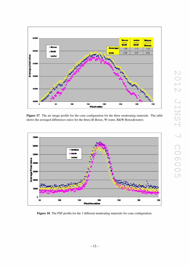
2012 JINST 7 C06005
Figure 17 The air image profile for the cone configuration for the three moderating materials The tableshows the averaged differences ratios for the three(B-Borax W-water BampW-Boraxampwater)
Figure 18 The PSF profile for the 3 different moderating materials for cone configuration
ndash 12 ndash
2012 JINST 7 C06005
Figure 19 The profiles of the air images in fan configuration for the different moderating materials
Table 3 Simulation contrast results
Moderating materialsFAN Configuration CONE configurationContrast PSF Contrast PSF
BORAX 083plusmn10 064 plusmn10BampW 091 plusmn10 070plusmn10Water 083 plusmn10 064plusmn10
4 Simulation results
As part of our study the experimental setup was imbedded into GEANT4 and optimized runs werecarried out in different manners A comparison between the three different moderating materialsBorax Borax amp water mixture and water in both fan and cone configurations was made by asimulation of the PSF phantom Figures 20 21 show the profiles of the phantom simulation resultsfor the cone and fan configurations with the three different moderating materials The graphs showthe energy deposited in each fiber in the detector for all the cases
The contrasts were calculated for the simulated PSF phantom within the geometry of the ex-periment as stated above The results are shown in table 3 where it can be seen that the contrastsare always better as expected in the fan configuration The contrasts are best for Borax and watermixture and rather similar for Borax and water for both configurations
In the analysis of the simulationsrsquo results we observed the different components of the energydeposited in the imaging detector The ratios of the direct and scatter radiation contributions andthe total radiation energies for the fan and cone beam configurations were calculated The resultedgraphs and ratios for the direct neutrons component are shown in table 4 and figures 22 23 for thethree different moderating materials It can be observed that the contribution of the direct neutron
ndash 13 ndash
2012 JINST 7 C06005
Figure 20 The phantom profiles for the cone beam configuration for three different moderating materialsBorax Borax amp water mixture and water
Figure 21 The phantom profiles for the fan beam configuration for three different moderating materialsBorax Borax amp water mixture and water
radiation is always larger in the fan configuration in comparison to the cone configuration Forboth configurations the Borax amp water solution gives the highest ratio of direct radiation to totalradiation from the three examined moderating materials
ndash 14 ndash
2012 JINST 7 C06005
Table 4 The average ratios of the direct neutrons radiation energy contribution and the total detected radia-tion energy are shown for the fan and cone configurations for the three different moderating materials
Moderating materialsFAN Configura-tion
CONE configura-tion
DirectRadiation energy contribution []
BORAX 961plusmn17 895plusmn29BampW 970plusmn17 903plusmn27Water 942plusmn20 882plusmn29
Figure 22 The ratios of the direct neutrons radiation contribution and the total radiation detected in eachfiber for the fan configuration and for the three different moderating materials
5 Conclusions
The usage of the Borax and water mixture solution as the moderating material gives the best IQfrom the three different moderating materials which are studied The IQ measures are the SNRand the contrasts in the image The experimental results are consistent with the related simulationThe superiority of the Borax and water solution is for both configurations however comparing theconfigurations for each of the moderating materials we find better IQ for the fan configuration asexpected
ndash 15 ndash
2012 JINST 7 C06005
Figure 23 The ratios of the direct neutrons radiation contribution and the total radiation detected in eachfiber for the cone configuration and for the three different moderating materials
The surroundingsrsquo scatter is reduced meaningfully using a dedicated massive generator shieldwhich was built based on experimental and simulation studies and tested successfully for provenefficiency
As a consequence a dedicated collimator for a D-T generator 142 MeV Fast Neutrons isdeveloped for imaging purposes using the massive generator shield and the Borax and watermixture as the moderating material
References
[1] I Sabo-Napadensky and O Amir Reduction of scattering artifact in multislice CT MJ Flynn edProc SPIE 5745 (2005) 983
[2] J Star-Lack et al Efficient scatter correction using asymmetric kernels Proc SPIE 7258 (2009)72581Z
[3] BR Grogan The development of a parameterized scatter removal algorithm for nuclear materialsidentification system imaging PhD dissertation University of Tennessee Knoxville USA (2010)
[4] I Mor et al High spatial resolution fast-neutron imaging detectors for pulsed fast-neutrontransmission spectroscopy 2009 JINST 4 P05016
[5] American National Standards Institute Neutron radiation protection shielding mdash design principles andconsiderations for the choice of appropriate materials ISO 141522001 ANSI USA (2007)
ndash 16 ndash
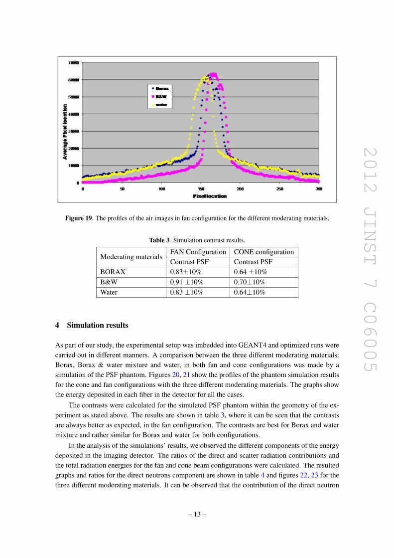
2012 JINST 7 C06005
Figure 19 The profiles of the air images in fan configuration for the different moderating materials
Table 3 Simulation contrast results
Moderating materialsFAN Configuration CONE configurationContrast PSF Contrast PSF
BORAX 083plusmn10 064 plusmn10BampW 091 plusmn10 070plusmn10Water 083 plusmn10 064plusmn10
4 Simulation results
As part of our study the experimental setup was imbedded into GEANT4 and optimized runs werecarried out in different manners A comparison between the three different moderating materialsBorax Borax amp water mixture and water in both fan and cone configurations was made by asimulation of the PSF phantom Figures 20 21 show the profiles of the phantom simulation resultsfor the cone and fan configurations with the three different moderating materials The graphs showthe energy deposited in each fiber in the detector for all the cases
The contrasts were calculated for the simulated PSF phantom within the geometry of the ex-periment as stated above The results are shown in table 3 where it can be seen that the contrastsare always better as expected in the fan configuration The contrasts are best for Borax and watermixture and rather similar for Borax and water for both configurations
In the analysis of the simulationsrsquo results we observed the different components of the energydeposited in the imaging detector The ratios of the direct and scatter radiation contributions andthe total radiation energies for the fan and cone beam configurations were calculated The resultedgraphs and ratios for the direct neutrons component are shown in table 4 and figures 22 23 for thethree different moderating materials It can be observed that the contribution of the direct neutron
ndash 13 ndash
2012 JINST 7 C06005
Figure 20 The phantom profiles for the cone beam configuration for three different moderating materialsBorax Borax amp water mixture and water
Figure 21 The phantom profiles for the fan beam configuration for three different moderating materialsBorax Borax amp water mixture and water
radiation is always larger in the fan configuration in comparison to the cone configuration Forboth configurations the Borax amp water solution gives the highest ratio of direct radiation to totalradiation from the three examined moderating materials
ndash 14 ndash
2012 JINST 7 C06005
Table 4 The average ratios of the direct neutrons radiation energy contribution and the total detected radia-tion energy are shown for the fan and cone configurations for the three different moderating materials
Moderating materialsFAN Configura-tion
CONE configura-tion
DirectRadiation energy contribution []
BORAX 961plusmn17 895plusmn29BampW 970plusmn17 903plusmn27Water 942plusmn20 882plusmn29
Figure 22 The ratios of the direct neutrons radiation contribution and the total radiation detected in eachfiber for the fan configuration and for the three different moderating materials
5 Conclusions
The usage of the Borax and water mixture solution as the moderating material gives the best IQfrom the three different moderating materials which are studied The IQ measures are the SNRand the contrasts in the image The experimental results are consistent with the related simulationThe superiority of the Borax and water solution is for both configurations however comparing theconfigurations for each of the moderating materials we find better IQ for the fan configuration asexpected
ndash 15 ndash
2012 JINST 7 C06005
Figure 23 The ratios of the direct neutrons radiation contribution and the total radiation detected in eachfiber for the cone configuration and for the three different moderating materials
The surroundingsrsquo scatter is reduced meaningfully using a dedicated massive generator shieldwhich was built based on experimental and simulation studies and tested successfully for provenefficiency
As a consequence a dedicated collimator for a D-T generator 142 MeV Fast Neutrons isdeveloped for imaging purposes using the massive generator shield and the Borax and watermixture as the moderating material
References
[1] I Sabo-Napadensky and O Amir Reduction of scattering artifact in multislice CT MJ Flynn edProc SPIE 5745 (2005) 983
[2] J Star-Lack et al Efficient scatter correction using asymmetric kernels Proc SPIE 7258 (2009)72581Z
[3] BR Grogan The development of a parameterized scatter removal algorithm for nuclear materialsidentification system imaging PhD dissertation University of Tennessee Knoxville USA (2010)
[4] I Mor et al High spatial resolution fast-neutron imaging detectors for pulsed fast-neutrontransmission spectroscopy 2009 JINST 4 P05016
[5] American National Standards Institute Neutron radiation protection shielding mdash design principles andconsiderations for the choice of appropriate materials ISO 141522001 ANSI USA (2007)
ndash 16 ndash
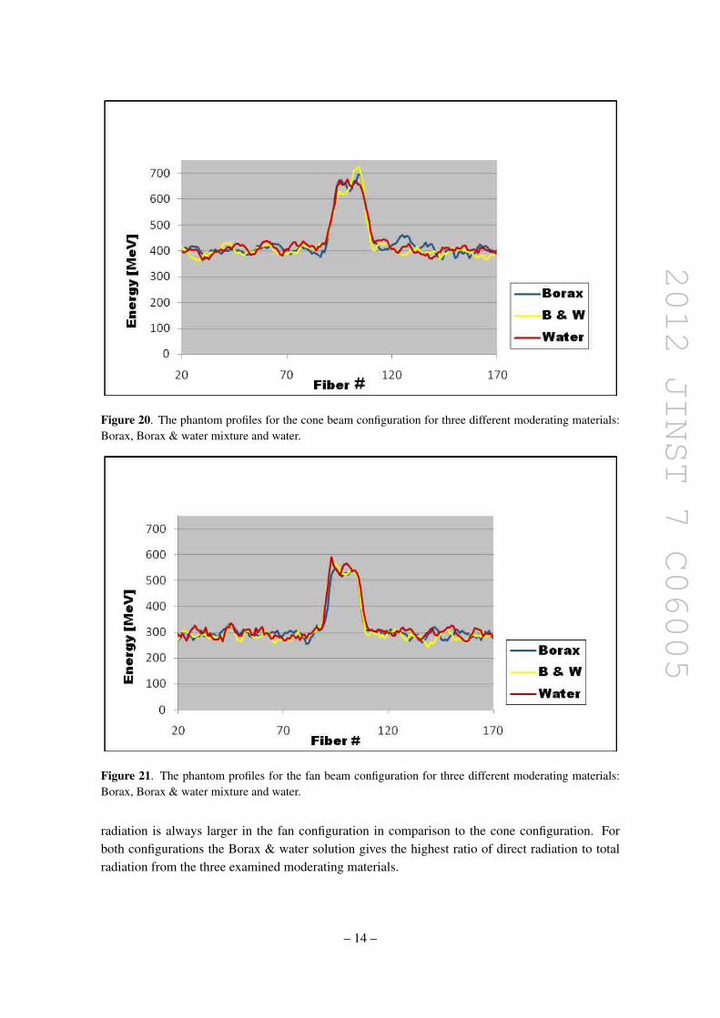
2012 JINST 7 C06005
Figure 20 The phantom profiles for the cone beam configuration for three different moderating materialsBorax Borax amp water mixture and water
Figure 21 The phantom profiles for the fan beam configuration for three different moderating materialsBorax Borax amp water mixture and water
radiation is always larger in the fan configuration in comparison to the cone configuration Forboth configurations the Borax amp water solution gives the highest ratio of direct radiation to totalradiation from the three examined moderating materials
ndash 14 ndash
2012 JINST 7 C06005
Table 4 The average ratios of the direct neutrons radiation energy contribution and the total detected radia-tion energy are shown for the fan and cone configurations for the three different moderating materials
Moderating materialsFAN Configura-tion
CONE configura-tion
DirectRadiation energy contribution []
BORAX 961plusmn17 895plusmn29BampW 970plusmn17 903plusmn27Water 942plusmn20 882plusmn29
Figure 22 The ratios of the direct neutrons radiation contribution and the total radiation detected in eachfiber for the fan configuration and for the three different moderating materials
5 Conclusions
The usage of the Borax and water mixture solution as the moderating material gives the best IQfrom the three different moderating materials which are studied The IQ measures are the SNRand the contrasts in the image The experimental results are consistent with the related simulationThe superiority of the Borax and water solution is for both configurations however comparing theconfigurations for each of the moderating materials we find better IQ for the fan configuration asexpected
ndash 15 ndash
2012 JINST 7 C06005
Figure 23 The ratios of the direct neutrons radiation contribution and the total radiation detected in eachfiber for the cone configuration and for the three different moderating materials
The surroundingsrsquo scatter is reduced meaningfully using a dedicated massive generator shieldwhich was built based on experimental and simulation studies and tested successfully for provenefficiency
As a consequence a dedicated collimator for a D-T generator 142 MeV Fast Neutrons isdeveloped for imaging purposes using the massive generator shield and the Borax and watermixture as the moderating material
References
[1] I Sabo-Napadensky and O Amir Reduction of scattering artifact in multislice CT MJ Flynn edProc SPIE 5745 (2005) 983
[2] J Star-Lack et al Efficient scatter correction using asymmetric kernels Proc SPIE 7258 (2009)72581Z
[3] BR Grogan The development of a parameterized scatter removal algorithm for nuclear materialsidentification system imaging PhD dissertation University of Tennessee Knoxville USA (2010)
[4] I Mor et al High spatial resolution fast-neutron imaging detectors for pulsed fast-neutrontransmission spectroscopy 2009 JINST 4 P05016
[5] American National Standards Institute Neutron radiation protection shielding mdash design principles andconsiderations for the choice of appropriate materials ISO 141522001 ANSI USA (2007)
ndash 16 ndash
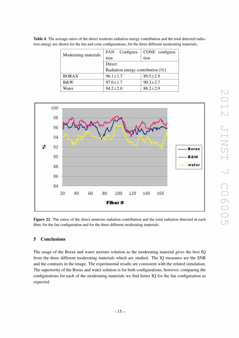
2012 JINST 7 C06005
Table 4 The average ratios of the direct neutrons radiation energy contribution and the total detected radia-tion energy are shown for the fan and cone configurations for the three different moderating materials
Moderating materialsFAN Configura-tion
CONE configura-tion
DirectRadiation energy contribution []
BORAX 961plusmn17 895plusmn29BampW 970plusmn17 903plusmn27Water 942plusmn20 882plusmn29
Figure 22 The ratios of the direct neutrons radiation contribution and the total radiation detected in eachfiber for the fan configuration and for the three different moderating materials
5 Conclusions
The usage of the Borax and water mixture solution as the moderating material gives the best IQfrom the three different moderating materials which are studied The IQ measures are the SNRand the contrasts in the image The experimental results are consistent with the related simulationThe superiority of the Borax and water solution is for both configurations however comparing theconfigurations for each of the moderating materials we find better IQ for the fan configuration asexpected
ndash 15 ndash
2012 JINST 7 C06005
Figure 23 The ratios of the direct neutrons radiation contribution and the total radiation detected in eachfiber for the cone configuration and for the three different moderating materials
The surroundingsrsquo scatter is reduced meaningfully using a dedicated massive generator shieldwhich was built based on experimental and simulation studies and tested successfully for provenefficiency
As a consequence a dedicated collimator for a D-T generator 142 MeV Fast Neutrons isdeveloped for imaging purposes using the massive generator shield and the Borax and watermixture as the moderating material
References
[1] I Sabo-Napadensky and O Amir Reduction of scattering artifact in multislice CT MJ Flynn edProc SPIE 5745 (2005) 983
[2] J Star-Lack et al Efficient scatter correction using asymmetric kernels Proc SPIE 7258 (2009)72581Z
[3] BR Grogan The development of a parameterized scatter removal algorithm for nuclear materialsidentification system imaging PhD dissertation University of Tennessee Knoxville USA (2010)
[4] I Mor et al High spatial resolution fast-neutron imaging detectors for pulsed fast-neutrontransmission spectroscopy 2009 JINST 4 P05016
[5] American National Standards Institute Neutron radiation protection shielding mdash design principles andconsiderations for the choice of appropriate materials ISO 141522001 ANSI USA (2007)
ndash 16 ndash
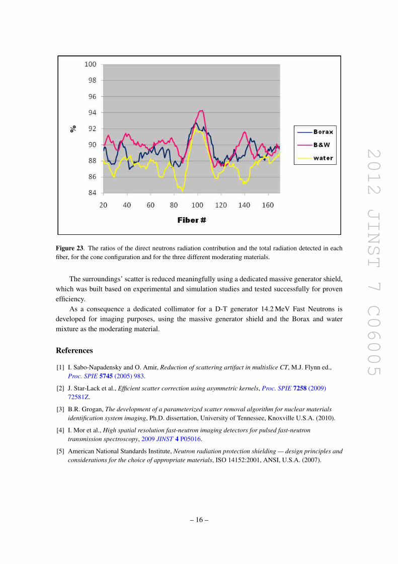
2012 JINST 7 C06005
Figure 23 The ratios of the direct neutrons radiation contribution and the total radiation detected in eachfiber for the cone configuration and for the three different moderating materials
The surroundingsrsquo scatter is reduced meaningfully using a dedicated massive generator shieldwhich was built based on experimental and simulation studies and tested successfully for provenefficiency
As a consequence a dedicated collimator for a D-T generator 142 MeV Fast Neutrons isdeveloped for imaging purposes using the massive generator shield and the Borax and watermixture as the moderating material
References
[1] I Sabo-Napadensky and O Amir Reduction of scattering artifact in multislice CT MJ Flynn edProc SPIE 5745 (2005) 983
[2] J Star-Lack et al Efficient scatter correction using asymmetric kernels Proc SPIE 7258 (2009)72581Z
[3] BR Grogan The development of a parameterized scatter removal algorithm for nuclear materialsidentification system imaging PhD dissertation University of Tennessee Knoxville USA (2010)
[4] I Mor et al High spatial resolution fast-neutron imaging detectors for pulsed fast-neutrontransmission spectroscopy 2009 JINST 4 P05016
[5] American National Standards Institute Neutron radiation protection shielding mdash design principles andconsiderations for the choice of appropriate materials ISO 141522001 ANSI USA (2007)
ndash 16 ndash