Embed Size (px)
Citation preview

COLLIMATOR DESIGN FOR THE NSNS ACCUMULATOR RING
H Ludewig E. Schmidt A. Aronson J. Walker M Todosow S. Mughabghab Brookhaven National Laboratory
P.O. Box 5000 Upton, New York 11973
(516) 344-2624
I. INTRODUCTION
Collimators are used to remove halo or off-momentum particles from the main proton beam. Off-momentum particles are removed by situating collimators in high dispersion areas of the beam. In addition to removing halo particles collimators will also act as shielding for the remainder of the accelerator structures. Thus, collimators reduce uncontrolled losses around the ring and reduce activation of the accelerator components.
Requirements and performance goals for the collimator are summaflzed * below:
1. 2.
3. Remove heat (1 kw), 4.
Halo proton attenuation by a factor of lo4, Minimize production of secondary radiation, and its subsequent leakage,
Mechanically compatible with ring operation (mitigate fatigue failures due to cyclic heating), and Minimize radiation damage and secondary activity.
5.
In order to meet these goals a selfshielding collimator configuration will be designed. An arrangement consisting of a layered structure will be considered. The initial layers (in the direction of the proton beam) are transparent to protons, and become progressively less transparent (blacker) with depth into the collimator. In addition, a high density (iron) shield will be added around this structure, particularly in the backward direction, to attenuate any reflected protons. The protons are stopped in the approximate center of the collimator, and thus the bulk of the secondary particles will also be generated there. Since these secondary particles are primarily produced isotropically their leakage path length will be maximized in
this manner (high probability of capture or attenuation). In the case of neutrons a black layer is included at each end in order to further minimize their leakage in the direction of the beam. This design will therefore minimize the activation of surrounding accelerator components.
II. CONCEPTUAL. DESIGN
A series of preliminary scoping studies were carried out using slabs of iron and tungsten. These calculations were carried out to understand the interactions of 1 GeV protons with possible collimator materials. Results from these calculations indicated that:
1.
2.
3.
4.
Back-scattered protons are distributed essentially isotropically, with a slight peak in the backward direction. Transmitted protons are highly peaked in the forward direction. N e W n production increases with increasing slab thickness, reaching a maximum at the stopping distance thickness. Intensity of transmitted neutrons increases with decreasing slab thickness until decreased production out-weighs increased slab transparency. Most neutrons exit at energies below 20 MeV, and Pion production is approximately 1/30 of neutron production (at the assumed 1 GeV proton beam energy).
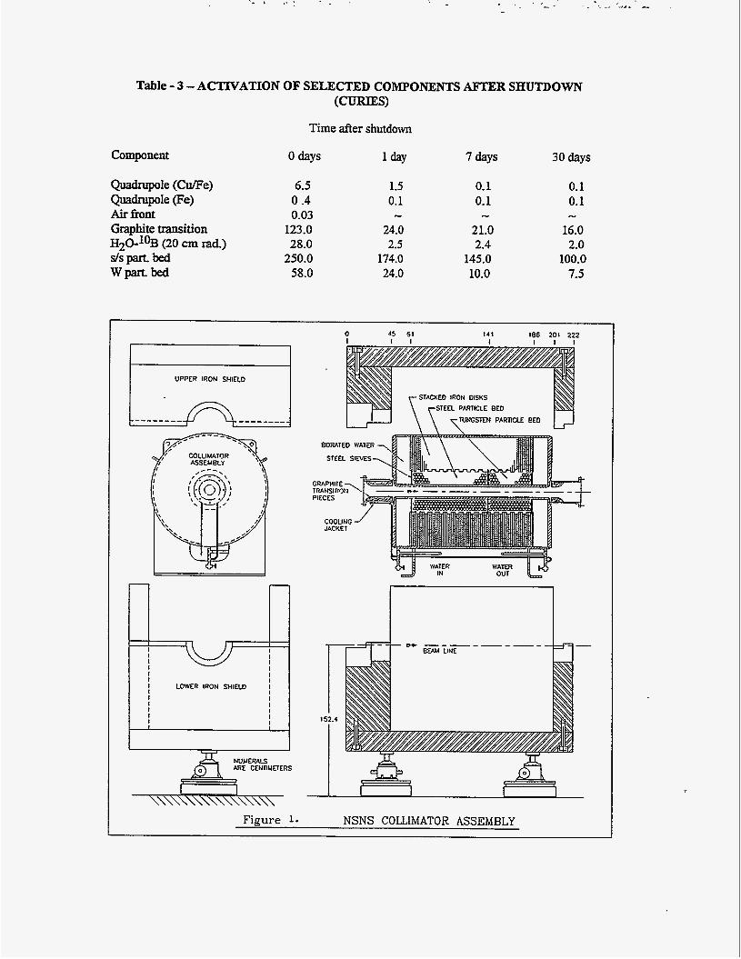
The conceptual design, based on the above results and ring constraints, is shown on Figure 1. The protons travel h m left to right, with the beam confined primarily to the inner diameter of the collimator. Halo particles are found between the collimator inner diameter and the beam tube inner diameter, and are assumed to pass into the collimator
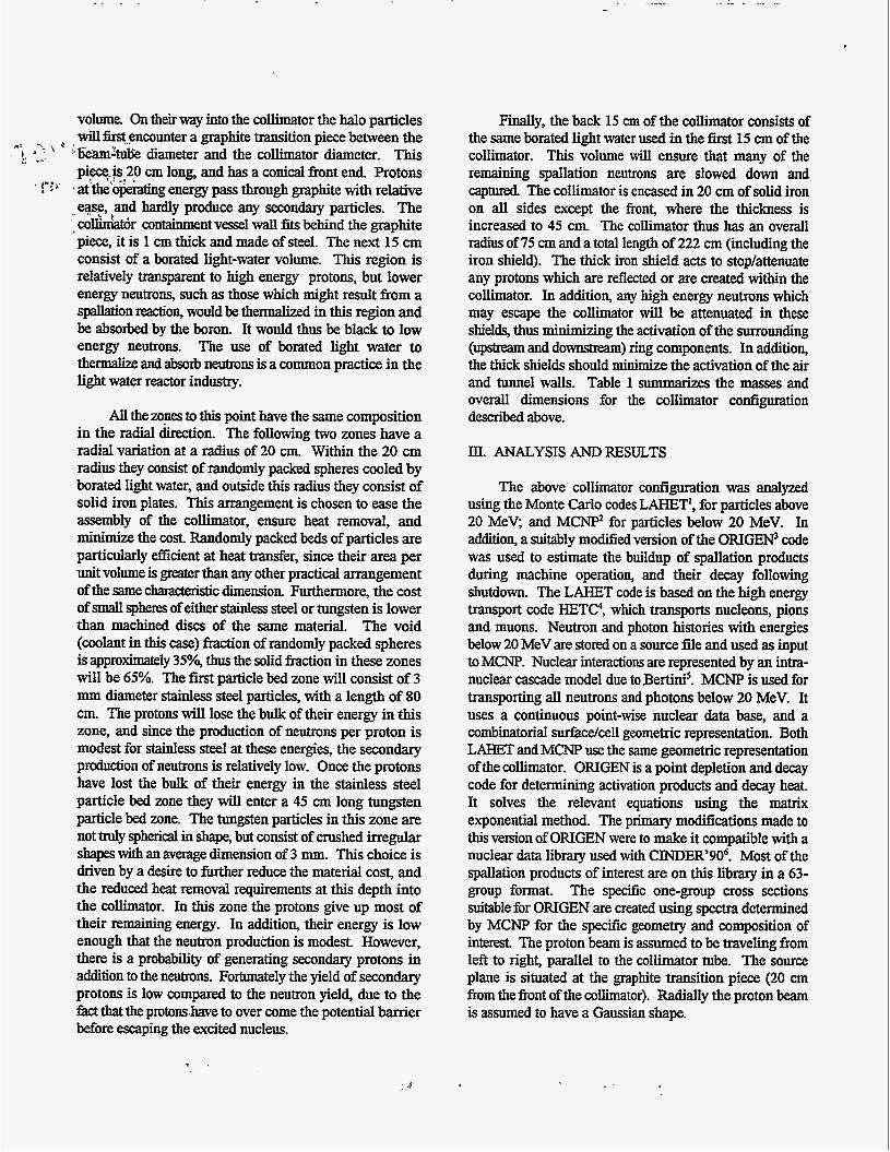
volume. On their way into the collimator the halo particles willkt-encounter a graphite transition piece between the 5eamh1lk diameter and the collimator diameter. This piece$s20 cm long, and has a conical front end. Protons atthe*o&ating energy pass through graphite with relative ease, and hardly produce any secondary particles. The
_. colkdatbr containment vessel wall fits behind the graphite piece, it is 1 cm thick and made of steel. The next 15 cm consist of a borated light-water volume. This region is relatively transparent to high energy protons, but lower energy neutrons, such as those which might result from a spaUation reaction, would be themalized in this region and be absorbed by the boron. It would thus be black to low energy neutrons. The use of borated light water to thermaliiz and absorb neutrons is a common practice in the light water reactor industry.
e- - 4
I Y . -1 t
v
All the zones to this point have the same composition in the radial direction. The following two zones have a radial variation at a radius of 20 cm. Within the 20 cm radius they consist of randomly packed spheres cooled by borated light water, and outside this radius they consist of solid iron plates. This arrangement is chosen to ease the assembly of the collimator, ensure heat removal, and minimize the cost. Randomly packed beds of particles are particularly efficient at heat W e r , since their area per unit volume is greater than any other practical arrangement OftheSamec- 'c dimension Furthermore, the cost of small sphem of either stainless steel or tungsten is lower than machined discs of the same material. The void (coolant in this case) W o n of randomly packed spheres is approximately 35%, thus the solid fraction in these zones will be 65%. The first particle bed zone will consist of 3 mm diameter stainless steel particles, with a length of 80 cm. The protons will lose the bulk of their energy in this zone, and since the production of neutrons per proton is modest for stainless steel at these energies, the secondary production of neutrons is relatively low. Once the protons have lost the bulk of their energy in the stainless steel particle bed zone they will enter a 45 cm long tungsten particle bed zone. The tungsten particles in this zone are not truly spherical in shape, but consist of crushed irregular shapes with an average dimension of 3 mm. This choice is driven by a desire to further reduce the material cost, and the reduced heat removal requirements at this depth into the collimator. In this zone the protons give up most of their remaining energy. In addition, their energy is low enough that the neutron produ6tion is modest. However, there is a probability of generating secondary protons in addition to the neutrons. Fortunately the yield of secondary protons is low compared to the neutron yield, due to the fact that the protons.have to over come the potential barrier before escaping the excited nucleus.
Finally, the back 15 cm of the collimator consists of the same borated light water used in the k s t 15 cm of the collimator. This volume wil l ensure that many of the remaining spallation neutrons are slowed down and captured The collimator is encased in 20 cm of solid iron on all sides except the front, where the thickness is increased to 45 cm. The collimator thus has an overall radius of 75 cm and a total length of 222 cm (including the iron shield). The thick iron shield acts to stop/attenuate any protons which are reflected or are created within the collimator. In addition, any high energy neutrons which may escape the collimator will be attenuated in these shields, thus minimizing the activation of the surrounding (upstream and downaream) ring components. In addition, the thick shields should minimize the activation of the air and tunnel walls. Table 1 Summarizes the masses and overall dimensions for the collimator configuration described above.
III. ANALYSIS AND RESULTS
The above collimator configuration was analyzed using the Monte Carlo codes LAHET', for particles above 20 MeV; and M C W for particles below 20 MeV. In addition, a suitably modified version of the ORIGW code was used to estimate the buildup of spallation products during machine operation, and their decay following shutdown. The LAHET code is based on the high energy transport code HETC?, which transports nucleons, pions and muons. Neutron and photon histories with energies below 20 MeV are stored on a source Ne and used as input to MCNP. Nuclear interactions are represented by an intra- nuclear cascade model due to Bertini'. MCNP is used for transporting all neutrons and photons below 20 MeV. It uses a continuous point-wise nuclear data base, and a combinatorial surface/cell geometric representation. Both LAHET and MCNP use the same geometric representation of the collimator. ORIGEN is a point depletion and decay code for determining activation products and decay heat. It solves the relevant equations using the matrix exponential method. The primary modifications made to this version of OIUGEN were to make it compatible with a nuclear data library used with CINDER'906. Most of the spallation products of interest are on this library in a 63- group format. The specific one-group cross sections suitable for ORIGEN are created using spectra determined by MCNP for the specific geometry and composition of interest The proton beam is assumed to be traveling from left to right, parallel to the collimator tube. The source plane is situated at the graphite transition piece (20 cm b m the front of the collimator). Radially the proton beam is assumed to have a Gaussian shape.


DISCLAIMER
This report was prepared as an account of work sponsored by an agency of the United States Government. Neither the United States Government nor any agency thereof, nor any of their employees, make any warranty, expm or implied, or assumes any legal liabili- ty or responsibility for the accuracy, completeness, or usefulness of any information, appa- ratus, product, or process disclosed, or represents that its use would not infringe privately owned rights. Reference herein to any specific commercial product, pn>cess, or service by trade name, trademark, manufacturer, or otherwise does not necessariiy comiitute or imply its endorsement, recommendation, or favoring by the United States Government or any agency thereof. The views and opinions of authors expressed herein do not necessar- ily state or reflect those of the United States Government or any agency thereof.
The performance of the above collimator design is shown in Table 2. These results show the backward (opposite to the direction of the proton beam) and forward (in the direction of the proton beam) proton currents in the halo zone of the beam (radius greater than 5 cm) at various axial positions along the collimator. It is seen that the halo constitutes a fiaction of 0.001 (surface 25.0 cm, forward direction). This fraction decreases monotonically to the back end of the collimator. In addition, the leakage out of the~ntendofthem~risalsoseentobevanishingly small (surface 0.0 cm, backwards direction). Within the collimator it is seen that .the proton current in the backward direction varies, with a maximum at the interface between the shield and the mimator tontainment vessel. The need for the thick iron shield is thus demonstrated. Thus, the proton leakage out of the back and front of the collimator meets the design goal set for it. Neutron currents at the same locations and directions as those for the proton currents are also shown in Table 2 (neutrons with energies above 20 MeV). It is seen that in the forward direction the neutron current increases initially and then decreases monotonically to a low value at the outer surface. In the backwards direction the current peaks at the interface between the k n t shield and the collimator body. Leakage out of the front face is also seen to be acceptably low.
The thick shield should minimize neutron leakage, which in tum will minimize the activation of the tunnel air. Activation levels can.be further reduced by venting the tunnel air. The only other activated material which can leave the collimator is the cooling water. Potentially 7Be and 3H'are formed and circulate in the coolant. E contained, the 3H should be undetectable, since it emits an electron upon decaying to 3He. However, the 7Be decays via a gamma ray (477.6 kev) and a half-life of 53.28 days. This poses a potential problem, particularly for maintenance w o k For the above reason the cooling water will be cooled in a closed loop via an intermediate heat exchanger. The maxiinum heat load from a collimator is 1 kW. Ifaternperatureriseof5"Cisassumed~in=3Oo C, and Tout=35"C) a flow rate of approximately 1.3(4)m3/s is required. This implies a moderate heat removal system for the design basis condition.
Estimates of the energy deposition in the collimator indicate the bulk of the power will be generated in the inner 20 cm of the front borated light water zone (9%), the front iron shield (lo%), the stainless steel particle bed (52%), and the graphite transition piece (20%). All these zones needtobecooledbythecoolingwatersystem. Thestainless steel particle bed zone is inside the collimator and is cooled by the borated water system. The.graphite transition piece and the iron shield will be cooled by a cooling jacket
positioned between them. They will thus be cooled on one surface by cooling water, and conduction within the body of the respective pieces. Preliminary estimates of the temperature in the two pieces indicate that they are well within their operating limits.
In addition to the estimates of energy deposition in bulk components, an estimate of the axial and radial variation of energy deposition was made in the collimator tube, and front shell. The energy deposition was found to be quite modest, with the xnaximurn ( 2 . 2 ~ 1 0 ~ W/m3) OcCuRing at the leading edge behind the graphite transition piece. Preliminary estimates of the temperature distribution were made, based on these energy deposition values. The tube and containment shell are subject to the most challenging thermal environment, since they are cooled on one surface, and the coolant flow pattern in the leading edge corner can be ambiguous if sufficient attention is not paid to channeling the coolant flow using appropriate vanes. Assuming a heat transfer coefficient of 350 W/m2- "C on the surfa~e the maximum temperature rise per pulse is estimated to be approximately 15"C, and the implied maximum thermal stress is estimated to be 4.0(7)N/m2. Thesevalues appeartobe within the operating limits of the containment shell material. However, it should be pointed out that the above estimates do not account for the cyclic nature of the beam, and the possible effects due to thermal- mechanical shock enhancement of the stresses.
The activation of selected zones within the collimator is shown in Table 3. The values shown on this table assume that the machine has operated for 180 days at full power (1 Mw, with 0.001 of the beam being captured in the collimator). Activation levels are shown for 1 day, 7 days, and 30 days following shutdown. It is seen that the quadrupole magnets have a low activation. The primary activation products being 51Cr, 54Mn, 56Mn, 55Fe, %e, 65Ni, 62Cu, and 66Cu. In the iron zones of the magnet structure the same activation products are important, except Cu and Ni. The dipole magnets behind the collimator have a vanishingly small amount of radioactive buildup. The energy spectrum due to decay gamma rays was found to peak in the energy range between 0.85 MeV and 1.25 MeV. The number of radioactive isotopes contributing to the overall activity is substantially reduced if only those isotopes are considered which decay by emitting a gamma ray with an energy between 0.85 MeV and 1.25 MeV. Thus, if only these isotopes are considered the activity in curies shown on Table 3 is reduced by approximately 50%. The activity of the solid components within the collimator is well shielded, and the gamma ray leakage out of the cylindrical surfaces of the shield is approximately six orders of magnitude below the source intensity.
Furthermore, the actfvity is contained within the collimator stmctm. Jffor some reason the radiation levels should be too high (for maintenance work) then it is possible to arrange for the placement of movable shields around the collimator. It is seen that the air activity is quite modest, and is initially dominated by argon activation, for longer times carbon is the dominant contributor. The stainless steel particle bed is the most activated part within the collimator.
Finally, it has been estimated that the number of electrons produced in the dlimator aperture tube is approximately 10-3/circulating proton. his estimate was made by carrying out a combined neutron, photon and electron transport calculation. Neutrons below 2OMeV and gamma rays due to xo decay and nuclear deexcitations were included in this calculation. These electrons are essentially isotropic in angular distribution, and have an energy spechum which peaks at 5.0 MeV. The effects of grazing protons due to a realistic proton beam have not been studied in great detail. However, off-setting the angle of the proton beam by approximately 3 mrad. relative to the collimator tube increased the number of electrons by about 25%.
Additional shielding mightbe required to minimize radiation levels during periods of maintenance. This will be accomplished by movable shielding blocks, which will be placed around the collimators should this be necessary-
ACKNOWLEDGMENTS
This work was performed under the auspices of the U. S. Department of Energy.
REFERENCES
RE. Prael and H. Lichtenstein, "User Guide to LCS: The LAHET Code System", Los Alamos National Laboratory, Los Alamos, NM, LA-UR-89-3014 (1989).
MCNP-A General Monte Carlo N-Particle Transport Code Version 4A, J.F. Breismeister, ed., Los Alamos
(1993). National Laboratory, LOS A I ~ ~ o s , NM, LA-12625-M
A.G. Croff, "ORIGEiV2 - A Revised and Updated Version of the Oak Ridge Isotope Generation and Depletion Code ", Oak Ridge National Laboratory, Oak Ridge, TN, ORNL-5621(1980).
Radiation Shielding Information Center, "HETC Monte Carlo High-Energy Nucleon-Meson Transport Code", Report CCC-178, Oak Ridge National Laboratory, Oak Ridge, TN, (1977).
H.W. Bertini, Phys. Rev. 188 (1969), p. 1711.
W. B. Wilson, 'fAccelerator Transmutation Studies at LosAlamos with LAHET, MCNP, and CINDER'90ff, Los Alamos National Laboratory, NM, LA-UR-93- 3080, (1993).
Research on the NSNS is sponsored by the Division of Material. Sciences, U. S. Department of Energy, under contract number DE-ACO596OR224.64 with Lockheed Martin Energy Research Corporation for Oak Ridge National Laboratory.
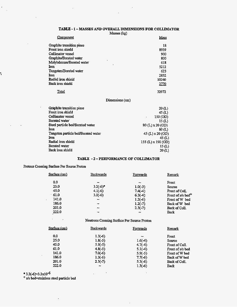
TABU3 - 1 - MASSES AND OVERALL DIMENSIONS FOR COLLIMATOR 0%)
Commnent Mass Graphite transition piece Front iron shield Collimator vessel Graphimoratedwater MolybdenudE3orated water Iron Tungsten/Borated water Iron Radial iron shield Back iron shield
18 8939 900 800 618
5212 623
2852 10240 2770
- Total 32972
Dimensions (an)
Gr8phite transition piece Front iron shield Collimator vessel Borated water’ Steel particle bedlsorated water Iron Tungsten particle bedlBorated water Iron Radial iron shield Boratedwater Back iron shield
20 (L) 45 (L)
. 150 (OD) 15
80 (L.) x 20 (OD) 80 Q
45 (L.) x 20 (OD) 45 (L)
155 (L) x 190 (OD) 15 Q 20 (L)
.TABLE - 2 -PERFORMANCE OF COLLIMATOR
F’rotons Crossing S d c e Per Source h t o n
surface (cm)
0.0 25.0 45.0
’ 61.0 . 141.0
186.0 201.0 222.0
surface fm)
0.0 25.0 45.0 61.0 141.0 186.0 201.0 222.0
Backwards Forwards
- 3.2(-6)* 4.1(-6) 3.0(-6) - - - -
- 1.0(-3) 7.4(4)
1.2(6) 6.3(-4)
1.2(-7) 2.3(-7) -
Neutrons Crossing Surface Per Source Proton
Backwards Forwards
1.3(-6) 1.8(-5)
4.8(-5) 5.9(-5)
7.0(-6) 1.3(-6) 2.3(-7) -
- 1.6(4) 4.7(4) 5.1(-4) 5.9(-5) 7.7(-6) 5.3(-6) 1.3(-6)
Remark
Front source Front of Coll. Front of s/s bed+ Front of W bed Back of W bed Back of Coll. Back
Remark
Front source Front of Coll. Front of s/s bed Front of W bed Back of W bed Back of Coll. Back
3.2(-6)=3.2x10⁶ + s/s bed=stainless steel particle bed
TabIe - 3 -ACTIVATION OF SELECTED COMPONENTS AFTER SHUTDOWN (CURIES)
Time after shutdown
Component 0 days 1 7 days 30 days
Quadrupole (Cfle) 6.5 1.5 0.1 0.1 Quadrupole 0 0.4 0.1 0.1 0.1 Air h n t 0.03 - - - Graphite transition 123.0 24.0 21.0 16.0 H20-1Og (20 cxu rad.) 28.0 2.5 2.4 2.0 dSpart.bed 250.0 174.0 145.0 100.0 W P a r t . M 58.0 24.0 10.0 7.5
n
0 45 61 141 166 201 222 I I I I I l l
UPPER IRON SHIELD I____/
I I I
I
I I
I I I
I LOWER IRON SHIELD I
I I
I I
I I
I I
t I
I I I
NUMERALS ARE CENTIMETERS
t 5
n
LJ \ \ \TUNGSTEN PARTICLE BED
EOFAlED
STEEL I
GRWlIlK - lRANSlllOI1 PIECES
COOLING JACKET
B+ B W LINE
152.4
I I I I I I
\\\\\\\\\\\\\\\\\ Figure 1- NSNS COLLIMATOR ASSEMBLY


![arXiv:2005.12071v1 [physics.acc-ph] 25 May 2020a) b) e-Block collimator Block collimator (hidden) Wedge collimator Figure 2: 3D CAD model of the three collimator device. (a) The block](https://img.pdfslide.us/doc/110x75/5f99e989b5ff3471203ba93f/arxiv200512071v1-25-may-2020-a-b-e-block-collimator-block-collimator-hidden.jpg)