Embed Size (px)
Citation preview
Railway Group Standard
GIRT7073
Issue Two
Date June 2018
Requirements for the Position of Infrastructure and for Defining and Maintaining Clearances
Synopsis
This document mandates requirements for positioning infrastructure and maintaining the position of track relative to infrastructure to achieve gauge compatibility with rolling stock.
[This document contains one or more pages which contain colour]
Copyright in the Railway Group Standards is owned by Rail Safety and Standards Board Limited. All rights are hereby reserved. No Railway Group Standard (in whole or in part) may be reproduced, stored in a retrieval system, or transmitted, in any form or means, without the prior written permission of Rail Safety and Standards Board Limited, or as expressly permitted by law.
RSSB members are granted copyright licence in accordance with the Constitution Agreement relating to Rail Safety and Standards Board Limited.
In circumstances where Rail Safety and Standards Board Limited has granted a particular person or organisation permission to copy extracts from Railway Group Standards, Rail Safety and Standards Board Limited accepts no responsibility for, nor any liability in connection with, the use of such extracts, or any claims arising therefrom. This disclaimer applies to all forms of media in which extracts from Railway Group Standards may be reproduced.
Published by: RSSB © Copyright 2018 Rail Safety and Standards Board Limited
Uncontrolled when printed Supersedes GIRT7073 Iss 1 with effect from 01/09/2018
Page 2 of 35 RSSB
Railway Group Standard
GIRT7073
Issue Two
Date June 2018
Requirements for the Position of Infrastructure and for Defining and Maintaining Clearances
Issue record
Issue Date Comments
One December 2015 Original document.
Supersedes GCRT5212 issue one Requirements for Defining and Maintaining Clearances.
Requirements out of scope of the RGS Code issue four are not taken forward in GIRT7073 issue one.
Lower sector infrastructure gauge replaces lower sector structure gauge.
Requirements for new infrastructure, alterations to reduce stepping distances at platforms and cross-winds clarified.
Two June 2018 Replaces issue one
Revisions to section 3.1.2.2, Categorisation of clearances, and Appendix A.1, Lower sector infrastructure gauge dimensions, to reflect changes to platform height requirements within GIRT7020, issue one (formerly contained within GIRT7016, issue five).
Cross-referencing to GIRT7016 (withdrawn) changed to GIRT7020 and RIS-7016-INS throughout.
Other editorial changes.
Revisions have been marked by a vertical black line in this issue.
Superseded documents
The following Railway Group Standard is superseded, either in whole or in part as indicated:
Superseded documents Sections superseded
Date when sections are superseded
GCRT5212 issue one Requirements for Defining and Maintaining Clearances
All 05 March 2016
GIRT7073 issue one Requirements for the Position of Infrastructure and for Defining and Maintaining Clearances
2.3.4; 2.3.5; 2.6.2.2; 3.1.2.2; 3.8.1.1; 4.4; 4.5; Appendix A.1; and Appendix B1.1
01 September 2018
Supply
The authoritative version of this document is available at https://www.rssb.co.uk/railway-group-standards. Enquiries on this document can be submitted through the RSSB Customer Self-Service Portal https://customer-portal.rssb.co.uk/
Uncontrolled when printed Supersedes GIRT7073 Iss 1 with effect from 01/09/2018
RSSB Page 3 of 35
Railway Group Standard
GIRT7073
Issue Two
Date June 2018
Requirements for the Position of Infrastructure and for Defining and Maintaining Clearances
Contents
Section Description Page
Part 1 Purpose and Introduction 5 1.1 Purpose 5 1.2 Introduction 5 1.3 Approval and authorisation of this document 6
Part 2 Requirements for New and Altered Infrastructure 7 2.1 Introduction to the requirements for new infrastructure 7 2.2 Requirements for new infrastructure for the upper sector 7 2.3 Lower sector infrastructure gauge (LSIG) for new infrastructure 8 2.4 Particular requirements for equipment in LSIG 8 2.5 Track intervals for new infrastructure 9 2.6 Alterations to existing infrastructure 9
Part 3 Management of Clearances 10 3.1 Categorisation of clearances 10 3.2 Calculation of clearances (method of calculation) 11 3.3 Track tolerances 12 3.4 Adjustment for cross-wind 14 3.5 Track quality data – for dynamic analysis 14 3.6 Determining the relative positions of tracks and structures 14 3.7 Data to be provided to railway undertakings (RUs) and their suppliers 16 3.8 Exceptional loads 17
Part 4 Application of this Document 18 4.1 Scope 18 4.2 Exclusions from scope 18 4.3 General compliance date 18 4.4 Exceptions to general compliance date 18 4.5 Deviations 18 4.6 Health and safety responsibilities 19
Appendices Appendix A Lower Sector Infrastructure Gauge 20 Appendix B Position of the Platform Edge 29
Tables Table 1 Equipment in LSIG 8 Table 2 Clearances in the upper sector to structures and between vehicles 10 Table 3 Clearances in the lower sector to structures and between vehicles 11 Table 4 Allowance for variation in lateral alignment 13 Table 5 Allowance for variation in vertical alignment 13 Table 6 Allowance for variation in cross-level 13 Table 7 Allowance for sidewear 14 Table B.1 Platform offset for standard case 29 Table B.2 Platform offset for selected radii for Class 373 case 30 Table B.3 Platform offset (inside of curved track) for selected radii for 2.6 m wide
containers 30
Uncontrolled when printed Supersedes GIRT7073 Iss 1 with effect from 01/09/2018

Page 4 of 35 RSSB
Railway Group Standard
GIRT7073
Issue Two
Date June 2018
Requirements for the Position of Infrastructure and for Defining and Maintaining Clearances
Figures
Figure A.1 LSIG – Area available for all infrastructure (not to scale) 21 Figure A.2 LSIG − Items intended for close proximity (not to scale) 22 Figure A.3 Position of conductor rail (not to scale) 23 Figure A.4 Position of conductor rail guard boarding (not to scale) 24 Figure A.5 Position of APC magnets (not to scale) 25 Figure A.6 Position of mechanical trainstops (not to scale) 26 Figure A.7 Position of tripcock tester (not to scale) 27 Figure B.1 Example of lower sector infrastructure gauge applied to a standard platform
adjacent to canted track (not to scale) 29
Definitions 31 References 35
Uncontrolled when printed Supersedes GIRT7073 Iss 1 with effect from 01/09/2018
RSSB Page 5 of 35
Railway Group Standard
GIRT7073
Issue Two
Date June 2018
Requirements for the Position of Infrastructure and for Defining and Maintaining Clearances
Part 1 Purpose and Introduction
1.1 Purpose
1.1.1 This document mandates requirements for positioning infrastructure and maintaining the position of track relative to infrastructure to achieve gauge compatibility with rolling stock.
1.2 Introduction
1.2.1 Background
1.2.1.1 The gauging principles set out in GIRT7073, GERT8273 and GMRT2173 are based upon a requirement for maintaining adequate clearances between the vehicle and adjacent structures, and maintaining adequate passing clearances between the vehicle and other vehicles operating on adjacent tracks.
1.2.1.2 The prime requirement is that there are always to be positive clearances between rolling stock and rolling stock, or rolling stock and infrastructure (excluding items designed to be in contact). In order to provide this, the documents set out in 1.2.1.1 mandate control measures which become progressively more stringent as clearances decrease. Thus, where large clearances exist, few control measures are required. Where small clearances exist, controls are required to maintain adequate clearances. Clearances are categorised as normal, reduced or special reduced.
1.2.2 Related requirements in other documents
1.2.2.1 The following Railway Group Standards (RGSs) contain requirements that are relevant to the scope of this document:
a) GERT8073 Requirements for the Application of Standard Vehicle Gauges − this document defines standard vehicle gauges and the associated application rules for rolling stock and for infrastructure. GERT8073 defines lower sector vehicle gauge (LSVG).
b) GERT8273 Assessment of Compatibility of Rolling Stock and Infrastructure - Gauging and Stepping Distances − this document sets out specific requirements and responsibilities for the assessment of gauge compatibility and stepping distances between rolling stock and infrastructure.
c) GIRT7020 GB Requirements for Platform Height, Platform Offset and Platform Width − this document sets GB requirements in scope of National Technical Rules for platform height, platform offset and platform width
d) GMRT2173 Requirements for the Size of Vehicles and Position of Equipment − this document sets out the methods of determining, and the requirements for maintaining, the swept envelope of rail vehicles. It sets out the format of the prescribed parameters for defining the size of railway vehicles and sets out particular requirements for components required to interface with the infrastructure.
e) GLRT1210 AC Energy Subsystem and Interfaces to Rolling Stock Subsystem − this document sets out the requirements for the AC energy system and the interfaces to rolling stock operating over the AC electrified railway.
f) GLRT1212 DC Conductor Rail Energy Subsystem and Interfaces to Rolling Stock Subsystem − this document defines the requirements for the DC conductor rail energy subsystem and the interfaces to rolling stock operating over the DC electrified railway.
Uncontrolled when printed Supersedes GIRT7073 Iss 1 with effect from 01/09/2018
Page 6 of 35 RSSB
Railway Group Standard
GIRT7073
Issue Two
Date June 2018
Requirements for the Position of Infrastructure and for Defining and Maintaining Clearances
g) GERT8025 Electrical Protective Provisions for Electrified Lines – this
document sets out provisions for electrical clearances for third rail electrified lines.
1.2.3 Supporting documents
1.2.3.1 The following Railway Group documents support this RGS:
a) GEGN8573 Guidance on Gauging − this document provides information and advisory material in support of the application of the various RGSs covering gauging. It also provides background material on the original derivation of the vehicle gauges in common use.
b) RIS-2773-RST Format for Vehicle Gauging Data − this document provides a standard format for defining the swept envelope of a vehicle for the purposes of compatibility assessment when undertaking absolute or comparative gauging. The data can also be used for the purposes of assessment against standard dynamic vehicle gauges.
c) RIS-8270-RST Route Level Assessment of Technical Compatibility between Vehicles and Infrastructure – this document sets out requirements and responsibilities for the assessment of technical compatibility at route level for vehicles and infrastructure.
d) RIS-7016-INS Interface between Station Platforms, Track, Trains and Buffer Stops – this document sets out requirements for the design and maintenance of station platforms for their safe interface with trains, track and buffer stops.
1.3 Approval and authorisation of this document
1.3.1 The content of this document was approved by Infrastructure Standards Committee (INS SC) on 07 March 2018.
1.3.2 This document was authorised by RSSB on 27 April 2018.
Uncontrolled when printed Supersedes GIRT7073 Iss 1 with effect from 01/09/2018
RSSB Page 7 of 35
Railway Group Standard
GIRT7073
Issue Two
Date June 2018
Requirements for the Position of Infrastructure and for Defining and Maintaining Clearances
Part 2 Requirements for New and Altered Infrastructure
2.1 Introduction to the requirements for new infrastructure
2.1.1 The Infrastructure TSI (2014) sets out requirements for gauge included in the relevant category of line. There is a Great Britain (GB) specific case that permits the use of National Rules for all categories of line, except category P1, a new dedicated high speed line.
2.1.2 Requirements for gauge clearance are related to either the upper sector or lower sector. The boundary between upper sector and lower sector is considered to be 1100 mm above rail level. Part 3 sets out the framework for clearances related to each sector.
2.2 Requirements for new infrastructure for the upper sector
2.2.1 Requirements for new infrastructure on a new railway line
2.2.1.1 New infrastructure on a new railway line shall be designed to accommodate:
a) The installation of overhead line equipment.
b) At least normal clearances in the upper sector to all standard vehicle gauges in GERT8073.
c) At least normal clearances in the upper sector to all types of rolling stock which the infrastructure manager (IM) may reasonably foresee using the route in future.
d) Access for staff (for example, lineside access routes and cess walkways).
2.2.1.2 Guidance on factors to be taken into account when determining clearances to allow space for overhead line equipment and access for staff is given in GEGN8573.
2.2.1.3 Requirements for overhead line equipment construction and electrical clearances are set out in GLRT1210.
2.2.1.4 The required clearances shall be calculated in accordance with 3.2.
2.2.2 Requirements for new infrastructure on an existing section of railway
2.2.2.1 New infrastructure on an existing section of railway shall be designed to provide at least normal clearances in the upper sector (see 3.1.2) to all types of rolling stock that use the route or have a statement of compatibility for the route involved.
2.2.2.2 New infrastructure shall be designed to accommodate the installation of overhead line equipment.
2.2.2.3 Guidance on factors to be taken into account when determining clearances to allow space for infrastructure systems (for example signalling and electrification systems) and access for staff is given in GEGN8573.
2.2.2.4 Requirements for overhead line equipment construction and electrical clearances are set out in GLRT1210.
2.2.2.5 The required clearances shall be calculated in accordance with 3.2.
Uncontrolled when printed Supersedes GIRT7073 Iss 1 with effect from 01/09/2018
Page 8 of 35 RSSB
Railway Group Standard
GIRT7073
Issue Two
Date June 2018
Requirements for the Position of Infrastructure and for Defining and Maintaining Clearances
2.2.3 Additional clearances at vehicle window level for new infrastructure
2.2.3.1 The following clearances shall be provided at the level of opening vehicle windows between 2000 mm and 3000 mm above the plane of the rails:
a) 450 mm where passenger vehicles operate with opening windows allowing passengers to lean out.
b) 250 mm where vehicles operate with opening windows for the use of train crew.
2.3 Lower sector infrastructure gauge (LSIG) for new infrastructure
2.3.1 New infrastructure shall not intrude inside the LSIG, as set out in Appendix A.1.
2.3.2 New track shall be positioned to ensure adjacent infrastructure does not intrude inside LSIG, as set out in Appendix A.1.
2.3.3 When designing new infrastructure, allowance shall be made for construction tolerances to ensure these requirements are met once the infrastructure has been built.
2.3.4 Requirements for platform height, and for the tapering of any discrepancy in height or alignment of the platform edge where a platform is altered or extended, are set out in GIRT7020.
2.3.5 Station platforms are necessarily close to trains to enable safe boarding and alighting. Additional requirements for platforms, including stepping distances, are set out in RIS-7016-INS. Requirements for footsteps for passenger use on new trains are set out in GMRT2173.
2.4 Particular requirements for equipment in LSIG
2.4.1 Certain items of equipment have to be in close proximity to rolling stock for system compatibility. The equipment set out in Table 1 shall be positioned as shown in the appendices.
Equipment Appendix
Conductor rails A.2
Conductor rail guard boarding A.3
Automatic power control (APC) magnets A.4
Mechanical trainstops A.5
Tripcock testers A.6
Automatic warning system (AWS) magnets A.7
Treadle actuating arms A.8
Table 1 Equipment in LSIG
Uncontrolled when printed Supersedes GIRT7073 Iss 1 with effect from 01/09/2018
RSSB Page 9 of 35
Railway Group Standard
GIRT7073
Issue Two
Date June 2018
Requirements for the Position of Infrastructure and for Defining and Maintaining Clearances
2.5 Track intervals for new infrastructure
2.5.1 For each section of track the track intervals to be used for new infrastructure shall take into account:
a) The requirement to provide normal clearances, as set out in 2.2.
b) Where necessary, the requirement to provide additional clearances for opening windows, as set out in 2.2.
c) If required, the space needed for trackside equipment, for example, signals and speed signs.
2.6 Alterations to existing infrastructure
2.6.1 Alterations other than to permit the passage of larger rail vehicles
2.6.1.1 Where existing infrastructure conforms to LSIG, any alterations shall not intrude inside LSIG.
2.6.1.2 When existing infrastructure is altered for reasons other than to permit the passage of larger rail vehicles, the alteration shall be designed so that the gauge capability in terms of standard vehicle gauges and vehicle classes is maintained.
2.6.2 Alterations to reduce stepping distances at platforms
2.6.2.1 It is permissible for platforms to be altered to reduce stepping distances by making clearances smaller to vehicles that use the route, or have a statement of compatibility for the route involved, provided the control measures appropriate to the resulting clearance category, for example, reduced clearance, are implemented.
2.6.2.2 Requirements for the altering of platforms relative to adjacent track are set out in RIS-7016-INS.
2.6.2.3 Requirements for the assessment of platform stepping distances if a change is made to the platform edge are set out in GERT8273.
2.6.3 Alterations to permit the passage of vehicles with a larger swept envelope
2.6.3.1 When existing infrastructure is altered to permit the passage of vehicles with a larger swept envelope, it is permissible for the alteration to be limited to that which is sufficient to allow the passage of the vehicle with a larger swept envelope, provided the control measures appropriate to the resulting clearance category (see 3.1), for example, reduced clearance, are implemented.
Uncontrolled when printed Supersedes GIRT7073 Iss 1 with effect from 01/09/2018
Page 10 of 35 RSSB
Railway Group Standard
GIRT7073
Issue Two
Date June 2018
Requirements for the Position of Infrastructure and for Defining and Maintaining Clearances
Part 3 Management of Clearances
3.1 Categorisation of clearances
3.1.1 Application of clearances
3.1.1.1 For both upper sector and lower sector, a minimum clearance between the swept envelope / gauge of a vehicle and the infrastructure and / or swept envelope / gauge of a vehicle on an adjacent track shall be calculated.
3.1.1.2 Clearances shall be calculated under conditions leading to the generation of that minimum clearance.
3.1.1.3 Clearances are to be determined by the consideration of the aggregation of all system tolerances and allowances (track, structure and swept envelope) together with the application of vehicle dynamic movements, taking account of measurement accuracies.
3.1.1.4 Where clearances are being calculated in the upper sector / lower sector boundary area (for example, the infrastructure is in the lower sector and the vehicle step height is in the upper sector), the categorisation of clearance (i.e. normal, reduced or special) shall be related to the vehicle or standard vehicle gauge.
3.1.2 Categorisation of clearances
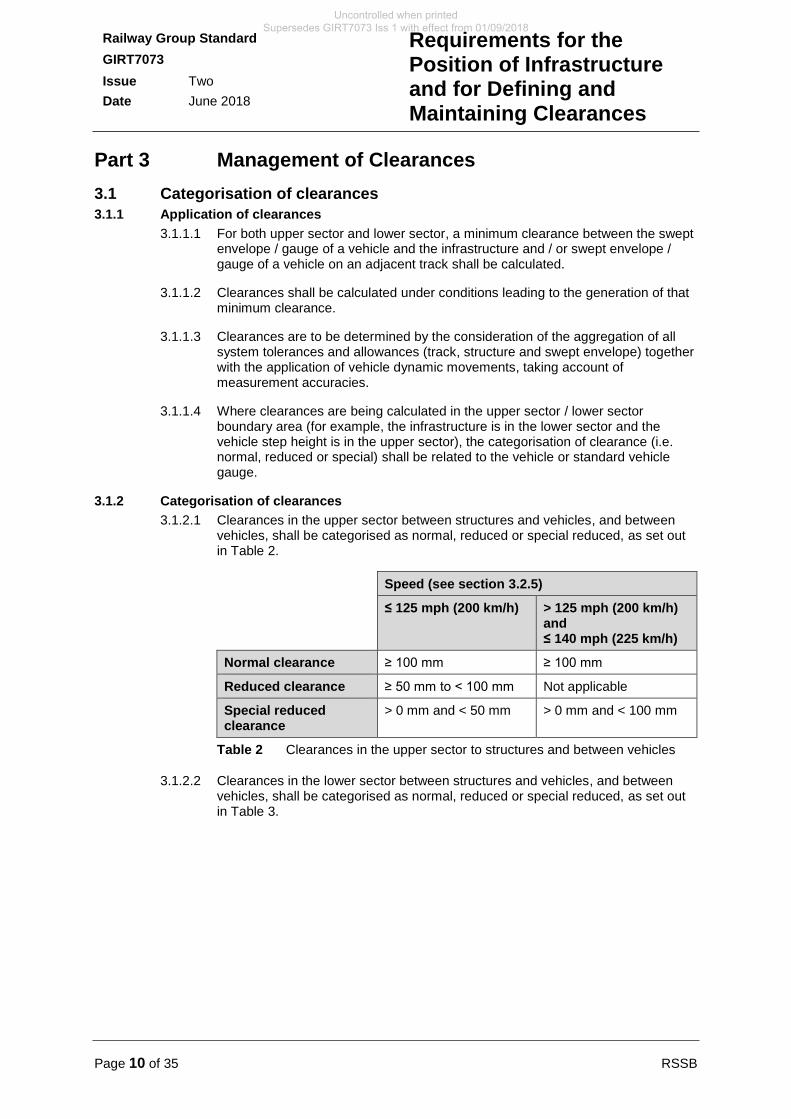
3.1.2.1 Clearances in the upper sector between structures and vehicles, and between vehicles, shall be categorised as normal, reduced or special reduced, as set out in Table 2.
Speed (see section 3.2.5)
≤ 125 mph (200 km/h) > 125 mph (200 km/h) and ≤ 140 mph (225 km/h)
Normal clearance ≥ 100 mm ≥ 100 mm
Reduced clearance ≥ 50 mm to < 100 mm Not applicable
Special reduced clearance
> 0 mm and < 50 mm > 0 mm and < 100 mm
Table 2 Clearances in the upper sector to structures and between vehicles
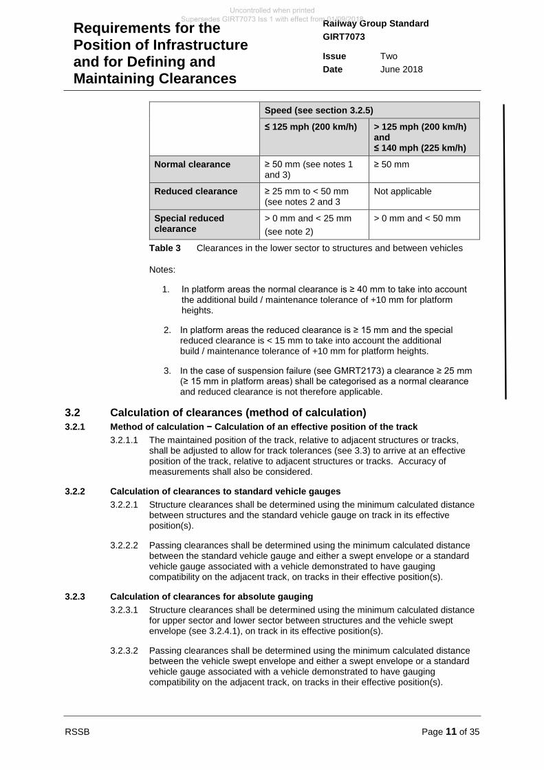
3.1.2.2 Clearances in the lower sector between structures and vehicles, and between vehicles, shall be categorised as normal, reduced or special reduced, as set out in Table 3.
Uncontrolled when printed Supersedes GIRT7073 Iss 1 with effect from 01/09/2018
RSSB Page 11 of 35
Railway Group Standard
GIRT7073
Issue Two
Date June 2018
Requirements for the Position of Infrastructure and for Defining and Maintaining Clearances
Speed (see section 3.2.5)
≤ 125 mph (200 km/h) > 125 mph (200 km/h) and ≤ 140 mph (225 km/h)
Normal clearance ≥ 50 mm (see notes 1 and 3)
≥ 50 mm
Reduced clearance ≥ 25 mm to < 50 mm (see notes 2 and 3
Not applicable
Special reduced clearance
> 0 mm and < 25 mm
(see note 2)
> 0 mm and < 50 mm
Table 3 Clearances in the lower sector to structures and between vehicles
Notes:
1. In platform areas the normal clearance is ≥ 40 mm to take into account the additional build / maintenance tolerance of +10 mm for platform heights.
2. In platform areas the reduced clearance is ≥ 15 mm and the special reduced clearance is < 15 mm to take into account the additional build / maintenance tolerance of +10 mm for platform heights.
3. In the case of suspension failure (see GMRT2173) a clearance ≥ 25 mm (≥ 15 mm in platform areas) shall be categorised as a normal clearance and reduced clearance is not therefore applicable.
3.2 Calculation of clearances (method of calculation)
3.2.1 Method of calculation − Calculation of an effective position of the track
3.2.1.1 The maintained position of the track, relative to adjacent structures or tracks, shall be adjusted to allow for track tolerances (see 3.3) to arrive at an effective position of the track, relative to adjacent structures or tracks. Accuracy of measurements shall also be considered.
3.2.2 Calculation of clearances to standard vehicle gauges
3.2.2.1 Structure clearances shall be determined using the minimum calculated distance between structures and the standard vehicle gauge on track in its effective position(s).
3.2.2.2 Passing clearances shall be determined using the minimum calculated distance between the standard vehicle gauge and either a swept envelope or a standard vehicle gauge associated with a vehicle demonstrated to have gauging compatibility on the adjacent track, on tracks in their effective position(s).
3.2.3 Calculation of clearances for absolute gauging
3.2.3.1 Structure clearances shall be determined using the minimum calculated distance for upper sector and lower sector between structures and the vehicle swept envelope (see 3.2.4.1), on track in its effective position(s).
3.2.3.2 Passing clearances shall be determined using the minimum calculated distance between the vehicle swept envelope and either a swept envelope or a standard vehicle gauge associated with a vehicle demonstrated to have gauging compatibility on the adjacent track, on tracks in their effective position(s).
Uncontrolled when printed Supersedes GIRT7073 Iss 1 with effect from 01/09/2018
Page 12 of 35 RSSB
Railway Group Standard
GIRT7073
Issue Two
Date June 2018
Requirements for the Position of Infrastructure and for Defining and Maintaining Clearances
3.2.4 Selection of relevant swept envelopes for absolute and comparative gauging
3.2.4.1 Requirements for vehicle swept envelopes to be determined are set out in GMRT2173, and include:
a) The full permissible range of operating speeds, cant excesses and cant deficiencies for which the vehicle has been designed.
b) Movements caused by dynamic inputs from track on the routes for which gauging compatibility is required.
c) The range of design and maintenance tolerances for the vehicle and its failure modes.
3.2.4.2 The relevant swept envelope shall be selected to suit the infrastructure at the location under consideration, taking the particular track parameters at the location into account (see 3.6).
3.2.4.3 For comparative gauging, the relevant swept envelopes applicable to the comparator vehicle shall be used.
3.2.5 Vehicle speeds to be used for calculation of clearances
3.2.5.1 The speeds to be used for the calculation of structure clearances and passing clearances shall be those that are associated with determining the minimum calculated clearance distances all around the vehicle (see 3.2.3). In the case of cant excess, intermediate speeds can be associated with minimum clearance on the inside of curves. In the case of cant deficiency, permissible or enhanced permissible speeds can be associated with minimum clearances on the outside of curves.
3.2.5.2 Where the permissible or enhanced permissible speed is higher than the maximum vehicle operating speed, it is permissible to use the maximum vehicle operating speed for the purpose of calculating clearances.
3.3 Track tolerances
3.3.1 Track fixity
3.3.1.1 The allowances for track tolerances to be made when calculating the effective position of the track in accordance with 3.2.1 depend on the fixity of the track. For this purpose, track fixity is classified as follows:
a) High track fixity – track with fixity equivalent to slab track.
b) Medium track fixity – track with fixity equivalent to undisturbed glued ballast.
c) Low track fixity – track with fixity equivalent to normal ballasted track.
d) Defined track fixity – track with a specific fixity no less restrained than track with low track fixity.
3.3.1.2 Changes to track fixity can be achieved by either construction works or through management and intervention to maintain the position of the track.
3.3.1.3 Track can have different fixities laterally and vertically and can exhibit asymmetric lateral fixity, for example, where track is strutted against a platform. Therefore, the track fixity appropriate to specific directions shall be used when calculating the effective position of the track.
Uncontrolled when printed Supersedes GIRT7073 Iss 1 with effect from 01/09/2018
RSSB Page 13 of 35
Railway Group Standard
GIRT7073
Issue Two
Date June 2018
Requirements for the Position of Infrastructure and for Defining and Maintaining Clearances
3.3.2 Allowances for track tolerance
3.3.2.1 The allowances for track tolerances set out in 3.3.3.1, 3.3.4.1, 3.3.5.1 and 3.3.6.1 shall be used when calculating the effective position of the track in accordance with 3.2.1.1.
3.3.2.2 The allowances for defined track fixity shall be determined on a case-by-case basis within the allowances set out in 3.3.3, 3.3.4, 3.3.5 and 3.3.6.
3.3.2.3 It is permissible for the allowances for track tolerances set out in 3.3.3.1, 3.3.4.1, 3.3.5.1 and 3.3.6.1 to be reduced by 25 % when calculating the clearance between a vehicle and vehicles on adjacent tracks.
3.3.2.4 At specific locations, for example on embankments subject to seasonal settlement, track tolerance values exceeding those set out in 3.3.3.1, 3.3.4.1, 3.3.5.1 and 3.3.6.1 can reasonably be expected. At such locations, the allowances for tolerances shall be assessed.
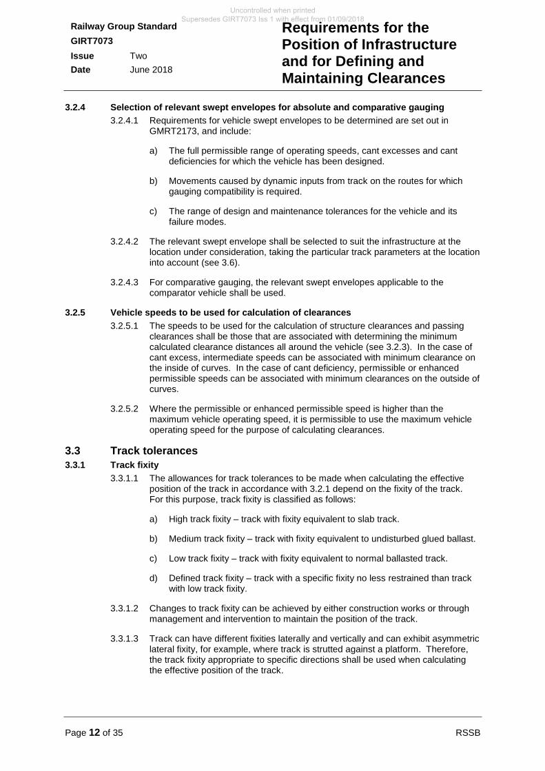
3.3.3 Allowance for variation in lateral alignment
3.3.3.1 The allowances set out in Table 4 shall be applied as a change in the position of the track, applied in the plane of the rails.
Track fixity Allowance
High track fixity NIL
Medium track fixity ± 15 mm
Low track fixity ± 25 mm
Table 4 Allowance for variation in lateral alignment
3.3.4 Allowance for variation in vertical alignment
3.3.4.1 The allowances set out in Table 5 shall be applied as a change in the position of the track, applied perpendicularly to the plane of the rails.
Track fixity Allowance
High track fixity NIL
Medium track fixity + 15 mm / - 10 mm
Low track fixity + 15 mm / -10 mm
Table 5 Allowance for variation in vertical alignment
3.3.5 Allowance for variation in cross-level
3.3.5.1 The allowances set out in Table 6 shall be applied as an increase or decrease in cant.
Track fixity Allowance
High track fixity NIL
Medium track fixity ± 7.5 mm
Low track fixity ± 10 mm
Table 6 Allowance for variation in cross-level
Uncontrolled when printed Supersedes GIRT7073 Iss 1 with effect from 01/09/2018
Page 14 of 35 RSSB
Railway Group Standard
GIRT7073
Issue Two
Date June 2018
Requirements for the Position of Infrastructure and for Defining and Maintaining Clearances
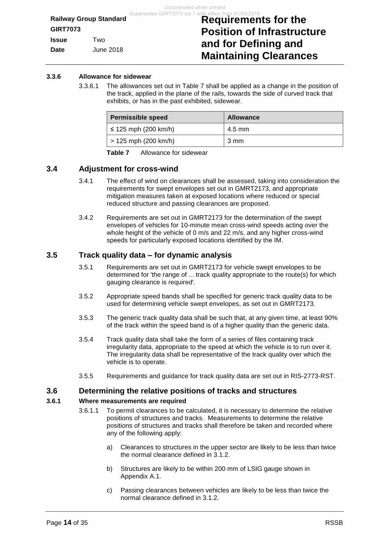
3.3.6 Allowance for sidewear
3.3.6.1 The allowances set out in Table 7 shall be applied as a change in the position of the track, applied in the plane of the rails, towards the side of curved track that exhibits, or has in the past exhibited, sidewear.
Permissible speed Allowance
≤ 125 mph (200 km/h) 4.5 mm
> 125 mph (200 km/h) 3 mm
Table 7 Allowance for sidewear
3.4 Adjustment for cross-wind
3.4.1 The effect of wind on clearances shall be assessed, taking into consideration the requirements for swept envelopes set out in GMRT2173, and appropriate mitigation measures taken at exposed locations where reduced or special reduced structure and passing clearances are proposed.
3.4.2 Requirements are set out in GMRT2173 for the determination of the swept envelopes of vehicles for 10-minute mean cross-wind speeds acting over the whole height of the vehicle of 0 m/s and 22 m/s, and any higher cross-wind speeds for particularly exposed locations identified by the IM.
3.5 Track quality data – for dynamic analysis
3.5.1 Requirements are set out in GMRT2173 for vehicle swept envelopes to be determined for 'the range of ... track quality appropriate to the route(s) for which gauging clearance is required'.
3.5.2 Appropriate speed bands shall be specified for generic track quality data to be used for determining vehicle swept envelopes, as set out in GMRT2173.
3.5.3 The generic track quality data shall be such that, at any given time, at least 90% of the track within the speed band is of a higher quality than the generic data.
3.5.4 Track quality data shall take the form of a series of files containing track irregularity data, appropriate to the speed at which the vehicle is to run over it. The irregularity data shall be representative of the track quality over which the vehicle is to operate.
3.5.5 Requirements and guidance for track quality data are set out in RIS-2773-RST.
3.6 Determining the relative positions of tracks and structures
3.6.1 Where measurements are required
3.6.1.1 To permit clearances to be calculated, it is necessary to determine the relative positions of structures and tracks. Measurements to determine the relative positions of structures and tracks shall therefore be taken and recorded where any of the following apply:
a) Clearances to structures in the upper sector are likely to be less than twice the normal clearance defined in 3.1.2.
b) Structures are likely to be within 200 mm of LSIG gauge shown in Appendix A.1.
c) Passing clearances between vehicles are likely to be less than twice the normal clearance defined in 3.1.2.
Uncontrolled when printed Supersedes GIRT7073 Iss 1 with effect from 01/09/2018
RSSB Page 15 of 35
Railway Group Standard
GIRT7073
Issue Two
Date June 2018
Requirements for the Position of Infrastructure and for Defining and Maintaining Clearances
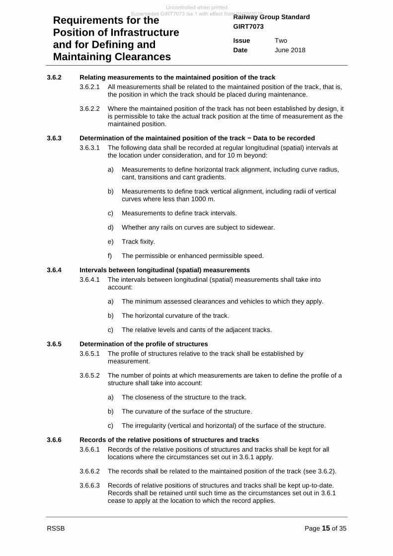
3.6.2 Relating measurements to the maintained position of the track
3.6.2.1 All measurements shall be related to the maintained position of the track, that is, the position in which the track should be placed during maintenance.
3.6.2.2 Where the maintained position of the track has not been established by design, it is permissible to take the actual track position at the time of measurement as the maintained position.
3.6.3 Determination of the maintained position of the track − Data to be recorded
3.6.3.1 The following data shall be recorded at regular longitudinal (spatial) intervals at the location under consideration, and for 10 m beyond:
a) Measurements to define horizontal track alignment, including curve radius, cant, transitions and cant gradients.
b) Measurements to define track vertical alignment, including radii of vertical curves where less than 1000 m.
c) Measurements to define track intervals.
d) Whether any rails on curves are subject to sidewear.
e) Track fixity.
f) The permissible or enhanced permissible speed.
3.6.4 Intervals between longitudinal (spatial) measurements
3.6.4.1 The intervals between longitudinal (spatial) measurements shall take into account:
a) The minimum assessed clearances and vehicles to which they apply.
b) The horizontal curvature of the track.
c) The relative levels and cants of the adjacent tracks.
3.6.5 Determination of the profile of structures
3.6.5.1 The profile of structures relative to the track shall be established by measurement.
3.6.5.2 The number of points at which measurements are taken to define the profile of a structure shall take into account:
a) The closeness of the structure to the track.
b) The curvature of the surface of the structure.
c) The irregularity (vertical and horizontal) of the surface of the structure.
3.6.6 Records of the relative positions of structures and tracks
3.6.6.1 Records of the relative positions of structures and tracks shall be kept for all locations where the circumstances set out in 3.6.1 apply.
3.6.6.2 The records shall be related to the maintained position of the track (see 3.6.2).
3.6.6.3 Records of relative positions of structures and tracks shall be kept up-to-date. Records shall be retained until such time as the circumstances set out in 3.6.1 cease to apply at the location to which the record applies.
Uncontrolled when printed Supersedes GIRT7073 Iss 1 with effect from 01/09/2018
Page 16 of 35 RSSB
Railway Group Standard
GIRT7073
Issue Two
Date June 2018
Requirements for the Position of Infrastructure and for Defining and Maintaining Clearances
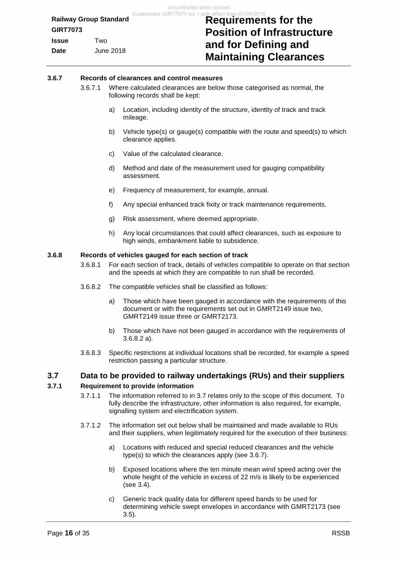
3.6.7 Records of clearances and control measures
3.6.7.1 Where calculated clearances are below those categorised as normal, the following records shall be kept:
a) Location, including identity of the structure, identity of track and track mileage.
b) Vehicle type(s) or gauge(s) compatible with the route and speed(s) to which clearance applies.
c) Value of the calculated clearance.
d) Method and date of the measurement used for gauging compatibility assessment.
e) Frequency of measurement, for example, annual.
f) Any special enhanced track fixity or track maintenance requirements.
g) Risk assessment, where deemed appropriate.
h) Any local circumstances that could affect clearances, such as exposure to high winds, embankment liable to subsidence.
3.6.8 Records of vehicles gauged for each section of track
3.6.8.1 For each section of track, details of vehicles compatible to operate on that section and the speeds at which they are compatible to run shall be recorded.
3.6.8.2 The compatible vehicles shall be classified as follows:
a) Those which have been gauged in accordance with the requirements of this document or with the requirements set out in GMRT2149 issue two, GMRT2149 issue three or GMRT2173.
b) Those which have not been gauged in accordance with the requirements of 3.6.8.2 a).
3.6.8.3 Specific restrictions at individual locations shall be recorded, for example a speed restriction passing a particular structure.
3.7 Data to be provided to railway undertakings (RUs) and their suppliers
3.7.1 Requirement to provide information
3.7.1.1 The information referred to in 3.7 relates only to the scope of this document. To fully describe the infrastructure, other information is also required, for example, signalling system and electrification system.
3.7.1.2 The information set out below shall be maintained and made available to RUs and their suppliers, when legitimately required for the execution of their business:
a) Locations with reduced and special reduced clearances and the vehicle type(s) to which the clearances apply (see 3.6.7).
b) Exposed locations where the ten minute mean wind speed acting over the whole height of the vehicle in excess of 22 m/s is likely to be experienced (see 3.4).
c) Generic track quality data for different speed bands to be used for determining vehicle swept envelopes in accordance with GMRT2173 (see 3.5).
Uncontrolled when printed Supersedes GIRT7073 Iss 1 with effect from 01/09/2018
RSSB Page 17 of 35
Railway Group Standard
GIRT7073
Issue Two
Date June 2018
Requirements for the Position of Infrastructure and for Defining and Maintaining Clearances
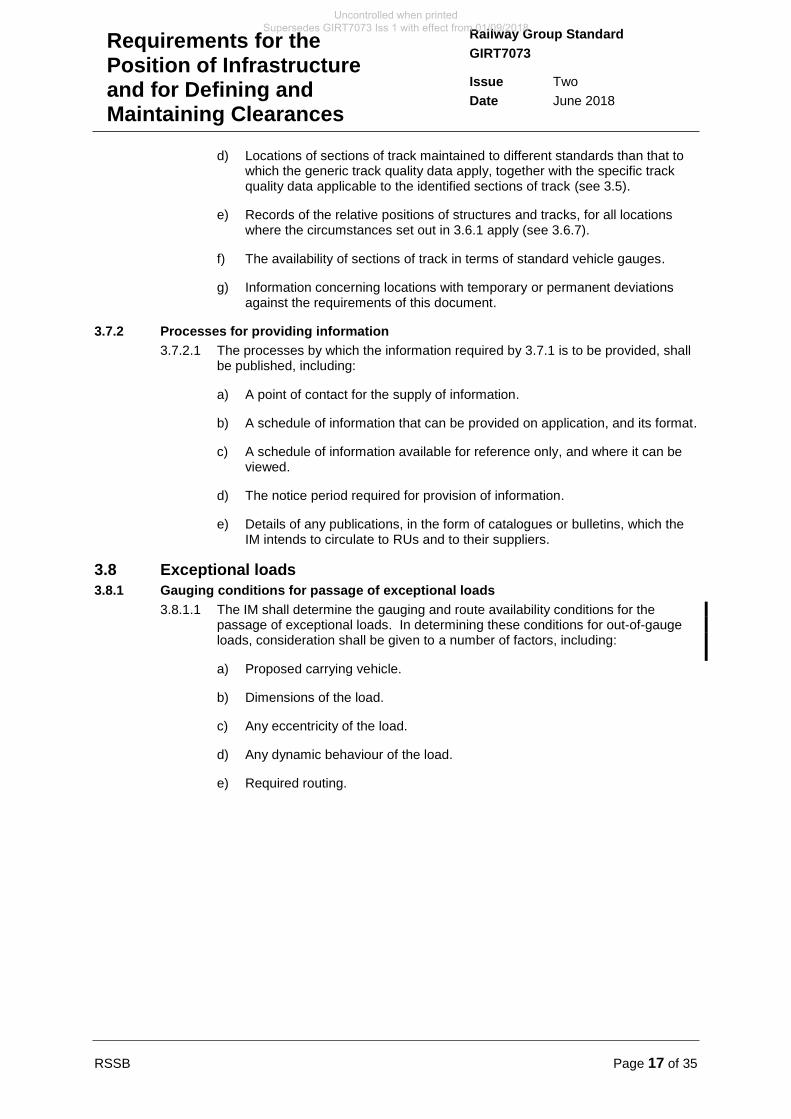
d) Locations of sections of track maintained to different standards than that to which the generic track quality data apply, together with the specific track quality data applicable to the identified sections of track (see 3.5).
e) Records of the relative positions of structures and tracks, for all locations where the circumstances set out in 3.6.1 apply (see 3.6.7).
f) The availability of sections of track in terms of standard vehicle gauges.
g) Information concerning locations with temporary or permanent deviations against the requirements of this document.
3.7.2 Processes for providing information
3.7.2.1 The processes by which the information required by 3.7.1 is to be provided, shall be published, including:
a) A point of contact for the supply of information.
b) A schedule of information that can be provided on application, and its format.
c) A schedule of information available for reference only, and where it can be viewed.
d) The notice period required for provision of information.
e) Details of any publications, in the form of catalogues or bulletins, which the IM intends to circulate to RUs and to their suppliers.
3.8 Exceptional loads
3.8.1 Gauging conditions for passage of exceptional loads
3.8.1.1 The IM shall determine the gauging and route availability conditions for the passage of exceptional loads. In determining these conditions for out-of-gauge loads, consideration shall be given to a number of factors, including:
a) Proposed carrying vehicle.
b) Dimensions of the load.
c) Any eccentricity of the load.
d) Any dynamic behaviour of the load.
e) Required routing.
Uncontrolled when printed Supersedes GIRT7073 Iss 1 with effect from 01/09/2018
Page 18 of 35 RSSB
Railway Group Standard
GIRT7073
Issue Two
Date June 2018
Requirements for the Position of Infrastructure and for Defining and Maintaining Clearances
Part 4 Application of this Document
4.1 Scope
4.1.1 The requirements of Part 2 of this document apply to all new infrastructure and alterations to existing infrastructure.
4.1.2 The requirements of Part 3 of this document apply to all existing infrastructure.
4.1.3 The requirements of this document apply to all work that affects the provision of adequate clearance between the vehicle and adjacent infrastructure, and maintaining clearance between the vehicle and other vehicles operating on adjacent tracks, whether new or alteration.
4.1.4 Compliance with the requirements of this document relating to inspection, maintenance and in-service condition of infrastructure is mandatory
4.1.5 Where it is known, or becomes known, that the position of existing infrastructure does not comply with the requirements of this document, action to bring them into compliance is required as follows:
a) When the position of existing infrastructure is modified.
b) When a track is renewed as a whole (for example rail, sleepers and ballast).
c) When any major component of a structure is replaced.
4.2 Exclusions from scope
4.2.1 There are no exclusions from the scope specified in 4.1.
4.3 General compliance date
4.3.1 This RGS comes into force and is to be complied with from 01 September 2018 except as specified in 4.4 of this document. Where the dates specified in 4.4 are later than the above date, this is to allow sufficient time to achieve compliance with the specified exceptions.
4.4 Exceptions to general compliance date
4.4.1 There are no exceptions to the general compliance date specified in 4.3 of this document.
4.4.2 The Office of Rail and Road can be contacted for clarification on the applicable requirements where a project seeking authorisation for placing into service is already underway when this document enters into force.
4.5 Deviations
4.5.1 Where it is considered not reasonably practicable to comply with the requirements of this document (including any requirement to comply with a TSI requirement referred to in the application of this document), permission to comply with a specified alternative should be sought in accordance with the deviation process set out in the Railway Group Standards (RGS) Code.
4.5.2 In the case where TSI compliance is required for a new, renewed or upgraded vehicle or structural subsystem, the derogation process to be followed is set out in the Railways (Interoperability) Regulations 2011 (as amended).
Uncontrolled when printed Supersedes GIRT7073 Iss 1 with effect from 01/09/2018
RSSB Page 19 of 35
Railway Group Standard
GIRT7073
Issue Two
Date June 2018
Requirements for the Position of Infrastructure and for Defining and Maintaining Clearances
4.6 Health and safety responsibilities
4.6.1 Users of documents published by RSSB are reminded of the need to consider their own responsibilities to ensure health and safety at work and their own duties under health and safety legislation. RSSB does not warrant that compliance with all or any documents published by RSSB is sufficient in itself to ensure safe systems of work or operation or to satisfy such responsibilities or duties.
Uncontrolled when printed Supersedes GIRT7073 Iss 1 with effect from 01/09/2018
Page 20 of 35 RSSB
Railway Group Standard
GIRT7073
Issue Two
Date June 2018
Requirements for the Position of Infrastructure and for Defining and Maintaining Clearances
Appendix A Lower Sector Infrastructure Gauge
The content of this Appendix is mandatory.
A.1 Lower sector infrastructure gauge dimensions
A.1.1 Lower sector infrastructure gauge outline
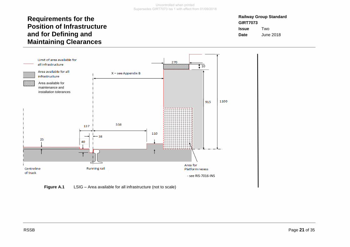
A.1.1.1 LSIG is set out in this Appendix as a series of diagrams and associated application rules and notes. Figure A.1 shows the area available for all infrastructure that do not need to be in close proximity for specific system functionality.
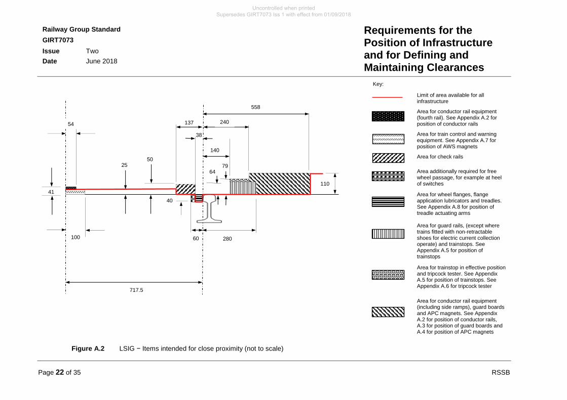
A.1.1.2 Figure A.2 shows the LSIG – items intended for close proximity as a semi-width, dimensioned with respect to track centre line and running edge. The semi-width gauge shall be applied symmetrically about the track centre line.
A.1.1.3 Figure A.3 shows the position of the conductor rail.
A.1.1.4 Sections A.2 to A.7 set out particular requirements for items of equipment that need to be positioned to interface with train-mounted equipment.
A.1.1.5 On tight radius curves where designed track gauge widening applies, the dimensions shall not be adjusted by the gauge widening value.
A.1.1.6 The following notes apply to Figures A.1 to A.7:
a) All lines are parallel to, or at right angles to, the plane of the rails.
b) All dimensions are measured relative to the maintained position of the track.
c) All dimensions are in millimetres.
d) Except for the area for wheel flanges, locations below the plane of the rails are available for infrastructure.
e) See Appendix B for the platform edge area and structures required to be close to the track.
f) The platform recess is to provide a space for a person to escape from a train if they fall off the platform and to provide access for emergency services for persons trapped between the train and the platform. It is permissible to use this space for discrete items of equipment that are required to be in the platform area, for example datum plates.
g) Items of equipment that are required to be in the lower sector should be positioned along the track, such that they do not create a conflict. For example, a gap in conductor rails should be installed to provide the clear space for a trainstop.
Uncontrolled when printed Supersedes GIRT7073 Iss 1 with effect from 01/09/2018
RSSB Page 21 of 35
Railway Group Standard
GIRT7073
Issue Two
Date June 2018
Requirements for the Position of Infrastructure and for Defining and Maintaining Clearances
Figure A.1 LSIG – Area available for all infrastructure (not to scale)
10
- see RIS-7016-INS
Area available for
maintenance and
installation tolerances
Uncontrolled when printed Supersedes GIRT7073 Iss 1 with effect from 01/09/2018
Page 22 of 35 RSSB
Railway Group Standard
GIRT7073
Issue Two
Date June 2018
Requirements for the Position of Infrastructure and for Defining and Maintaining Clearances
Figure A.2 LSIG − Items intended for close proximity (not to scale)
Limit of area available for all infrastructure
Area for conductor rail equipment (fourth rail). See Appendix A.2 for position of conductor rails
Area for train control and warning equipment. See Appendix A.7 for position of AWS magnets
Area for check rails
Area additionally required for free wheel passage, for example at heel of switches
Area for wheel flanges, flange application lubricators and treadles. See Appendix A.8 for position of treadle actuating arms
Area for guard rails, (except where trains fitted with non-retractable shoes for electric current collection operate) and trainstops. See Appendix A.5 for position of trainstops
Area for trainstop in effective position and tripcock tester. See Appendix A.5 for position of trainstops. See Appendix A.6 for tripcock tester
Area for conductor rail equipment (including side ramps), guard boards and APC magnets. See Appendix A.2 for position of conductor rails, A.3 for position of guard boards and A.4 for position of APC magnets
41
64 79
100
40
60
137
38
558
240
140
110
280
50 25
54
717.5
Key:
Uncontrolled when printed Supersedes GIRT7073 Iss 1 with effect from 01/09/2018
RSSB Page 23 of 35
Railway Group Standard
GIRT7073
Issue Two
Date June 2018
Requirements for the Position of Infrastructure and for Defining and Maintaining Clearances
A.2 Position of conductor rails
A.2.1 Position of conductor rails with respect to running edge
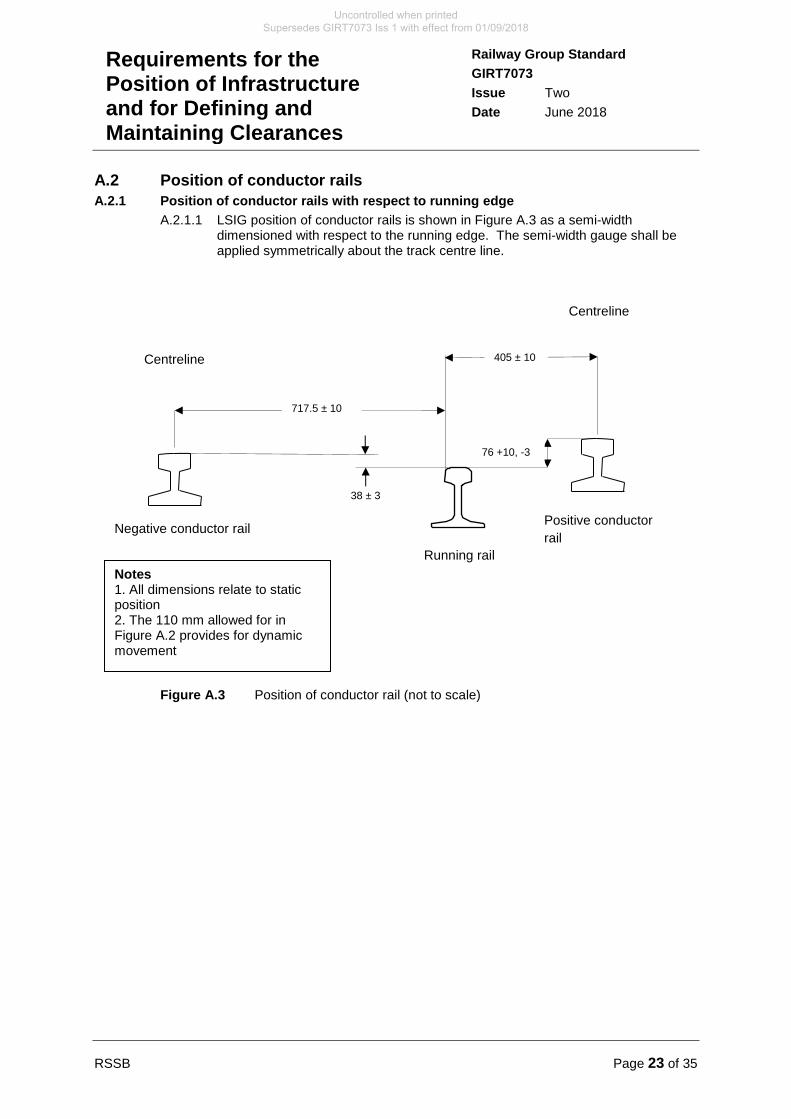
A.2.1.1 LSIG position of conductor rails is shown in Figure A.3 as a semi-width dimensioned with respect to the running edge. The semi-width gauge shall be applied symmetrically about the track centre line.
Figure A.3 Position of conductor rail (not to scale)
Negative conductor rail
Centreline
717.5 ± 10
38 ± 3
76 +10, -3
405 ± 10
Centreline
Positive conductor
rail
Notes 1. All dimensions relate to static position 2. The 110 mm allowed for in Figure A.2 provides for dynamic movement
Running rail
Uncontrolled when printed Supersedes GIRT7073 Iss 1 with effect from 01/09/2018
Page 24 of 35 RSSB
Railway Group Standard
GIRT7073
Issue Two
Date June 2018
Requirements for the Position of Infrastructure and for Defining and Maintaining Clearances
A.3 Position of conductor rail guard boarding
A.3.1 Position of conductor rail guard boarding with respect to running edge
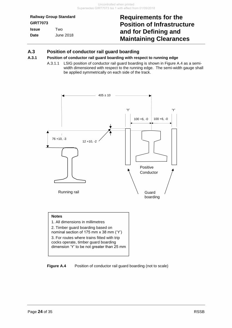
A.3.1.1 LSIG position of conductor rail guard boarding is shown in Figure A.4 as a semi-width dimensioned with respect to the running edge. The semi-width gauge shall be applied symmetrically on each side of the track.
Figure A.4 Position of conductor rail guard boarding (not to scale)
100 +6, -0
Notes
1. All dimensions in millimetres
2. Timber guard boarding based on nominal section of 175 mm x 38 mm (‘Y’)
3. For routes where trains fitted with trip cocks operate, timber guard boarding dimension ‘Y’ to be not greater than 25 mm
12 +10, -2
Positive
Conductor
Guard boarding
76 +10, -3
405 ± 10
100 +6, -0
‘Y’ ‘Y’
Running rail
Uncontrolled when printed Supersedes GIRT7073 Iss 1 with effect from 01/09/2018
RSSB Page 25 of 35
Railway Group Standard
GIRT7073
Issue Two
Date June 2018
Requirements for the Position of Infrastructure and for Defining and Maintaining Clearances
A.4 Position of APC magnets
A.4.1 Position of APC magnets with respect to running edge
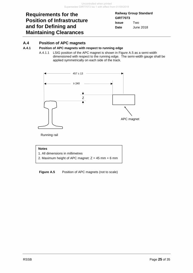
A.4.1.1 LSIG position of the APC magnet is shown in Figure A.5 as a semi-width dimensioned with respect to the running edge. The semi-width gauge shall be applied symmetrically on each side of the track.
Figure A.5 Position of APC magnets (not to scale)
Z
APC magnet
457 ± 13
≥ 240
Notes
1. All dimensions in millimetres
2. Maximum height of APC magnet: Z = 45 mm + 6 mm
Running rail
Uncontrolled when printed Supersedes GIRT7073 Iss 1 with effect from 01/09/2018
Page 26 of 35 RSSB
Railway Group Standard
GIRT7073
Issue Two
Date June 2018
Requirements for the Position of Infrastructure and for Defining and Maintaining Clearances
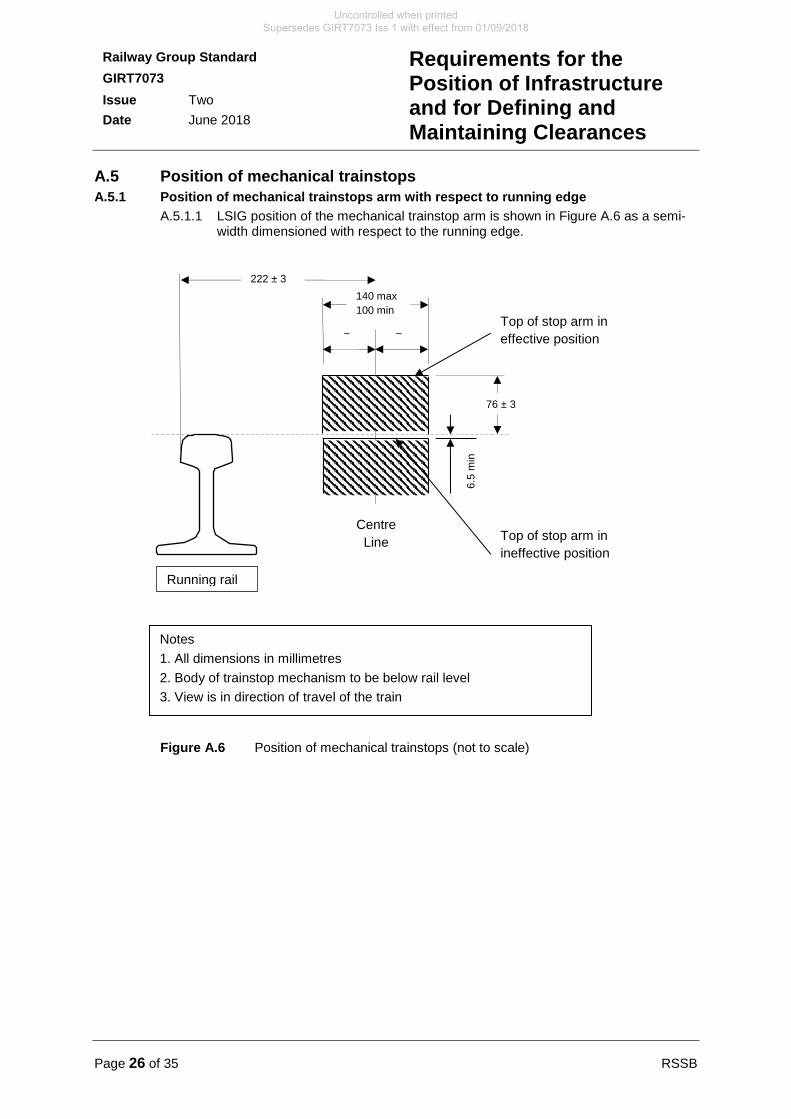
A.5 Position of mechanical trainstops
A.5.1 Position of mechanical trainstops arm with respect to running edge
A.5.1.1 LSIG position of the mechanical trainstop arm is shown in Figure A.6 as a semi-width dimensioned with respect to the running edge.
Figure A.6 Position of mechanical trainstops (not to scale)
222 ± 3
140 max
100 min
Notes
1. All dimensions in millimetres
2. Body of trainstop mechanism to be below rail level
3. View is in direction of travel of the train
~ ~ Top of stop arm in
effective position
Top of stop arm in
ineffective position
76 ± 3
6.5
min
Centre
Line
Running rail
Uncontrolled when printed Supersedes GIRT7073 Iss 1 with effect from 01/09/2018
RSSB Page 27 of 35
Railway Group Standard
GIRT7073
Issue Two
Date June 2018
Requirements for the Position of Infrastructure and for Defining and Maintaining Clearances
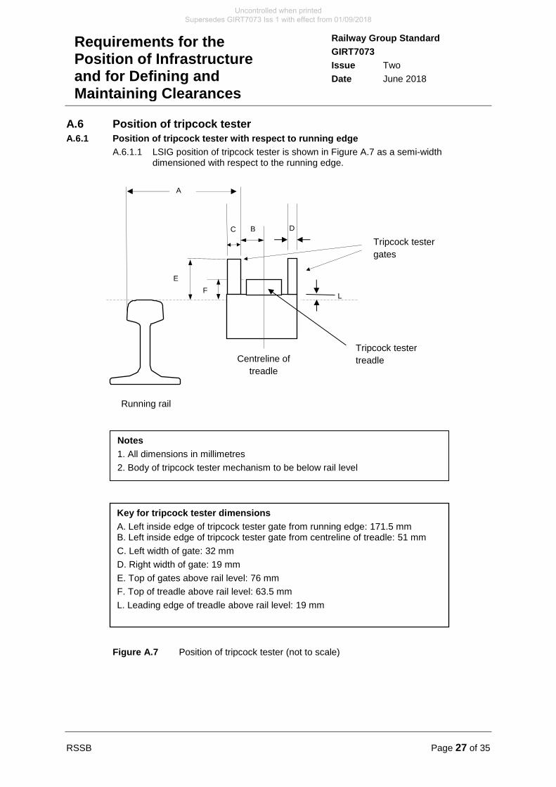
A.6 Position of tripcock tester
A.6.1 Position of tripcock tester with respect to running edge
A.6.1.1 LSIG position of tripcock tester is shown in Figure A.7 as a semi-width dimensioned with respect to the running edge.
Figure A.7 Position of tripcock tester (not to scale)
L
D C
A
Notes
1. All dimensions in millimetres
2. Body of tripcock tester mechanism to be below rail level
B
Tripcock tester
gates
Tripcock tester
treadle Centreline of
treadle
E
F
Key for tripcock tester dimensions
A. Left inside edge of tripcock tester gate from running edge: 171.5 mm B. Left inside edge of tripcock tester gate from centreline of treadle: 51 mm
C. Left width of gate: 32 mm
D. Right width of gate: 19 mm
E. Top of gates above rail level: 76 mm
F. Top of treadle above rail level: 63.5 mm
L. Leading edge of treadle above rail level: 19 mm
Running rail
Uncontrolled when printed Supersedes GIRT7073 Iss 1 with effect from 01/09/2018
Page 28 of 35 RSSB
Railway Group Standard
GIRT7073
Issue Two
Date June 2018
Requirements for the Position of Infrastructure and for Defining and Maintaining Clearances
A.7 Position of AWS magnets
A.7.1 Position of automatic warning system magnets with respect to rail level
A.7.1.1 The uppermost surfaces of AWS magnets shall not be more than 12 mm above rail level.
A.8 Position of treadle actuating arms
A.8.1 Position of treadle actuating arms with respect to running edge
A.8.1.1 The ends of the arms of treadles shall be no closer than 8 mm from the running edge of the rail and not higher than 10 mm below rail level.
Uncontrolled when printed Supersedes GIRT7073 Iss 1 with effect from 01/09/2018
RSSB Page 29 of 35
Railway Group Standard
GIRT7073
Issue Two
Date June 2018
Requirements for the Position of Infrastructure and for Defining and Maintaining Clearances
Appendix B Position of the Platform Edge
The content of this Appendix is mandatory.
B.1 Values of ‘X’ for the standard case
B.1.1 The minimum offset from the running edge of the nearest rail at a position 14 mm below the head of the rail to platform edge is labelled ‘X’. For straight track and curved track with a radius greater than or equal to 360 m:
X = 730.
Note: Tolerances for the platform offset is given in GIRT7020.
B.1.2 For curved track with a radius less than 360 m but greater than or equal to 160 m:
X = 658 + (26000 / R). Where R is the curve radius in m and X is in mm.
B.1.3 The formula quoted gives the following results for selected radii:
Radius (m) X (mm)
360 730
300 745
250 762
200 788
160 821
Table B.1 Platform offset for standard case
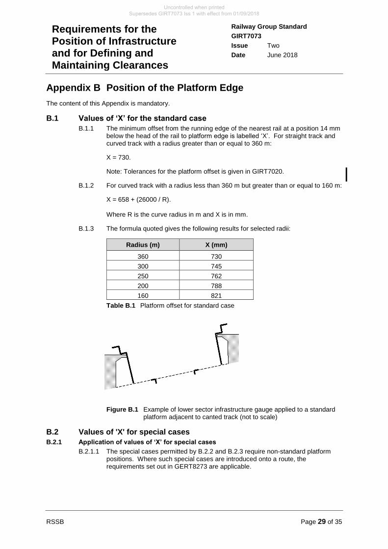
Figure B.1 Example of lower sector infrastructure gauge applied to a standard platform adjacent to canted track (not to scale)
B.2 Values of 'X' for special cases
B.2.1 Application of values of ‘X’ for special cases
B.2.1.1 The special cases permitted by B.2.2 and B.2.3 require non-standard platform positions. Where such special cases are introduced onto a route, the requirements set out in GERT8273 are applicable.
Uncontrolled when printed Supersedes GIRT7073 Iss 1 with effect from 01/09/2018
Page 30 of 35 RSSB
Railway Group Standard
GIRT7073
Issue Two
Date June 2018
Requirements for the Position of Infrastructure and for Defining and Maintaining Clearances
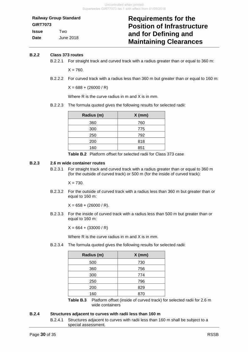
B.2.2 Class 373 routes
B.2.2.1 For straight track and curved track with a radius greater than or equal to 360 m:
X = 760.
B.2.2.2 For curved track with a radius less than 360 m but greater than or equal to 160 m:
X = 688 + (26000 / R)
Where R is the curve radius in m and X is in mm.
B.2.2.3 The formula quoted gives the following results for selected radii:
Radius (m) X (mm)
360 760
300 775
250 792
200 818
160 851
Table B.2 Platform offset for selected radii for Class 373 case
B.2.3 2.6 m wide container routes
B.2.3.1 For straight track and curved track with a radius greater than or equal to 360 m (for the outside of curved track) or 500 m (for the inside of curved track):
X = 730.
B.2.3.2 For the outside of curved track with a radius less than 360 m but greater than or equal to 160 m:
X = 658 + (26000 / R).
B.2.3.3 For the inside of curved track with a radius less than 500 m but greater than or equal to 160 m:
X = 664 + (33000 / R)
Where R is the curve radius in m and X is in mm.
B.2.3.4 The formula quoted gives the following results for selected radii:
Radius (m) X (mm)
500 730
360 756
300 774
250 796
200 829
160 870
Table B.3 Platform offset (inside of curved track) for selected radii for 2.6 m wide containers
B.2.4 Structures adjacent to curves with radii less than 160 m
B.2.4.1 Structures adjacent to curves with radii less than 160 m shall be subject to a special assessment.
Uncontrolled when printed Supersedes GIRT7073 Iss 1 with effect from 01/09/2018
RSSB Page 31 of 35
Railway Group Standard
GIRT7073
Issue Two
Date June 2018
Requirements for the Position of Infrastructure and for Defining and Maintaining Clearances
Definitions
Absolute gauging
Absolute gauging of a vehicle is a full assessment of clearances on a section of track between the vehicle and fixed infrastructure, and between the vehicle and vehicles on adjacent tracks.
Altered infrastructure
For the purpose of this document, the substantial rebuilding of all or part of an existing structure or infrastructure, which provides a reasonable opportunity to achieve normal clearances in the upper sector or, for the lower sector, meet the requirements of Lower Sector Infrastructure Gauge.
Clearance
The minimum calculated distance between the swept envelope of a vehicle and fixed infrastructure, or between swept envelopes of two vehicles on adjacent tracks.
Comparative gauging
The process of comparing the swept envelopes of a vehicle new to a route, with the swept envelopes of a vehicle or vehicles which have been demonstrated to be able to use the proposed route.
Effective position of the track
A position that the track could credibly occupy in relation to structures or an adjacent track at some point within its maintenance cycle, giving the smallest clearances. Compare with ‘Maintained position of the track’.
Exceptional load
A vehicle or vehicle load that is subject to special operating arrangements, which are determined before authority to travel is granted.
Exposed location
A location on a route which is orientated generally in a north-south direction and which features hillsides, embankments or viaducts which are open and exposed to south-westerly winds. Examples of such routes are: West Coast Main Line north of Weaver Junction, and locations on the Cumbrian Coast Line.
Gauge
Used to refer to a vehicle gauge or structure gauge where the context makes it clear which is meant. See ‘Vehicle gauge’.
Gauging
The process by which swept envelopes of a vehicle or a standard vehicle gauge are used to determine clearances on a section of track between the vehicle and fixed infrastructure and between the vehicle and vehicles on adjacent tracks.
Infrastructure
Compare with ‘Structure’. For the purpose of this document, the principal elements are track and structures in combination, but also include railway equipment and support systems (for example, cables and cable supports and signs).
Load
For the purposes of this document, a load is defined as the physical size of the payload carried by a wagon.
Uncontrolled when printed Supersedes GIRT7073 Iss 1 with effect from 01/09/2018
Page 32 of 35 RSSB
Railway Group Standard
GIRT7073
Issue Two
Date June 2018
Requirements for the Position of Infrastructure and for Defining and Maintaining Clearances
Lower sector
The area up to and including 1100 mm above the plane of the rails. See also ‘Upper sector’.
Maintained position of the track
The position in which the track should be placed during maintenance. Compare with ‘Effective position of the track’.
New infrastructure
Infrastructure other than that which already exists. The term excludes disused infrastructure that is brought back into use without alteration.
New railway line
For the purpose of this document a ‘new line’ means a line that creates a route where none currently exists (as set out in the Infrastructure TSI 2014).
Normal clearance
A clearance between a structure and a vehicle or between passing vehicles on adjacent tracks which does not require specific controls on the position of the track, but which does require the relative locations of structures and adjacent tracks to be monitored and maintained.
Out-of-gauge load
An exceptional load, by virtue of its size.
Overthrow
A geometric projection of a vehicle when on curved track.
Passing clearance
The minimum calculated distance between the swept envelopes of two specific types of rail vehicle as they pass on adjacent tracks at nominated speeds, taking account of appropriate track tolerances and accuracy of measurement.
Permissible or enhanced permissible speed
The maximum speed published in the Sectional Appendix at which traffic is allowed to run on a line.
Plane of the rails
An imaginary surface coplanar with the top of both rails of a track.
Reduced clearance
A clearance, less than a normal clearance, which requires special measures to maintain tracks relative to adjacent tracks and structures.
Route
The physical path of a journey to be undertaken by a vehicle or a collection of vehicles, where the path is comprised of a number of track sections, each of which has individually defined characteristics.
Section of track
Track bounded by identified limits such as junctions, terminals or points at which there is a significant change in traffic flow or permissible speed.
Uncontrolled when printed Supersedes GIRT7073 Iss 1 with effect from 01/09/2018
RSSB Page 33 of 35
Railway Group Standard
GIRT7073
Issue Two
Date June 2018
Requirements for the Position of Infrastructure and for Defining and Maintaining Clearances
Special reduced clearance
A clearance, less than a reduced clearance, which requires a specific risk assessment to be undertaken and the implementation of appropriate controls to demonstrate that risks have been reduced to as low as reasonably practicable (ALARP).
Standard vehicle gauge
An outline drawing or specification of a notional vehicle, which prescribes maximum permissible vehicle and loading dimensions, certain suspension displacements, and certain curve overthrow limitations, for example, W6a gauge.
Structure
Compare with ‘Infrastructure’. An element of the infrastructure adjacent to, or crossing over, a railway track. So far as this document is concerned ‘structures’ include, but are not limited to:
a) Train control and communications equipment, for example, signals.
b) Station platforms.
c) Overhead line equipment supporting structures at earth potential, but excluding insulators.
d) Civil engineering structures such as retaining walls, tunnels and bridges.
e) Other isolated structures.
f) Temporary works.
Structure clearance
The minimum calculated distance between a structure and the swept envelope of a specific type of rail vehicle passing at nominated speeds, taking account of appropriate track tolerances and accuracy of measurement.
Swept envelope
A cross-sectional profile, taken at right angles to the track, enclosing all dynamic movements, static deflections and overthrows of all points along the surface of the vehicle that can reasonably be expected to occur under the appropriate range of operating conditions as it sweeps past a theoretical track location. A family of swept envelopes is required to define a vehicle’s behaviour on a route.
The swept envelopes referred to within this document exclude the effects of track tolerance and rail sidewear previously included in kinematic envelopes developed under GMRT2149 issue one or earlier documents.
Ten minute mean wind speed
Speed of the instantaneous wind averaged over 10 minutes, as defined in BS EN 1991-1-4 2005, Eurocode 1, wind actions.
Track fixity
The degree to which a track is restrained from movement in any direction. Track fixity can be different laterally and vertically, and can be asymmetric.
Track interval
The distance between the running edges of the nearest rails of adjacent tracks measured 14 mm below the plane of the rails.
Uncontrolled when printed Supersedes GIRT7073 Iss 1 with effect from 01/09/2018
Page 34 of 35 RSSB
Railway Group Standard
GIRT7073
Issue Two
Date June 2018
Requirements for the Position of Infrastructure and for Defining and Maintaining Clearances
Upper sector
The area above 1100 mm above the plane of the rails. See also ‘Lower sector’.
Vehicle gauge
The maximum envelope that a vehicle conforming to the gauge is permitted to occupy statically and dynamically, which prescribes maximum permissible vehicle and loading dimensions, certain suspension displacements, and certain curve overthrow limitations, for example, W6a gauge.
Uncontrolled when printed Supersedes GIRT7073 Iss 1 with effect from 01/09/2018
RSSB Page 35 of 35
Railway Group Standard
GIRT7073
Issue Two
Date June 2018
Requirements for the Position of Infrastructure and for Defining and Maintaining Clearances
References
The Catalogue of Railway Group Standards gives the current issue number and status of documents published by RSSB. This information is also available from https://www.rssb.co.uk/railway-group-standards.
RGSC 01 Railway Group Standards Code
RGSC 02 Standards Manual
Documents referenced in the text
Railway Group Standards
GERT8025 Electrical Protective Provisions for Electrified Lines
GERT8073 Requirements for the Application of Standard Vehicle Gauges
GERT8273 Assessment of Compatibility of Rolling Stock and Infrastructure − Gauging and Stepping Distances
GIRT7020 GB Requirements for Platform Height, Platform Offset and Platform Width
GLRT1210 AC Energy Subsystem and Interfaces to Rolling Stock Subsystem
GMRT2149 Requirements for Defining and Maintaining the Size of Railway Vehicles (withdrawn)
GMRT2173 Requirements for the Size of Vehicles and Position of Equipment
RSSB documents
GEGN8573 Guidance on Gauging and Platform Distances
RIS-2773-RST Format for Vehicle Gauging Data
RIS-7016-INS Interface between Station Platforms, Track, Trains and Buffer Stops
RIS-8270-RST Route Level Assessment of Technical Compatibility between Vehicles and Infrastructure
Uncontrolled when printed Supersedes GIRT7073 Iss 1 with effect from 01/09/2018