Embed Size (px)
Citation preview
Requirements for the integrating system (Demo 1)
Deliverable nº: 2.4
.
EC-GA nº Project full title:
295977 Demonstration of two floating wind
turbine systems for power generation
in Mediterranean deep waters
Deliverable Nº 2.2
Requirements for the integrating system (Demo 1)
Responsible Partner: GAMESA
Due Date of Deliverable: 31/03/2013
WP: 2
WP leader: GAMESA
Task: 2.4 Requirements for the integrating system
Task leader: GAMESA
Version: 1
Version date: 2/03/13
Written by: GAMESA
Checked by: GAMESA
Approved by: GAMESA
Dissemination level: PU
Document history
Version Date Main Modification Written by Checked by Approved by
1 2/03/13 - GAMESA GAMESA GAMESA
Brief Summary
Floatgen demonstrator nº 1 will be a 2MW demonstrator that will use a 2MW GAMESA wind turbine
mounted on an IDEOL ring-shaped surface floating platform. The aim of this requirement definitions
is to set out the basic specifications that will apply to the Transition Piece that serve as joint between
floater and wind turbine.
The interface between tower and substructure will be site specific. A transition piece is needed
between the substructure and the WTG Tower.

TABLE OF CONTENTS
1. Executive Summary ...................................................................................................................................... 3
2. Acronyms ..................................................................................................................................................... 4
3. ENVIRONMENTAL DESIGN CONDITIONS ....................................................................................................... 5
4. DESIGN PHILOSOPHY .................................................................................................................................... 5
4.1 GENERAL ....................................................................................................................................................... 5
4.2 FUNCTIONNAL REQUIREMENTS ................................................................................................................... 5
4.3 INTERFACE MANAGEMENT .......................................................................................................................... 5 4.3.1 MECHANICAL CONNECTION BETWEEN THE TP AND THE TOWER ......................................................................... 5 4.3.2 . EQUIPMENT ......................................................................................................................................................... 6
4.4 STRUCTURAL DESIGN AND STRUCTURAL INTEGRITY ................................................................................... 6
4.5 DESIGN LIFE .................................................................................................................................................. 6
4.6 MANAGEMENT OF ACCIDENTAL CASES........................................................................................................ 6
4.7 MAINTENANCE ............................................................................................................................................. 7 4.7.1 GENERAL ................................................................................................................................................................ 7 4.7.2 INSPECTION PLAN .................................................................................................................................................. 7 4.7.3 REPAIR AND CHANGE ............................................................................................................................................. 7 4.7.4 TRANSIENT CONDITIONS ........................................................................................................................................ 7
5. EQUIPMENT ................................................................................................................................................. 7
5.1 GENERAL ....................................................................................................................................................... 7
5.2 PERSONNEL ACCESS...................................................................................................................................... 7 5.2.1 ACCESS INSIDE TP ................................................................................................................................................... 7 5.2.2 ACCESS OUTSIDE THE TP ........................................................................................................................................ 7
5.3 CABLES, PIPING AND CONNECTIONS TO BE INTEGRATED ............................................................................ 8 5.3.1 INSIDE THE TP ........................................................................................................................................................ 8 5.3.2 PENETRATIONS THROUGH THE TP ......................................................................................................................... 8 5.3.3 OUTSIDE THE TP ..................................................................................................................................................... 8
6. MATERIAL..................................................................................................................................................... 9
7. STRUCTURAL STRENGTH VERIFICATION ....................................................................................................... 9
7.1 STATIC ANALYSIS .......................................................................................................................................... 9 7.1.1 GENERAL METHOD ................................................................................................................................................. 9 7.1.2 INPUT DATA ........................................................................................................................................................... 9 7.1.3 CHECKLIST AND CALCULATION METHOD ............................................................................................................. 10 7.1.4 FEA MODEL .......................................................................................................................................................... 11 7.1.5 INTERFACE WITH GAMESA TO ACCOUNT FOR SUPPORT STRUCTURE FLEXIBILITY .............................................. 11
7.2 FATIGUE ASSESSMENT................................................................................................................................ 12 7.2.1 GENERAL METHOD ............................................................................................................................................... 12 7.2.2 INPUT DATA ......................................................................................................................................................... 12 7.2.3 CHECKLIST AND CALCULATION METHOD ............................................................................................................. 13 7.2.4 FEA MODEL .......................................................................................................................................................... 13 7.2.5 INTERFACE WITH GAMESA FOR RESULTS CHECK ................................................................................................. 13
8. MANUFACTURING AND INSPECTION .......................................................................................................... 13
8.1 GENERAL ..................................................................................................................................................... 13
8.2 PRE-FABRICATION VERIFICATIONS ............................................................................................................. 13
8.3 WELDING & NDT ......................................................................................................................................... 14
8.4 INTERFACE WITH THE TOWER .................................................................................................................... 14
8.5 TAGGING, MARKING AND PAINTING .......................................................................................................... 14
Requirements for the integrating system (Demo 1)
06/02/13 2
8.5.1 PAINTING OUTSIDE TP ......................................................................................................................................... 14 8.5.2 TAGGING AND MARKING ON THE TP ................................................................................................................... 14
8.6 MACHINING ................................................................................................................................................ 14
8.7 CORROSION PROTECTION .......................................................................................................................... 14
8.8 QUALITY ASSURANCE ................................................................................................................................. 15
8.9 CERTIFICATION / CLASSIFICATION .............................................................................................................. 15 8.9.1 GENERAL .............................................................................................................................................................. 15 8.9.2 MATERIAL CERTIFICATION AND TRACEABILITY .................................................................................................... 15
9. CONTROL / TESTING ................................................................................................................................... 15
9.1 SAFETY ........................................................................................................................................................ 15
9.2 CONTROL AND TESTING BEFORE PAINTING ............................................................................................... 15
9.3 CONTROL/TESTING AFTER ASSEMBLY ........................................................................................................ 15
10. PRESERVATION, PACKING AND SHIPPING................................................................................................. 16
10.1 PREPARATION FOR SEAFASTENING/ TRANSPORT .................................................................................... 16
10.2 PACKING ................................................................................................................................................... 16
11. LIFTING ..................................................................................................................................................... 16
12. INSTALLATION AND ASSEMBLING ............................................................................................................ 16
12.1 UNPACKING, INSPECTION AND INSTALLATION ........................................................................................ 16
12.2 ASSEMBLY ................................................................................................................................................. 16
13. System KPI’s ............................................................................................................................................. 16
13.1 WEATHER STANDBY DURING INSTALLATION ........................................................................................... 17
13.2 OPERATIONAL WEATHER STANDBY ......................................................................................................... 17
13.3 PRICE VOLATILITY ..................................................................................................................................... 17
13.4 CO2 CONTENT .......................................................................................................................................... 17
APPENDIX 1: Floatgen interface definitions.................................................................................................... 18
Requirements for the integrating system (Demo 1)
06/02/13 3
1. EXECUTIVE SUMMARY
The main objective of the Floatgen is to demonstrate the technical and economic feasibility of two
different multi-megawatt integrated floating-wind turbine systems in deep waters, in order to extend
deep offshore wind resources and demonstrate a decrease of costs for electricity generation down to
competitive level.
The objective of task 2.4 is to establish which are the main aspects related to the interface between
the wind turbine and the floating platform.
The scope of this document is to list the basic requirements are necessary for the interface between
the wind turbine and the floating platform from the point of view of both types of infrastructures.
This document outlines the environmental design conditions, provides the basic input data and
design philosophy to be used while developing the concept and outlines the main requirements
regarding the equipment, materials, structural strength verification, etc.
Other documents pertaining to the wind turbine, floating system and regulatory framework collects
the data necessary for the design of these specific tasks.

Requirements for the integrating system (Demo 1)
06/02/13 4
2. ACRONYMS
FAT Factory Acceptance Tests
LRFD Load and Resistance Factor Design
NDE Non Destructive Examination
NDT Non Destructive Test
SMYS Specified Minimum Yield Strength
SUBCONTRACTOR Means the Supplier, Manufacturer or Vendor of the goods and/or services.
TP Transition Piece
GL Germanischer Lloyd
DNV Det Norske Veritas
The following sketch defines the different parts referenced in the present specification:
FIGURE 1 DEFINITION OF THE FLANGES
Requirements for the integrating system (Demo 1)
06/02/13 5
3. ENVIRONMENTAL DESIGN CONDITIONS
The environmental conditions are described in document RD WT. The TP is located both in the splash
zone and above it (dry external surfaces). The TP may be subjected to all the kind of wave loads (i.e.
wave impact loads, slamming and green water) which shall be considered in the design. The design
parameters are the following ones:
- Max. design temperature: +40 °C
- Min. design temperature: -30°C
4. DESIGN PHILOSOPHY
4.1 GENERAL
The general requirements applied to the floater are described in Platform design requirements.
The main objective of the design of a Transition Piece is to ease the interface between floater and
wind turbine.
4.2 FUNCTIONNAL REQUIREMENTS
The primary function of the TP is the structural connection between the floater and the tower. The
minimum interface location and external platform level sections (meters above sea) depends of the
final prototype site. A procedure has been agreed and will be applied in the relevant project RDs:
G12-13-ECM001 Tower to floater interface.
The TP is composed of bolted flanges and is assembled to the floater concrete structure by means of
pre stressed bars. The equipment is described in Section 5. The mechanical connection between the
TP and the tower shall ensure water tightness against waves, rainfalls and storms in order to protect
the electrical equipment located inside the tower.
4.3 INTERFACE MANAGEMENT
4.3.1 MECHANICAL CONNECTION BETWEEN THE TP AND THE TOWER
The design of the TP is part of IDEOL scope except for the mechanical connection with the tower.
This mechanical connection is the scope of GAMESA.
The TP top flange will be welded to the TP and shall be provided by GAMESA to IDEOL. It includes the
following data:
- The dimensional characteristics, the dimensional tolerances, the geometric tolerances and the
surface roughness of the contact surface between the TP top flange and the Tower bottom flange
- The material of the TP bottom flange
Requirements for the integrating system (Demo 1)
06/02/13 6
- A drawing of the mechanical connection, which includes the dimensions and their tolerances
related to the assembly.
- The procedures for the following operations:
∙ inspection
∙ corrosion protection
∙ preservation, packing and shipping
∙ lifting
∙ Testing (1) on the assembly: water tightness, bolt tension,
- The bolting features
- Contact compound (or other technological solution) for water tightness (2), if necessary.
Note:
(1): Testing at the construction site is the scope of IDEOL
(2): A contact compound could also be used for corrosion protection or/and conductivity purposes.
4.3.2 . EQUIPMENT
The specifications of the equipment coming from the tower shall be provided by GAMESA to IDEOL.
It includes the following data for each device:
- The dimensional characteristics.
- The weight.
- The location (dimensional characteristics) inside the TP, when necessary.
- The technological solutions for the assembling means, when necessary.
and the coordinates of the Center of Gravity of the whole equipment.
4.4 STRUCTURAL DESIGN AND STRUCTURAL INTEGRITY
The connections of secondary structure on primary structural members are designed for minimum
impact on the structural integrity of the TP, because of failure risk. Welded supports are used for
equipment integration. The structural integrity check is described in Section 7.
4.5 DESIGN LIFE
The design life will be 20 years.
4.6 MANAGEMENT OF ACCIDENTAL CASES
As per Platform design requirements document.
Requirements for the integrating system (Demo 1)
06/02/13 7
4.7 MAINTENANCE
4.7.1 GENERAL
As per Platform design requirements.
4.7.2 INSPECTION PLAN
The inspection plan shall include following checks:
- All welded lines.
- Bolting for the TP bottom flange: Access to inner and outer bolting for the bottom TP flange is
therefore required for visual inspection, re-tensioning or dismounting/ mounting purposes. A
bolt tensioner has a weight of about 50 – 100 kg, and a hydraulic pump of about 30 – 100 kg.
- Water tightness (hose test) for the TP bottom and top flanges.
- Search for corrosion spots.
4.7.3 REPAIR AND CHANGE
The TP is repairable by means of welding.
4.7.4 TRANSIENT CONDITIONS
As per Platform design requirements.
5. EQUIPMENT
5.1 GENERAL
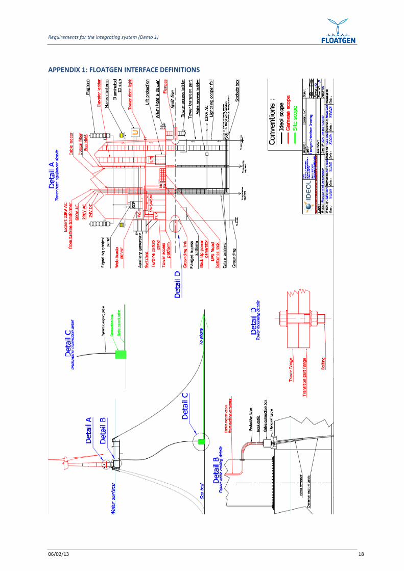
The equipment is outlined in the drawing presented in the Appendix 1.
The access equipment is described in the IDEOL drawings and specifications.
As specified in section 4.4, the only technological solution for the equipment integration on the TP
wall is welded supports.
5.2 PERSONNEL ACCESS
5.2.1 ACCESS INSIDE TP
The TP inside is composed of the following devices:
- Main access ladder / stairs.
- Access platform (for the inspection of TP top flange).
5.2.2 ACCESS OUTSIDE THE TP
The equipment which is outside the TP is the following one:
- a tower access ladder/stairs
Requirements for the integrating system (Demo 1)
06/02/13 8
- Scaffolding/ staging for work at height
The structural connections between the tower and the equipment above are designed in order to
avoid any structural failure of the tower, as specified in Section 4.4. Welded supports should
therefore be used.
5.3 CABLES, PIPING AND CONNECTIONS TO BE INTEGRATED
5.3.1 INSIDE THE TP
Following cables, piping or connections will be integrated inside the TP:
- The static export cable:
∙ Power cables to / from shore
∙ Signal cables to / from shore
- Cable for grounding
- Grounding link between the TP and the tower
- Sounding pipes (if sounding pipes from compartment underneath are located inside the TP)
- Lightning copper foil
- Cable connection,
- Connection boxes
The cables and the piping are installed according to IDEOL diagrams.
5.3.2 PENETRATIONS THROUGH THE TP
Following components (*) will be integrated at the inside/outside interface of the TP:
- Bulkhead crossing for the sockets boxes (for temporary electrical power supply, like for marine
safety equipment or for maintenance tools.
- Bulkhead crossing for the deck static export cable
NOTE:
(*) stuffing boxes for pipe penetrations through structure
5.3.3 OUTSIDE THE TP
No cables, piping or connections will be integrated outside the tower

Requirements for the integrating system (Demo 1)
06/02/13 9
6. MATERIAL
The material is chosen according to class rules.
The material shall be easily weldable.
7. STRUCTURAL STRENGTH VERIFICATION
7.1 STATIC ANALYSIS
7.1.1 GENERAL METHOD
The static analysis is performed in the following chronological order of actions:
- IDEOL: calculation of the dimensions of the floater
- GAMESA: calculation of the max loads at the bottom of the tower.
- IDEOL: FEA analysis of the TP (FEA model of floater deck + TP +Bottom of tower) to assess stress
distribution in tower / flange connecting bolts.
- GAMESA checks the results from IDEOL calculations.
- GAMESA completes tower design including floater / TP flexibility.
- IDEOL completes the design of the TP including influence of tower.
The static analysis is performed according to class rules.
7.1.2 INPUT DATA
The static analysis requires the following input data:
- from GAMESA:
∙ Dimension of the tower (thickness, height, diameter)
∙ All loads: all moments (bending and torque moments) and all forces (axial and shear forces).
∙ Tower bottom flange drawing and material characteristics.
- from IDEOL:
∙ Floater physical data:
• Floater coordinates axis description.
• Floater main dimensions.
• Distance from tower bottom to floater bottom.
• Floater CoG respect to floater axis.
• Mass and moments of inertia.
• Radius of gyration respect to CoG of the floater.
Requirements for the integrating system (Demo 1)
06/02/13 10
• Metacentre position.
• Submerged volume (equilibrium).
• Buoyancy centre.
• Equivalent diameter of the floater at MSL.
∙ Mooring system:
• Number of mooring lines.
• Coordinates of connection points with the floater.
• Coordinates of end points with the seabed.
• Un-stretched mooring lines length.
• Equivalent mooring line weight per unit length in water.
• Equivalent mooring line extensional stiffness.
• Coefficient of the static-friction drag between the seabed and a mooring line.
∙ Hydrodynamic behaviour.
• Time series of displacements, speeds and accelerations for the 6 dof of the platform in
order to adjust the aero elastic model (additional linear damping, additional yaw spring
stiffness and so on). Simple load cases shall be considered.
• Maximum expected displacements of floater dof.
• Added mass (aij) in frequency domain for radiation problem.
• Damping coefficients (bij) in frequency domain for radiation problem.
• Hydrodynamic drag coefficient.
• Hydrodynamic inertia coefficient.
These input data will be addressed by interface sheets.
7.1.3 CHECKLIST AND CALCULATION METHOD
List of the components and/or areas to be checked and related calculation methods:
- Structural strength of the TP:
∙ FEA calculation (mainly including the load case related to the max bending moment)
∙ Modal analysis by means of FEA
∙ Buckling analysis by means of FEA combined with analytical buckling limit state verification.
- Strength check of the bottom bolting:

Requirements for the integrating system (Demo 1)
06/02/13 11
∙ FEA calculation
- Strength check of the top bolting: this calculation is the scope of GAMESA
NOTE:
In the calculations performed by IDEOL, the bolting of the TP top flange is not included in the FEA
model of the tower. The TP top flange and the Tower bottom flange are considered glued.
7.1.4 FEA MODEL
The FEA model including the TP for its structural strength check is described as follows:
- Material behavior of the TP: elastic calculation
- Boundary of the geometry:
∙ At the top of the TP: it includes geometrical discontinuities (like openings) when relevant.
∙ At the bottom of the TP: the slab where the TP is bolted and the hull (partially represented
in Appendix 1) are modeled so that their stiffness is taking into account.
- Assumptions: Equipment will be modeled by means of lump mass.
- Boundary conditions.
- Meshing, elements for the TP: 2D elements. Local modeling is performed by means of 3D
elements.
- Criteria for the structural strength verification: the maximum allowed Von Misses stress is the
value “SMYS / material factor” if the LRFD method is used.
7.1.5 INTERFACE WITH GAMESA TO ACCOUNT FOR SUPPORT STRUCTURE FLEXIBILITY
As presented in section 7.1.1, GAMESA will check the structural integrity of the tower. For this
purpose, IDEOL will provide the following results:
- The curve “displacement=f (θ)” (using polar coordinates) in the location of the weld line of the
TP top flange.
- Some plots of the stress distribution around the door (which is out of the TP)
- IDEOL can alternatively provide to GAMESA the following input data that can be included in the
GAMESA models:
- Stiffness matrix at the TP/hull interface and the TP properties
∙ The hull and the TP properties (geometry, material) and their boundary conditions so that
these components can be modeled by FEA.
Requirements for the integrating system (Demo 1)
06/02/13 12
7.2 FATIGUE ASSESSMENT
7.2.1 GENERAL METHOD
As a first calculation approach, the fatigue assessment method is conservatively based on the
assumptions that:
- The peaks of bending moment, torsion moment, shear force and axial force are simultaneous.
- The Hot Spots for each load are considered always located at the same point.
- Each bending stress range Δσ bending i (1) occurring for ni cycles number is combined with the
following stress ranges, by means of the Von Misses stress calculation:
∙ the max stress range (2) of the torsion moment
∙ the max stress range (2) of shear force
∙ the max stress range (2) of axial force
As these assumptions are largely conservative, the method could be fine-tuned if first calculations
give too high fatigue damage results.
Additionally, the Stress Concentration Factor for each Hot Spot is considered as the ones from the
FEA model using static loading, presented in Section 7.1 and relevant S-N curve according to
structural detail classification.
NOTE:
(1): The bending stress range (noted Δσ bending i , for this document) is calculated from the bending
moment range (noted ΔMbi, for this document) which comes from the Long Term Distribution of
bending moment.
(2): The max stress range among all the simulations time is considered.
7.2.2 INPUT DATA
The fatigue analysis requires the following input data:
- from GAMESA:
∙ Long Term Distribution of bending moment
∙ The max stress range of the torsion moment
∙ The max stress range of the shear force
∙ The max stress range of the axial force
These loads are calculated at the location of the TP bottom flange, and for the 20 year return Period.
- from Ideol:
∙ (See 7.1.2)
Requirements for the integrating system (Demo 1)
06/02/13 13
These input data will be addressed by interface sheets.
7.2.3 CHECKLIST AND CALCULATION METHOD
List of the components/ areas to be checked:
- TP cylinder wall
- All weld lines
- Bottom bolting
- Top bolting: this calculation is the scope of GAMESA
7.2.4 FEA MODEL
The SCF are calculated by means of the FEA model used for the static analysis presented before and
the S-N curve is selected to account for the structural detail classification.
7.2.5 INTERFACE WITH GAMESA FOR RESULTS CHECK
No check of the fatigue assessment has been planned by GAMESA.
8. MANUFACTURING AND INSPECTION
8.1 GENERAL
The TP is composed of a cylindrical cylinder whose each end is welded to a flange. These TP flanges
comprise holes for bolted assembling. The bolted connection between the TP top flange and the
Tower bottom flange requires water tightness so as to prevent water ingress. The design of the TP
top flange is typical steel bolted flange connection whereas the design of the TP bottom flange is
more specific to concrete foundation design.
8.2 PRE-FABRICATION VERIFICATIONS
All raw material (plates, flanges) and bolting components shall be inspected to be in accordance with
order drawings and specification requirements (*). If the components show damages or if
discrepancies exist between the relevant IDEOL drawings and the as-built dimensions, the
SUBCONTRACTOR shall immediately advise IDEOL.
NOTE:
Requirements for the integrating system (Demo 1)
06/02/13 14
(*) This requirement regarding the raw material shall be fulfilled before further fabrication steps can
be engaged.
8.3 WELDING & NDT
Welding and NDT shall be carried out in accordance with class rules.
8.4 INTERFACE WITH THE TOWER
As per Section 4.3.
8.5 TAGGING, MARKING AND PAINTING
8.5.1 PAINTING OUTSIDE TP
All the outside wall of the TP shall be painted in yellow from a color code as per local marine
navigation rules. This yellow paint shall be also class approved for corrosion purpose.
8.5.2 TAGGING AND MARKING ON THE TP
A marking for installation purpose is carried out in order to distinguish the TP top flange from the TP
bottom flange, and to locate the angular position.
8.6 MACHINING
The TP flanges (including the holes for the bolted connections) and the TP ends (before the flanges
are welded) are machined.
Machining shall be in accordance with IDEOL drawings.
The SUBCONTRACTOR shall perform all necessary dimensional controls and prepare a Metrological
report showing as built values versus required dimensions.
The SUBCONTRACTOR shall submit the template for the Metrological report to IDEOL for review and
approval.
Any non-conformance must be recorded, documented and approval shall be obtained from IDEOL
prior to any corrective action.
8.7 CORROSION PROTECTION
The corrosion protection is carried out by means of painting and cathodic protection (using anodes).
Requirements for the integrating system (Demo 1)
06/02/13 15
8.8 QUALITY ASSURANCE
The SUBCONTRACTOR shall fully implement a Quality management system in accordance with class
rules and including all relevant requirements of their associated guidance document in accordance
with class rules.
The SUBCONTRACTOR shall develop and implement a Quality plan, which shall be subject to approval
by IDEOL.
8.9 CERTIFICATION / CLASSIFICATION
8.9.1 GENERAL
The Classification Society for the TP shall be GL, DNV or similar.
8.9.2 MATERIAL CERTIFICATION AND TRACEABILITY
Required material certifications and traceability levels of components shall be described.
9. CONTROL / TESTING
9.1 SAFETY
Before any Functional Acceptance Tests, following requirements must be fulfilled:
- A team leader for the operations has been designated by the SUBCONTRACTOR.
- The roles, the responsibilities shall be clearly defined prior the tests,
- All involved personnel shall be equipped with the equipment appropriated to the safety and
their tasks
- The FAT area shall be indicated (eg. by means of red tape) and only authorized personnel
designated by the team leader will access this area,
9.2 CONTROL AND TESTING BEFORE PAINTING
The tests listed below shall be performed after the completion of manufacturing, except for painting:
- The mounting on the TP top flanges: it is checked by means of a dimensional control according
to GAMESA drawings.
- The mounting on the welded supports for equipment: it is checked by means of a dimensional
control of their locations, according to IDEOL drawings.
9.3 CONTROL/TESTING AFTER ASSEMBLY
The tests listed below shall be performed after painting:
- Electrical continuity for corrosion protection purpose
Requirements for the integrating system (Demo 1)
06/02/13 16
- Water tightness of the bolted flange connection between the TP top flange and the Tower
bottom flange.
10. PRESERVATION, PACKING AND SHIPPING
10.1 PREPARATION FOR SEAFASTENING/ TRANSPORT
The TP shall be transported vertically using suitable wooden blocks.
The transport arrangement design shall include secure fastening to ensure safe handling (no rolling
on the TP flanges).
It shall be verified that the TP will experience no permanent deformations during the transport.
10.2 PACKING
All packing shall be clearly marked for shipping, including lifting points, weight, dimensions, list of
contents.
11. LIFTING
The lifting will be carried out by means of [HOLD].
The TP design will include lifting points (trunions or pad eyes), which will be dimensioned in
accordance with class rules.
12. INSTALLATION AND ASSEMBLING
12.1 UNPACKING, INSPECTION AND INSTALLATION
All contact surfaces of the TP flanges shall be thoroughly cleaned and inspected prior to assembly
operations.
Only the boxes of seals (for the stuffing boxes, and eventually for the TP flanges) which are directly
needed shall be opened.
12.2 ASSEMBLY
Assembly of the TP on the floater will be done afloat.
Assembly of the Wind turbine on the TP will be afloat.
13. SYSTEM KPI’S
Specific installed + commissioned floating wind turbine cost
Defined as Substructure cost + turbine assembly + commissioning and Installed power.
Requirements for the integrating system (Demo 1)
06/02/13 17
13.1 WEATHER STANDBY DURING INSTALLATION
Defined as % of standby due to weather for all operations during offshore installation.
13.2 OPERATIONAL WEATHER STANDBY
Defined as % of standby due to weather (wind, waves, other) or % of annual operability.
13.3 PRICE VOLATILITY
Economic model to be built and indexed on main parameters (fuel cost, steel cost, cement cost,
vessels chartering rates, etc…)
13.4 CO2 CONTENT
Defined as amount of CO2 emitted / installed MW
Requirements for the integrating system (Demo 1)
06/02/13 18
APPENDIX 1: FLOATGEN INTERFACE DEFINITIONS